EP3128115A1 - Roller tube electrical motor and roller shade positioning control system - Google Patents
Roller tube electrical motor and roller shade positioning control system Download PDFInfo
- Publication number
- EP3128115A1 EP3128115A1 EP15822899.9A EP15822899A EP3128115A1 EP 3128115 A1 EP3128115 A1 EP 3128115A1 EP 15822899 A EP15822899 A EP 15822899A EP 3128115 A1 EP3128115 A1 EP 3128115A1
- Authority
- EP
- European Patent Office
- Prior art keywords
- motor
- reel pipe
- power supply
- cone pulley
- switch
- Prior art date
- Legal status (The legal status is an assumption and is not a legal conclusion. Google has not performed a legal analysis and makes no representation as to the accuracy of the status listed.)
- Granted
Links
- 239000011324 bead Substances 0.000 claims abstract description 39
- 238000005096 rolling process Methods 0.000 claims abstract description 23
- 230000009467 reduction Effects 0.000 claims abstract description 20
- 239000004744 fabric Substances 0.000 claims description 21
- 238000012986 modification Methods 0.000 description 2
- 230000004048 modification Effects 0.000 description 2
- 238000004804 winding Methods 0.000 description 2
- 230000009471 action Effects 0.000 description 1
- 230000004913 activation Effects 0.000 description 1
- 230000007547 defect Effects 0.000 description 1
- 230000006698 induction Effects 0.000 description 1
Images


Classifications
-
- E—FIXED CONSTRUCTIONS
- E06—DOORS, WINDOWS, SHUTTERS, OR ROLLER BLINDS IN GENERAL; LADDERS
- E06B—FIXED OR MOVABLE CLOSURES FOR OPENINGS IN BUILDINGS, VEHICLES, FENCES OR LIKE ENCLOSURES IN GENERAL, e.g. DOORS, WINDOWS, BLINDS, GATES
- E06B9/00—Screening or protective devices for wall or similar openings, with or without operating or securing mechanisms; Closures of similar construction
- E06B9/56—Operating, guiding or securing devices or arrangements for roll-type closures; Spring drums; Tape drums; Counterweighting arrangements therefor
- E06B9/68—Operating devices or mechanisms, e.g. with electric drive
- E06B9/72—Operating devices or mechanisms, e.g. with electric drive comprising an electric motor positioned inside the roller
-
- E—FIXED CONSTRUCTIONS
- E06—DOORS, WINDOWS, SHUTTERS, OR ROLLER BLINDS IN GENERAL; LADDERS
- E06B—FIXED OR MOVABLE CLOSURES FOR OPENINGS IN BUILDINGS, VEHICLES, FENCES OR LIKE ENCLOSURES IN GENERAL, e.g. DOORS, WINDOWS, BLINDS, GATES
- E06B9/00—Screening or protective devices for wall or similar openings, with or without operating or securing mechanisms; Closures of similar construction
- E06B9/24—Screens or other constructions affording protection against light, especially against sunshine; Similar screens for privacy or appearance; Slat blinds
- E06B9/40—Roller blinds
- E06B9/42—Parts or details of roller blinds, e.g. suspension devices, blind boxes
- E06B9/50—Bearings specially adapted therefor
-
- E—FIXED CONSTRUCTIONS
- E06—DOORS, WINDOWS, SHUTTERS, OR ROLLER BLINDS IN GENERAL; LADDERS
- E06B—FIXED OR MOVABLE CLOSURES FOR OPENINGS IN BUILDINGS, VEHICLES, FENCES OR LIKE ENCLOSURES IN GENERAL, e.g. DOORS, WINDOWS, BLINDS, GATES
- E06B9/00—Screening or protective devices for wall or similar openings, with or without operating or securing mechanisms; Closures of similar construction
- E06B9/56—Operating, guiding or securing devices or arrangements for roll-type closures; Spring drums; Tape drums; Counterweighting arrangements therefor
- E06B9/68—Operating devices or mechanisms, e.g. with electric drive
- E06B2009/6809—Control
- E06B2009/6818—Control using sensors
- E06B2009/6845—Control using sensors sensing position
Definitions
- the present invention relates to the technical field of rolling curtain control, in particular, to a reel pipe motor and a rolling curtain positioning control system.
- the rolling curtain is usually manually driven or electrically driven in use. It is an important issue to precisely wind up a rolling curtain by electric drive in normal use of electric rolling curtain.
- the upward and downward positioning of the rolling curtain is generally controlled by calculating the number of turns of the roller, so that the electric rolling curtain could be precisely wound onto the reel pipe.
- the rolling curtain will move up or down for a fixed distance for each turn of the roller.
- the overall distance of upward or downward movement of the rolling curtain is equivalent to the number of turns of the roller multiplying the upward or downward distance of the rolling curtain brought by each turn of the roller.
- the rolling curtain is usually flexible, under impacts of circumstantial factors, the number of turns of the flexible rolling curtain of a certain length wound on the roller would vary in such a manner that the rolling curtain is inaccurately positioned, which affects use and appearance of the rolling curtain.
- the conventional electrically driven rolling curtain is generally driven by electric reel pipe motor.
- the conventional reel pipe motors have to be turned on or off by turning on or off the general power supply, which brings inconvenient use.
- the conventional electric rolling curtain usually has to be powered on by an external power supply and the rolling curtain could not be normally rolled down as a whole in case the power is cut off abruptly.
- the present invention provides a reel pipe motor, the power supply of which could be conveniently turned on or off.
- a reel pipe motor comprising a casing; a motor and a speed reduction assembly disposed within the casing; an L-shape motor end head having a tubular part and a box part which could be connected with the casing; a switch box disposed on the outer surface of the box part, in which a switch control panel and a bead switch are located; and a power supply plug and a hollow rod.
- the bead switch is connected with the hollow rod.
- the bead switch could be operated by pulling the hollow rod.
- a first end of the power supply plug is electrically connected with the switch control panel, and a second end thereof extends into the hollow rod and is electrically connected with an external power supply.
- a charge control circuit board as well as an external power line and a charging battery connected with the charge control circuit board are further provided within the casing.
- the external power line is electrically connected with the switch control panel after passing through the tubular part and the box part.
- the charge control circuit board is electrically connected with the motor.
- a power supply socket is further provided at the end of the hollow rod for inserting the external power supply.
- a crown wheel and a clamp preventing the crown wheel from falling off the outer surface of the tubular part are covered on the outer surface of the tubular part.
- the reel pipe motor further comprises a rotation wheel which is connected with the speed reduction assembly.
- the bead switch includes a main body electrically connected with the switch control panel and a bead chain extending into the main body.
- the hollow rod includes a conic contact and a hollow cylindrical tube connected with the conic contact.
- the bead chain extends into and is limited within the conic contact.
- a first via hole having a diameter smaller than that of the bead of the bead chain is formed on the top surface of the conic contact.
- a second via hole having a diameter larger than that of the bead of the bead chain is formed on the first side of the conic contact. The first via hole is in communication with the second via hole by a connecting seam.
- a third via hole is formed on the second side of the conic contact, and a second end of the power supply plug extends into the hollow cylindrical tube through the third via hole.
- the speed reduction assembly includes a worm connected with an output shaft of the motor and a plurality of cone pulleys and conic wheels engaged with each other.
- the rotation speed of the motor is transmitted to through the worm and reduced by the plurality of cone pulleys, and then transmitted to the conic wheels.
- the plurality of cone pulleys includes first, second, third, fourth and fifth cone pulleys, in which the gear ratio of the worm to the first cone pulley is 15-20, the gear ratio of the first cone pulley to the second cone pulley is 2-5, the gear ratio of the second cone pulley to the third cone pulley is 10/(3-4), the gear ratio of the third cone pulley to the fourth cone pulley 350 is 2.5-3, the fourth cone pulley drives the fifth cone pulley, the fifth cone pulley drives the conic wheel, and the gear ratio of the fifth cone pulley to the conic wheel is 800/(3-5).
- first cone pulley is configured by a helical gear and a spur gear
- the fifth cone pulley is configured by a bevel gear and a spur gear
- all the second, third and fourth cone pulleys are configured by two spur gears.
- a sensor is further provided at the switch control panel and when the sensor senses a target to be sensed, the circuit control panel turns on or off the power supply.
- a level rod is further provided on the side of the box part.
- the present invention further discloses a rolling curtain positioning control system, comprising the aforesaid reel pipe motor and curtain cloth.
- a starting end sensing element and a terminating end sensing element are respectively provided on two ends of the curtain cloth.
- the starting end sensing element and the terminating end sensing element are both magnets, and a tongue tube is provided on the switch control panel.
- the present invention has the following advantages over the prior art.
- the external and internal power lines both hide within the casing, which provides an aesthetic appearance of the motor as a whole.
- the operation of the motor is controlled by the bead switch, which provides more convenient use.
- the hollow rod could prevent the bead chain or rope winding onto the neck of children in use, preventing the potential risks.
- a charging battery is provided within the motor.
- the external power supply could be used to provide power to the motor and in the meantime charge the charging battery. And when the external power supply is cut off, power is provided by the charging battery to the motor.
- the starting end sensing element and the terminating end sensing element located on both ends of the curtain cloth guarantee the curtain cloth would not be affected by the winding looseness or tightness of the curtain cloth on the reel pipe while being wound down or up, which therefore provides a higher moving precision.
- the reel pipe motor of the invention comprises a casing 100; a motor 200 and a speed reduction assembly 300 disposed within the casing 100; an L-shape motor end head 400 having a tubular part 410 and a box part 420 which could be connected with the casing; a switch box 500 disposed on the outer surface of the box part, in which a switch control panel 510 and a bead switch 520 are located; a power supply plug 600 and a hollow rod 700.
- the bead switch 520 is connected with the hollow rod 700.
- the bead switch 520 could be operated by pulling the hollow rod 700.
- the first end of the power supply plug 600 is electrically connected with the switch control panel 510 and the second end thereof extends into the hollow rod 700 and is electrically connected with an external power supply.
- the movement of the motor could be controlled by pulling the bead switch 520, so that the activation and disenablement of the reel pipe motor could be more simply controlled and more smoothly operated.
- One end of the power supply plug 600 for connecting to the external power supply is inserted onto the switch control panel, and the wire connected with the other end thereof extends into the hollow rod and is then electrically connected with the external power supply.
- the external power line 10 electrically connected to the motor passes through the tubular part and box part of the motor end head and then is electrically connected with the switch control panel.
- a via hole 421 is located on the box part for passing the external power line 10.
- the bead switch 520 is composed of a main body 512 electrically connected with the switch control panel and a bead chain 522.
- the hollow rod 700 is composed of a conic contact 710 and a hollow cylindrical tube 720 connected with the conic contact 710.
- a power supply socket 730 is inserted at the bottom of the hollow cylindrical tube 720 for inserting the external power supply.
- the first via hole is in communication with the second via hole by the connecting seam 713.
- the bead at the end of the bead chain extends into the second via hole 712 and then moves to the lower end of the first via hole 711 along the connecting seam 713, thereby limiting the bead chain at the lower end of the first via hole 711.
- a third via hole 714 is formed on the second side of the conic contact 710.
- the third via hole is substantially of a water-drop shape.
- the wire of the power supply plug extends into the hollow cylindrical tube through the third via hole 714.
- the motor 200 and the speed reduction assembly 300 are located within the casing 100, but also the charging battery 20 and the charge control circuit board 30 are provided.
- the external power line 10, the charging battery 20 and the motor 200 are all electrically connected with the charge control circuit board 30.
- the charge control circuit board 30 transfers the external power supply to the charging battery and the motor respectively.
- no external power supply is detected by the charge control circuit board, current is provided by the charging battery 20 to the motor 200.
- a crown wheel 411 and a clamp 412 preventing the crown wheel 411 from falling off the outer surface of the tubular part are covered on the outer surface of the tubular part 410 of the motor end head.
- a rotation wheel 40 is provided on the other end of the casing.
- the rotation wheel 40 is connected with the output end of the speed reduction assembly.
- the speed reduction assembly 300 comprises a worm 310 connected with the output shaft of the motor, a plurality of cone pulleys and conic wheels engaged with each other.
- the rotation speed of the motor is transmitted to through the worm and reduced by the plurality of cone pulleys, and then transmitted to the conic wheels.
- the first, second, third, fourth and fifth cone pulleys are provided, in which the gear ratio of the worm to the first cone pulley 320 is 15-20, the gear ratio of the first cone pulley 320 to the second cone pulley 330 is 2-5, the gear ratio of the second cone pulley 330 to the third cone pulley 340 is 10/(3-4), the gear ratio of the third cone pulley 340 to the fourth cone pulley 350 is 2.5-3, the fourth cone pulley 350 drives the fifth cone pulley 360, the fifth cone pulley 360 drives the conic wheel 370, and the gear ratio of the fifth cone pulley 360 to the conic wheel 370 is 800/(3-5).
- the cone pulley configuration makes full use of the space of the reel pipe, which effectively shortens the length and reduces the volume.
- the first cone pulley 320 is configured by a helical gear and a spur gear.
- the fifth cone pulley 360 is configured by a bevel gear and a spur gear. All the second, third and fourth cone pulleys are configured by two spur gears. The first and fifth cone pulleys are configured to cooperate with the worm and the conic wheel.
- the speed reduction assembly further comprises a speed reduction gearbox upper casing 311, a speed reduction gearbox lower casing 312, a speed reduction gearbox cap 313 and a bearing 314.
- the speed reduction gearbox upper casing 311, the speed reduction gearbox lower casing 312, the speed reduction gearbox cap 313 and the bearing 314 are formed to receive the speed reduction configuration including the cone pulleys, wheels and worm.
- the present invention further discloses a rolling curtain positioning system comprising the aforesaid reel pipe motor and curtain cloth 1000.
- the curtain cloth 1000 could be wound onto the reel pipe under the action of the reel pipe motor.
- a starting end sensing element 1001 and a terminating end sensing element 1002 are respectively provided on two ends of the curtain cloth.
- a sensor not shown is disposed at the switch control panel within the switch box. When the curtain cloth is wound up, the reel pipe motor is stopped after the sensor senses the terminating end sensing element 1002. When the curtain cloth is wound down, the reel pipe motor is stopped after the sensor senses the starting end sensing element 1001.
- the sensor and sensing elements in this invention could employ infrared sense or Holzer magnetic induction.
- the starting end sensing element 1001 and the terminating end sensing element 1002 are both magnets, and the sensor could include a tongue tube and the tongue tube could detect magnets and cut off circuit connection.
- a level rod 422 is further provided on the side of the box part.
Abstract
Description
- The present invention relates to the technical field of rolling curtain control, in particular, to a reel pipe motor and a rolling curtain positioning control system.
- The rolling curtain is usually manually driven or electrically driven in use. It is an important issue to precisely wind up a rolling curtain by electric drive in normal use of electric rolling curtain. In the conventional art, the upward and downward positioning of the rolling curtain is generally controlled by calculating the number of turns of the roller, so that the electric rolling curtain could be precisely wound onto the reel pipe. The rolling curtain will move up or down for a fixed distance for each turn of the roller. The overall distance of upward or downward movement of the rolling curtain is equivalent to the number of turns of the roller multiplying the upward or downward distance of the rolling curtain brought by each turn of the roller.
- However, as the rolling curtain is usually flexible, under impacts of circumstantial factors, the number of turns of the flexible rolling curtain of a certain length wound on the roller would vary in such a manner that the rolling curtain is inaccurately positioned, which affects use and appearance of the rolling curtain.
- Moreover, the conventional electrically driven rolling curtain is generally driven by electric reel pipe motor. The conventional reel pipe motors have to be turned on or off by turning on or off the general power supply, which brings inconvenient use.
- Furthermore, the conventional electric rolling curtain usually has to be powered on by an external power supply and the rolling curtain could not be normally rolled down as a whole in case the power is cut off abruptly.
- In order to address the aforesaid defects, the present invention provides a reel pipe motor, the power supply of which could be conveniently turned on or off.
- It is therefore an object of the present invention to provide a reel pipe motor, comprising a casing; a motor and a speed reduction assembly disposed within the casing; an L-shape motor end head having a tubular part and a box part which could be connected with the casing; a switch box disposed on the outer surface of the box part, in which a switch control panel and a bead switch are located; and a power supply plug and a hollow rod. The bead switch is connected with the hollow rod. The bead switch could be operated by pulling the hollow rod. A first end of the power supply plug is electrically connected with the switch control panel, and a second end thereof extends into the hollow rod and is electrically connected with an external power supply.
- Moreover, a charge control circuit board as well as an external power line and a charging battery connected with the charge control circuit board are further provided within the casing. The external power line is electrically connected with the switch control panel after passing through the tubular part and the box part. The charge control circuit board is electrically connected with the motor. When the external power supply is turned on, the charging battery is charged by the external power supply when it drives the motor into operation, and when the external power supply is cut off, the motor is driven into operation by the charging battery.
- Moreover, a power supply socket is further provided at the end of the hollow rod for inserting the external power supply.
- Furthermore, a crown wheel and a clamp preventing the crown wheel from falling off the outer surface of the tubular part are covered on the outer surface of the tubular part.
- In addition, the reel pipe motor further comprises a rotation wheel which is connected with the speed reduction assembly.
- Further, the bead switch includes a main body electrically connected with the switch control panel and a bead chain extending into the main body. The hollow rod includes a conic contact and a hollow cylindrical tube connected with the conic contact. The bead chain extends into and is limited within the conic contact.
- Moreover, a first via hole having a diameter smaller than that of the bead of the bead chain is formed on the top surface of the conic contact. A second via hole having a diameter larger than that of the bead of the bead chain is formed on the first side of the conic contact. The first via hole is in communication with the second via hole by a connecting seam.
- Furthermore, a third via hole is formed on the second side of the conic contact, and a second end of the power supply plug extends into the hollow cylindrical tube through the third via hole.
- In addition, the speed reduction assembly includes a worm connected with an output shaft of the motor and a plurality of cone pulleys and conic wheels engaged with each other. The rotation speed of the motor is transmitted to through the worm and reduced by the plurality of cone pulleys, and then transmitted to the conic wheels.
- Moreover, the plurality of cone pulleys includes first, second, third, fourth and fifth cone pulleys, in which the gear ratio of the worm to the first cone pulley is 15-20, the gear ratio of the first cone pulley to the second cone pulley is 2-5, the gear ratio of the second cone pulley to the third cone pulley is 10/(3-4), the gear ratio of the third cone pulley to the
fourth cone pulley 350 is 2.5-3, the fourth cone pulley drives the fifth cone pulley, the fifth cone pulley drives the conic wheel, and the gear ratio of the fifth cone pulley to the conic wheel is 800/(3-5). - Further, the first cone pulley is configured by a helical gear and a spur gear, the fifth cone pulley is configured by a bevel gear and a spur gear, and all the second, third and fourth cone pulleys are configured by two spur gears.
- Moreover, a sensor is further provided at the switch control panel and when the sensor senses a target to be sensed, the circuit control panel turns on or off the power supply.
- Furthermore, a level rod is further provided on the side of the box part.
- The present invention further discloses a rolling curtain positioning control system, comprising the aforesaid reel pipe motor and curtain cloth. A starting end sensing element and a terminating end sensing element are respectively provided on two ends of the curtain cloth. When the curtain cloth is wound up, the reel pipe motor is stopped after the switch control panel senses the terminating end sensing element, and when the curtain cloth is wound down, the reel pipe motor is stopped after the switch control panel senses the starting end sensing element.
- Furthermore, the starting end sensing element and the terminating end sensing element are both magnets, and a tongue tube is provided on the switch control panel.
- The present invention has the following advantages over the prior art.
- First, the external and internal power lines both hide within the casing, which provides an aesthetic appearance of the motor as a whole.
- Second, the operation of the motor is controlled by the bead switch, which provides more convenient use. And the hollow rod could prevent the bead chain or rope winding onto the neck of children in use, preventing the potential risks.
- Third, a charging battery is provided within the motor. In the normal power supply mode, the external power supply could be used to provide power to the motor and in the meantime charge the charging battery. And when the external power supply is cut off, power is provided by the charging battery to the motor.
- Fourth, the starting end sensing element and the terminating end sensing element located on both ends of the curtain cloth, as well as the sense control configuration, guarantee the curtain cloth would not be affected by the winding looseness or tightness of the curtain cloth on the reel pipe while being wound down or up, which therefore provides a higher moving precision.
- Further scope of applicability of the present invention will become apparent from the detailed description given hereinafter. However, it should be understood that the detailed description and specific examples, while indicating preferred embodiments of the invention, are given by way of illustration only, since various changes and modifications within the spirit and scope of the invention will become apparent to those skilled in the art from this detailed description.
- The present invention will become more fully understood from the detailed description given herein below for illustration only, and thus are not limitative of the present invention, and wherein:
-
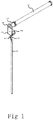
FIG. 1 is a stereogram of the reel pipe motor according to a preferred embodiment of the invention; -
FIG. 2 is an exploded view of the reel pipe motor according to a preferred embodiment of the invention; -
FIG. 3 is an exploded view of the motor end head according to a preferred embodiment of the invention; -
FIG. 4 is a stereogram of the conic contact according to a preferred embodiment of the invention; -
FIG. 5 is another stereogram of the conic contact according to a preferred embodiment of the invention; -
FIG. 6 is an exploded view of the speed reduction assembly according to a preferred embodiment of the invention; and -
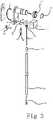
FIG. 7 is a stereogram of the rolling curtain positioning control system according to a preferred embodiment of the invention. - Embodiments of the present invention will be described in detail below with reference to the drawings. However, the present invention shall not be limited to these embodiments.
- With reference to
figs. 1 and2 , the reel pipe motor of the invention comprises acasing 100; amotor 200 and aspeed reduction assembly 300 disposed within thecasing 100; an L-shapemotor end head 400 having atubular part 410 and abox part 420 which could be connected with the casing; aswitch box 500 disposed on the outer surface of the box part, in which aswitch control panel 510 and abead switch 520 are located; apower supply plug 600 and ahollow rod 700. Thebead switch 520 is connected with thehollow rod 700. Thebead switch 520 could be operated by pulling thehollow rod 700. The first end of thepower supply plug 600 is electrically connected with theswitch control panel 510 and the second end thereof extends into thehollow rod 700 and is electrically connected with an external power supply. - The movement of the motor could be controlled by pulling the
bead switch 520, so that the activation and disenablement of the reel pipe motor could be more simply controlled and more smoothly operated. - One end of the
power supply plug 600 for connecting to the external power supply is inserted onto the switch control panel, and the wire connected with the other end thereof extends into the hollow rod and is then electrically connected with the external power supply. Theexternal power line 10 electrically connected to the motor passes through the tubular part and box part of the motor end head and then is electrically connected with the switch control panel. A viahole 421 is located on the box part for passing theexternal power line 10. As the wire of thepower supply plug 600 and theexternal power line 10 electrically connected to the motor respectively hide within the hollow rod and the motor end head, the reel pipe motor has a more aesthetic overall appearance. - Referring to
figs. 4-5 , in a preferred embodiment, thebead switch 520 is composed of a main body 512 electrically connected with the switch control panel and a bead chain 522. Thehollow rod 700 is composed of aconic contact 710 and a hollowcylindrical tube 720 connected with theconic contact 710. Apower supply socket 730 is inserted at the bottom of the hollowcylindrical tube 720 for inserting the external power supply. - A first via
hole 711 having a diameter smaller than that of the bead of the bead chain, is formed on the top surface of theconic contact 710. A second viahole 712 having a diameter larger than that of the bead of the bead chain is formed on the first side of the conic contact. The first via hole is in communication with the second via hole by the connectingseam 713. - The bead at the end of the bead chain extends into the second via
hole 712 and then moves to the lower end of the first viahole 711 along the connectingseam 713, thereby limiting the bead chain at the lower end of the first viahole 711. - A third via
hole 714 is formed on the second side of theconic contact 710. The third via hole is substantially of a water-drop shape. The wire of the power supply plug extends into the hollow cylindrical tube through the third viahole 714. - Referring to
fig. 2 , in this embodiment, not only themotor 200 and thespeed reduction assembly 300 are located within thecasing 100, but also the chargingbattery 20 and the chargecontrol circuit board 30 are provided. Theexternal power line 10, the chargingbattery 20 and themotor 200 are all electrically connected with the chargecontrol circuit board 30. When the external power supply is transferred to the chargecontrol circuit board 30 through theexternal power line 10, the chargecontrol circuit board 30 transfers the external power supply to the charging battery and the motor respectively. When no external power supply is detected by the charge control circuit board, current is provided by the chargingbattery 20 to themotor 200. - A
crown wheel 411 and aclamp 412 preventing thecrown wheel 411 from falling off the outer surface of the tubular part are covered on the outer surface of thetubular part 410 of the motor end head. - A
rotation wheel 40 is provided on the other end of the casing. Therotation wheel 40 is connected with the output end of the speed reduction assembly. - As shown in
fig. 6 , thespeed reduction assembly 300 according to this embodiment comprises aworm 310 connected with the output shaft of the motor, a plurality of cone pulleys and conic wheels engaged with each other. The rotation speed of the motor is transmitted to through the worm and reduced by the plurality of cone pulleys, and then transmitted to the conic wheels. - In this embodiment, the first, second, third, fourth and fifth cone pulleys are provided, in which the gear ratio of the worm to the
first cone pulley 320 is 15-20, the gear ratio of thefirst cone pulley 320 to thesecond cone pulley 330 is 2-5, the gear ratio of thesecond cone pulley 330 to thethird cone pulley 340 is 10/(3-4), the gear ratio of thethird cone pulley 340 to thefourth cone pulley 350 is 2.5-3, thefourth cone pulley 350 drives thefifth cone pulley 360, thefifth cone pulley 360 drives theconic wheel 370, and the gear ratio of thefifth cone pulley 360 to theconic wheel 370 is 800/(3-5). - The cone pulley configuration makes full use of the space of the reel pipe, which effectively shortens the length and reduces the volume.
- The
first cone pulley 320 is configured by a helical gear and a spur gear. Thefifth cone pulley 360 is configured by a bevel gear and a spur gear. All the second, third and fourth cone pulleys are configured by two spur gears. The first and fifth cone pulleys are configured to cooperate with the worm and the conic wheel. - The speed reduction assembly further comprises a speed reduction gearbox
upper casing 311, a speed reduction gearboxlower casing 312, a speedreduction gearbox cap 313 and abearing 314. The speed reduction gearboxupper casing 311, the speed reduction gearboxlower casing 312, the speedreduction gearbox cap 313 and thebearing 314 are formed to receive the speed reduction configuration including the cone pulleys, wheels and worm. - Referring to
fig. 7 , the present invention further discloses a rolling curtain positioning system comprising the aforesaid reel pipe motor andcurtain cloth 1000. Thecurtain cloth 1000 could be wound onto the reel pipe under the action of the reel pipe motor. - A starting
end sensing element 1001 and a terminating end sensing element 1002 are respectively provided on two ends of the curtain cloth. A sensor not shown is disposed at the switch control panel within the switch box. When the curtain cloth is wound up, the reel pipe motor is stopped after the sensor senses the terminating end sensing element 1002. When the curtain cloth is wound down, the reel pipe motor is stopped after the sensor senses the startingend sensing element 1001. - When the curtain cloth is wound up, after the reel pipe motor is stopped following the sensor senses the terminating end sensing element 1002, the reel pipe motor will not run even if the instruction to wind up the curtain cloth is executed again. By the same token, when the curtain cloth is wound down, after the reel pipe motor is stopped following the sensor senses the starting
end sensing element 1001, the reel pipe motor will not run even if the instruction to wind down the curtain cloth is executed again. - The sensor and sensing elements in this invention could employ infrared sense or Holzer magnetic induction. In a preferred embodiment, the starting
end sensing element 1001 and the terminating end sensing element 1002 are both magnets, and the sensor could include a tongue tube and the tongue tube could detect magnets and cut off circuit connection. - In order to reduce shake of the curtain cloth while being wound up and down, a
level rod 422 is further provided on the side of the box part. - The specific embodiments described herein are merely illustrative of the spirit of the invention. It is apparent to those skilled in the art that various modifications, amendments and alternatives can be made to these embodiments without departing from the spirit or scope defined by the appended claims.
Claims (15)
- A reel pipe motor, comprising:a casing;a motor and a speed reduction assembly disposed within the casing;an L-shape motor end head having a tubular part and a box part which could be connected with the casing;a switch box disposed on the outer surface of the box part, in which a switch control panel and a bead switch are located; anda power supply plug and a hollow rod,in which the bead switch is connected with the hollow rod, the bead switch could be operated by pulling the hollow rod, a first end of the power supply plug is electrically connected with the switch control panel and a second end thereof extends into the hollow rod and is electrically connected with an external power supply.
- The reel pipe motor as claimed in Claim 1, characterized in that, a charge control circuit board as well as an external power line and a charging battery connected with the charge control circuit board are further provided within the casing; the external power line is electrically connected with the switch control panel after passing through the tubular part and the box part; the charge control circuit board is electrically connected with the motor; and when the external power supply is turned on, the charging battery is charged by the external power supply when it drives the motor into operation, and when the external power supply is cut off, the motor is driven into operation by the charging battery.
- The reel pipe motor as claimed in Claim 1, characterized in that, a power supply socket is further provided at the end of the hollow rod for inserting the external power supply.
- The reel pipe motor as claimed in Claim 1, characterized in that, a crown wheel and a clamp preventing the crown wheel from falling off the outer surface of the tubular part are covered on the outer surface of the tubular part.
- The reel pipe motor as claimed in Claim 1, characterized in that, further comprising a rotation wheel which is connected with the speed reduction assembly.
- The reel pipe motor as claimed in Claim 1, characterized in that, the bead switch includes a main body electrically connected with the switch control panel and a bead chain extending into the main body; the hollow rod includes a conic contact and a hollow cylindrical tube connected with the conic contact; and the bead chain extends into and is limited within the conic contact.
- The reel pipe motor as claimed in Claim 6, characterized in that, a first via hole having a diameter smaller than that of the bead of the bead chain, is formed on the top surface of the conic contact, a second via hole having a diameter larger than that of the bead of the bead chain is formed on the first side of the conic contact, and the first via hole is in communication with the second via hole by a connecting seam.
- The reel pipe motor as claimed in Claim 7, characterized in that, a third via hole is formed on the second side of the conic contact, and a second end of the power supply plug extends into the hollow cylindrical tube through the third via hole.
- The reel pipe motor as claimed in Claim 1, characterized in that, the speed reduction assembly includes a worm connected with an output shaft of the motor; a plurality of cone pulleys and conic wheels engaged with each other; and the rotation speed of the motor is transmitted to through the worm and reduced by the plurality of cone pulleys, and then transmitted to the conic wheels.
- The reel pipe motor as claimed in Claim 9, characterized in that, the plurality of cone pulleys includes first, second, third, fourth and fifth cone pulleys, in which the gear ratio of the worm to the first cone pulley is 15-20, the gear ratio of the first cone pulley to the second cone pulley is 2-5, the gear ratio of the second cone pulley to the third cone pulley is 10/(3-4), the gear ratio of the third cone pulley to the fourth cone pulley 350 is 2.5-3, the fourth cone pulley drives the fifth cone pulley, the fifth cone pulley drives the conic wheel, and the gear ratio of the fifth cone pulley to the conic wheel is 800/(3-5).
- The reel pipe motor as claimed in Claim 10, characterized in that, the first cone pulley is configured by a helical gear and a spur gear, the fifth cone pulley is configured by a bevel gear and a spur gear, and all the second, third and fourth cone pulleys are configured by two spur gears.
- The reel pipe motor as claimed in Claim 1, characterized in that, a sensor is further provided at the switch control panel and when the sensor senses a target to be sensed, the circuit control panel turns on or off the power supply.
- The reel pipe motor as claimed in Claim 1, characterized in that, a level rod is further provided on the side of the box part.
- A rolling curtain positioning control system, characterized in that, comprising the reel pipe motor as claimed in any one of Claims 1-13, further comprising curtain cloth, in which a starting end sensing element and a terminating end sensing element are respectively provided on two ends of the curtain cloth, when the curtain cloth is wound up, the reel pipe motor is stopped after the switch control panel senses the terminating end sensing element, and when the curtain cloth is wound down, the reel pipe motor is stopped after the switch control panel senses the starting end sensing element.
- The rolling curtain positioning control system as claimed in Claim 14, characterized in that, the starting end sensing element and the terminating end sensing element are both magnets, and a tongue tube is provided on the switch control panel.
Applications Claiming Priority (4)
| Application Number | Priority Date | Filing Date | Title |
|---|---|---|---|
| CN201510314151.9A CN104895478A (en) | 2015-06-09 | 2015-06-09 | Electric roller shutter positioning control system |
| CN201520615588.1U CN204941310U (en) | 2015-08-14 | 2015-08-14 | A kind of dual power supply electric rolling positioning control structure and system |
| CN201510556049.XA CN105119426A (en) | 2015-09-02 | 2015-09-02 | Deceleration tubular motor having rechargeable battery |
| PCT/CN2015/092892 WO2016197520A1 (en) | 2015-06-09 | 2015-10-27 | Roller tube electrical motor and roller shade positioning control system |
Publications (3)
| Publication Number | Publication Date |
|---|---|
| EP3128115A1 true EP3128115A1 (en) | 2017-02-08 |
| EP3128115A4 EP3128115A4 (en) | 2017-04-19 |
| EP3128115B1 EP3128115B1 (en) | 2018-04-04 |
Family
ID=57132944
Family Applications (1)
| Application Number | Title | Priority Date | Filing Date |
|---|---|---|---|
| EP15822899.9A Active EP3128115B1 (en) | 2015-06-09 | 2015-10-27 | Roller tube electrical motor and roller shade positioning control system |
Country Status (9)
| Country | Link |
|---|---|
| US (1) | US9840870B2 (en) |
| EP (1) | EP3128115B1 (en) |
| AU (1) | AU2015291796B8 (en) |
| CA (1) | CA2917665C (en) |
| ES (1) | ES2671130T3 (en) |
| NZ (1) | NZ715994A (en) |
| PT (1) | PT3128115T (en) |
| SG (1) | SG11201601325QA (en) |
| WO (1) | WO2016197520A1 (en) |
Cited By (4)
| Publication number | Priority date | Publication date | Assignee | Title |
|---|---|---|---|---|
| US20170268293A1 (en) * | 2016-03-17 | 2017-09-21 | Coulisse B.V. | Device for manually operating a motorized drive of a screen, such as a window covering, and method for saving setting values associated with different positions of the screen |
| EP3401494A1 (en) | 2017-04-17 | 2018-11-14 | Nien Made Enterprise Co., Ltd. | Charging system for electric window covering |
| EP3828374A1 (en) | 2019-11-28 | 2021-06-02 | Nien Made Enterprise Co., Ltd. | Charging system for electric window covering |
| US11146085B2 (en) | 2017-04-17 | 2021-10-12 | Nien Made Enterprise Co., Ltd. | Charging system for electric window covering |
Families Citing this family (18)
| Publication number | Priority date | Publication date | Assignee | Title |
|---|---|---|---|---|
| US10851587B2 (en) | 2016-10-19 | 2020-12-01 | Hunter Douglas Inc. | Motor assemblies for architectural coverings |
| USD874183S1 (en) | 2017-05-19 | 2020-02-04 | Lutron Technology Company Llc | Bracket cover applied to a window treatment |
| USD943401S1 (en) * | 2017-04-28 | 2022-02-15 | Lutron Technology Company Llc | Window treatment |
| US11957261B2 (en) | 2017-04-28 | 2024-04-16 | Lutron Technology Company Llc | Window treatment mounting bracket |
| USD871795S1 (en) | 2017-04-28 | 2020-01-07 | Lutron Technology Company Llc | Hem bar applied to a window treatment |
| USD871105S1 (en) | 2017-05-03 | 2019-12-31 | Lutron Technology Company Llc | Hem bar applied to a window treament |
| USD883776S1 (en) | 2017-09-01 | 2020-05-12 | Lutron Technology Company Llc | Bracket applied to a window treatment |
| JP7033380B2 (en) * | 2018-05-30 | 2022-03-10 | 立川ブラインド工業株式会社 | Electric cloaking device |
| US11486198B2 (en) | 2019-04-19 | 2022-11-01 | Hunter Douglas Inc. | Motor assemblies for architectural coverings |
| CN110374485A (en) * | 2019-07-04 | 2019-10-25 | 佛山科学技术学院 | A kind of intelligent window |
| CN110242199A (en) * | 2019-07-08 | 2019-09-17 | 诚宝帘盟(广东)遮阳科技有限公司 | A kind of Multifunctional wind roller shutter |
| USD949596S1 (en) * | 2019-11-25 | 2022-04-26 | Fourds Limited | Indoor blind |
| USD953148S1 (en) | 2020-08-14 | 2022-05-31 | Lutron Technology Company Llc | Bracket applied to a window treatment |
| USD953847S1 (en) | 2020-09-04 | 2022-06-07 | Lutron Technology Company Llc | Bracket applied to a window treatment |
| USD962044S1 (en) | 2021-02-26 | 2022-08-30 | Lutron Technology Company Llc | Bracket applied to a window treatment |
| USD962043S1 (en) | 2021-02-26 | 2022-08-30 | Lutron Technology Company Llc | Bracket applied to a window treatment |
| USD1008785S1 (en) | 2022-02-28 | 2023-12-26 | Lutron Technology Company Llc | Bracket set applied to a window treatment |
| USD1006611S1 (en) | 2022-02-28 | 2023-12-05 | Lutron Technology Company Llc | Bracket applied to a window treatment |
Family Cites Families (23)
| Publication number | Priority date | Publication date | Assignee | Title |
|---|---|---|---|---|
| WO1986002970A1 (en) * | 1984-11-16 | 1986-05-22 | Donald Lawrence Glatzel | Motorised roller blinds |
| EP0852281A3 (en) | 1997-01-07 | 2000-03-08 | Joaquin Fondevilla Calderon | Electric engine control electronic board |
| WO2001069030A1 (en) * | 2000-03-15 | 2001-09-20 | Viktor Alexeevich Evseenkov | Driven blind |
| FR2840012B1 (en) * | 2002-05-22 | 2004-08-13 | Zurfluh Feller | ELECTROMECHANICAL DRIVE DEVICE FOR ROLLER SHUTTER |
| TWM245911U (en) * | 2003-07-16 | 2004-10-11 | Nien Made Entpr Co Ltd | Electric curtain easy in replacing batteries |
| US20060232233A1 (en) * | 2005-04-01 | 2006-10-19 | Adams Jason O | Drive assembly for a motorized roller tube system |
| US7880409B2 (en) * | 2005-09-19 | 2011-02-01 | Qualitas Manufacturing Inc. | Removable power supply for a motorized shutter assembly |
| ITMC20050133A1 (en) * | 2005-12-13 | 2007-06-14 | Gaposa Srl | EPICYCLOIDAL REDUCER WITH MORE MODULAR STAGES FOR TUBULAR GEARED MOTORS OF ROLLER SHUTTERS, ROLLERS AND THE LIKE. |
| ITMI20070492A1 (en) * | 2007-03-13 | 2008-09-14 | Faac Spa | ADAPTABLE TUBULAR ELECTRIC MOTOR ASSEMBLY FOR ROLLING SHUTTERS SUCH AS SHUTTERS AND THE LIKE. |
| CN201018345Y (en) | 2007-04-06 | 2008-02-06 | 华林 | Novel tube-type electric motor |
| GB2463235A (en) * | 2008-09-03 | 2010-03-10 | Johnson Electric Sa | Controller for roller driver DC electric motor |
| US20100307701A1 (en) * | 2009-06-09 | 2010-12-09 | Thomas Peterson | Integrated quiet Motorized Roller Shade System |
| US20110017411A1 (en) * | 2009-07-22 | 2011-01-27 | Bin Terng Enterprise Co., Ltd. | Electric curtain via accurately controlling a stop position of its covering sheet |
| TWM373190U (en) | 2009-08-13 | 2010-02-01 | My Home Global Co | Fixing device for bead chain chord of window curtain |
| CN201495972U (en) * | 2009-10-09 | 2010-06-02 | 李凤剑 | Reeling type sunshade curtain |
| US9151110B2 (en) * | 2010-03-02 | 2015-10-06 | Safe-T-Shade | Cordless blind systems having cord enclosures with a swivel feature and methods of assembling such cord enclosures |
| US8692498B2 (en) * | 2010-08-30 | 2014-04-08 | Crestron Electronics Inc. | System and method for controlling one or more roller shades |
| CN101994478B (en) * | 2010-10-19 | 2012-05-16 | 中国科学院广州能源研究所 | Invisible intelligent full-automatic outer sun-shading system |
| CN103628782B (en) | 2013-12-11 | 2015-11-11 | 吴小国 | The double-layer glass Thermal insulation door and window of built-in roller shutter |
| CN104265147B (en) * | 2014-09-16 | 2016-01-20 | 宁波先锋新材料股份有限公司 | A kind of electric sunshading curtain and control method thereof |
| CN204532011U (en) | 2015-03-23 | 2015-08-05 | 高树立 | A kind of tube shaped electric machine for electric rolling |
| CN104895478A (en) | 2015-06-09 | 2015-09-09 | 宁波先锋新材料股份有限公司 | Electric roller shutter positioning control system |
| CN104989259A (en) | 2015-07-23 | 2015-10-21 | 宁波先锋新材料股份有限公司 | Integrated roller shutter window with positioning control system |
-
2015
- 2015-10-27 WO PCT/CN2015/092892 patent/WO2016197520A1/en active Application Filing
- 2015-10-27 EP EP15822899.9A patent/EP3128115B1/en active Active
- 2015-10-27 PT PT158228999T patent/PT3128115T/en unknown
- 2015-10-27 US US14/905,804 patent/US9840870B2/en active Active
- 2015-10-27 AU AU2015291796A patent/AU2015291796B8/en not_active Ceased
- 2015-10-27 ES ES15822899.9T patent/ES2671130T3/en active Active
- 2015-10-27 NZ NZ715994A patent/NZ715994A/en not_active IP Right Cessation
- 2015-10-27 CA CA2917665A patent/CA2917665C/en not_active Expired - Fee Related
- 2015-10-27 SG SG11201601325QA patent/SG11201601325QA/en unknown
Cited By (9)
| Publication number | Priority date | Publication date | Assignee | Title |
|---|---|---|---|---|
| US20170268293A1 (en) * | 2016-03-17 | 2017-09-21 | Coulisse B.V. | Device for manually operating a motorized drive of a screen, such as a window covering, and method for saving setting values associated with different positions of the screen |
| US10633917B2 (en) * | 2016-03-17 | 2020-04-28 | Coulisse B.V. | Device for manually operating a motorized drive of a screen, such as a window covering, and method for saving setting values associated with different positions of the screen |
| EP3401494A1 (en) | 2017-04-17 | 2018-11-14 | Nien Made Enterprise Co., Ltd. | Charging system for electric window covering |
| EP3575541A1 (en) | 2017-04-17 | 2019-12-04 | Nien Made Enterprise Co., Ltd. | Charging system for electric window covering |
| EP3575540A1 (en) | 2017-04-17 | 2019-12-04 | Nien Made Enterprise Co., Ltd. | Charging system for electric window covering |
| US10847983B2 (en) | 2017-04-17 | 2020-11-24 | Nien Made Enterprise Co., Ltd. | Charging system for electric window covering and method of charging electric window covering with the same |
| US11146085B2 (en) | 2017-04-17 | 2021-10-12 | Nien Made Enterprise Co., Ltd. | Charging system for electric window covering |
| US11223218B2 (en) | 2017-04-17 | 2022-01-11 | Nien Made Enterprise Co., Ltd. | Electric window covering and charging system therefor |
| EP3828374A1 (en) | 2019-11-28 | 2021-06-02 | Nien Made Enterprise Co., Ltd. | Charging system for electric window covering |
Also Published As
| Publication number | Publication date |
|---|---|
| AU2015291796B8 (en) | 2017-10-26 |
| SG11201601325QA (en) | 2017-01-27 |
| CA2917665C (en) | 2017-08-22 |
| CA2917665A1 (en) | 2016-12-09 |
| NZ715994A (en) | 2018-12-21 |
| PT3128115T (en) | 2018-06-28 |
| EP3128115B1 (en) | 2018-04-04 |
| AU2015291796A8 (en) | 2017-10-26 |
| AU2015291796A1 (en) | 2017-01-05 |
| US20170183908A1 (en) | 2017-06-29 |
| WO2016197520A1 (en) | 2016-12-15 |
| AU2015291796B2 (en) | 2017-04-27 |
| ES2671130T3 (en) | 2018-06-05 |
| EP3128115A4 (en) | 2017-04-19 |
| US9840870B2 (en) | 2017-12-12 |
Similar Documents
| Publication | Publication Date | Title |
|---|---|---|
| AU2015291796B8 (en) | A reel pipe motor and a rolling curtain positioning control system | |
| EP2987712B9 (en) | Electric balance scooter | |
| CN104733947B (en) | Coiling device and household appliance with same | |
| US10723601B2 (en) | Winch and fairlead with a detachable line guide | |
| CN104895478A (en) | Electric roller shutter positioning control system | |
| US11485618B2 (en) | Motor-driven fairlead to aid in spooling or unspooling a line from a winch | |
| CN207972542U (en) | A kind of electric vehicle new energy charging pile | |
| CN103928812B (en) | A kind of special cleaning machine of electrical automobile charging plug | |
| CN203692247U (en) | Wire guide device for wire spool | |
| CN201772826U (en) | Electric tapeline | |
| WO2023130692A1 (en) | Manual-automatic integrated sunshade blind | |
| CN106895375B (en) | A kind of LED | |
| KR101657911B1 (en) | Electrical lifting blackboard apparatus | |
| CN204941310U (en) | A kind of dual power supply electric rolling positioning control structure and system | |
| CN103405932B (en) | One is bolted wheel | |
| CN105257202A (en) | Automatic curtain based on Internet of things | |
| CN204677101U (en) | A kind of electric rolling positioning control system | |
| CN104989259A (en) | Integrated roller shutter window with positioning control system | |
| CN107706643A (en) | A kind of novel electric power power supply plug assembly | |
| CN107248646A (en) | A kind of multifunctional portable power source patch board | |
| CN203833381U (en) | Paying-off machine | |
| CN109432617B (en) | Fire auxiliary rescue unmanned aerial vehicle | |
| CN110898440B (en) | Portable remote control unmanned ship | |
| CN110867775A (en) | Light current construction winding displacement device | |
| CN207792322U (en) | A kind of line winder |
Legal Events
| Date | Code | Title | Description |
|---|---|---|---|
| STAA | Information on the status of an ep patent application or granted ep patent |
Free format text: STATUS: UNKNOWN |
|
| STAA | Information on the status of an ep patent application or granted ep patent |
Free format text: STATUS: THE INTERNATIONAL PUBLICATION HAS BEEN MADE |
|
| PUAI | Public reference made under article 153(3) epc to a published international application that has entered the european phase |
Free format text: ORIGINAL CODE: 0009012 |
|
| STAA | Information on the status of an ep patent application or granted ep patent |
Free format text: STATUS: REQUEST FOR EXAMINATION WAS MADE |
|
| 17P | Request for examination filed |
Effective date: 20160122 |
|
| AK | Designated contracting states |
Kind code of ref document: A1 Designated state(s): AL AT BE BG CH CY CZ DE DK EE ES FI FR GB GR HR HU IE IS IT LI LT LU LV MC MK MT NL NO PL PT RO RS SE SI SK SM TR |
|
| AX | Request for extension of the european patent |
Extension state: BA ME |
|
| REG | Reference to a national code |
Ref country code: DE Ref legal event code: R079 Ref document number: 602015009693 Country of ref document: DE Free format text: PREVIOUS MAIN CLASS: E06B0009420000 Ipc: E06B0009400000 |
|
| A4 | Supplementary search report drawn up and despatched |
Effective date: 20170321 |
|
| RIC1 | Information provided on ipc code assigned before grant |
Ipc: E06B 9/50 20060101ALI20170315BHEP Ipc: E06B 9/72 20060101ALI20170315BHEP Ipc: E06B 9/40 20060101AFI20170315BHEP Ipc: E06B 9/68 20060101ALI20170315BHEP Ipc: E06B 9/42 20060101ALI20170315BHEP |
|
| GRAP | Despatch of communication of intention to grant a patent |
Free format text: ORIGINAL CODE: EPIDOSNIGR1 |
|
| STAA | Information on the status of an ep patent application or granted ep patent |
Free format text: STATUS: GRANT OF PATENT IS INTENDED |
|
| DAX | Request for extension of the european patent (deleted) | ||
| INTG | Intention to grant announced |
Effective date: 20171207 |
|
| GRAS | Grant fee paid |
Free format text: ORIGINAL CODE: EPIDOSNIGR3 |
|
| GRAA | (expected) grant |
Free format text: ORIGINAL CODE: 0009210 |
|
| STAA | Information on the status of an ep patent application or granted ep patent |
Free format text: STATUS: THE PATENT HAS BEEN GRANTED |
|
| AK | Designated contracting states |
Kind code of ref document: B1 Designated state(s): AL AT BE BG CH CY CZ DE DK EE ES FI FR GB GR HR HU IE IS IT LI LT LU LV MC MK MT NL NO PL PT RO RS SE SI SK SM TR |
|
| DAV | Request for validation of the european patent (deleted) | ||
| REG | Reference to a national code |
Ref country code: GB Ref legal event code: FG4D |
|
| REG | Reference to a national code |
Ref country code: CH Ref legal event code: EP |
|
| REG | Reference to a national code |
Ref country code: AT Ref legal event code: REF Ref document number: 985794 Country of ref document: AT Kind code of ref document: T Effective date: 20180415 |
|
| REG | Reference to a national code |
Ref country code: IE Ref legal event code: FG4D |
|
| REG | Reference to a national code |
Ref country code: DE Ref legal event code: R096 Ref document number: 602015009693 Country of ref document: DE |
|
| REG | Reference to a national code |
Ref country code: ES Ref legal event code: FG2A Ref document number: 2671130 Country of ref document: ES Kind code of ref document: T3 Effective date: 20180605 |
|
| REG | Reference to a national code |
Ref country code: PT Ref legal event code: SC4A Ref document number: 3128115 Country of ref document: PT Date of ref document: 20180628 Kind code of ref document: T Free format text: AVAILABILITY OF NATIONAL TRANSLATION Effective date: 20180622 |
|
| REG | Reference to a national code |
Ref country code: NL Ref legal event code: FP |
|
| REG | Reference to a national code |
Ref country code: LT Ref legal event code: MG4D |
|
| REG | Reference to a national code |
Ref country code: FR Ref legal event code: PLFP Year of fee payment: 4 |
|
| PG25 | Lapsed in a contracting state [announced via postgrant information from national office to epo] |
Ref country code: SE Free format text: LAPSE BECAUSE OF FAILURE TO SUBMIT A TRANSLATION OF THE DESCRIPTION OR TO PAY THE FEE WITHIN THE PRESCRIBED TIME-LIMIT Effective date: 20180404 Ref country code: AL Free format text: LAPSE BECAUSE OF FAILURE TO SUBMIT A TRANSLATION OF THE DESCRIPTION OR TO PAY THE FEE WITHIN THE PRESCRIBED TIME-LIMIT Effective date: 20180404 Ref country code: FI Free format text: LAPSE BECAUSE OF FAILURE TO SUBMIT A TRANSLATION OF THE DESCRIPTION OR TO PAY THE FEE WITHIN THE PRESCRIBED TIME-LIMIT Effective date: 20180404 Ref country code: BG Free format text: LAPSE BECAUSE OF FAILURE TO SUBMIT A TRANSLATION OF THE DESCRIPTION OR TO PAY THE FEE WITHIN THE PRESCRIBED TIME-LIMIT Effective date: 20180704 Ref country code: NO Free format text: LAPSE BECAUSE OF FAILURE TO SUBMIT A TRANSLATION OF THE DESCRIPTION OR TO PAY THE FEE WITHIN THE PRESCRIBED TIME-LIMIT Effective date: 20180704 Ref country code: PL Free format text: LAPSE BECAUSE OF FAILURE TO SUBMIT A TRANSLATION OF THE DESCRIPTION OR TO PAY THE FEE WITHIN THE PRESCRIBED TIME-LIMIT Effective date: 20180404 Ref country code: LT Free format text: LAPSE BECAUSE OF FAILURE TO SUBMIT A TRANSLATION OF THE DESCRIPTION OR TO PAY THE FEE WITHIN THE PRESCRIBED TIME-LIMIT Effective date: 20180404 |
|
| PG25 | Lapsed in a contracting state [announced via postgrant information from national office to epo] |
Ref country code: HR Free format text: LAPSE BECAUSE OF FAILURE TO SUBMIT A TRANSLATION OF THE DESCRIPTION OR TO PAY THE FEE WITHIN THE PRESCRIBED TIME-LIMIT Effective date: 20180404 Ref country code: LV Free format text: LAPSE BECAUSE OF FAILURE TO SUBMIT A TRANSLATION OF THE DESCRIPTION OR TO PAY THE FEE WITHIN THE PRESCRIBED TIME-LIMIT Effective date: 20180404 Ref country code: RS Free format text: LAPSE BECAUSE OF FAILURE TO SUBMIT A TRANSLATION OF THE DESCRIPTION OR TO PAY THE FEE WITHIN THE PRESCRIBED TIME-LIMIT Effective date: 20180404 |
|
| PGFP | Annual fee paid to national office [announced via postgrant information from national office to epo] |
Ref country code: NL Payment date: 20181024 Year of fee payment: 4 |
|
| REG | Reference to a national code |
Ref country code: DE Ref legal event code: R097 Ref document number: 602015009693 Country of ref document: DE |
|
| REG | Reference to a national code |
Ref country code: GR Ref legal event code: EP Ref document number: 20180401848 Country of ref document: GR Effective date: 20190109 |
|
| PG25 | Lapsed in a contracting state [announced via postgrant information from national office to epo] |
Ref country code: CZ Free format text: LAPSE BECAUSE OF FAILURE TO SUBMIT A TRANSLATION OF THE DESCRIPTION OR TO PAY THE FEE WITHIN THE PRESCRIBED TIME-LIMIT Effective date: 20180404 Ref country code: RO Free format text: LAPSE BECAUSE OF FAILURE TO SUBMIT A TRANSLATION OF THE DESCRIPTION OR TO PAY THE FEE WITHIN THE PRESCRIBED TIME-LIMIT Effective date: 20180404 Ref country code: EE Free format text: LAPSE BECAUSE OF FAILURE TO SUBMIT A TRANSLATION OF THE DESCRIPTION OR TO PAY THE FEE WITHIN THE PRESCRIBED TIME-LIMIT Effective date: 20180404 Ref country code: DK Free format text: LAPSE BECAUSE OF FAILURE TO SUBMIT A TRANSLATION OF THE DESCRIPTION OR TO PAY THE FEE WITHIN THE PRESCRIBED TIME-LIMIT Effective date: 20180404 Ref country code: SK Free format text: LAPSE BECAUSE OF FAILURE TO SUBMIT A TRANSLATION OF THE DESCRIPTION OR TO PAY THE FEE WITHIN THE PRESCRIBED TIME-LIMIT Effective date: 20180404 |
|
| PGFP | Annual fee paid to national office [announced via postgrant information from national office to epo] |
Ref country code: GR Payment date: 20181031 Year of fee payment: 4 Ref country code: DE Payment date: 20181024 Year of fee payment: 4 |
|
| PLBE | No opposition filed within time limit |
Free format text: ORIGINAL CODE: 0009261 |
|
| STAA | Information on the status of an ep patent application or granted ep patent |
Free format text: STATUS: NO OPPOSITION FILED WITHIN TIME LIMIT |
|
| PG25 | Lapsed in a contracting state [announced via postgrant information from national office to epo] |
Ref country code: SM Free format text: LAPSE BECAUSE OF FAILURE TO SUBMIT A TRANSLATION OF THE DESCRIPTION OR TO PAY THE FEE WITHIN THE PRESCRIBED TIME-LIMIT Effective date: 20180404 |
|
| PGFP | Annual fee paid to national office [announced via postgrant information from national office to epo] |
Ref country code: FR Payment date: 20181011 Year of fee payment: 4 Ref country code: ES Payment date: 20181109 Year of fee payment: 4 Ref country code: IT Payment date: 20181031 Year of fee payment: 4 Ref country code: CH Payment date: 20181026 Year of fee payment: 4 Ref country code: BE Payment date: 20181026 Year of fee payment: 4 |
|
| 26N | No opposition filed |
Effective date: 20190107 |
|
| PG25 | Lapsed in a contracting state [announced via postgrant information from national office to epo] |
Ref country code: SI Free format text: LAPSE BECAUSE OF FAILURE TO SUBMIT A TRANSLATION OF THE DESCRIPTION OR TO PAY THE FEE WITHIN THE PRESCRIBED TIME-LIMIT Effective date: 20180404 |
|
| PG25 | Lapsed in a contracting state [announced via postgrant information from national office to epo] |
Ref country code: MC Free format text: LAPSE BECAUSE OF FAILURE TO SUBMIT A TRANSLATION OF THE DESCRIPTION OR TO PAY THE FEE WITHIN THE PRESCRIBED TIME-LIMIT Effective date: 20180404 Ref country code: LU Free format text: LAPSE BECAUSE OF NON-PAYMENT OF DUE FEES Effective date: 20181027 |
|
| REG | Reference to a national code |
Ref country code: IE Ref legal event code: MM4A |
|
| PG25 | Lapsed in a contracting state [announced via postgrant information from national office to epo] |
Ref country code: PT Free format text: LAPSE BECAUSE OF NON-PAYMENT OF DUE FEES Effective date: 20190729 Ref country code: IE Free format text: LAPSE BECAUSE OF NON-PAYMENT OF DUE FEES Effective date: 20181027 |
|
| PG25 | Lapsed in a contracting state [announced via postgrant information from national office to epo] |
Ref country code: MT Free format text: LAPSE BECAUSE OF NON-PAYMENT OF DUE FEES Effective date: 20181027 |
|
| PG25 | Lapsed in a contracting state [announced via postgrant information from national office to epo] |
Ref country code: TR Free format text: LAPSE BECAUSE OF FAILURE TO SUBMIT A TRANSLATION OF THE DESCRIPTION OR TO PAY THE FEE WITHIN THE PRESCRIBED TIME-LIMIT Effective date: 20180404 |
|
| REG | Reference to a national code |
Ref country code: DE Ref legal event code: R119 Ref document number: 602015009693 Country of ref document: DE |
|
| REG | Reference to a national code |
Ref country code: CH Ref legal event code: PL |
|
| REG | Reference to a national code |
Ref country code: NL Ref legal event code: MM Effective date: 20191101 |
|
| PG25 | Lapsed in a contracting state [announced via postgrant information from national office to epo] |
Ref country code: CY Free format text: LAPSE BECAUSE OF FAILURE TO SUBMIT A TRANSLATION OF THE DESCRIPTION OR TO PAY THE FEE WITHIN THE PRESCRIBED TIME-LIMIT Effective date: 20180404 Ref country code: HU Free format text: LAPSE BECAUSE OF FAILURE TO SUBMIT A TRANSLATION OF THE DESCRIPTION OR TO PAY THE FEE WITHIN THE PRESCRIBED TIME-LIMIT; INVALID AB INITIO Effective date: 20151027 Ref country code: MK Free format text: LAPSE BECAUSE OF NON-PAYMENT OF DUE FEES Effective date: 20180404 |
|
| REG | Reference to a national code |
Ref country code: AT Ref legal event code: UEP Ref document number: 985794 Country of ref document: AT Kind code of ref document: T Effective date: 20180404 |
|
| PG25 | Lapsed in a contracting state [announced via postgrant information from national office to epo] |
Ref country code: GR Free format text: LAPSE BECAUSE OF NON-PAYMENT OF DUE FEES Effective date: 20200506 Ref country code: CH Free format text: LAPSE BECAUSE OF NON-PAYMENT OF DUE FEES Effective date: 20191031 Ref country code: LI Free format text: LAPSE BECAUSE OF NON-PAYMENT OF DUE FEES Effective date: 20191031 Ref country code: DE Free format text: LAPSE BECAUSE OF NON-PAYMENT OF DUE FEES Effective date: 20200501 Ref country code: IS Free format text: LAPSE BECAUSE OF FAILURE TO SUBMIT A TRANSLATION OF THE DESCRIPTION OR TO PAY THE FEE WITHIN THE PRESCRIBED TIME-LIMIT Effective date: 20180804 |
|
| REG | Reference to a national code |
Ref country code: BE Ref legal event code: MM Effective date: 20191031 |
|
| PG25 | Lapsed in a contracting state [announced via postgrant information from national office to epo] |
Ref country code: NL Free format text: LAPSE BECAUSE OF NON-PAYMENT OF DUE FEES Effective date: 20191101 Ref country code: BE Free format text: LAPSE BECAUSE OF NON-PAYMENT OF DUE FEES Effective date: 20191031 |
|
| GBPC | Gb: european patent ceased through non-payment of renewal fee |
Effective date: 20191027 |
|
| PG25 | Lapsed in a contracting state [announced via postgrant information from national office to epo] |
Ref country code: GB Free format text: LAPSE BECAUSE OF NON-PAYMENT OF DUE FEES Effective date: 20191027 Ref country code: FR Free format text: LAPSE BECAUSE OF NON-PAYMENT OF DUE FEES Effective date: 20191031 Ref country code: IT Free format text: LAPSE BECAUSE OF NON-PAYMENT OF DUE FEES Effective date: 20191027 |
|
| REG | Reference to a national code |
Ref country code: ES Ref legal event code: FD2A Effective date: 20210302 |
|
| PG25 | Lapsed in a contracting state [announced via postgrant information from national office to epo] |
Ref country code: ES Free format text: LAPSE BECAUSE OF NON-PAYMENT OF DUE FEES Effective date: 20191028 |
|
| PGFP | Annual fee paid to national office [announced via postgrant information from national office to epo] |
Ref country code: AT Payment date: 20231019 Year of fee payment: 9 |