EP3128068A1 - Washing machine - Google Patents
Washing machine Download PDFInfo
- Publication number
- EP3128068A1 EP3128068A1 EP16166991.6A EP16166991A EP3128068A1 EP 3128068 A1 EP3128068 A1 EP 3128068A1 EP 16166991 A EP16166991 A EP 16166991A EP 3128068 A1 EP3128068 A1 EP 3128068A1
- Authority
- EP
- European Patent Office
- Prior art keywords
- driving motor
- cover
- washing machine
- worktable
- way bearing
- Prior art date
- Legal status (The legal status is an assumption and is not a legal conclusion. Google has not performed a legal analysis and makes no representation as to the accuracy of the status listed.)
- Granted
Links
Images



Classifications
-
- D—TEXTILES; PAPER
- D06—TREATMENT OF TEXTILES OR THE LIKE; LAUNDERING; FLEXIBLE MATERIALS NOT OTHERWISE PROVIDED FOR
- D06F—LAUNDERING, DRYING, IRONING, PRESSING OR FOLDING TEXTILE ARTICLES
- D06F39/00—Details of washing machines not specific to a single type of machines covered by groups D06F9/00 - D06F27/00
- D06F39/12—Casings; Tubs
- D06F39/14—Doors or covers; Securing means therefor
-
- D—TEXTILES; PAPER
- D06—TREATMENT OF TEXTILES OR THE LIKE; LAUNDERING; FLEXIBLE MATERIALS NOT OTHERWISE PROVIDED FOR
- D06F—LAUNDERING, DRYING, IRONING, PRESSING OR FOLDING TEXTILE ARTICLES
- D06F23/00—Washing machines with receptacles, e.g. perforated, having a rotary movement, e.g. oscillatory movement, the receptacle serving both for washing and for centrifugally separating water from the laundry
- D06F23/04—Washing machines with receptacles, e.g. perforated, having a rotary movement, e.g. oscillatory movement, the receptacle serving both for washing and for centrifugally separating water from the laundry and rotating or oscillating about a vertical axis
-
- D—TEXTILES; PAPER
- D06—TREATMENT OF TEXTILES OR THE LIKE; LAUNDERING; FLEXIBLE MATERIALS NOT OTHERWISE PROVIDED FOR
- D06F—LAUNDERING, DRYING, IRONING, PRESSING OR FOLDING TEXTILE ARTICLES
- D06F37/00—Details specific to washing machines covered by groups D06F21/00 - D06F25/00
- D06F37/42—Safety arrangements, e.g. for stopping rotation of the receptacle upon opening of the casing door
Definitions
- the present invention relates to a washing machine.
- a driving motor is mounted close to the center of the worktable and connected to a frame at a center of a window, a motor output shaft is fitted into a groove of the frame at the center of the window, and one damper is disposed at each of two ends of the window.
- the driving motor is disposed at the center of the worktable, a motor portion and a reducer portion of the driving motor are disposed on two opposite sides of the whole driving motor respectively and occupy a lot of space of the worktable, which affects original space arrangement of other electric devices in the worktable, such as a detergent dispenser.
- Embodiments of the present invention seek to solve at least one of the problems existing in the related art to at least some extent.
- an object of the present invention is to provide a washing machine.
- An improved electric door opening structure is provided by the washing machine, which may at least solve the problem of effectively arranging the worktable space to some extent.
- the washing machine includes a cabinet having a worktable, the worktable defining a port for putting into and taking out of laundry; a cover disposed on a top of the cabinet and having a cover frame, the cover frame having a cover frame edge as a pivotable shaft for the cover; and a driving assembly including a driving motor, the driving assembly being configured to drive the cover to pivot about the cover frame edge.
- the worktable defines a receiving space in at least one corner thereof for receiving the driving motor, the worktable has a corner sidewall at the at least one corner, the corner sidewall of the worktable is adjacent to the cover frame, a left side or a right side of the driving motor is adapted to abut against the corner sidewall of the worktable.
- the washing machine it is possible to realize a function of the electric door opening and improve an automation degree of the washing machine, and further improve experiences of users. Moreover, by disposing the driving motor at the corner of the worktable, the problem of the arrangement of the driving motor can be solved, and it is possible to further make the space arrangement of the worktable appropriate, and to reduce occupied space of the driving motor to facilitate the arrangement of other components (e.g., a detergent dispenser).
- other components e.g., a detergent dispenser
- washing machine may further have additional characteristics as follows:
- the one-way bearing includes an inner shaft portion connected to the driving motor and an outer ring portion fixedly mounted within the bearing mounting portion of the cover.
- the one-way bearing is received in the bearing mounting portion and the inner shaft portion of the one-way bearing is configured to extend out from an open end of the bearing mounting portion.
- the driving motor defines a driving shaft hole, at least a part of the inner shaft portion is inserted into the driving shaft hole.
- the driving motor is provided with an upwardly-extending ear, the driving shaft hole is formed in the ear.
- the ear is configured to abut against an end surface of the end of the bearing mounting portion.
- the driving motor is a reduction motor.
- the driving motor includes a motor portion and a reducer portion, which are disposed at a same side of the driving motor.
- the motor portion of the driving motor is configured to abut against the corner sidewall of the worktable.
- first and second are used herein for purposes of description and are not intended to indicate or imply relative importance or significance.
- features limited by “first” and “second” are intended to indicate or imply including one or more than one these features.
- a plurality of relates to two or more than two.
- a structure in which a first feature is “on” a second feature may include an embodiment in which the first feature directly contacts the second feature, and may also include an embodiment in which an additional feature is formed between the first feature and the second feature so that the first feature does not directly contact the second feature, unless otherwise specified.
- a first feature "on,” “above,” or “above” a second feature may include an embodiment in which the first feature is right “on,” “above,” or “above” the second feature, and may also include an embodiment in which the first feature is not right “on,” “above,” or “above” the second feature, or just means that the first feature has a sea level elevation larger than the sea level elevation of the second feature.
- first feature "beneath,” “below,” or “on bottom of” a second feature may include an embodiment in which the first feature is right “beneath,” “below,” or “on bottom of” the second feature, and may also include an embodiment in which the first feature is not right “beneath,” “below,” or “on bottom of” the second feature, or just means that the first feature has a sea level elevation smaller than the sea level elevation of the second feature.
- a washing machine 100 according to embodiments of the present invention will be described below with reference to Fig. 1 to Fig. 7 .
- the washing machine 100 may include: a cabinet 10, a cover 20 and a driving assembly 50.
- the cabinet 10 has a worktable 13 which defines a port 11 for putting into and taking out of laundry.
- the cover 20 is disposed on a top of the cabinet 10 and has a cover frame 21.
- the cover frame 21 has a cover frame edge as a pivotable shaft for the cover 20.
- the driving assembly 50 includes a driving motor 30, and is configured to drive the cover 20 to pivot about the cover frame edge. That is, the driving assembly 50 may drive the cover 20 to rotate around the cover frame edge to open or close the port 11. It should be understood that, by providing the driving assembly 50, the washing machine 100 may realize a function of the electric door opening, so as to improve an automation degree of the washing machine 100, and further improve experiences of users.
- the cover 20 can close the port 11.
- the cover 20 closes the port 11 to ensure that the washing machine works normally.
- the cover 20 closes the port 11 to prevent foreign objects from entering into the interior of the washing machine 100 via the port 11, so as to protect the washing machine 100 to at least some extent.
- the cover 20 can open the port 11, after clothes have been washed by the washing machine 100, the cover 20 may open the port 11, so as to take out the clothes for drying.
- a receiving space for receiving the driving motor 30 is formed in at least one corner of the worktable 13, and the worktable 13 has a corner sidewall at the at least one corner, the corner sidewall of the worktable 13 is adjacent to the cover frame 21, and a left side or a right side of the driving motor 30 is adapted to abut against the corner sidewall of the worktable 13.
- the driving motor 30 is mounted at a left side of the cover 20, the left side of the driving motor 30 is abutted against the corner sidewall of the worktable 13.
- the driving motor 30 is mounted at a right side of the cover 20, the right side of the driving motor 30 is abutted against the corner sidewall of the worktable 13.
- the driving motor 30 is disposed at the worktable 13 and the driving motor 30 is disposed at the corner of the worktable 13, and the driving motor 30 is close to the corner sidewall of the worktable 13 abutted on the cover frame 21, such that the driving motor 30 may drive the cover 20 to rotate around the cover frame 21.
- the driving motor 30 can be disposed at a left-rear corner of the worktable 13, and the right side of the driving motor 30 is close to the corner sidewall of the worktable 13.
- the driving motor 30 by disposing the driving motor 30 at the corner of the worktable 13, the problem of the arrangement of the driving motor 30 can be solved, and it is possible to further make the space arrangement of the worktable 13 appropriate, and to reduce occupied space of the driving motor 30 to facilitate the arrangement of other components (e.g., a detergent dispenser).
- other components e.g., a detergent dispenser
- the washing machine 100 it is possible to realize a function of the electric door opening and improve an automation degree of the washing machine 100, and further improve experiences of users. Moreover, by disposing the driving motor 30 at the corner of the worktable 13, the problem of the arrangement of the driving motor 30 can be solved, and it is possible to further make the space arrangement of the worktable 13 appropriate, and to reduce occupied space of the driving motor 30 to facilitate the arrangement of other components (e.g., a detergent dispenser).
- other components e.g., a detergent dispenser
- the driving assembly 50 further includes an one-way bearing 40
- the cover frame 21 has a bearing mounting portion 22 at an end thereof
- the one-way bearing 40 has a first end fixedly mounted within the bearing mounting portion 22 of the cover 20 and a second end opposite to the first end and connected to the driving motor 30, the driving motor 30 is configured to drive the cover 20 via the one-way bearing 40 to make the cover 20 pivot about the cover frame edge.
- the driving motor 30 when the driving motor 30 is working, it may drive the one-way bearing 40 to move. Because the one-way bearing 40 is fixed on the bearing mounting portion 22, the cover 20 and the one-way bearing 40 move synchronously, that is, the driving motor 30 may make the cover 20 open the port 11 by driving the one-way bearing 40. As shown in Fig. 3 to Fig. 5 , the bearing mounting portion 22 is disposed at the cover frame 21 at the rear end of the cover 20, so as to rotate the cover 20 around the cover frame 21 as the pivotal axis. By providing the driving motor 30 and the one-way bearing 40, the cover 20 is easy to rotate, which further simplifies the structure of the washing machine 100.
- the driving motor 30 may be a reduction motor. It should be understood that, the reduction motor may reduce the output rotation rate to keep the opening rate of the cover 20 driven by the driving motor 30 to be moderate.
- the driving motor 30 may drive the cover 20 to rotate around the cover frame 21 via the one-way bearing 40 to close the port 11. It should be understood that, at this time, a rotation direction of the driving motor 30 is opposite to a rotation direction of the driving motor 30 opening the cover 20. Moreover, the rotation rate of the driving motor 30 may be lower to prevent the problem of clamping hand of the user by the cover 20 caused by the fact that the rate of the cover 20 when closing the port 11 is too fast, thus improving use safety of the washing machine 100.
- the cabinet 10 of the washing machine 100 may be provided with a control button for opening or closing the cover 20.
- the control button is connected with the driving motor 30, and the user only needs to press the control button to realize the motion of opening or closing the cover 20, thus further improving an automation degree of the washing machine 100 and experiences of users.
- washing machine 100 may further complete the process of closing the port 11 by the cover 20 by manpower.
- the driving motor 30 stops to work and human hand may press the cover 20 downwardly to close the port 11.
- the one-way bearing 40 includes an inner shaft portion 41 connected to the driving motor 30 and an outer ring portion 42 fixedly mounted within the bearing mounting portion 22 of the cover 20.
- the driving motor 30 drives the one-way bearing 40 to open the cover 20
- the inner shaft portion 41 and the outer ring portion 42 move in the same direction, so that the outer ring portion 42 may drive the cover 20 to rotate around the cover frame 21, so as to enable the cover 20 to open the port 11.
- the driving motor 30 drives the one-way bearing 40 to close the cover 20
- the driving motor 30 drives the inner shaft portion 41 to rotate, and the cover 20 associated with the outer ring portion 42 moves downwardly under the effect of its own gravity to close the port 11.
- the cover when the cover is only driven by the driving motor without any one-way bearing, if the driving motor is driven to rotate to a first direction, the cover rotates to the first direction and the first direction is set to be a direction of opening the cover; if the driving motor is driven to rotate to a second direction, the cover rotates to the second direction and the second direction is set to be a direction of closing the cover.
- the driving motor 30 drives the cover 20 via the one-way bearing 40
- the cover 20 rotates to the first direction and the first direction is set to be a direction of opening the cover
- the driving motor 30 is driven to rotate to a second direction
- the one-way bearing 40 and the inner shaft portion 41 connected to the driving motor 30 rotate to the second direction
- the one-way bearing 40 and the outer ring portion 42 connected to the cover 20 will not rotate if the cover 20 is not mounted.
- the cover 20 is mounted to the outer ring portion 42, under the gravity of the cover 20, the outer ring portion 42 following the inner shaft portion 41 rotates to the second direction, so that the cover 20 connected to the outer ring portion 42 falls down or becomes closed under the gravity of the cover 20.
- the outer ring portion 42 may stop rotating because of the effect of the one-way bearing 40, and thus the cover 20 connected to the outer ring portion 42 may stop falling or be stopped, which prevents the problem of clamping hand of the user by the cover 20, thus improving use safety of the washing machine 100.
- the cover 20 is no more obstructed by the hand and foreign object, it will continue to fall down under the gravity effect to complete the motion of closing the cover. Therefore, the use of the one-way bearing 40 on the driving motor 30 can prevent the problem of clamping hands.
- the one-way bearing 40 and the driving motor 30 are connected to be used, which is used for the electric door of the washing machine for the first time, and solves the problem of clamping hands by the electric door.
- the driving motor 30 and the inner shaft portion 41 of the one-way bearing 40 are easily connected.
- the one-way bearing 40 is entirely received in the bearing mounting portion 22 and the inner shaft portion 41 of the one-way bearing 40 is extended out from an open end of the bearing mounting portion 22.
- a part of the inner shaft portion 41 extending out from the bearing mounting portion 22 may be connected to the driving motor 30.
- the outer ring portion 42 of the one-way bearing 40 may be provided with a positioning step 43 for locating a position with the bearing mounting portion 22 and an elastic boss 44 for elastically pressing an inner wall surface of the bearing mounting portion 22.
- the one-way bearing 40 may be detachably mounted on the bearing mounting portion 22, so as to facilitate the mounting and dismounting of the one-way bearing 40, and to maintain and replace the one-way bearing 40 in the later period.
- the elastic boss 44 the mounting difficulty of mounting the one-way bearing 40 onto the bearing mounting portion 22 may be reduced, and the mounting stability of the one-way bearing 40 at the bearing mounting portion 22 may be improved.
- the positioning step 43 and the elastic boss 44 can be spaced apart in an axial direction of the outer ring portion 42 (that is, a left-right direction shown in Fig. 6 ), in which each bearing mounting portion 22 is provided with a groove engaged with the positioning step 43 and another groove engaged with the elastic boss 44.
- the driving motor 30 defines a driving shaft hole (not shown), and at least a part of the inner shaft portion 41 is inserted into the driving shaft hole.
- the driving motor 30 is provided with an upwardly-extending ear 31, and the driving shaft hole is formed in the ear 31.
- the ear 31 is extended upwardly in a radial direction of the driving motor 30. That is, the inner shaft portion 41 is extended into the ear 31 to cooperate with the driving shaft hole, so that the driving motor 30 is connected to the inner shaft portion 41.
- the ear 31 can be abutted against an end surface of the end of the bearing mounting portion 22.
- the ear 31 can be abutted against an end surface of an end of the bearing mounting portion 22 extending out from a part of the inner shaft portion 41, and by attaching the ear 31 to the end surface of the end of the bearing mounting portion 22, the driving motor 30 may cooperate with the one-way bearing 40 steadily, and the structure may be compact, which may further save space and improve the space utilization efficiency of the washing machine 100.
- the driving motor 30 may be a reduction motor.
- the output rotation rate of the driving motor 30 may meet the need of a moderate rate for the washing machine 100 to open the cover 20.
- the driving motor 30 includes a motor portion 33 and a reducer portion 32, which are disposed at a same side of the driving motor 30, so as to save more space.
- the reducer portion 32 may include a plurality of engaged reduction gears.
- the motor portion 33 of the driving motor 30 is configured to abut against the corner sidewall of the worktable 13, so that the space arrangement of the worktable 13 may be more appropriate and the space utilization efficiency of the worktable 13 may be improved.
Landscapes
- Engineering & Computer Science (AREA)
- Textile Engineering (AREA)
- Main Body Construction Of Washing Machines And Laundry Dryers (AREA)
Abstract
Description
- The present invention relates to a washing machine.
- For the first time, a brief electric door driven by a motor is provided by the present applicant in
Chinese application No. 201520365984.3 - In the brief electric door, a driving motor is mounted close to the center of the worktable and connected to a frame at a center of a window, a motor output shaft is fitted into a groove of the frame at the center of the window, and one damper is disposed at each of two ends of the window. In this solution, the driving motor is disposed at the center of the worktable, a motor portion and a reducer portion of the driving motor are disposed on two opposite sides of the whole driving motor respectively and occupy a lot of space of the worktable, which affects original space arrangement of other electric devices in the worktable, such as a detergent dispenser.
- Embodiments of the present invention seek to solve at least one of the problems existing in the related art to at least some extent.
- Accordingly, an object of the present invention is to provide a washing machine. An improved electric door opening structure is provided by the washing machine, which may at least solve the problem of effectively arranging the worktable space to some extent.
- The washing machine according to embodiments of the present invention includes a cabinet having a worktable, the worktable defining a port for putting into and taking out of laundry; a cover disposed on a top of the cabinet and having a cover frame, the cover frame having a cover frame edge as a pivotable shaft for the cover; and a driving assembly including a driving motor, the driving assembly being configured to drive the cover to pivot about the cover frame edge. The worktable defines a receiving space in at least one corner thereof for receiving the driving motor, the worktable has a corner sidewall at the at least one corner, the corner sidewall of the worktable is adjacent to the cover frame, a left side or a right side of the driving motor is adapted to abut against the corner sidewall of the worktable.
- With the washing machine according to embodiments of the present invention, it is possible to realize a function of the electric door opening and improve an automation degree of the washing machine, and further improve experiences of users. Moreover, by disposing the driving motor at the corner of the worktable, the problem of the arrangement of the driving motor can be solved, and it is possible to further make the space arrangement of the worktable appropriate, and to reduce occupied space of the driving motor to facilitate the arrangement of other components (e.g., a detergent dispenser).
- In addition, the washing machine according to embodiments of the present invention may further have additional characteristics as follows:
- In some embodiments of the present invention, the driving assembly further includes an one-way bearing, the cover frame has a bearing mounting portion at an end of the cover frame edge, the one-way bearing defines a first end fixedly mounted with the bearing mounting portion of the cover and a second end opposite to the first end, the second end of the one-way bearing being connected to the driving motor, the driving motor is configured to drive the cover via the one-way bearing so as to make the cover pivot about the cover frame edge.
- In some embodiments of the present invention, the one-way bearing includes an inner shaft portion connected to the driving motor and an outer ring portion fixedly mounted within the bearing mounting portion of the cover.
- In some embodiments of the present invention, the one-way bearing is received in the bearing mounting portion and the inner shaft portion of the one-way bearing is configured to extend out from an open end of the bearing mounting portion.
- In some embodiments of the present invention, the driving motor defines a driving shaft hole, at least a part of the inner shaft portion is inserted into the driving shaft hole.
- In some embodiments of the present invention, the driving motor is provided with an upwardly-extending ear, the driving shaft hole is formed in the ear.
- In some embodiments of the present invention, the ear is configured to abut against an end surface of the end of the bearing mounting portion.
- In some embodiments of the present invention, the driving motor is a reduction motor.
- In some embodiments of the present invention, the driving motor includes a motor portion and a reducer portion, which are disposed at a same side of the driving motor.
- In some embodiments of the present invention, the motor portion of the driving motor is configured to abut against the corner sidewall of the worktable.
- Additional aspects and advantages of embodiments of present invention will be given in part in the following descriptions, become apparent in part from the following descriptions, or be learned from the practice of the embodiments of the present invention.
- These and other aspects and advantages of embodiments of the present invention will become apparent and more readily appreciated from the following descriptions made with reference to the accompanying drawings, in which:
-
Fig. 1 is a schematic view of a washing machine according to an embodiment of the present invention, in which a port is closed by a cover; -
Fig. 2 is a perspective view of a washing machine according to an embodiment of the present invention, in which a cover closes a port; -
Fig. 3 is a perspective view of a washing machine according to an embodiment of the present invention, in which a cover opens a port; -
Fig. 4 is a schematic assembly view of a cover, a driving motor and a bearing assembly of a washing machine according to an embodiment of the present invention; -
Fig. 5 is an exploded view of a cover, a driving motor and a bearing assembly of a washing machine according to an embodiment of the present invention; -
Fig. 6 is a schematic view of a driving motor and a bearing assembly of a washing machine according to an embodiment of the present invention; -
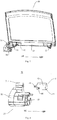
Fig. 7 is a schematic view of a worktable with a driving motor of a washing machine according to an embodiment of the present invention. - Reference will be made in detail to embodiments of the present invention. The same or similar elements and the elements having same or similar functions are denoted by like reference numerals throughout the descriptions. The embodiments described herein with reference to drawings are explanatory, illustrative, and used to generally understand the present invention. The embodiments shall not be construed to limit the present invention.
- In the specification, unless specified or limited otherwise, relative terms such as "central", "longitudinal", "lateral", "front", "rear", "right", "left", "inner", "outer", "lower", "upper", "horizontal", "vertical", "above", "below", "up", "top", "bottom" ,"inner", "outer", "clockwise", "anticlockwise" as well as derivative thereof (e.g., "horizontally", "downwardly", "upwardly", etc.) should be construed to refer to the orientation as then described or as shown in the drawings under discussion. These relative terms are for convenience of description and do not require that the present invention be constructed or operated in a particular orientation. In addition, terms such as "first" and "second" are used herein for purposes of description and are not intended to indicate or imply relative importance or significance. Thus, features limited by "first" and "second" are intended to indicate or imply including one or more than one these features. In the description of the present invention, "a plurality of" relates to two or more than two.
- In the description of the present invention, unless specified or limited otherwise, it should be noted that, terms "mounted," "connected" "coupled" and "fastened" may be understood broadly, such as permanent connection or detachable connection, electronic connection or mechanical connection, direct connection or indirect connection via intermediary, inner communication or inter reaction between two elements. These having ordinary skills in the art should understand the specific meanings in the present invention according to specific situations.
- In the description of the present invention, a structure in which a first feature is "on" a second feature may include an embodiment in which the first feature directly contacts the second feature, and may also include an embodiment in which an additional feature is formed between the first feature and the second feature so that the first feature does not directly contact the second feature, unless otherwise specified. Furthermore, a first feature "on," "above," or "above" a second feature may include an embodiment in which the first feature is right "on," "above," or "above" the second feature, and may also include an embodiment in which the first feature is not right "on," "above," or "above" the second feature, or just means that the first feature has a sea level elevation larger than the sea level elevation of the second feature. While first feature "beneath," "below," or "on bottom of" a second feature may include an embodiment in which the first feature is right "beneath," "below," or "on bottom of" the second feature, and may also include an embodiment in which the first feature is not right "beneath," "below," or "on bottom of" the second feature, or just means that the first feature has a sea level elevation smaller than the sea level elevation of the second feature.
- A
washing machine 100 according to embodiments of the present invention will be described below with reference toFig. 1 to Fig. 7 . - The
washing machine 100 according to embodiments of the present invention may include: acabinet 10, acover 20 and adriving assembly 50. As shown inFig. 3 , thecabinet 10 has aworktable 13 which defines aport 11 for putting into and taking out of laundry. Thecover 20 is disposed on a top of thecabinet 10 and has acover frame 21. Thecover frame 21 has a cover frame edge as a pivotable shaft for thecover 20. Thedriving assembly 50 includes adriving motor 30, and is configured to drive thecover 20 to pivot about the cover frame edge. That is, thedriving assembly 50 may drive thecover 20 to rotate around the cover frame edge to open or close theport 11. It should be understood that, by providing thedriving assembly 50, thewashing machine 100 may realize a function of the electric door opening, so as to improve an automation degree of thewashing machine 100, and further improve experiences of users. - As shown in
Fig. 1 and Fig. 2 , thecover 20 can close theport 11. When thewashing machine 100 is working, thecover 20 closes theport 11 to ensure that the washing machine works normally. Alternatively, when thewashing machine 100 is not working, thecover 20 closes theport 11 to prevent foreign objects from entering into the interior of thewashing machine 100 via theport 11, so as to protect thewashing machine 100 to at least some extent. As shown inFig. 3 , thecover 20 can open theport 11, after clothes have been washed by thewashing machine 100, thecover 20 may open theport 11, so as to take out the clothes for drying. - Specifically, as shown in
Fig. 7 , a receiving space for receiving the drivingmotor 30 is formed in at least one corner of theworktable 13, and theworktable 13 has a corner sidewall at the at least one corner, the corner sidewall of theworktable 13 is adjacent to thecover frame 21, and a left side or a right side of the drivingmotor 30 is adapted to abut against the corner sidewall of theworktable 13. Specifically, as shown inFig. 4 , when thedriving motor 30 is mounted at a left side of thecover 20, the left side of the drivingmotor 30 is abutted against the corner sidewall of theworktable 13. When the drivingmotor 30 is mounted at a right side of thecover 20, the right side of the drivingmotor 30 is abutted against the corner sidewall of theworktable 13. That is, the drivingmotor 30 is disposed at theworktable 13 and the drivingmotor 30 is disposed at the corner of theworktable 13, and the drivingmotor 30 is close to the corner sidewall of theworktable 13 abutted on thecover frame 21, such that the drivingmotor 30 may drive thecover 20 to rotate around thecover frame 21. As shown inFig. 7 , the drivingmotor 30 can be disposed at a left-rear corner of theworktable 13, and the right side of the drivingmotor 30 is close to the corner sidewall of theworktable 13. It should be understood that, by disposing the drivingmotor 30 at the corner of theworktable 13, the problem of the arrangement of the drivingmotor 30 can be solved, and it is possible to further make the space arrangement of theworktable 13 appropriate, and to reduce occupied space of the drivingmotor 30 to facilitate the arrangement of other components (e.g., a detergent dispenser). - Therefore, with the
washing machine 100 according to embodiments of the present invention, it is possible to realize a function of the electric door opening and improve an automation degree of thewashing machine 100, and further improve experiences of users. Moreover, by disposing the drivingmotor 30 at the corner of theworktable 13, the problem of the arrangement of the drivingmotor 30 can be solved, and it is possible to further make the space arrangement of theworktable 13 appropriate, and to reduce occupied space of the drivingmotor 30 to facilitate the arrangement of other components (e.g., a detergent dispenser). - In some embodiments of the present invention, as shown in
Fig. 6 , the drivingassembly 50 further includes an one-way bearing 40, thecover frame 21 has abearing mounting portion 22 at an end thereof, the one-way bearing 40 has a first end fixedly mounted within thebearing mounting portion 22 of thecover 20 and a second end opposite to the first end and connected to the drivingmotor 30, the drivingmotor 30 is configured to drive thecover 20 via the one-way bearing 40 to make thecover 20 pivot about the cover frame edge. - It should be understood that when the driving
motor 30 is working, it may drive the one-way bearing 40 to move. Because the one-way bearing 40 is fixed on thebearing mounting portion 22, thecover 20 and the one-way bearing 40 move synchronously, that is, the drivingmotor 30 may make thecover 20 open theport 11 by driving the one-way bearing 40. As shown inFig. 3 to Fig. 5 , thebearing mounting portion 22 is disposed at thecover frame 21 at the rear end of thecover 20, so as to rotate thecover 20 around thecover frame 21 as the pivotal axis. By providing the drivingmotor 30 and the one-way bearing 40, thecover 20 is easy to rotate, which further simplifies the structure of thewashing machine 100. Alternatively, the drivingmotor 30 may be a reduction motor. It should be understood that, the reduction motor may reduce the output rotation rate to keep the opening rate of thecover 20 driven by the drivingmotor 30 to be moderate. - Specifically, when the
cover 20 needs to close theport 11, the drivingmotor 30 may drive thecover 20 to rotate around thecover frame 21 via the one-way bearing 40 to close theport 11. It should be understood that, at this time, a rotation direction of the drivingmotor 30 is opposite to a rotation direction of the drivingmotor 30 opening thecover 20. Moreover, the rotation rate of the drivingmotor 30 may be lower to prevent the problem of clamping hand of the user by thecover 20 caused by the fact that the rate of thecover 20 when closing theport 11 is too fast, thus improving use safety of thewashing machine 100. - In some embodiments, the
cabinet 10 of thewashing machine 100 may be provided with a control button for opening or closing thecover 20. The control button is connected with the drivingmotor 30, and the user only needs to press the control button to realize the motion of opening or closing thecover 20, thus further improving an automation degree of thewashing machine 100 and experiences of users. - In addition, it should be understood that the
washing machine 100 may further complete the process of closing theport 11 by thecover 20 by manpower. For example, when thecover 20 needs to close theport 11, the drivingmotor 30 stops to work and human hand may press thecover 20 downwardly to close theport 11. - Alternatively, as shown in
Fig. 6 , the one-way bearing 40 includes aninner shaft portion 41 connected to the drivingmotor 30 and anouter ring portion 42 fixedly mounted within thebearing mounting portion 22 of thecover 20. When the drivingmotor 30 drives the one-way bearing 40 to open thecover 20, theinner shaft portion 41 and theouter ring portion 42 move in the same direction, so that theouter ring portion 42 may drive thecover 20 to rotate around thecover frame 21, so as to enable thecover 20 to open theport 11. When the drivingmotor 30 drives the one-way bearing 40 to close thecover 20, the drivingmotor 30 drives theinner shaft portion 41 to rotate, and thecover 20 associated with theouter ring portion 42 moves downwardly under the effect of its own gravity to close theport 11. The difference between the technical effect achieved using the one-way bearing in the electric door of the present invention and the technical effect achieved without using the one-way bearing in the related art will be described in detail as follows. - In the related art, when the cover is only driven by the driving motor without any one-way bearing, if the driving motor is driven to rotate to a first direction, the cover rotates to the first direction and the first direction is set to be a direction of opening the cover; if the driving motor is driven to rotate to a second direction, the cover rotates to the second direction and the second direction is set to be a direction of closing the cover.
- However, when the driving
motor 30 according to embodiments of the present invention drives thecover 20 via the one-way bearing 40, if the drivingmotor 30 is driven to rotate to a first direction, thecover 20 rotates to the first direction and the first direction is set to be a direction of opening the cover; if the drivingmotor 30 is driven to rotate to a second direction, the one-way bearing 40 and theinner shaft portion 41 connected to the drivingmotor 30 rotate to the second direction, the one-way bearing 40 and theouter ring portion 42 connected to thecover 20 will not rotate if thecover 20 is not mounted. However, thecover 20 is mounted to theouter ring portion 42, under the gravity of thecover 20, theouter ring portion 42 following theinner shaft portion 41 rotates to the second direction, so that thecover 20 connected to theouter ring portion 42 falls down or becomes closed under the gravity of thecover 20. If there is an obstacle such as human hand or foreign object during the process of closing thecover 20, despite theinner shaft portion 41 of the one-way bearing 40 rotates under the drive of the drivingmotor 30, theouter ring portion 42 may stop rotating because of the effect of the one-way bearing 40, and thus thecover 20 connected to theouter ring portion 42 may stop falling or be stopped, which prevents the problem of clamping hand of the user by thecover 20, thus improving use safety of thewashing machine 100. When thecover 20 is no more obstructed by the hand and foreign object, it will continue to fall down under the gravity effect to complete the motion of closing the cover. Therefore, the use of the one-way bearing 40 on the drivingmotor 30 can prevent the problem of clamping hands. - Obviously, during the process of closing the
cover 20, if human hand presses further, thecover 20 will be closed faster under pressure. - It should be understood that, the one-
way bearing 40 and the drivingmotor 30 are connected to be used, which is used for the electric door of the washing machine for the first time, and solves the problem of clamping hands by the electric door. - Alternatively, because of an open end of the
bearing mounting portion 22, the drivingmotor 30 and theinner shaft portion 41 of the one-way bearing 40 are easily connected. The one-way bearing 40 is entirely received in thebearing mounting portion 22 and theinner shaft portion 41 of the one-way bearing 40 is extended out from an open end of thebearing mounting portion 22. By receiving the entire one-way bearing 40 in thebearing mounting portion 22, it is possible to improve the reliability of mounting the one-way bearing 40 on thecover 20. A part of theinner shaft portion 41 extending out from thebearing mounting portion 22 may be connected to the drivingmotor 30. Alternatively, as shown inFig. 6 , theouter ring portion 42 of the one-way bearing 40 may be provided with apositioning step 43 for locating a position with thebearing mounting portion 22 and an elastic boss 44 for elastically pressing an inner wall surface of thebearing mounting portion 22. By providing thepositioning step 43 and the elastic boss 44, the one-way bearing 40 may be detachably mounted on thebearing mounting portion 22, so as to facilitate the mounting and dismounting of the one-way bearing 40, and to maintain and replace the one-way bearing 40 in the later period. Moreover, by providing the elastic boss 44, the mounting difficulty of mounting the one-way bearing 40 onto thebearing mounting portion 22 may be reduced, and the mounting stability of the one-way bearing 40 at thebearing mounting portion 22 may be improved. Specifically, thepositioning step 43 and the elastic boss 44 can be spaced apart in an axial direction of the outer ring portion 42 (that is, a left-right direction shown inFig. 6 ), in which eachbearing mounting portion 22 is provided with a groove engaged with thepositioning step 43 and another groove engaged with the elastic boss 44. - Alternatively, the driving
motor 30 defines a driving shaft hole (not shown), and at least a part of theinner shaft portion 41 is inserted into the driving shaft hole. The drivingmotor 30 is provided with an upwardly-extendingear 31, and the driving shaft hole is formed in theear 31. For example, theear 31 is extended upwardly in a radial direction of the drivingmotor 30. That is, theinner shaft portion 41 is extended into theear 31 to cooperate with the driving shaft hole, so that the drivingmotor 30 is connected to theinner shaft portion 41. As shown inFig. 4 , theear 31 can be abutted against an end surface of the end of thebearing mounting portion 22. Specifically, theear 31 can be abutted against an end surface of an end of thebearing mounting portion 22 extending out from a part of theinner shaft portion 41, and by attaching theear 31 to the end surface of the end of thebearing mounting portion 22, the drivingmotor 30 may cooperate with the one-way bearing 40 steadily, and the structure may be compact, which may further save space and improve the space utilization efficiency of thewashing machine 100. - Alternatively, the driving
motor 30 may be a reduction motor. Thus, the output rotation rate of the drivingmotor 30 may meet the need of a moderate rate for thewashing machine 100 to open thecover 20. In a preferred embodiment of the present invention, as shown inFig. 6 , the drivingmotor 30 includes amotor portion 33 and areducer portion 32, which are disposed at a same side of the drivingmotor 30, so as to save more space. Alternatively, thereducer portion 32 may include a plurality of engaged reduction gears. Alternatively, as shown inFig. 7 , themotor portion 33 of the drivingmotor 30 is configured to abut against the corner sidewall of theworktable 13, so that the space arrangement of theworktable 13 may be more appropriate and the space utilization efficiency of theworktable 13 may be improved. - Reference throughout this specification to "an embodiment," "some embodiments," "one embodiment", "another example," "an example," "a specific example," or "some examples," means that a particular feature, structure, material, or characteristic described in connection with the embodiment or example is included in at least one embodiment or example of the present invention. Thus, the appearances of the phrases such as "in some embodiments," "in one embodiment", "in an embodiment", "in another example," "in an example," "in a specific example," or "in some examples," in various places throughout this specification are not necessarily referring to the same embodiment or example of the present invention. Furthermore, the particular features, structures, materials, or characteristics may be combined in any suitable manner in one or more embodiments or examples.
- Although explanatory embodiments have been shown and described, it would be appreciated by those skilled in the art that the above embodiments cannot be construed to limit the present invention, and changes, alternatives, and modifications can be made in the embodiments without departing from spirit, principles and scope of the present invention.
Claims (10)
- A washing machine (100), comprising:a cabinet (10) having a worktable (13), said worktable defining a port (11) for putting into and taking out of laundry;a cover (20) disposed on a top of the cabinet (10) and having a cover frame (21), the cover frame (21) having a cover frame edge as a pivotable shaft for the cover (20); anda driving assembly (50) comprising a driving motor (30), the driving assembly (50) being configured to drive the cover (20) to pivot about said cover frame edge;wherein the worktable (13) defines a receiving space in at least one corner thereof for receiving the driving motor (30), the worktable (13) has a corner sidewall at said at least one corner, the corner sidewall of the worktable (13) is adjacent to the cover frame (21), a left side or a right side of the driving motor (30) is adapted to abut against said corner sidewall of the worktable (13).
- The washing machine (100) according to claim 1, wherein the driving assembly (50) further comprises an one-way bearing (40), the cover frame (21) has a bearing mounting portion (22) at an end of the cover frame edge, the one-way bearing (40) defines a first end fixedly mounted with the bearing mounting portion (22) of the cover (20) and a second end opposite to the first end, said second end of the one-way bearing (40) being connected to the driving motor (30), the driving motor (30) is configured to drive the cover (20) via the one-way bearing (40) so as to make the cover (20) pivot about the cover frame edge.
- The washing machine (100) according to claim 2, wherein the one-way bearing (40) comprises an inner shaft portion (41) connected to the driving motor (30) and an outer ring portion (42) fixedly mounted within the bearing mounting portion (22) of the cover (20).
- The washing machine (100) according to claim 3, wherein the one-way bearing (40) is received in the bearing mounting portion (22) and the inner shaft portion (41) of the one-way bearing (40) is configured to extend out from an open end of the bearing mounting portion (22).
- The washing machine (100) according to claim 3 or 4, wherein the driving motor (30) defines a driving shaft hole, at least a part of the inner shaft portion (41) is inserted into the driving shaft hole.
- The washing machine (100) according to claim 5, wherein the driving motor (30) is provided with an upwardly-extending ear (31), the driving shaft hole is formed in the ear (31).
- The washing machine (100) according to claim 6, wherein the ear (31) is configured to abut against an end surface of the end of the bearing mounting portion (22).
- The washing machine (100) according to one of claims 1 to 7, wherein the driving motor (30) is a reduction motor.
- The washing machine (100) according to one of claims 1 to 8, wherein the driving motor (30) comprises a motor portion (33) and a reducer portion (32), which are disposed at a same side of the driving motor (30).
- The washing machine (100) according to one of claims 1 to 9, wherein said motor portion (33) of the driving motor (30) is configured to abut against the corner sidewall of the worktable (13).
Applications Claiming Priority (2)
| Application Number | Priority Date | Filing Date | Title |
|---|---|---|---|
| CN201510470997.1A CN106436168B (en) | 2015-08-04 | 2015-08-04 | Washing machine |
| CN201520578513.0U CN204959400U (en) | 2015-08-04 | 2015-08-04 | Washing machine |
Publications (2)
| Publication Number | Publication Date |
|---|---|
| EP3128068A1 true EP3128068A1 (en) | 2017-02-08 |
| EP3128068B1 EP3128068B1 (en) | 2019-04-10 |
Family
ID=55809034
Family Applications (1)
| Application Number | Title | Priority Date | Filing Date |
|---|---|---|---|
| EP16166991.6A Active EP3128068B1 (en) | 2015-08-04 | 2016-04-26 | Washing machine |
Country Status (1)
| Country | Link |
|---|---|
| EP (1) | EP3128068B1 (en) |
Citations (6)
| Publication number | Priority date | Publication date | Assignee | Title |
|---|---|---|---|---|
| US5724837A (en) * | 1995-11-09 | 1998-03-10 | Samsung Electronics Co., Ltd. | Clothes washer having a motor-driven lid opening and closing mechanism |
| US5870787A (en) * | 1995-11-09 | 1999-02-16 | Samsung Electronics Co., Ltd. | Door driving control apparatus and method for a washing machine |
| US5903120A (en) * | 1995-04-28 | 1999-05-11 | Samsung Electronics Co., Ltd. | Clothes washing machine having a two-piece door pulled open and closed by a motor-driven wire arrangement |
| EP1949843A1 (en) * | 2007-01-29 | 2008-07-30 | International Steel Co. SpA | Safety device for a closing element of a washing, thermal-disinfection, sterilization, preservation, refrigeration, heating machine, or suchlike |
| WO2015123933A1 (en) * | 2014-02-24 | 2015-08-27 | 海尔集团公司 | Opening/closing mechanism for washing machine top cover and washing machine |
| CN204959362U (en) | 2015-05-29 | 2016-01-13 | 无锡小天鹅股份有限公司 | Washing machine |
-
2016
- 2016-04-26 EP EP16166991.6A patent/EP3128068B1/en active Active
Patent Citations (6)
| Publication number | Priority date | Publication date | Assignee | Title |
|---|---|---|---|---|
| US5903120A (en) * | 1995-04-28 | 1999-05-11 | Samsung Electronics Co., Ltd. | Clothes washing machine having a two-piece door pulled open and closed by a motor-driven wire arrangement |
| US5724837A (en) * | 1995-11-09 | 1998-03-10 | Samsung Electronics Co., Ltd. | Clothes washer having a motor-driven lid opening and closing mechanism |
| US5870787A (en) * | 1995-11-09 | 1999-02-16 | Samsung Electronics Co., Ltd. | Door driving control apparatus and method for a washing machine |
| EP1949843A1 (en) * | 2007-01-29 | 2008-07-30 | International Steel Co. SpA | Safety device for a closing element of a washing, thermal-disinfection, sterilization, preservation, refrigeration, heating machine, or suchlike |
| WO2015123933A1 (en) * | 2014-02-24 | 2015-08-27 | 海尔集团公司 | Opening/closing mechanism for washing machine top cover and washing machine |
| CN204959362U (en) | 2015-05-29 | 2016-01-13 | 无锡小天鹅股份有限公司 | Washing machine |
Also Published As
| Publication number | Publication date |
|---|---|
| EP3128068B1 (en) | 2019-04-10 |
Similar Documents
| Publication | Publication Date | Title |
|---|---|---|
| KR101604688B1 (en) | Laundry machine | |
| CN204959402U (en) | Washing machine | |
| KR20130123544A (en) | Door apparatus for drum washing machine | |
| CN204959401U (en) | Washing machine | |
| EP3128066A1 (en) | Washing machine | |
| CN107385764B (en) | Drum washing machine with movable clothes taking and placing opening | |
| JP2014018611A (en) | Washing machine | |
| KR20030062484A (en) | A door's installing structure of the drum type washer | |
| EP3128068B1 (en) | Washing machine | |
| KR100600764B1 (en) | Drum Washing Machine with Bottom Open Door | |
| EP3128062B1 (en) | Washing machine | |
| CN210961650U (en) | Low-noise food processor | |
| EP3128067A1 (en) | Washing machine | |
| CN116602542B (en) | Top cover and cooking utensils with it | |
| EP3848497A1 (en) | Laundry treatment apparatus | |
| CN107012642B (en) | Movable drum washing machine with clothes taking and putting opening | |
| CN215104100U (en) | washing machine | |
| CN215561348U (en) | Clothes treatment device | |
| EP3130700A1 (en) | Driving motor assembly for electric door of washing machine | |
| CN205012049U (en) | Washing machine | |
| CN209284791U (en) | It is a kind of can automatic accomodation bath mirror | |
| CN209761166U (en) | Intelligence sliding window with remote control function | |
| CN209323182U (en) | Drum washing machine | |
| CN209770167U (en) | Automatic tool rest is hidden to formula and basin that has automatic formula and hide tool rest | |
| CN215686955U (en) | Cooking utensil |
Legal Events
| Date | Code | Title | Description |
|---|---|---|---|
| PUAI | Public reference made under article 153(3) epc to a published international application that has entered the european phase |
Free format text: ORIGINAL CODE: 0009012 |
|
| STAA | Information on the status of an ep patent application or granted ep patent |
Free format text: STATUS: REQUEST FOR EXAMINATION WAS MADE |
|
| 17P | Request for examination filed |
Effective date: 20160517 |
|
| AK | Designated contracting states |
Kind code of ref document: A1 Designated state(s): AL AT BE BG CH CY CZ DE DK EE ES FI FR GB GR HR HU IE IS IT LI LT LU LV MC MK MT NL NO PL PT RO RS SE SI SK SM TR |
|
| AX | Request for extension of the european patent |
Extension state: BA ME |
|
| R17P | Request for examination filed (corrected) |
Effective date: 20160517 |
|
| RBV | Designated contracting states (corrected) |
Designated state(s): AL AT BE BG CH CY CZ DE DK EE ES FI FR GB GR HR HU IE IS IT LI LT LU LV MC MK MT NL NO PL PT RO RS SE SI SK SM TR |
|
| RIC1 | Information provided on ipc code assigned before grant |
Ipc: D06F 23/04 20060101ALN20180822BHEP Ipc: D06F 39/14 20060101AFI20180822BHEP |
|
| GRAP | Despatch of communication of intention to grant a patent |
Free format text: ORIGINAL CODE: EPIDOSNIGR1 |
|
| STAA | Information on the status of an ep patent application or granted ep patent |
Free format text: STATUS: GRANT OF PATENT IS INTENDED |
|
| INTG | Intention to grant announced |
Effective date: 20181018 |
|
| RAP1 | Party data changed (applicant data changed or rights of an application transferred) |
Owner name: WUXI LITTLE SWAN CO., LTD. |
|
| GRAS | Grant fee paid |
Free format text: ORIGINAL CODE: EPIDOSNIGR3 |
|
| GRAA | (expected) grant |
Free format text: ORIGINAL CODE: 0009210 |
|
| STAA | Information on the status of an ep patent application or granted ep patent |
Free format text: STATUS: THE PATENT HAS BEEN GRANTED |
|
| AK | Designated contracting states |
Kind code of ref document: B1 Designated state(s): AL AT BE BG CH CY CZ DE DK EE ES FI FR GB GR HR HU IE IS IT LI LT LU LV MC MK MT NL NO PL PT RO RS SE SI SK SM TR |
|
| REG | Reference to a national code |
Ref country code: GB Ref legal event code: FG4D |
|
| REG | Reference to a national code |
Ref country code: CH Ref legal event code: EP Ref country code: AT Ref legal event code: REF Ref document number: 1118779 Country of ref document: AT Kind code of ref document: T Effective date: 20190415 |
|
| REG | Reference to a national code |
Ref country code: IE Ref legal event code: FG4D |
|
| REG | Reference to a national code |
Ref country code: DE Ref legal event code: R096 Ref document number: 602016012091 Country of ref document: DE |
|
| REG | Reference to a national code |
Ref country code: NL Ref legal event code: MP Effective date: 20190410 |
|
| REG | Reference to a national code |
Ref country code: LT Ref legal event code: MG4D |
|
| REG | Reference to a national code |
Ref country code: AT Ref legal event code: MK05 Ref document number: 1118779 Country of ref document: AT Kind code of ref document: T Effective date: 20190410 |
|
| PG25 | Lapsed in a contracting state [announced via postgrant information from national office to epo] |
Ref country code: NL Free format text: LAPSE BECAUSE OF FAILURE TO SUBMIT A TRANSLATION OF THE DESCRIPTION OR TO PAY THE FEE WITHIN THE PRESCRIBED TIME-LIMIT Effective date: 20190410 |
|
| PG25 | Lapsed in a contracting state [announced via postgrant information from national office to epo] |
Ref country code: HR Free format text: LAPSE BECAUSE OF FAILURE TO SUBMIT A TRANSLATION OF THE DESCRIPTION OR TO PAY THE FEE WITHIN THE PRESCRIBED TIME-LIMIT Effective date: 20190410 Ref country code: PT Free format text: LAPSE BECAUSE OF FAILURE TO SUBMIT A TRANSLATION OF THE DESCRIPTION OR TO PAY THE FEE WITHIN THE PRESCRIBED TIME-LIMIT Effective date: 20190910 Ref country code: LT Free format text: LAPSE BECAUSE OF FAILURE TO SUBMIT A TRANSLATION OF THE DESCRIPTION OR TO PAY THE FEE WITHIN THE PRESCRIBED TIME-LIMIT Effective date: 20190410 Ref country code: SE Free format text: LAPSE BECAUSE OF FAILURE TO SUBMIT A TRANSLATION OF THE DESCRIPTION OR TO PAY THE FEE WITHIN THE PRESCRIBED TIME-LIMIT Effective date: 20190410 Ref country code: NO Free format text: LAPSE BECAUSE OF FAILURE TO SUBMIT A TRANSLATION OF THE DESCRIPTION OR TO PAY THE FEE WITHIN THE PRESCRIBED TIME-LIMIT Effective date: 20190710 Ref country code: ES Free format text: LAPSE BECAUSE OF FAILURE TO SUBMIT A TRANSLATION OF THE DESCRIPTION OR TO PAY THE FEE WITHIN THE PRESCRIBED TIME-LIMIT Effective date: 20190410 Ref country code: AL Free format text: LAPSE BECAUSE OF FAILURE TO SUBMIT A TRANSLATION OF THE DESCRIPTION OR TO PAY THE FEE WITHIN THE PRESCRIBED TIME-LIMIT Effective date: 20190410 Ref country code: FI Free format text: LAPSE BECAUSE OF FAILURE TO SUBMIT A TRANSLATION OF THE DESCRIPTION OR TO PAY THE FEE WITHIN THE PRESCRIBED TIME-LIMIT Effective date: 20190410 |
|
| PG25 | Lapsed in a contracting state [announced via postgrant information from national office to epo] |
Ref country code: BG Free format text: LAPSE BECAUSE OF FAILURE TO SUBMIT A TRANSLATION OF THE DESCRIPTION OR TO PAY THE FEE WITHIN THE PRESCRIBED TIME-LIMIT Effective date: 20190710 Ref country code: GR Free format text: LAPSE BECAUSE OF FAILURE TO SUBMIT A TRANSLATION OF THE DESCRIPTION OR TO PAY THE FEE WITHIN THE PRESCRIBED TIME-LIMIT Effective date: 20190711 Ref country code: RS Free format text: LAPSE BECAUSE OF FAILURE TO SUBMIT A TRANSLATION OF THE DESCRIPTION OR TO PAY THE FEE WITHIN THE PRESCRIBED TIME-LIMIT Effective date: 20190410 Ref country code: LV Free format text: LAPSE BECAUSE OF FAILURE TO SUBMIT A TRANSLATION OF THE DESCRIPTION OR TO PAY THE FEE WITHIN THE PRESCRIBED TIME-LIMIT Effective date: 20190410 Ref country code: PL Free format text: LAPSE BECAUSE OF FAILURE TO SUBMIT A TRANSLATION OF THE DESCRIPTION OR TO PAY THE FEE WITHIN THE PRESCRIBED TIME-LIMIT Effective date: 20190410 |
|
| REG | Reference to a national code |
Ref country code: CH Ref legal event code: PL |
|
| RAP2 | Party data changed (patent owner data changed or rights of a patent transferred) |
Owner name: WUXI LITTLE SWAN ELECTRIC CO., LTD. |
|
| REG | Reference to a national code |
Ref country code: BE Ref legal event code: MM Effective date: 20190430 |
|
| PG25 | Lapsed in a contracting state [announced via postgrant information from national office to epo] |
Ref country code: LU Free format text: LAPSE BECAUSE OF NON-PAYMENT OF DUE FEES Effective date: 20190426 Ref country code: IS Free format text: LAPSE BECAUSE OF FAILURE TO SUBMIT A TRANSLATION OF THE DESCRIPTION OR TO PAY THE FEE WITHIN THE PRESCRIBED TIME-LIMIT Effective date: 20190810 Ref country code: AT Free format text: LAPSE BECAUSE OF FAILURE TO SUBMIT A TRANSLATION OF THE DESCRIPTION OR TO PAY THE FEE WITHIN THE PRESCRIBED TIME-LIMIT Effective date: 20190410 |
|
| REG | Reference to a national code |
Ref country code: DE Ref legal event code: R097 Ref document number: 602016012091 Country of ref document: DE |
|
| REG | Reference to a national code |
Ref country code: DE Ref legal event code: R082 Ref document number: 602016012091 Country of ref document: DE Representative=s name: MAUCHER JENKINS PATENTANWAELTE & RECHTSANWAELT, DE Ref country code: DE Ref legal event code: R081 Ref document number: 602016012091 Country of ref document: DE Owner name: WUXI LITTLE SWAN ELECTRIC CO., LTD., WUXI, CN Free format text: FORMER OWNER: WUXI LITTLE SWAN CO., LTD., WUXI, JIANGSU, CN |
|
| PG25 | Lapsed in a contracting state [announced via postgrant information from national office to epo] |
Ref country code: LI Free format text: LAPSE BECAUSE OF NON-PAYMENT OF DUE FEES Effective date: 20190430 Ref country code: EE Free format text: LAPSE BECAUSE OF FAILURE TO SUBMIT A TRANSLATION OF THE DESCRIPTION OR TO PAY THE FEE WITHIN THE PRESCRIBED TIME-LIMIT Effective date: 20190410 Ref country code: DK Free format text: LAPSE BECAUSE OF FAILURE TO SUBMIT A TRANSLATION OF THE DESCRIPTION OR TO PAY THE FEE WITHIN THE PRESCRIBED TIME-LIMIT Effective date: 20190410 Ref country code: CH Free format text: LAPSE BECAUSE OF NON-PAYMENT OF DUE FEES Effective date: 20190430 Ref country code: MC Free format text: LAPSE BECAUSE OF FAILURE TO SUBMIT A TRANSLATION OF THE DESCRIPTION OR TO PAY THE FEE WITHIN THE PRESCRIBED TIME-LIMIT Effective date: 20190410 Ref country code: SK Free format text: LAPSE BECAUSE OF FAILURE TO SUBMIT A TRANSLATION OF THE DESCRIPTION OR TO PAY THE FEE WITHIN THE PRESCRIBED TIME-LIMIT Effective date: 20190410 Ref country code: RO Free format text: LAPSE BECAUSE OF FAILURE TO SUBMIT A TRANSLATION OF THE DESCRIPTION OR TO PAY THE FEE WITHIN THE PRESCRIBED TIME-LIMIT Effective date: 20190410 Ref country code: CZ Free format text: LAPSE BECAUSE OF FAILURE TO SUBMIT A TRANSLATION OF THE DESCRIPTION OR TO PAY THE FEE WITHIN THE PRESCRIBED TIME-LIMIT Effective date: 20190410 |
|
| PLBE | No opposition filed within time limit |
Free format text: ORIGINAL CODE: 0009261 |
|
| STAA | Information on the status of an ep patent application or granted ep patent |
Free format text: STATUS: NO OPPOSITION FILED WITHIN TIME LIMIT |
|
| PG25 | Lapsed in a contracting state [announced via postgrant information from national office to epo] |
Ref country code: BE Free format text: LAPSE BECAUSE OF NON-PAYMENT OF DUE FEES Effective date: 20190430 Ref country code: SM Free format text: LAPSE BECAUSE OF FAILURE TO SUBMIT A TRANSLATION OF THE DESCRIPTION OR TO PAY THE FEE WITHIN THE PRESCRIBED TIME-LIMIT Effective date: 20190410 Ref country code: IT Free format text: LAPSE BECAUSE OF FAILURE TO SUBMIT A TRANSLATION OF THE DESCRIPTION OR TO PAY THE FEE WITHIN THE PRESCRIBED TIME-LIMIT Effective date: 20190410 |
|
| 26N | No opposition filed |
Effective date: 20200113 |
|
| PG25 | Lapsed in a contracting state [announced via postgrant information from national office to epo] |
Ref country code: TR Free format text: LAPSE BECAUSE OF FAILURE TO SUBMIT A TRANSLATION OF THE DESCRIPTION OR TO PAY THE FEE WITHIN THE PRESCRIBED TIME-LIMIT Effective date: 20190410 |
|
| PG25 | Lapsed in a contracting state [announced via postgrant information from national office to epo] |
Ref country code: IE Free format text: LAPSE BECAUSE OF NON-PAYMENT OF DUE FEES Effective date: 20190426 |
|
| PG25 | Lapsed in a contracting state [announced via postgrant information from national office to epo] |
Ref country code: SI Free format text: LAPSE BECAUSE OF FAILURE TO SUBMIT A TRANSLATION OF THE DESCRIPTION OR TO PAY THE FEE WITHIN THE PRESCRIBED TIME-LIMIT Effective date: 20190410 |
|
| PG25 | Lapsed in a contracting state [announced via postgrant information from national office to epo] |
Ref country code: FR Free format text: LAPSE BECAUSE OF NON-PAYMENT OF DUE FEES Effective date: 20190610 |
|
| GBPC | Gb: european patent ceased through non-payment of renewal fee |
Effective date: 20200426 |
|
| PG25 | Lapsed in a contracting state [announced via postgrant information from national office to epo] |
Ref country code: GB Free format text: LAPSE BECAUSE OF NON-PAYMENT OF DUE FEES Effective date: 20200426 |
|
| PG25 | Lapsed in a contracting state [announced via postgrant information from national office to epo] |
Ref country code: CY Free format text: LAPSE BECAUSE OF FAILURE TO SUBMIT A TRANSLATION OF THE DESCRIPTION OR TO PAY THE FEE WITHIN THE PRESCRIBED TIME-LIMIT Effective date: 20190410 |
|
| PG25 | Lapsed in a contracting state [announced via postgrant information from national office to epo] |
Ref country code: MT Free format text: LAPSE BECAUSE OF FAILURE TO SUBMIT A TRANSLATION OF THE DESCRIPTION OR TO PAY THE FEE WITHIN THE PRESCRIBED TIME-LIMIT Effective date: 20190410 Ref country code: HU Free format text: LAPSE BECAUSE OF FAILURE TO SUBMIT A TRANSLATION OF THE DESCRIPTION OR TO PAY THE FEE WITHIN THE PRESCRIBED TIME-LIMIT; INVALID AB INITIO Effective date: 20160426 |
|
| PG25 | Lapsed in a contracting state [announced via postgrant information from national office to epo] |
Ref country code: MK Free format text: LAPSE BECAUSE OF FAILURE TO SUBMIT A TRANSLATION OF THE DESCRIPTION OR TO PAY THE FEE WITHIN THE PRESCRIBED TIME-LIMIT Effective date: 20190410 |
|
| PGFP | Annual fee paid to national office [announced via postgrant information from national office to epo] |
Ref country code: DE Payment date: 20250417 Year of fee payment: 10 |