EP3127846A1 - Telephone wire withdrawing device - Google Patents
Telephone wire withdrawing device Download PDFInfo
- Publication number
- EP3127846A1 EP3127846A1 EP14888547.8A EP14888547A EP3127846A1 EP 3127846 A1 EP3127846 A1 EP 3127846A1 EP 14888547 A EP14888547 A EP 14888547A EP 3127846 A1 EP3127846 A1 EP 3127846A1
- Authority
- EP
- European Patent Office
- Prior art keywords
- telephone wire
- slider
- frame
- toothed component
- roller
- Prior art date
- Legal status (The legal status is an assumption and is not a legal conclusion. Google has not performed a legal analysis and makes no representation as to the accuracy of the status listed.)
- Granted
Links
- 230000007246 mechanism Effects 0.000 claims abstract description 40
- 230000006870 function Effects 0.000 abstract description 20
- 230000009471 action Effects 0.000 description 10
- 238000000034 method Methods 0.000 description 9
- 230000008569 process Effects 0.000 description 6
- 238000004891 communication Methods 0.000 description 5
- 230000008901 benefit Effects 0.000 description 4
- 230000008878 coupling Effects 0.000 description 3
- 238000010168 coupling process Methods 0.000 description 3
- 238000005859 coupling reaction Methods 0.000 description 3
- 238000012986 modification Methods 0.000 description 2
- 230000004048 modification Effects 0.000 description 2
- 238000006467 substitution reaction Methods 0.000 description 2
- 238000013461 design Methods 0.000 description 1
- 238000011161 development Methods 0.000 description 1
- 238000005516 engineering process Methods 0.000 description 1
- 238000012423 maintenance Methods 0.000 description 1
- 230000003287 optical effect Effects 0.000 description 1
- 238000012545 processing Methods 0.000 description 1
Images



Classifications
-
- B—PERFORMING OPERATIONS; TRANSPORTING
- B65—CONVEYING; PACKING; STORING; HANDLING THIN OR FILAMENTARY MATERIAL
- B65H—HANDLING THIN OR FILAMENTARY MATERIAL, e.g. SHEETS, WEBS, CABLES
- B65H75/00—Storing webs, tapes, or filamentary material, e.g. on reels
- B65H75/02—Cores, formers, supports, or holders for coiled, wound, or folded material, e.g. reels, spindles, bobbins, cop tubes, cans, mandrels or chucks
- B65H75/34—Cores, formers, supports, or holders for coiled, wound, or folded material, e.g. reels, spindles, bobbins, cop tubes, cans, mandrels or chucks specially adapted or mounted for storing and repeatedly paying-out and re-storing lengths of material provided for particular purposes, e.g. anchored hoses, power cables
- B65H75/38—Cores, formers, supports, or holders for coiled, wound, or folded material, e.g. reels, spindles, bobbins, cop tubes, cans, mandrels or chucks specially adapted or mounted for storing and repeatedly paying-out and re-storing lengths of material provided for particular purposes, e.g. anchored hoses, power cables involving the use of a core or former internal to, and supporting, a stored package of material
- B65H75/44—Constructional details
- B65H75/4418—Arrangements for stopping winding or unwinding; Arrangements for releasing the stop means
-
- B—PERFORMING OPERATIONS; TRANSPORTING
- B65—CONVEYING; PACKING; STORING; HANDLING THIN OR FILAMENTARY MATERIAL
- B65H—HANDLING THIN OR FILAMENTARY MATERIAL, e.g. SHEETS, WEBS, CABLES
- B65H75/00—Storing webs, tapes, or filamentary material, e.g. on reels
- B65H75/02—Cores, formers, supports, or holders for coiled, wound, or folded material, e.g. reels, spindles, bobbins, cop tubes, cans, mandrels or chucks
- B65H75/34—Cores, formers, supports, or holders for coiled, wound, or folded material, e.g. reels, spindles, bobbins, cop tubes, cans, mandrels or chucks specially adapted or mounted for storing and repeatedly paying-out and re-storing lengths of material provided for particular purposes, e.g. anchored hoses, power cables
- B65H75/36—Cores, formers, supports, or holders for coiled, wound, or folded material, e.g. reels, spindles, bobbins, cop tubes, cans, mandrels or chucks specially adapted or mounted for storing and repeatedly paying-out and re-storing lengths of material provided for particular purposes, e.g. anchored hoses, power cables without essentially involving the use of a core or former internal to a stored package of material, e.g. with stored material housed within casing or container, or intermittently engaging a plurality of supports as in sinuous or serpentine fashion
- B65H75/368—Cores, formers, supports, or holders for coiled, wound, or folded material, e.g. reels, spindles, bobbins, cop tubes, cans, mandrels or chucks specially adapted or mounted for storing and repeatedly paying-out and re-storing lengths of material provided for particular purposes, e.g. anchored hoses, power cables without essentially involving the use of a core or former internal to a stored package of material, e.g. with stored material housed within casing or container, or intermittently engaging a plurality of supports as in sinuous or serpentine fashion with pulleys
-
- B—PERFORMING OPERATIONS; TRANSPORTING
- B65—CONVEYING; PACKING; STORING; HANDLING THIN OR FILAMENTARY MATERIAL
- B65H—HANDLING THIN OR FILAMENTARY MATERIAL, e.g. SHEETS, WEBS, CABLES
- B65H2701/00—Handled material; Storage means
- B65H2701/30—Handled filamentary material
- B65H2701/34—Handled filamentary material electric cords or electric power cables
Definitions
- the present application relates to the field of communication devices, and particularly to a telephone wire withdrawing device.
- a telephone wire is connected to a handset of a wired telephone, and a user can move within a range limited by the length of the telephone wire while holding the telephone receiver.
- the telephone wire may bring some obstacles and troubles to the user. Therefore, there is a rotary telephone wire withdrawing device, and the exposed length of the telephone wire may be reduced by pulling and withdrawing the telephone wire, thus reducing the inconvenience caused by the telephone wire to the user to some extent.
- a telephone wire withdrawing device is provided according to the present application, which is capable of achieving pulling and withdrawing functions of a telephone wire to smooth the operation and improve the user experience, and furthermore, since it is unnecessary to use an electric brush, the call distortion caused by using the electric brush is avoided.
- a telephone wire withdrawing device is provided according to the present application, which includes:
- the toothed component 10 is provided with teeth on a rim thereof, and the toothed component 10 meshes with the rack-like groove 15.
- the swing piece 11 has a central shaft fixed on the toothed component 10, and the swing piece 11 rotates on the toothed component 10 about the central shaft.
- the swing piece 11 is provided with a position-limiting protrusion 17.
- the resilient sheet B13 is provided with a position-limiting bump 18.
- the slider 1 cooperatively slides upwards or downwards in the guiding slot 14.
- the base 9 is provided with two L-shaped lug bosses 16, the two L-shaped lug bosses 16 are symmetrical about a central axis of the base 9.
- a telephone wire withdrawing device includes a slider 1, a frame 2, a handset 3, a telephone wire 4, a roller A5, a rotary self-locking mechanism 6, a roller B7 and an extension spring 8.
- the rotary self-locking mechanism includes the base 9, the toothed component 10, the swing piece 11, the resilient sheet A12 and a resilient sheet B13.
- the slider 1 is fitted in the guiding slot 14 of the frame 2, and slides cooperatively in the guiding slot 14.
- the roller A5 is fixed on the slider 1.
- the telephone wire 4 has one end fixed on the frame 2, and another end rounding the roller A5 and connected to the handset 3.
- the roller B7 is fixed on the frame 2.
- the extension spring 8 has one end fixed on the frame 2 and another end rounding the roller B7 and connected to the slider 1 to provide a restoring force for the slider 1 when the slider 1 slides cooperatively in the guiding slot 14.
- the frame 2 is provided with a rack-like groove 15, and the rack-like groove 15 and the toothed component 10 of the rotary self-locking mechanism 6 constitute a gear-rack-like structure.
- the base 9 of the rotary self-locking mechanism 6 is fixed on the slider 1, and when the slider 1 slides cooperatively in the guiding slot 14, the toothed component 10 of the rotary self-locking mechanism 6 meshes with the rack-like groove 15 of the frame 2 and rolls in the rack-like groove 15 of the frame 2 to achieve a relative rotation between the base 9 and the toothed component 10 of the rotary self-locking mechanism 6.
- the swing piece 11, the resilient sheet A12 and the resilient sheet B13 are fixed on the toothed component 10.
- the base 9 is provided with at least one L-shaped lug boss 16.
- the telephone wire 4 connected in the handset 3 may slide in the guiding slot 14 of the frame 2 via the roller A5 and the slider 1 to achieve the pulling function of the telephone wire, and with a restoring force for the slider 1 provided by the extension spring 8, the withdrawing function of the telephone wire can be achieved. Furthermore, since when the slider 1 slides cooperatively in the guiding slot 14, the toothed component 10 meshes with the rack-like groove 15 of the frame 2 and rolls in the rack-like groove 15 of the frame 2, the pulling and withdrawing operations of the telephone wire 4 are smooth, and the user experience is improved. In addition, since it is unnecessary to use an electric brush, the call distortion caused by using the electric brush is avoided.
- a telephone wire withdrawing device is provided according to an embodiment of the present application, to achieve pulling and withdrawing functions of a telephone wire so as to obtain a smooth operation and improve the user experience, and further to avoid the call distortion caused by an electric brush due to the fact that the electric brush is not necessarily used by the telephone wire withdrawing device.
- an embodiment of a telephone wire withdrawing device includes: a slider 1, a frame 2, a handset 3, a telephone wire 4, a roller A5, a rotary self-locking mechanism 6, a roller B7, and an extension spring 8.
- the rotary self-locking mechanism includes a base 9, a toothed component 10, a swing piece 11, a resilient sheet A 12 and a resilient sheet B13.
- the slider 1 is fitted in a guiding slot 14 of the frame 2, and can slide cooperatively in the guiding slot 14.
- the roller A5 is fixed on the slider 1.
- the telephone wire 4 has one end fixed on the frame 2, and another end rounding the roller A5 and connected to the handset 3. It should be noted that, as shown in Figure 2 , the telephone wire 4 may have one end fixed on a position Z on the frame 2, and another end rounding the roller A5 and being connected to the handset 3.
- the roller B7 is fixed on the frame 2.
- the extension spring 8 has one end fixed on the frame 2 and another end rounding the roller B7 and being connected to the slider 1, which is configured to provide a restoring force for the slider 1 in the case that the slider 1 slides cooperatively in the guiding slot 14. It should be noted that, as shown in Figure 2 , the extension spring 8 has one end fixed at a position Y on the frame 2 and another end rounding the roller B7 and being connected at the position X on the slider 1.
- the frame 2 is provided with a rack-like groove 15, and the rack-like groove 15 and the toothed component 10 of the rotary self-locking mechanism 6 constitute a gear-rack-like structure.
- the base 9 of the rotary self-locking mechanism 6 is fixed on the slider 1, and in the case that the slider 1 slides cooperatively in the guiding slot 14, the toothed component 10 of the rotary self-locking mechanism 6 meshes and rolls in the rack-like groove 15 of the frame 2 to achieve a relative rotation between the base 9 and the toothed component 10 of the rotary self-locking mechanism 6.
- the swing piece 11, the resilient sheet A12 and the resilient sheet B13 are fixed on the toothed component 10.
- the toothed component 10 is provided with teeth on a rim thereof and the teeth mesh with the rack-like groove 15;
- the swing piece 11 has a central shaft fixed on the toothed component 10, and the swing piece 11 rotates on the toothed component 10 about the central shaft.
- the swing piece 11 is provided with a position-limiting protrusion 17.
- the resilient sheet B13 is provided with a position-limiting bump 18.
- the slider 1 cooperatively slides upwards or downwards in the guiding slot 14.
- the base 9 is provided with two L-shaped lug bosses 16, and the two L-shaped lug bosses 16 are symmetrical about a central axis of the base 9.
- the user may slightly pull the telephone wire 4 upwardly to straighten the telephone wire 4 and bring the slider 1 to move upwardly by a short distance. Then, the toothed component 10 may drive the swing piece 11 to rotate counterclockwise under the action of the gear-rack-like structure.
- the position-limiting bump 18 of the resilient sheet B13 is pressed on the position-limiting protrusion 17 of the swing piece 11 to provide a force for rotating the swing piece 11 counterclockwise, and the swing piece 11 may rotate counterclockwise by a certain degree under the force provided by the resilient sheet B13 and then rotates to a state shown in Figure 13 .
- the slider 1 may drive the telephone wire 4 to move downwardly under the action of the extension spring 8, and the toothed component 10 may drive the swing piece 11 to rotate clockwise under the action of the gear-rack-like structure.
- the L-shaped lug boss 16 of the base 2, and the swing piece 11 may not limit the downward movement of the slider 1, thus achieving the automatic withdrawing function of the telephone wire.
- a telephone wire withdrawing device includes a slider 1, a frame 2, a handset 3, a telephone wire 4, a roller A5, a rotary self-locking mechanism 6, a roller B7 and an extension spring 8.
- the rotary self-locking mechanism includes a base 9, a toothed component 10, a swing piece 11, a resilient sheet A12, and a resilient sheet B13.
- the slider 1 is fitted in the guiding slot 14 of the frame 2, and slides cooperatively in the guiding slot 14.
- the roller A5 is fixed on the slider 1.
- the telephone wire 4 has one end fixed on the frame 2, and another end rounding the roller A5 and connected in the handset 3.
- the roller B7 is fixed on the frame 2.
- the extension spring 8 has one end fixed on the frame 2, and has another end rounding the roller B7 and connected on the slider 1 to provide a restoring force for the slider 1 in the case that the slider 1 slides cooperatively in the guiding slot 14.
- the frame 2 is provided with a rack-like groove 15, and the rack-like groove 15 and the toothed component 10 of the rotary self-locking mechanism 6 constitute a gear-rack-like structure.
- the base 9 of the rotary self-locking mechanism 6 is fixed on the slider 1, and in the case that the slider 1 slides cooperatively in the guiding slot 14, the toothed component 10 of the rotary self-locking mechanism 6 meshes and rolls in the rack-like groove 15 of the frame 2 to realize a relative rotation between the base 9 and the toothed component 10 of the rotary self-locking mechanism 6.
- the swing piece 11, the resilient sheet A12 and the resilient sheet B13 are fixed on the toothed component 10.
- the base 9 is provided with at least one L-shaped lug boss 16.
- the telephone wire 4 connected to the handset 3 may slide in the guiding slot 14 of the frame 2 via the roller A5 and the slider 1 to realize the pulling function of the telephone wire, and with a restoring force for the slider 1 provided by the extension spring 8, the withdrawing function of the telephone wire may be achieved.
- the toothed component 10 meshes and rolls in the rack-like groove 15 of the frame 2, the operations during drawing and withdrawing of the telephone wire 4 are smooth, thus improving the user experience.
- the call distortion caused by the electric brush is avoided.
- a telephone wire withdrawing device realizes the function of achieving a fixed length of the telephone wire and the function of automatic withdrawing of the telephone wire, thereby providing a better user experience.
- a telephone wire withdrawing device has the advantages of a simple structure, an easy maintenance, a high reliability, a simple operation, a safety design and a low cost.
- the telephone wire have a variable fixed length and can realize the automatic withdrawing function , thus is very suitable to apply to a calling device in the public place with a harsh service environment.
- the method, the device and the system disclosed herein may be implemented in other manners.
- the embodiments of the device described above are only schematic.
- the division of the units is only a division according to the logical functions, and there may be other division modes in the practical implementation, for instant, multiple units or components may be combined, or may be integrated into another system, or some features may be omitted or may be not performed.
- the coupling, direct coupling or communication connection between the components displayed or discussed above may be realized by some interfaces.
- the indirect coupling or communication connection between the devices or units may be electrical, mechanical or be of other forms.
- the above unit described as a separate component may be or may be not physically separate.
- the component displayed as a unit may be or may be not a physical unit, that is, may be located at one place or may be distributed on multiple network units.
- the object of the solution of the embodiment may be achieved by selecting a part or all of the units according to the practical demands.
- various function units in the embodiments of the present application may be integrated in one processing unit; or, each of the function units may be a single unit; or two or more function units are integrated in one unit.
- the above integrated unit may be realized in the form of hardware or in the form of software function unit.
- the integrated unit is implemented in the form of software function unit and is sold or used as a separate product, it can also be stored in a computer readable storage medium.
- the computer software product is stored in a storage medium, and includes several instructions which enables a computer device (which may be a personal computer, a server, or a network device, etc.) to execute all or part steps of the method of each embodiment of the present application.
- the storage medium described above includes various medium which may store program codes, such as a USB disk, a mobile hard disk drive, a Read-Only Memory (ROM), a Random Access Memory (RAM), a magnetic disc or an optical disc.
Landscapes
- Telephone Set Structure (AREA)
Abstract
Description
- This application claims the benefit of priority to Chinese Patent Application No.
201410132031.2 - The present application relates to the field of communication devices, and particularly to a telephone wire withdrawing device.
- With the development of society, the demand for instant communication becomes stronger and stronger, and wired telephones play an extremely important role in the instant communication.
- Generally, a telephone wire is connected to a handset of a wired telephone, and a user can move within a range limited by the length of the telephone wire while holding the telephone receiver. However, the telephone wire may bring some obstacles and troubles to the user. Therefore, there is a rotary telephone wire withdrawing device, and the exposed length of the telephone wire may be reduced by pulling and withdrawing the telephone wire, thus reducing the inconvenience caused by the telephone wire to the user to some extent.
- However, it is required to use an electric brush at one end, connected to the telephone wire, of the rotary telephone wire withdrawing device, and due to a low voltage and a low current of the telephone wire, the using of the electric brush tends to cause a call distortion, and the operation of pulling and withdrawing the telephone wire in a rotatable manner is not smooth, which may degrade the user experience.
- A telephone wire withdrawing device is provided according to the present application, which is capable of achieving pulling and withdrawing functions of a telephone wire to smooth the operation and improve the user experience, and furthermore, since it is unnecessary to use an electric brush, the call distortion caused by using the electric brush is avoided.
- A telephone wire withdrawing device is provided according to the present application, which includes:
- a
slider 1, a frame 2, ahandset 3, a telephone wire 4, a roller A5, a rotary self-locking mechanism 6, a roller B7, and an extension spring 8; - the rotary self-locking mechanism includes a
base 9, atoothed component 10, aswing piece 11, a resilient sheet A 12 and a resilient sheet B13; - the
slider 1 is fitted in a guidingslot 14 of the frame 2, and is cooperatively slidable in the guidingslot 14; - the roller A5 is fixed on the
slider 1; - the telephone wire 4 has one end fixed on the frame 2, and another end rounding the roller A5 and connected to the
handset 3; - the roller B7 is fixed to the frame 2;
- the extension spring 8 has one end fixed on the frame 2 and another end rounding the roller B7 and connected to the
slider 1 to provide a restoring force for theslider 1 when theslider 1 slides cooperatively in the guidingslot 14; - the frame 2 is provided with a rack-
like groove 15, and the rack-like groove 15 and thetoothed component 10 of the rotary self-locking mechanism 6 constitute a gear-rack-like structure; - the
base 9 of the rotary self-locking mechanism 6 is fixed on theslider 1, and when theslider 1 slides cooperatively in the guidingslot 14, thetoothed component 10 of the rotary self-locking mechanism 6 meshes with the rack-like groove 15 of the frame 2 and rolls in the rack-like groove 15 of the frame 2 to achieve a relative rotation between thetoothed component 10 and thebase 9 of the rotary self-locking mechanism 6; - the
swing piece 11, the resilient sheet A12 and the resilient sheet B13 are fixed on thetoothed component 10; and - the
base 9 is provided with at least one L-shaped lug boss 16. - Optionally, the
toothed component 10 is provided with teeth on a rim thereof, and thetoothed component 10 meshes with the rack-like groove 15. - Optionally, the
swing piece 11 has a central shaft fixed on thetoothed component 10, and theswing piece 11 rotates on thetoothed component 10 about the central shaft. - Optionally, the
swing piece 11 is provided with a position-limitingprotrusion 17. - Optionally, the resilient sheet B13 is provided with a position-limiting
bump 18. - Optionally, the
slider 1 cooperatively slides upwards or downwards in the guidingslot 14. - Optionally, the
base 9 is provided with two L-shaped lug bosses 16, the two L-shaped lug bosses 16 are symmetrical about a central axis of thebase 9. - According to the above technical solutions, it can be seen that the present application has the following advantages.
- In the present application, a telephone wire withdrawing device includes a
slider 1, a frame 2, ahandset 3, a telephone wire 4, a roller A5, a rotary self-locking mechanism 6, a roller B7 and an extension spring 8. Particularly, the rotary self-locking mechanism includes thebase 9, thetoothed component 10, theswing piece 11, the resilient sheet A12 and a resilient sheet B13. Theslider 1 is fitted in theguiding slot 14 of the frame 2, and slides cooperatively in the guidingslot 14. The roller A5 is fixed on theslider 1. The telephone wire 4 has one end fixed on the frame 2, and another end rounding the roller A5 and connected to thehandset 3. The roller B7 is fixed on the frame 2. The extension spring 8 has one end fixed on the frame 2 and another end rounding the roller B7 and connected to theslider 1 to provide a restoring force for theslider 1 when theslider 1 slides cooperatively in the guidingslot 14. The frame 2 is provided with a rack-like groove 15, and the rack-like groove 15 and thetoothed component 10 of the rotary self-locking mechanism 6 constitute a gear-rack-like structure. Thebase 9 of the rotary self-locking mechanism 6 is fixed on theslider 1, and when theslider 1 slides cooperatively in the guidingslot 14, thetoothed component 10 of the rotary self-locking mechanism 6 meshes with the rack-like groove 15 of the frame 2 and rolls in the rack-like groove 15 of the frame 2 to achieve a relative rotation between thebase 9 and thetoothed component 10 of the rotary self-locking mechanism 6. Theswing piece 11, the resilient sheet A12 and the resilient sheet B13 are fixed on thetoothed component 10. Thebase 9 is provided with at least one L-shaped lug boss 16. In the present application, the telephone wire 4 connected in thehandset 3 may slide in the guidingslot 14 of the frame 2 via the roller A5 and theslider 1 to achieve the pulling function of the telephone wire, and with a restoring force for theslider 1 provided by the extension spring 8, the withdrawing function of the telephone wire can be achieved. Furthermore, since when theslider 1 slides cooperatively in the guidingslot 14, thetoothed component 10 meshes with the rack-like groove 15 of the frame 2 and rolls in the rack-like groove 15 of the frame 2, the pulling and withdrawing operations of the telephone wire 4 are smooth, and the user experience is improved. In addition, since it is unnecessary to use an electric brush, the call distortion caused by using the electric brush is avoided. -
-
Figure 1 is a schematic view showing the structure of an embodiment of a telephone wire withdrawing device according to the present application; -
Figure 2 is a schematic view showing the structure of an embodiment of a telephone wire withdrawing device according to the present application; -
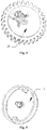
Figure 3 is a schematic view showing the structure of a rotary self-locking mechanism of a telephone wire withdrawing device according to the present application; -
Figure 4 is a schematic view showing the structure of a toothed component in a telephone wire withdrawing device; -
Figure 5 is a schematic view showing the structure of a base in a telephone wire withdrawing device; -
Figure 6 is a schematic view partially showing the structures of a toothed component, a base, a resilient sheet and a swing piece in a telephone wire withdrawing device; -
Figure 7 is a schematic view showing a state of a toothed component, a base, a resilient sheet and a swing piece in a telephone wire withdrawing device; -
Figure 8 is a schematic view showing another state of a toothed component, a base, a resilient sheet and a swing piece of a telephone wire withdrawing device; -
Figure 9 is a schematic view showing another state of a toothed component, a base, a resilient sheet and a swing piece of a telephone wire withdrawing device; -
Figure 10 is a schematic view showing another state of a toothed component, a base, a resilient sheet and a swing piece of a telephone wire withdrawing device; -
Figure 11 is a schematic view showing another state of a toothed component, a base, a resilient sheet and a swing piece of a telephone wire withdrawing device; -
Figure 12 is a schematic view showing another state of a toothed component, a base, a resilient sheet and a swing piece of a telephone wire withdrawing device; -
Figure 13 is a schematic view showing another state of a toothed component, a base, a resilient sheet and a swing piece of a telephone wire withdrawing device; and -
Figure 14 is a schematic view showing another state of a toothed component, a base, a resilient sheet and a swing piece of a telephone wire withdrawing device. - A telephone wire withdrawing device is provided according to an embodiment of the present application, to achieve pulling and withdrawing functions of a telephone wire so as to obtain a smooth operation and improve the user experience, and further to avoid the call distortion caused by an electric brush due to the fact that the electric brush is not necessarily used by the telephone wire withdrawing device.
- In order to make the objects, features and advantages of the present application be more obvious and easy to understand, the technical solutions in the embodiments of the present application will be described clearly and completely hereinafter in conjunction with the drawings in the embodiments of the present application. Apparently, the described embodiments are only a part of the embodiments of the present application, rather than all embodiments. Based on the embodiments in the present application, all of other embodiments, made by the person skilled in the art without any creative efforts, fall into the scope of the present application.
- Referring to
Figures 1 to 14 , an embodiment of a telephone wire withdrawing device according to the present application includes: aslider 1, a frame 2, ahandset 3, a telephone wire 4, a roller A5, a rotary self-locking mechanism 6, a roller B7, and an extension spring 8. - The rotary self-locking mechanism includes a
base 9, atoothed component 10, aswing piece 11, a resilient sheet A 12 and a resilient sheet B13. - The
slider 1 is fitted in a guidingslot 14 of the frame 2, and can slide cooperatively in the guidingslot 14. - The roller A5 is fixed on the
slider 1. - The telephone wire 4 has one end fixed on the frame 2, and another end rounding the roller A5 and connected to the
handset 3. It should be noted that, as shown inFigure 2 , the telephone wire 4 may have one end fixed on a position Z on the frame 2, and another end rounding the roller A5 and being connected to thehandset 3. - The roller B7 is fixed on the frame 2.
- The extension spring 8 has one end fixed on the frame 2 and another end rounding the roller B7 and being connected to the
slider 1, which is configured to provide a restoring force for theslider 1 in the case that theslider 1 slides cooperatively in the guidingslot 14. It should be noted that, as shown inFigure 2 , the extension spring 8 has one end fixed at a position Y on the frame 2 and another end rounding the roller B7 and being connected at the position X on theslider 1. - The frame 2 is provided with a rack-
like groove 15, and the rack-like groove 15 and thetoothed component 10 of the rotary self-locking mechanism 6 constitute a gear-rack-like structure. - The
base 9 of the rotary self-locking mechanism 6 is fixed on theslider 1, and in the case that theslider 1 slides cooperatively in the guidingslot 14, thetoothed component 10 of the rotary self-locking mechanism 6 meshes and rolls in the rack-like groove 15 of the frame 2 to achieve a relative rotation between thebase 9 and thetoothed component 10 of the rotary self-locking mechanism 6. - The
swing piece 11, the resilient sheet A12 and the resilient sheet B13 are fixed on thetoothed component 10. - It should be noted that, the
toothed component 10 is provided with teeth on a rim thereof and the teeth mesh with the rack-like groove 15; - The
swing piece 11 has a central shaft fixed on thetoothed component 10, and theswing piece 11 rotates on thetoothed component 10 about the central shaft. - The
swing piece 11 is provided with a position-limitingprotrusion 17. - The resilient sheet B13 is provided with a position-limiting
bump 18. - The
slider 1 cooperatively slides upwards or downwards in the guidingslot 14. - The
base 9 is provided with two L-shapedlug bosses 16, and the two L-shapedlug bosses 16 are symmetrical about a central axis of thebase 9. - (1) The drawing and withdrawing functions of the telephone wire withdrawing device according to this embodiment is performed by the following process.
As shown inFigures 1 and 2 , theslider 1 is fitted in the guidingslot 14 of the frame 2, and theslider 1 is slidable upward or downward direction along the guidingslot 14 in the guidingslot 14 of the frame 2. Particularly, when the user picks up thehandset 3, theslider 1 may slide upwardly, and when the user hangs up thehandset 3 , theslider 1 may drive the telephone wire 4 to move downwardly under the action of the extension spring 8. - (2) The function of achieving a fixed length of the telephone wire by the telephone wire withdrawing device according to this embodiment is performed by the following process.
As shown inFigure 2 , when the user picks up thehandset 3, theslider 1 may slide upwardly, and a length of the telephone wire 4 being drawn out may be increased. Thetoothed component 10 may drive theswing piece 11 to counterclockwise rotate about a center of rotation V under the action of the gear-rack-like structure. Reference is made inFigures 6, 7 and8 . InFigure 6 , theswing piece 11 is in a free state and is freely rotatable about a rotation center W. In the case that thetoothed component 10 drives theswing piece 11 to counterclockwise rotate and reaches a state shown inFigure 7 , the L-shapedlug boss 16 of thebase 9 may press down theswing piece 11, the resilient sheet A12 provides a supporting force for theswing piece 11, and the limiting position protrusion of theswing piece 11 may be rotated to a position above the limiting position bump of the resilient sheet B13. When theswing piece 11 rotates counterclockwise and reaches a state shown inFigure 8 , the position-limitingprotrusion 17 of theswing piece 11 may abut against the position-limitingbump 18 of the resilient sheet B13 under the action of the supporting force of the resilient sheet A12. When the user continues to pull out the telephone wire 4, the rotary self-locking mechanism 6 may repeat the states shown inFigures 7 and8 and may not be locked. When thehandset 3 is released by the user, the telephone wire 4 may also be released, and theslider 1 may drive the rotary self-locking mechanism 6 to move downwardly under the restoring force of the extension spring 8. Also, a length of the telephone wire 4 being pulled out may be shortened to some extent. In such a case, thetoothed component 10 may drive theswing piece 11 to rotate clockwise under the action of the gear-rack-like structure. As shown inFigures 9, 10 and11 , in the case that thetoothed component 10 drives theswing piece 11 to rotate clockwise, theswing piece 11 may contact with the L-shapedlug boss 16 of thebase 9, and reaches a state shown inFigure 11 under the action of a rotating force. In such case, the position-limitingbump 18 of the resilient sheet B13 presses on the position-limitingprotrusion 17 of theswing piece 11 and provides a supporting force for theswing piece 11, thus preventing theswing piece 11 from continuing to rotate clockwise and accordingly preventing the resilient sheet B13, the resilient sheet A12 and thetoothed component 10 from rotating clockwise, and theswing piece 11 and thetoothed component 10 are in a clockwise self-locking state. At this moment, theslider 1 may be fixed at a certain position in the guidingslot 14 of the frame 2 under a combined action of the extension spring 8 and the self-locking state of the rotary self-locking mechanism 6. In this case, the telephone wire 4 at the handset end may have a certain fixed length to allow the user to freely move during calls, thus providing a better calling experience for the user. - (3) The function of automatic withdrawing of the telephone wire by the telephone wire withdrawing device according to this embodiment is specifically performed by the following process.
- As shown in
Figure 2 , after the user finishes the call, the user may slightly pull the telephone wire 4 upwardly to straighten the telephone wire 4 and bring theslider 1 to move upwardly by a short distance. Then, thetoothed component 10 may drive theswing piece 11 to rotate counterclockwise under the action of the gear-rack-like structure. As shown inFigure 12 , when the mechanism reaches a state shown inFigure 12 , the position-limitingbump 18 of the resilient sheet B13 is pressed on the position-limitingprotrusion 17 of theswing piece 11 to provide a force for rotating theswing piece 11 counterclockwise, and theswing piece 11 may rotate counterclockwise by a certain degree under the force provided by the resilient sheet B13 and then rotates to a state shown inFigure 13 . At this moment, if the user hangs up thehandset 3, theslider 1 may drive the telephone wire 4 to move downwardly under the action of the extension spring 8, and thetoothed component 10 may drive theswing piece 11 to rotate clockwise under the action of the gear-rack-like structure. As shown inFigure 14 , the L-shapedlug boss 16 of the base 2, and theswing piece 11 may not limit the downward movement of theslider 1, thus achieving the automatic withdrawing function of the telephone wire. - In this embodiment, a telephone wire withdrawing device includes a
slider 1, a frame 2, ahandset 3, a telephone wire 4, a roller A5, a rotary self-locking mechanism 6, a roller B7 and an extension spring 8. The rotary self-locking mechanism includes abase 9, atoothed component 10, aswing piece 11, a resilient sheet A12, and a resilient sheet B13. Theslider 1 is fitted in the guidingslot 14 of the frame 2, and slides cooperatively in the guidingslot 14. The roller A5 is fixed on theslider 1. The telephone wire 4 has one end fixed on the frame 2, and another end rounding the roller A5 and connected in thehandset 3. The roller B7 is fixed on the frame 2. The extension spring 8 has one end fixed on the frame 2, and has another end rounding the roller B7 and connected on theslider 1 to provide a restoring force for theslider 1 in the case that theslider 1 slides cooperatively in the guidingslot 14. The frame 2 is provided with a rack-like groove 15, and the rack-like groove 15 and thetoothed component 10 of the rotary self-locking mechanism 6 constitute a gear-rack-like structure. Thebase 9 of the rotary self-locking mechanism 6 is fixed on theslider 1, and in the case that theslider 1 slides cooperatively in the guidingslot 14, thetoothed component 10 of the rotary self-locking mechanism 6 meshes and rolls in the rack-like groove 15 of the frame 2 to realize a relative rotation between thebase 9 and thetoothed component 10 of the rotary self-locking mechanism 6. Theswing piece 11, the resilient sheet A12 and the resilient sheet B13 are fixed on thetoothed component 10. Thebase 9 is provided with at least one L-shapedlug boss 16. In this embodiment, the telephone wire 4 connected to thehandset 3 may slide in the guidingslot 14 of the frame 2 via the roller A5 and theslider 1 to realize the pulling function of the telephone wire, and with a restoring force for theslider 1 provided by the extension spring 8, the withdrawing function of the telephone wire may be achieved. Furthermore, since when theslider 1 slides cooperatively in the guidingslot 14, thetoothed component 10 meshes and rolls in the rack-like groove 15 of the frame 2, the operations during drawing and withdrawing of the telephone wire 4 are smooth, thus improving the user experience. In addition, since it is unnecessary to use an electric brush, the call distortion caused by the electric brush is avoided. Moreover, a telephone wire withdrawing device according to this embodiment realizes the function of achieving a fixed length of the telephone wire and the function of automatic withdrawing of the telephone wire, thereby providing a better user experience. - A telephone wire withdrawing device according to this embodiment has the advantages of a simple structure, an easy maintenance, a high reliability, a simple operation, a safety design and a low cost. The telephone wire have a variable fixed length and can realize the automatic withdrawing function , thus is very suitable to apply to a calling device in the public place with a harsh service environment.
- For ease of understanding, a telephone wire withdrawing device according to an embodiment of the present application used in a practical application scenario is described hereinafter according to the embodiments shown in
Figures 1 to 14 . - A: When a user picks up the
handset 3, theslider 1 may slide upwardly, and a length of the telephone wire 4 being pulled out may be increased. - B: When the user pulls out the
handset 3 by an appropriate length, the user stops pulling out the telephone wire 4, at this moment under the action of the rotary self-locking mechanism 6, this appropriate length of the telephone wire 4 is maintained, and the telephone wire is brought into a locking state, thus the telephone wire 4 cannot be withdrawn any more. - C: When the user makes a call via the
handset 3 and needs to withdraw the telephone wire 4 after ending the call, the user holds thehandset 3 and pulls out the telephone wire 4 by a short distance, then the user moveshandset 3 in the withdrawing direction, at this moment, the locking state of the rotary self-locking mechanism 6 is released. - D: After the locking state is released, the user continues to move the
handset 3 in the withdrawing direction, and the telephone wire 4 is gradually withdrawn until the telephone wire 4 is withdrawn to an initial length. Then, the user hangs up thehandset 3 and the calling process finishes. - Those skilled in the art may clearly understand that, for a convenient and simple description, the specific operation process of the system, the device and the unit described above may refer to the corresponding process in the above embodiments of the method, thus is not described in detail hereinafter.
- In the several embodiments according to the present application, it should be appreciated that, the method, the device and the system disclosed herein may be implemented in other manners. For example, the embodiments of the device described above are only schematic. For example, the division of the units is only a division according to the logical functions, and there may be other division modes in the practical implementation, for instant, multiple units or components may be combined, or may be integrated into another system, or some features may be omitted or may be not performed. In addition, the coupling, direct coupling or communication connection between the components displayed or discussed above may be realized by some interfaces. The indirect coupling or communication connection between the devices or units may be electrical, mechanical or be of other forms.
- The above unit described as a separate component may be or may be not physically separate. The component displayed as a unit may be or may be not a physical unit, that is, may be located at one place or may be distributed on multiple network units. The object of the solution of the embodiment may be achieved by selecting a part or all of the units according to the practical demands.
- Furthermore, various function units in the embodiments of the present application may be integrated in one processing unit; or, each of the function units may be a single unit; or two or more function units are integrated in one unit. The above integrated unit may be realized in the form of hardware or in the form of software function unit.
- In the case that the integrated unit is implemented in the form of software function unit and is sold or used as a separate product, it can also be stored in a computer readable storage medium. Based on such understanding, the essence of the technical solutions of the present application, or the part that contributes to the conventional technology, or all or part of the technical solutions of embodiments of the present application may be embodied in the form of a software product. The computer software product is stored in a storage medium, and includes several instructions which enables a computer device (which may be a personal computer, a server, or a network device, etc.) to execute all or part steps of the method of each embodiment of the present application. The storage medium described above includes various medium which may store program codes, such as a USB disk, a mobile hard disk drive, a Read-Only Memory (ROM), a Random Access Memory (RAM), a magnetic disc or an optical disc.
- The above embodiments are only intended for describing the technical solutions of the present application, and should not be interpreted as limitation to the present application. Although the present application is described in detail in conjunction with the above embodiments, it should be understood that, for those skilled in the art, modifications may be made to the technical solutions of the above embodiments, or equivalent substitutions may be made to part or all of the technical features in the technical solutions; and theses modifications and substitutions made to the essence of the corresponding technical solution also fall into the spirit and scope defined by the technical solution of the present application.
| 1 | slider, | 2 | frame, |
| 3 | handset, | 4 | telephone wire, |
| A5 | roller, | 6 | rotary self-locking mechanism, |
| B7 | roller, | 8 | extension spring, |
| 9 | base, | 10 | toothed component, |
| 11 | swing piece, | A12 | resilient sheet, |
| B13 | resilient sheet, | 14 | guiding slot, |
| 15 | rack-like groove, | 16 | L-shaped lug boss, |
| 17 | position-limiting protrusion of the |
||
| 18 | position-limiting bump of the resilient sheet B13, | ||
| Y | position on the frame 2, | Z | position on the frame 2, |
| X | position on the |
V | rotation center of |
| W | rotation center of |
11. | |
Claims (7)
- A telephone wire withdrawing device, comprising a slider (1), a frame (2), a handset (3), a telephone wire (4), a roller (A5), a rotary self-locking mechanism (6), a roller (B7), and an extension spring (8), whereinthe rotary self-locking mechanism comprises a base (9), a toothed component (10), a swing piece (11), a resilient sheet (A12), and a resilient sheet (B13);the slider (1) is fitted in a guiding slot (14) of the frame (2), and slides cooperatively in the guiding slot (14);the roller (A5) is fixed to the slider (1);the telephone wire (4) has one end fixed on the frame (2) and another end rounding the roller (A5) and being connected to the handset (3);the roller (B7) is fixed to the frame (2);the extension spring (8) has one end fixed to the frame (2) and another end rounding the roller (B7) and being connected to the slider (1), and provides a restoring force for the slider (1) when the slider (1) slides cooperatively in the guiding slot (14);the frame (2) is provided with a rack-like groove (15), and the rack-like groove (15) and the toothed component (10) of the rotary self-locking mechanism (6) constitute a gear-rack-like structure;the base (9) of the rotary self-locking mechanism (6) is fixed on the slider (1), and when the slider (1) slides cooperatively in the guiding slot (14), the toothed component (10) of the rotary self-locking mechanism (6) meshes with the rack-like groove (15) of the frame (2) and rolls in the rack-like groove (15) of the frame (2) to realize a relative rotation between the toothed component (10) and the base (9) of the rotary self-locking mechanism (6);the swing piece (11), the resilient sheet (A12) and the resilient sheet (B13) are fixed on the toothed component (10); andthe base (9) is provided with at least one L-shaped lug boss (16).
- The telephone wire withdrawing device according to claim 1, wherein teeth are provided on a rim of the toothed component (10), and the toothed component (10) meshes with the rack-like groove (15).
- The telephone wire withdrawing device according to claim 1, wherein the swing piece (11) has a central shaft fixed on the toothed component (10), and the swing piece (11) rotates about the central shaft at the toothed component (10).
- The telephone wire withdrawing device according to claim 1, wherein the swing piece (11) is provided with a position-limiting protrusion.
- The telephone wire withdrawing device according to claim 1, wherein the resilient sheet (B13) is provided with a position-limiting bump.
- The telephone wire withdrawing device according to claim 1, wherein the slider (1) cooperatively slides upwards or downwards in the guiding slot (14).
- The telephone wire withdrawing device according to any one of claims 1 to 6, wherein the base (9) is provided with two L-shaped lug bosses, and the two L-shaped lug bosses are symmetrical about a central axis of the base (9).
Applications Claiming Priority (2)
| Application Number | Priority Date | Filing Date | Title |
|---|---|---|---|
| CN201410132031.2A CN103873623B (en) | 2014-04-02 | 2014-04-02 | A kind of recovery telephone wire device |
| PCT/CN2014/092008 WO2015149529A1 (en) | 2014-04-02 | 2014-11-24 | Telephone wire withdrawing device |
Publications (3)
| Publication Number | Publication Date |
|---|---|
| EP3127846A1 true EP3127846A1 (en) | 2017-02-08 |
| EP3127846A4 EP3127846A4 (en) | 2017-05-31 |
| EP3127846B1 EP3127846B1 (en) | 2018-07-25 |
Family
ID=50911736
Family Applications (1)
| Application Number | Title | Priority Date | Filing Date |
|---|---|---|---|
| EP14888547.8A Not-in-force EP3127846B1 (en) | 2014-04-02 | 2014-11-24 | Telephone wire withdrawing device |
Country Status (7)
| Country | Link |
|---|---|
| US (1) | US9884741B2 (en) |
| EP (1) | EP3127846B1 (en) |
| CN (1) | CN103873623B (en) |
| AU (1) | AU2014389086B2 (en) |
| CL (1) | CL2016001481A1 (en) |
| TR (1) | TR201815830T4 (en) |
| WO (1) | WO2015149529A1 (en) |
Families Citing this family (12)
| Publication number | Priority date | Publication date | Assignee | Title |
|---|---|---|---|---|
| CN103873623B (en) * | 2014-04-02 | 2016-09-28 | 广州广电运通金融电子股份有限公司 | A kind of recovery telephone wire device |
| CN104320514B (en) * | 2014-11-04 | 2017-11-17 | 广州御银自动柜员机科技有限公司 | Anti-riot telephone wire machine for automatically recovering structure |
| CN104869186B (en) * | 2015-04-20 | 2018-03-13 | 杭州九聚科技有限公司 | Phone spooler |
| CN107140482A (en) * | 2017-06-07 | 2017-09-08 | 佛山市建金建电子科技有限公司 | A kind of optical fiber receiver |
| CN107140483A (en) * | 2017-07-06 | 2017-09-08 | 林素霞 | The power delivery cable of external equipment |
| CN108233150B (en) * | 2017-12-19 | 2019-07-12 | 鹤山市亿源电器实业有限公司 | A kind of automatic producing device of intelligent socket |
| ES2721726A1 (en) * | 2018-01-30 | 2019-08-05 | Albiral Display Solutions Sl | SET OF HIDDEN APPLIANCE, SYSTEM INCLUDING IT AND CONTROL METHOD OF THE SAME (Machine-translation by Google Translate, not legally binding) |
| CN109335897B (en) * | 2018-10-16 | 2020-06-16 | 钱钢 | Movable lead wire winding and unwinding device |
| CN109353899B (en) * | 2018-11-01 | 2020-06-19 | 上海赛飞航空线缆制造有限公司 | Wire coiling device |
| CN109775475B (en) * | 2019-01-28 | 2021-04-27 | 北京神州数码云科信息技术有限公司 | A device for accommodating computer cables |
| CN112744646B (en) * | 2019-10-29 | 2024-06-21 | 富鼎电子科技(嘉善)有限公司 | Automatic power line winding mechanism |
| CN119452538A (en) * | 2022-04-25 | 2025-02-14 | 易格斯有限公司 | Feed-in system for electrical lines, in particular charging cables for electric vehicles |
Family Cites Families (16)
| Publication number | Priority date | Publication date | Assignee | Title |
|---|---|---|---|---|
| US5421530A (en) * | 1993-11-23 | 1995-06-06 | Hughes-Avicom International, Inc. | Cord retractor mechanism |
| JP2000063047A (en) * | 1998-08-25 | 2000-02-29 | Marusu Denshi:Kk | Cord relay device and cord reel device employing said cord relay device |
| GB2351485A (en) * | 1999-06-30 | 2001-01-03 | Alan Vanner | Storage device for an electrical cable having an earpiece |
| GB9922976D0 (en) * | 1999-09-28 | 1999-12-01 | Khan Azam | Electronic apparatus with cable storage arrangement |
| CN2462596Y (en) * | 2001-01-05 | 2001-11-28 | 深圳市龙岗区平湖启盛制品厂 | Telephone line reeling box able to control line length |
| TW510356U (en) * | 2001-05-14 | 2002-11-11 | Sheng-Shing Liau | Wire winding case with an electric charging unit |
| CN2494084Y (en) * | 2001-06-24 | 2002-05-29 | 神达电脑股份有限公司 | Fax/Modem Internal Hub |
| CN2494566Y (en) * | 2001-07-20 | 2002-06-05 | 杨文钦 | Telephone extension cord reel |
| CN2507197Y (en) * | 2001-10-19 | 2002-08-21 | 天津四通电脑设备有限公司 | Telephone line winder box |
| US20080156922A1 (en) * | 2007-01-03 | 2008-07-03 | Vira Manufacturing, Inc. | Apparatus for secure display of small electronic devices having an essential signal or power cord |
| CN201080394Y (en) * | 2007-07-13 | 2008-07-02 | 黄耀贤 | Winding box with non-return mechanism |
| US9352932B2 (en) * | 2009-06-11 | 2016-05-31 | Rgb Systems, Inc. | Speed control for cable retractor |
| US8740127B2 (en) * | 2009-06-11 | 2014-06-03 | Rgb Systems, Inc. | Cable retractor |
| US8469305B2 (en) * | 2011-01-07 | 2013-06-25 | Crestron Electronics Inc. | Cable cord retractor |
| US8469303B2 (en) * | 2011-01-07 | 2013-06-25 | Crestron Electronics Inc. | Cable cord retractor |
| CN103873623B (en) * | 2014-04-02 | 2016-09-28 | 广州广电运通金融电子股份有限公司 | A kind of recovery telephone wire device |
-
2014
- 2014-04-02 CN CN201410132031.2A patent/CN103873623B/en active Active
- 2014-11-24 TR TR2018/15830T patent/TR201815830T4/en unknown
- 2014-11-24 EP EP14888547.8A patent/EP3127846B1/en not_active Not-in-force
- 2014-11-24 WO PCT/CN2014/092008 patent/WO2015149529A1/en not_active Ceased
- 2014-11-24 AU AU2014389086A patent/AU2014389086B2/en not_active Ceased
- 2014-11-24 US US15/100,271 patent/US9884741B2/en not_active Expired - Fee Related
-
2016
- 2016-06-13 CL CL2016001481A patent/CL2016001481A1/en unknown
Also Published As
| Publication number | Publication date |
|---|---|
| CN103873623A (en) | 2014-06-18 |
| EP3127846B1 (en) | 2018-07-25 |
| US9884741B2 (en) | 2018-02-06 |
| EP3127846A4 (en) | 2017-05-31 |
| CL2016001481A1 (en) | 2016-12-16 |
| AU2014389086B2 (en) | 2017-03-02 |
| WO2015149529A1 (en) | 2015-10-08 |
| AU2014389086A1 (en) | 2016-06-09 |
| TR201815830T4 (en) | 2018-11-21 |
| US20170001828A1 (en) | 2017-01-05 |
| CN103873623B (en) | 2016-09-28 |
Similar Documents
| Publication | Publication Date | Title |
|---|---|---|
| EP3127846A1 (en) | Telephone wire withdrawing device | |
| CN205945842U (en) | Flexible display device and mobile terminal | |
| EP3157231B1 (en) | Mobile terminal and sim card tray thereof having a button structure | |
| CN111150189B (en) | Intelligent wrist strap equipment | |
| EP3564790A1 (en) | Flexible electronic device | |
| WO2018049678A1 (en) | Base, mobile terminal, headphone, and headphone base | |
| CN104089155B (en) | A kind of extending means | |
| KR200485875Y1 (en) | Apparatus for reeling an ear-phone cable | |
| CN110418533B (en) | Electronic equipment | |
| CN221041670U (en) | Docking station with dust cover capable of sliding smoothly | |
| CN217281438U (en) | Low-cost composite structure ultrathin card seat | |
| CN211853233U (en) | Novel jam-proof security protection communications facilities | |
| CN210667970U (en) | Power frequency partial discharge-free test transformer | |
| CN214849418U (en) | USB charging wire convenient to accomodate | |
| CN218041580U (en) | Intelligent conference telephone | |
| CN216313551U (en) | Remote control device of monitoring pump | |
| CN214901162U (en) | Multimedia playing terminal | |
| CN212433801U (en) | Data mobile storage device based on electronic communication equipment | |
| CN214756646U (en) | Remote video conference system terminal | |
| CN103676421B (en) | Electronic installation | |
| KR101285252B1 (en) | Cellular phone case with supports | |
| CN210724925U (en) | Can support cell-phone protective sheath | |
| CN215581250U (en) | Smart phone with rotary camera structure | |
| CN220066079U (en) | Wifi antenna structure of wireless IP telephone | |
| CN217508829U (en) | Cell-phone shell with support function |
Legal Events
| Date | Code | Title | Description |
|---|---|---|---|
| PUAI | Public reference made under article 153(3) epc to a published international application that has entered the european phase |
Free format text: ORIGINAL CODE: 0009012 |
|
| 17P | Request for examination filed |
Effective date: 20160602 |
|
| AK | Designated contracting states |
Kind code of ref document: A1 Designated state(s): AL AT BE BG CH CY CZ DE DK EE ES FI FR GB GR HR HU IE IS IT LI LT LU LV MC MK MT NL NO PL PT RO RS SE SI SK SM TR |
|
| AX | Request for extension of the european patent |
Extension state: BA ME |
|
| REG | Reference to a national code |
Ref country code: DE Ref legal event code: R079 Ref document number: 602014029367 Country of ref document: DE Free format text: PREVIOUS MAIN CLASS: B65H0075480000 Ipc: B65H0075360000 |
|
| A4 | Supplementary search report drawn up and despatched |
Effective date: 20170503 |
|
| RIC1 | Information provided on ipc code assigned before grant |
Ipc: B65H 75/44 20060101ALI20170425BHEP Ipc: B65H 75/36 20060101AFI20170425BHEP |
|
| DAX | Request for extension of the european patent (deleted) | ||
| GRAP | Despatch of communication of intention to grant a patent |
Free format text: ORIGINAL CODE: EPIDOSNIGR1 |
|
| INTG | Intention to grant announced |
Effective date: 20180227 |
|
| GRAS | Grant fee paid |
Free format text: ORIGINAL CODE: EPIDOSNIGR3 |
|
| GRAA | (expected) grant |
Free format text: ORIGINAL CODE: 0009210 |
|
| AK | Designated contracting states |
Kind code of ref document: B1 Designated state(s): AL AT BE BG CH CY CZ DE DK EE ES FI FR GB GR HR HU IE IS IT LI LT LU LV MC MK MT NL NO PL PT RO RS SE SI SK SM TR |
|
| REG | Reference to a national code |
Ref country code: GB Ref legal event code: FG4D |
|
| REG | Reference to a national code |
Ref country code: CH Ref legal event code: EP |
|
| REG | Reference to a national code |
Ref country code: AT Ref legal event code: REF Ref document number: 1021520 Country of ref document: AT Kind code of ref document: T Effective date: 20180815 |
|
| REG | Reference to a national code |
Ref country code: IE Ref legal event code: FG4D |
|
| REG | Reference to a national code |
Ref country code: DE Ref legal event code: R096 Ref document number: 602014029367 Country of ref document: DE |
|
| REG | Reference to a national code |
Ref country code: NL Ref legal event code: MP Effective date: 20180725 |
|
| REG | Reference to a national code |
Ref country code: LT Ref legal event code: MG4D |
|
| PG25 | Lapsed in a contracting state [announced via postgrant information from national office to epo] |
Ref country code: NL Free format text: LAPSE BECAUSE OF FAILURE TO SUBMIT A TRANSLATION OF THE DESCRIPTION OR TO PAY THE FEE WITHIN THE PRESCRIBED TIME-LIMIT Effective date: 20180725 |
|
| PG25 | Lapsed in a contracting state [announced via postgrant information from national office to epo] |
Ref country code: GR Free format text: LAPSE BECAUSE OF FAILURE TO SUBMIT A TRANSLATION OF THE DESCRIPTION OR TO PAY THE FEE WITHIN THE PRESCRIBED TIME-LIMIT Effective date: 20181026 Ref country code: NO Free format text: LAPSE BECAUSE OF FAILURE TO SUBMIT A TRANSLATION OF THE DESCRIPTION OR TO PAY THE FEE WITHIN THE PRESCRIBED TIME-LIMIT Effective date: 20181025 Ref country code: PL Free format text: LAPSE BECAUSE OF FAILURE TO SUBMIT A TRANSLATION OF THE DESCRIPTION OR TO PAY THE FEE WITHIN THE PRESCRIBED TIME-LIMIT Effective date: 20180725 Ref country code: RS Free format text: LAPSE BECAUSE OF FAILURE TO SUBMIT A TRANSLATION OF THE DESCRIPTION OR TO PAY THE FEE WITHIN THE PRESCRIBED TIME-LIMIT Effective date: 20180725 Ref country code: SE Free format text: LAPSE BECAUSE OF FAILURE TO SUBMIT A TRANSLATION OF THE DESCRIPTION OR TO PAY THE FEE WITHIN THE PRESCRIBED TIME-LIMIT Effective date: 20180725 Ref country code: FI Free format text: LAPSE BECAUSE OF FAILURE TO SUBMIT A TRANSLATION OF THE DESCRIPTION OR TO PAY THE FEE WITHIN THE PRESCRIBED TIME-LIMIT Effective date: 20180725 Ref country code: IS Free format text: LAPSE BECAUSE OF FAILURE TO SUBMIT A TRANSLATION OF THE DESCRIPTION OR TO PAY THE FEE WITHIN THE PRESCRIBED TIME-LIMIT Effective date: 20181125 Ref country code: LT Free format text: LAPSE BECAUSE OF FAILURE TO SUBMIT A TRANSLATION OF THE DESCRIPTION OR TO PAY THE FEE WITHIN THE PRESCRIBED TIME-LIMIT Effective date: 20180725 Ref country code: BG Free format text: LAPSE BECAUSE OF FAILURE TO SUBMIT A TRANSLATION OF THE DESCRIPTION OR TO PAY THE FEE WITHIN THE PRESCRIBED TIME-LIMIT Effective date: 20181025 |
|
| PGFP | Annual fee paid to national office [announced via postgrant information from national office to epo] |
Ref country code: DE Payment date: 20181127 Year of fee payment: 5 |
|
| PG25 | Lapsed in a contracting state [announced via postgrant information from national office to epo] |
Ref country code: AL Free format text: LAPSE BECAUSE OF FAILURE TO SUBMIT A TRANSLATION OF THE DESCRIPTION OR TO PAY THE FEE WITHIN THE PRESCRIBED TIME-LIMIT Effective date: 20180725 Ref country code: LV Free format text: LAPSE BECAUSE OF FAILURE TO SUBMIT A TRANSLATION OF THE DESCRIPTION OR TO PAY THE FEE WITHIN THE PRESCRIBED TIME-LIMIT Effective date: 20180725 Ref country code: HR Free format text: LAPSE BECAUSE OF FAILURE TO SUBMIT A TRANSLATION OF THE DESCRIPTION OR TO PAY THE FEE WITHIN THE PRESCRIBED TIME-LIMIT Effective date: 20180725 |
|
| PGFP | Annual fee paid to national office [announced via postgrant information from national office to epo] |
Ref country code: IT Payment date: 20181123 Year of fee payment: 14 Ref country code: GB Payment date: 20181219 Year of fee payment: 5 |
|
| REG | Reference to a national code |
Ref country code: DE Ref legal event code: R097 Ref document number: 602014029367 Country of ref document: DE |
|
| PG25 | Lapsed in a contracting state [announced via postgrant information from national office to epo] |
Ref country code: EE Free format text: LAPSE BECAUSE OF FAILURE TO SUBMIT A TRANSLATION OF THE DESCRIPTION OR TO PAY THE FEE WITHIN THE PRESCRIBED TIME-LIMIT Effective date: 20180725 Ref country code: RO Free format text: LAPSE BECAUSE OF FAILURE TO SUBMIT A TRANSLATION OF THE DESCRIPTION OR TO PAY THE FEE WITHIN THE PRESCRIBED TIME-LIMIT Effective date: 20180725 Ref country code: ES Free format text: LAPSE BECAUSE OF FAILURE TO SUBMIT A TRANSLATION OF THE DESCRIPTION OR TO PAY THE FEE WITHIN THE PRESCRIBED TIME-LIMIT Effective date: 20180725 Ref country code: CZ Free format text: LAPSE BECAUSE OF FAILURE TO SUBMIT A TRANSLATION OF THE DESCRIPTION OR TO PAY THE FEE WITHIN THE PRESCRIBED TIME-LIMIT Effective date: 20180725 |
|
| PG25 | Lapsed in a contracting state [announced via postgrant information from national office to epo] |
Ref country code: SK Free format text: LAPSE BECAUSE OF FAILURE TO SUBMIT A TRANSLATION OF THE DESCRIPTION OR TO PAY THE FEE WITHIN THE PRESCRIBED TIME-LIMIT Effective date: 20180725 Ref country code: DK Free format text: LAPSE BECAUSE OF FAILURE TO SUBMIT A TRANSLATION OF THE DESCRIPTION OR TO PAY THE FEE WITHIN THE PRESCRIBED TIME-LIMIT Effective date: 20180725 Ref country code: SM Free format text: LAPSE BECAUSE OF FAILURE TO SUBMIT A TRANSLATION OF THE DESCRIPTION OR TO PAY THE FEE WITHIN THE PRESCRIBED TIME-LIMIT Effective date: 20180725 |
|
| PLBE | No opposition filed within time limit |
Free format text: ORIGINAL CODE: 0009261 |
|
| STAA | Information on the status of an ep patent application or granted ep patent |
Free format text: STATUS: NO OPPOSITION FILED WITHIN TIME LIMIT |
|
| REG | Reference to a national code |
Ref country code: CH Ref legal event code: PL |
|
| 26N | No opposition filed |
Effective date: 20190426 |
|
| PG25 | Lapsed in a contracting state [announced via postgrant information from national office to epo] |
Ref country code: LU Free format text: LAPSE BECAUSE OF NON-PAYMENT OF DUE FEES Effective date: 20181124 Ref country code: MC Free format text: LAPSE BECAUSE OF FAILURE TO SUBMIT A TRANSLATION OF THE DESCRIPTION OR TO PAY THE FEE WITHIN THE PRESCRIBED TIME-LIMIT Effective date: 20180725 |
|
| REG | Reference to a national code |
Ref country code: BE Ref legal event code: MM Effective date: 20181130 |
|
| REG | Reference to a national code |
Ref country code: IE Ref legal event code: MM4A |
|
| PG25 | Lapsed in a contracting state [announced via postgrant information from national office to epo] |
Ref country code: CH Free format text: LAPSE BECAUSE OF NON-PAYMENT OF DUE FEES Effective date: 20181130 Ref country code: SI Free format text: LAPSE BECAUSE OF FAILURE TO SUBMIT A TRANSLATION OF THE DESCRIPTION OR TO PAY THE FEE WITHIN THE PRESCRIBED TIME-LIMIT Effective date: 20180725 Ref country code: LI Free format text: LAPSE BECAUSE OF NON-PAYMENT OF DUE FEES Effective date: 20181130 |
|
| PG25 | Lapsed in a contracting state [announced via postgrant information from national office to epo] |
Ref country code: IE Free format text: LAPSE BECAUSE OF NON-PAYMENT OF DUE FEES Effective date: 20181124 |
|
| PG25 | Lapsed in a contracting state [announced via postgrant information from national office to epo] |
Ref country code: BE Free format text: LAPSE BECAUSE OF NON-PAYMENT OF DUE FEES Effective date: 20181130 |
|
| PG25 | Lapsed in a contracting state [announced via postgrant information from national office to epo] |
Ref country code: MT Free format text: LAPSE BECAUSE OF NON-PAYMENT OF DUE FEES Effective date: 20181124 |
|
| PGFP | Annual fee paid to national office [announced via postgrant information from national office to epo] |
Ref country code: TR Payment date: 20191111 Year of fee payment: 6 Ref country code: AT Payment date: 20191129 Year of fee payment: 6 |
|
| REG | Reference to a national code |
Ref country code: AT Ref legal event code: UEP Ref document number: 1021520 Country of ref document: AT Kind code of ref document: T Effective date: 20180725 |
|
| PG25 | Lapsed in a contracting state [announced via postgrant information from national office to epo] |
Ref country code: PT Free format text: LAPSE BECAUSE OF FAILURE TO SUBMIT A TRANSLATION OF THE DESCRIPTION OR TO PAY THE FEE WITHIN THE PRESCRIBED TIME-LIMIT Effective date: 20180725 |
|
| REG | Reference to a national code |
Ref country code: DE Ref legal event code: R119 Ref document number: 602014029367 Country of ref document: DE |
|
| PG25 | Lapsed in a contracting state [announced via postgrant information from national office to epo] |
Ref country code: HU Free format text: LAPSE BECAUSE OF FAILURE TO SUBMIT A TRANSLATION OF THE DESCRIPTION OR TO PAY THE FEE WITHIN THE PRESCRIBED TIME-LIMIT; INVALID AB INITIO Effective date: 20141124 Ref country code: CY Free format text: LAPSE BECAUSE OF FAILURE TO SUBMIT A TRANSLATION OF THE DESCRIPTION OR TO PAY THE FEE WITHIN THE PRESCRIBED TIME-LIMIT Effective date: 20180725 Ref country code: MK Free format text: LAPSE BECAUSE OF NON-PAYMENT OF DUE FEES Effective date: 20180725 |
|
| GBPC | Gb: european patent ceased through non-payment of renewal fee |
Effective date: 20191124 |
|
| PG25 | Lapsed in a contracting state [announced via postgrant information from national office to epo] |
Ref country code: FR Free format text: LAPSE BECAUSE OF NON-PAYMENT OF DUE FEES Effective date: 20191130 Ref country code: DE Free format text: LAPSE BECAUSE OF NON-PAYMENT OF DUE FEES Effective date: 20200603 Ref country code: GB Free format text: LAPSE BECAUSE OF NON-PAYMENT OF DUE FEES Effective date: 20191124 |
|
| REG | Reference to a national code |
Ref country code: AT Ref legal event code: MM01 Ref document number: 1021520 Country of ref document: AT Kind code of ref document: T Effective date: 20201124 |
|
| PG25 | Lapsed in a contracting state [announced via postgrant information from national office to epo] |
Ref country code: AT Free format text: LAPSE BECAUSE OF NON-PAYMENT OF DUE FEES Effective date: 20201124 |
|
| PG25 | Lapsed in a contracting state [announced via postgrant information from national office to epo] |
Ref country code: IT Free format text: LAPSE BECAUSE OF NON-PAYMENT OF DUE FEES Effective date: 20201124 |
|
| PG25 | Lapsed in a contracting state [announced via postgrant information from national office to epo] |
Ref country code: TR Free format text: LAPSE BECAUSE OF NON-PAYMENT OF DUE FEES Effective date: 20201124 |