EP3127824A1 - Device and method for feeding film bags to a filling machine - Google Patents
Device and method for feeding film bags to a filling machine Download PDFInfo
- Publication number
- EP3127824A1 EP3127824A1 EP15180156.0A EP15180156A EP3127824A1 EP 3127824 A1 EP3127824 A1 EP 3127824A1 EP 15180156 A EP15180156 A EP 15180156A EP 3127824 A1 EP3127824 A1 EP 3127824A1
- Authority
- EP
- European Patent Office
- Prior art keywords
- magazine
- foil
- bag
- bags
- transfer arms
- Prior art date
- Legal status (The legal status is an assumption and is not a legal conclusion. Google has not performed a legal analysis and makes no representation as to the accuracy of the status listed.)
- Granted
Links
Images


Classifications
-
- B—PERFORMING OPERATIONS; TRANSPORTING
- B65—CONVEYING; PACKING; STORING; HANDLING THIN OR FILAMENTARY MATERIAL
- B65B—MACHINES, APPARATUS OR DEVICES FOR, OR METHODS OF, PACKAGING ARTICLES OR MATERIALS; UNPACKING
- B65B43/00—Forming, feeding, opening or setting-up containers or receptacles in association with packaging
- B65B43/12—Feeding flexible bags or carton blanks in flat or collapsed state; Feeding flat bags connected to form a series or chain
- B65B43/14—Feeding individual bags or carton blanks from piles or magazines
- B65B43/16—Feeding individual bags or carton blanks from piles or magazines by grippers
- B65B43/18—Feeding individual bags or carton blanks from piles or magazines by grippers by suction-operated grippers
Definitions
- the invention relates to a device for feeding foil bags to a filling machine according to the preamble of claim 1 and to a corresponding method according to claim 11.
- foil bags which are provided in magazine shafts of a magazine, fall into the magazine shafts so that they are pulled down by gravity.
- the foil bags reach into foil bag receptacles arranged beneath the magazine shafts for picking up and further transporting the foil bags.
- the use of gravity to move the film bags down does not always ensure proper alignment of the film bags relative to the film bag receivers since film bags can rotate or tilt in a magazine slot. The machine speed is limited.
- the object of the invention is to provide an apparatus and a method for feeding foil bags to a filling machine, which enable a trouble-free, defined transfer of foil bags provided in magazine shafts to foil bag receptacles, even at a high machine speed.
- the device for feeding foil bags to a filling machine comprises a magazine having a plurality of magazine shafts arranged in parallel for providing the foil bags and foil bag receivers positionable below the magazine shafts for receiving and transporting the accommodated foil bags. Further, each magazine shaft is assigned a transfer arm for gripping a film bag in the magazine shaft and for transferring the gripped film bag to the film bag receptacle arranged below the magazine shaft.
- the transfer arms By using the transfer arms, a targeted transfer of the foil bag to the foil bag receptacles is possible, whereby a twisting or tilting of foil bags can be avoided in the magazine shafts.
- the device can also be operated at a high machine speed, whereby a targeted transfer of the foil bag always takes place on the foil bag receptacles.
- the gripping and transfer of the foil bag with the transfer arms can be regarded as a forced operation, as this random, unwanted movements of the foil bags are prevented.
- the transfer arms may each comprise at least one suction device for sucking the film bag.
- the suction devices enable a gentle gripping of the foil bags as well as a safe transport from the magazine shafts to the foil bag holders.
- the suction devices may be equipped with one or more negative pressure generating devices.
- a transfer arm comprises two suction devices with a circular or at least approximately circular cross-section which engage symmetrically on a foil bag.
- Each of the suction devices can be designed to suck a film bag at least partially flat. For gripping and transferring the film bag to the film bag receptacles, it is sufficient if the suction devices do not completely suck the film bag, but only a partial surface of the respective film bag is sucked. By only partially flat suction and a subsequent release of the suction device from the foil bag is easier.
- the transfer arms can be designed to be rotatable about a common horizontal axis and to be vertically movable by means of a common linkage. Due to the rotatability of the transfer arms, it is possible for the film bags to be grasped in the magazine shafts and then brought into alignment in the magazine shaft, from which they are at least partially removed from the magazine shaft by a vertical movement of the linkage and at least partially introduced into the film bag receptacles can.
- a drive for the linkage to the vertical i. up and down, method may be provided in the upper region of the linkage a rack with drive wheels.
- a sliding device may be arranged, which comprises at least one slide, which is preferably movable vertically.
- a sliding device which comprises at least one slide, which is preferably movable vertically.
- the sliding device can be arranged between two adjacent magazine shafts such that the first of the two slides each on foil bag of a magazine shaft and the second of the two slides can each act on foil bags of the other magazine shaft.
- an action of the slider on a film bag therefore takes place in the right and left upper edge regions of the film bag.
- a transfer gap can be formed between the at least one slide and a main body of the magazine.
- the transfer gap is formed when the at least one slide is moved down, whereby the targeted transfer of the foil bag can be supported on the foil bag receptacles, since unwanted movement of the foil bag is prevented.
- the width of the transfer gap is preferably less than 1 mm, but this width can be adapted to the type of film bag.
- the at least one slider may include a labyrinth guide for inhibiting upward movement of a foil bag.
- the labyrinth guide is intended to prevent upward movement of a foil bag, for example when a transfer arm is moved after release from the foil bag.
- the labyrinth guide may be formed as a projection. Since the labyrinth guide is at least partially in the transport path of grasped by the transfer arm and moving foil pouch when moving down slide the bag is bent when moving the plastic bag in accordance with this in contact with the labyrinth in its right and left margins.
- the pusher may include a housing that can receive the at least one slider.
- the device may further comprise at least one counter-holder, which is designed to be horizontally movable to prevent upward movement of a film bag. While a foil bag is gripped by a transfer arm and at least partially inserted into a foil bag receptacle, the at least one counterholder is preferably in a first position outside the path of movement of the transfer arm and / or foil bag. After the film bag has been at least partially introduced into the film bag receptacle, the at least one counter holder can be moved horizontally from the first position to a second position, so that the at least one counter holder is positioned above the film bag such that it undesirably moves upward the film bag can prevent, for example when a transfer arm is released from a foil bag or then moved upwards.
- at least one counter-holder which is designed to be horizontally movable to prevent upward movement of a film bag.
- the foil bag receptacles can be designed as staple / lock boxes.
- the method of feeding foil bags to a filling machine with a device as described above or below comprises the steps of providing foil bags in magazine shafts of a magazine, positioning of foil bag receptacles for receiving and transporting the foil bag below the magazine shafts, then gripping the foil bag in the magazine shafts by means of transfer arms and transferring the seized foil bag to the foil bag receptacles by means of the transfer arms.
- each of the magazine shafts a certain number of foil bags can be provided and before this number of foil bags is used, more foil bags can be refilled. Since the film bags are to be moved from the magazine to a filling machine, foil bag receptacles are provided below the magazine. In this case, n foil bag receptacles are provided with a number n of magazine shafts arranged in parallel, wherein in each case a foil bag receptacle is positioned below a magazine shaft.
- a foil bag of a magazine shaft can be transferred to a foil bag receptacle and then transported through it. By gripping a foil bag in a magazine shaft, a guided movement of the foil bag can take place, so that it can be transferred to the foil bag receptacle in a defined manner.
- the step of grasping may include suction of the foil pouches by means of suction devices, wherein a foil pouch is sucked, for example, at least partially flat.
- suction devices can enable a gentle gripping of the foil bags as well as a safe transport from the magazine shafts to the foil bag receptacles.
- the suction can be done by forming a negative pressure.
- the handover step may further comprise the step of rotating the transfer arms about a common horizontal axis and thereby moving the foil bags into an at least approximately vertical orientation. From this orientation, the foil bags can be passed to the foil bag receptacles. By rotating about the horizontal axis, the transfer arms can be moved to at least partially move the foil pouches out of the magazine slot from the location of their capture in a magazine slot.
- the slides can be extended. Furthermore, the extended slides ensure that foil bags introduced into the foil bag holders do not make any undesired upward movement when releasing the transfer arms from the foil bags and during the upward movement of the dissolved transfer arms.
- the following steps may further be carried out: downwards movement of the transfer arms and at least partial introduction of the film bags into the film bag receptacles and after insertion release of the suction devices from the film bags.
- the foil bags are also moved past the extended slides and their labyrinth guide.
- the foil bags each come in contact with the labyrinth guides, so that a foil bag is bent in its right and left edge areas.
- the slides and the labyrinth guides prevent the foil bag from moving upwards. Therefore, the suction device can then be released from the foil bag and the suction arm can be moved upwards.
- an upward process of the transfer arms may be performed.
- a rotation of the transfer arms so that the transfer arms then in a position in which they can again take foil bag.
- an upward procedure of the slide can be done.
- a method of film bag receptacles can be made from their position below the magazine shafts.
- the foil bag holders can then feed the foil bags to a filling machine.
- FIGS. 1 to 6 shows schematically how a foil bag is transferred from a magazine by means of a transfer arm to a staple / lock box.
- FIG. 1 shows a first schematic view of an apparatus 1 for feeding film bags 2 to a filling machine (not shown), a magazine 3 with a plurality of parallel arranged magazine shafts 4 for providing the foil bag 2 and below the magazine shafts 4 positionable foil bag receptacles 5 for receiving and transporting the foil bag 2 comprises.
- the number of foil bag receptacles 5 preferably corresponds to the number of magazine slots 4.
- a transfer arm 6 for gripping the foil bag 2 in the magazine shaft 4 and for transferring the gripped foil bag 2 to the film bag receptacles 5 positioned below the magazine shaft 4 is assigned to each of the magazine wells 4.
- each of the transfer arms 6 has two suction devices 7 for sucking a film bag 2 and thereby for holding the film bag 2, by means of which the film bag 2 is at least partially sucked flat.
- the plurality of transfer arms 6 are rotatable about a common horizontal axis 8 and designed to be vertically movable by means of a common linkage 9, so that the movement of the transfer arms 6 takes place synchronously in all magazine chutes 4.
- FIG. 1 is the visible transfer arm 6, as the other non-visible transfer arms, in a tilted position, ie it is by a certain angle around the rotated horizontal axis 8, so that he can suck one of the provided in the magazine shaft 4 foil bag 2 by means of the suction devices 7 and so hold or can take.
- the holding or gripping of the film bag 2 takes place, for example, by forming a negative pressure.
- sliding devices are provided in the device 1, with a sliding device each comprising a housing 11 and two slides 10.
- the slider 10 are formed in the vertical direction movable up and down.
- a sliding device is arranged between two adjacent magazine shafts 4 such that the first of the two slides 10 can act on a foil bag 2 of one magazine shaft 4 and the second of the two slides 10 on another foil bag 2 of the other, adjacent magazine shaft.
- an action of the slide 10 on a film bag 2 therefore takes place in the right and left upper edge regions of the film bag 2.
- the two outer magazine shafts 4 of the magazine 3, each having only one adjacent magazine shaft 4, preferably comprise on the side without adjacent magazine shaft a differently shaped sliding device with a housing and only one slider.
- the slides 10 are moved out of the housing 11 down after a transfer arm 6 has taken a foil bag 2 and before the transfer arm 6 has brought the foil bag 2 in a vertical or approximately vertical orientation. Between the extended slide 10 and a base body 14 of the magazine 3, a transfer gap 13 is thereby formed, which preferably has a width of about 1 mm or less.
- the slides 10 also include a labyrinth guide 12 which is formed here in the form of a projection.
- the labyrinth guide 12 prevents a foil bag 2 passed to the bottom of a staple / closure box from moving upward, e.g. When the transfer arm 6 is released from the film bag 2 and then moved upward.
- the labyrinth guide 12 is at least partially in the transport path of grabbed by the transfer arm 6 and moving foil bag 2 is down slider 10 when moving down the film bag 2 this is bent accordingly in its right and left margins. However, this interferes with the operation of the device 1 not because the material of the film bag 2 has a certain flexibility and goes back to the original shape after passing the labyrinth guide.
- FIG. 2 shows a second schematic view of the device 1, in which the visible transfer arm 6, like the other invisible transfer arms, in such, ie by a certain angle value, was rotated about the horizontal axis 8, so that the film bag 2 gripped by the transfer arm 6 vertically or is oriented approximately vertically.
- the transfer arms 6 can be moved downward by means of the common linkage 9, ie to the film bag receptacles 5 positioned below the magazine shaft 4, so that the film bags 2 are at least partially inserted into the film bag receptacles 5, eg clip / lock boxes 5 can be.
- FIG. 3 shows a third schematic view of the device 1, in which the film bag 2 has been partially introduced by the vertical down process of the transfer arm 6 in the staple / lock case 5, which is positioned below the magazine shaft 4.
- the transfer arm 6 is moved so far down that the foil bag 2 reaches the box bottom of the staple / lock box 5.
- the foil bag 2 is still held in this view by the transfer arm 6 with the suction devices 7. With its upper portion of the foil bag 2 can then still protrude into the magazine shaft 2.
- the right and left upper edge region of the film bag 2 are adjacent to the extended slides 10, which belong to this magazine shaft 4.
- FIG. 4 shows a first enlarged schematic view of the device 1; in comparison to the FIGS. 1 to 3 is now reversed right and left.
- the film bag 2 was partially introduced by means of the transfer arm 6 in the position under the magazine shaft 4 staple / lock case 5, so that it rests on the bottom of the box.
- the slider 10 with the labyrinth guide 12 serves to form a transfer gap 13 between the slider 10 and the main body 14 of the magazine 3. With its upper portion of the film bag 2 still protrudes into the magazine shaft 2.
- the labyrinth guide 12 of the slider 10 which is designed here in the form of a projection, prevents an upward movement of the film bag 2, for example, when the transfer arm 6 is released from the film bag 2 and then moved upwards.
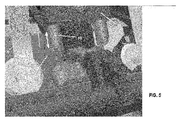
- FIG. 5 shows a second enlarged schematic view of the device 1, in which the two slides 10 of the sliding device shown are extended.
- a sliding device is in each case arranged between two adjacent magazine shafts 4 such that the first of the two slides acts in each case on foil bags 2 of one magazine shaft 4 and the second of the two slides on foil bags 2 of the other magazine shaft.
- an effect of the two takes place Slider 10 on the one foil bag 2 in the right and on the other foil bag 2 in the left upper edge region. Only shortly before the staple / lock case 5 is moved away from its position below the magazine shaft 4, the slider 10 is moved upwards (previously, the transfer arm 6 is still released from the film bag 2).
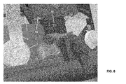
- FIG. 6 3 a third enlarged schematic view of the device 1 is shown, in which the slides 10 are retracted, ie moved upwards, and are received by the housing 11 of the sliding device. After the slides 10 are retracted, the foil bag holders 5 together with the foil bags 2 located therein can be removed from their position below the magazine wells 4.
- FIG. 7 shows a first simplified view of a lateral counter-holder 24 and a magazine shaft 15 in cross section when gripping a foil bag 18 in the magazine shaft 15 by a transfer arm 19 with three suction devices 20.
- a plurality of foil bags 16, 18 are provided, which by means of a holder 17th be positioned in the magazine shaft 15.
- the three suction devices 20 serve for sucking a film bag 18 and thereby for holding the film bag 18, wherein the suction devices 20 suck the film bag 18 at least partially flat, for example by forming a negative pressure.
- a film bag receptacle 23 is arranged to receive and transport a film bag 16, 18.
- the illustrated transfer arm 19 is designed to be rotatable about a horizontal axis 21 and designed to be vertically movable by means of a linkage 22.
- the device comprises at least one counter-holder 24, which is designed to be horizontally movable.
- FIG. 7 is the transfer arm 19 in a tilted position, that is, it is rotated by a certain angular value about the horizontal axis 21 so that it can suck one of the provided in the magazine shaft 15 film bag 18 by means of suction devices 20 and hold or take.
- FIG. 8 shows a second simplified view of the lateral counter-holder 24 and the magazine shaft 15 in cross-section after the foil bag 18 has been brought to the transfer arm 19 in an at least approximately vertical orientation.
- the transfer arm 19 has been rotated around the horizontal axis 21 in such a way, ie by a certain angle value, so that the foil bag 18 grasped by the transfer arm 19 is aligned at least approximately vertically.
- the transfer arm 19 can be moved downwards by means of the linkage 22, ie to the foil bag receptacle positioned below the magazine shaft 15 23, so that the film bag 18 at least partially in the film bag holder 23, such as a staple / lock box, can be introduced.
- the counter-holder 24 has been displaced horizontally, so in a downward process of the transfer arm 19 of these does not come into contact with the anvil 24.
- FIG. 9 shows a third simplified view of the horizontally moved counter-holder 24, the magazine shaft 15 with downwardly moved transfer arm 19 and on the box bottom of a staple / lock box 23 upstanding film bag 18.
- FIG. 10 shows a flowchart of a method for feeding foil bags to a filling machine using a device for feeding foil bags as described above or below.
- step 100 provision is made of foil bags in the magazine shafts of a magazine, wherein a plurality of magazine shafts are arranged in parallel.
- the foil bag receptacles for receiving and transporting the film bags are positioned below the magazine slots in step 101 so that the foil bags provided can be transferred to them.
- step 102 the foil bags are grasped in the magazine shafts by means of transfer arms.
- the gripping can take place by means of a suction device, which is encompassed by the transfer arms, and at least partially sucks the foil bags flat.
- step 103 a downwards movement of the slides takes place.
- step 104 the transfer arms are rotated about a common horizontal axis, thereby moving the foil bags into an at least approximately vertical orientation.
- step 105 After the step 104 of rotation, in step 105, a further downward movement of the transfer arms and at least partial introduction of the foil bags into the foil bag receptacles can take place. After step 105 of the introduction, in step 106, the transfer arms can be released from the foil bags.
- step 107 an upward process of the transfer arms then takes place. Thereafter, in step 108, the slides are retracted. In step 109, the film bag receivers with the film bags therein can then be moved away from their position below the magazine slots by a method.
Abstract
Die Erfindung betrifft eine Vorrichtung zum Zuführen von Folienbeuteln zu einer Füllmaschine mit einem Magazin mit mehreren, parallelen Magazinschächten zum Bereitstellen der Folienbeutel und unterhalb der Magazinschächte positionierbaren Folienbeutelaufnahmen zum Aufnehmen und zum Transportieren der Folienbeutel, wobei jedem Magazinschacht ein Übergabearm zum Ergreifen eines Folienbeutels in dem Magazinschacht und zum Übergeben des ergriffenen Folienbeutels an die unterhalb des Magazinschachts angeordnete Folienbeutelaufnahme zugeordnet ist. Weiter betrifft die Erfindung ein Verfahren zum Zuführen von Folienbeuteln zu einer Füllmaschine mit der Vorrichtung mit den Schritten: Bereitstellen von Folienbeuteln in Magazinschächten eines Magazins, Positionieren von Folienbeutelaufnahmen zum Aufnehmen und Transportieren der Folienbeutel unterhalb der Magazinschächte, Ergreifen der Folienbeutel in den Magazinschächten mittels Übergabearmen und Übergeben der ergriffenen Folienbeutel an die Folienbeutelaufnahmen mittels der Übergabearme.The invention relates to a device for feeding film bags to a filling machine with a magazine having a plurality of parallel magazine shafts for providing the film bag and below the magazine shafts positionable foil bag receptacles for receiving and transporting the foil bag, each magazine slot a transfer arm for gripping a foil bag in the magazine shaft and is assigned for transferring the seized foil bag to the arranged below the magazine slot foil bag receptacle. The invention further relates to a method for feeding foil bags to a filling machine with the device comprising the steps of: providing foil bags in magazine shafts of a magazine, positioning foil bag holders for picking up and transporting the foil bags below the magazine shafts, gripping the foil bags in the magazine shafts by means of transfer arms and Passing the seized foil bag to the foil bag receptacles by means of the transfer arms.
Description
Die Erfindung betrifft eine Vorrichtung zum Zuführen von Folienbeuteln zu einer Füllmaschine gemäß dem Oberbegriff des Anspruchs 1 und ein entsprechendes Verfahren gemäß Anspruch 11.The invention relates to a device for feeding foil bags to a filling machine according to the preamble of claim 1 and to a corresponding method according to
Es ist bekannt, Folienbeutel, die in Magazinschächten eines Magazins bereitgestellt werden, in die Magazinschächte fallen zu lassen, so dass sie durch die Schwerkraft nach unten gezogen werden. Dadurch gelangen die Folienbeutel in unterhalb der Magazinschächte angeordnete Folienbeutelaufnahmen zum Aufnehmen und Weitertransportieren der Folienbeutel. Durch die Verwendung der Schwerkraft für das nach unten Bewegen der Folienbeutel ist nicht immer eine passende Ausrichtung der Folienbeutel in Bezug zu den Folienbeutelaufnahmen gewährleistet, da sich Folienbeutel in einem Magazinschacht drehen oder verkanten können. Auch die Maschinengeschwindigkeit ist begrenzt.It is known to let foil bags, which are provided in magazine shafts of a magazine, fall into the magazine shafts so that they are pulled down by gravity. As a result, the foil bags reach into foil bag receptacles arranged beneath the magazine shafts for picking up and further transporting the foil bags. The use of gravity to move the film bags down does not always ensure proper alignment of the film bags relative to the film bag receivers since film bags can rotate or tilt in a magazine slot. The machine speed is limited.
Die Aufgabe der Erfindung besteht darin, eine Vorrichtung und ein Verfahren zum Zuführen von Folienbeuteln zu einer Füllmaschine zur Verfügung zu stellen, die eine störungsfreie, definierte Übergabe von in Magazinschächten bereitgestellten Folienbeuteln an Folienbeutelaufnahmen auch mit einer hohen Maschinengeschwindigkeit ermöglichen.The object of the invention is to provide an apparatus and a method for feeding foil bags to a filling machine, which enable a trouble-free, defined transfer of foil bags provided in magazine shafts to foil bag receptacles, even at a high machine speed.
Die Aufgabe wird gelöst durch die Vorrichtung nach Anspruch 1 und das Verfahren nach Anspruch 11. Bevorzugte Ausführungsformen und Weiterbildungen sind in den Unteransprüchen offenbart.The object is achieved by the device according to claim 1 and the method according to
Die Vorrichtung zum Zuführen von Folienbeuteln zu einer Füllmaschine umfasst ein Magazin mit mehreren, parallel angeordneten Magazinschächten zum Bereitstellen der Folienbeutel und unterhalb der Magazinschächte positionierbare Folienbeutelaufnahmen zum Aufnehmen und zum Weitertransportieren der aufgenommenen Folienbeutel. Weiter ist jedem Magazinschacht ein Übergabearm zum Ergreifen eines Folienbeutels in dem Magazinschacht und zum Übergeben des ergriffenen Folienbeutels an die unterhalb des Magazinschachts angeordnete Folienbeutelaufnahme zugeordnet.The device for feeding foil bags to a filling machine comprises a magazine having a plurality of magazine shafts arranged in parallel for providing the foil bags and foil bag receivers positionable below the magazine shafts for receiving and transporting the accommodated foil bags. Further, each magazine shaft is assigned a transfer arm for gripping a film bag in the magazine shaft and for transferring the gripped film bag to the film bag receptacle arranged below the magazine shaft.
Durch die Verwendung der Übergabearme ist eine gezielte Übergabe der Folienbeutel an die Folienbeutelaufnahmen möglich, wodurch eine Verdrehung oder Verkantung von Folienbeuteln in den Magazinschächten vermieden werden kann. Somit kann die Vorrichtung auch mit einer hohen Maschinengeschwindigkeit betrieben werden, wobei immer eine gezielte Übergabe der Folienbeutel an die Folienbeutelaufnahmen erfolgt. Das Ergreifen und Übergeben der Folienbeutel mit den Übergabearmen kann als eine Zwangsführung angesehen werden, da dabei zufällige, nicht erwünschte Bewegungen der Folienbeutel unterbunden werden.By using the transfer arms, a targeted transfer of the foil bag to the foil bag receptacles is possible, whereby a twisting or tilting of foil bags can be avoided in the magazine shafts. Thus, the device can also be operated at a high machine speed, whereby a targeted transfer of the foil bag always takes place on the foil bag receptacles. The gripping and transfer of the foil bag with the transfer arms can be regarded as a forced operation, as this random, unwanted movements of the foil bags are prevented.
Die Übergabearme können jeweils mindestens eine Saugvorrichtung zum Ansaugen der Folienbeutel umfassen. Die Saugvorrichtungen ermöglichen ein schonendes Ergreifen der Folienbeutel sowie einen sicheren Transport von den Magazinschächten zu den Folienbeutelaufnahmen. Die Saugvorrichtungen können mit einem oder mehreren Vorrichtungen zum Erzeugen eines Unterdrucks ausgestattet sein. Beispielsweise umfasst ein Übergabearm zwei Saugvorrichtungen mit einem kreisförmigen oder zumindest näherungsweise kreisförmigen Querschnitt, die an einem Folienbeutel symmetrisch angreifen.The transfer arms may each comprise at least one suction device for sucking the film bag. The suction devices enable a gentle gripping of the foil bags as well as a safe transport from the magazine shafts to the foil bag holders. The suction devices may be equipped with one or more negative pressure generating devices. For example, a transfer arm comprises two suction devices with a circular or at least approximately circular cross-section which engage symmetrically on a foil bag.
Jede der Saugvorrichtungen kann dazu ausgelegt sein, einen Folienbeutel zumindest teilweise flächig anzusaugen. Für das Ergreifen und Übergeben der Folienbeutel an die Folienbeutelaufnahmen ist es ausreichend, wenn die Saugvorrichtungen den Folienbeutel nicht komplett ansaugen, sondern nur eine Teilfläche des jeweiligen Folienbeutels angesaugt wird. Durch das nur teilweise flächige Ansaugen ist auch ein nachfolgendes Lösen der Saugvorrichtung vom Folienbeutel einfacher.Each of the suction devices can be designed to suck a film bag at least partially flat. For gripping and transferring the film bag to the film bag receptacles, it is sufficient if the suction devices do not completely suck the film bag, but only a partial surface of the respective film bag is sucked. By only partially flat suction and a subsequent release of the suction device from the foil bag is easier.
Die Übergabearme können um eine gemeinsame horizontale Achse drehbar und mittels eines gemeinsamen Gestänges vertikal verfahrbar ausgelegt sein. Durch die Drehbarkeit der Übergabearme ist es möglich, dass die Folienbeutel in den Magazinschächten ergriffen werden und dann im Magazinschacht in eine Ausrichtung verbracht werden, aus der sie durch ein vertikales Verfahren des Gestänges zumindest teilweise aus dem Magazinschacht entfernt und zumindest teilweise in die Folienbeutelaufnahmen eingebracht werden können. Als Antrieb für das Gestänge zum vertikalen, d.h. nach oben und nach unten, Verfahren kann im oberen Bereich des Gestänges eine Zahnstange mit Antriebsrädern vorgesehen sein.The transfer arms can be designed to be rotatable about a common horizontal axis and to be vertically movable by means of a common linkage. Due to the rotatability of the transfer arms, it is possible for the film bags to be grasped in the magazine shafts and then brought into alignment in the magazine shaft, from which they are at least partially removed from the magazine shaft by a vertical movement of the linkage and at least partially introduced into the film bag receptacles can. As a drive for the linkage to the vertical, i. up and down, method may be provided in the upper region of the linkage a rack with drive wheels.
Zwischen zwei benachbarten Magazinschächten kann eine Schiebevorrichtung angeordnet sein, die mindestens einen Schieber umfasst, der vorzugsweise vertikal verfahrbar ist. Mittels des Schiebers können Folienbeutel innerhalb der Folienbeutelaufnahmen in gewisser Weise an ihrem Platz gehalten werden, ohne dass eine unerwünschte Bewegung nach oben erfolgt, z.B. wenn ein Übergabearm von einem Folienbeutel gelöst bzw. dann nach oben verfahren wird.Between two adjacent magazine shafts, a sliding device may be arranged, which comprises at least one slide, which is preferably movable vertically. By means of the slider, foil pouches within the foil pouches can be held in place to some extent without undesirable upward movement, e.g. when a transfer arm is released from a foil bag or then moved upwards.
Die Schiebevorrichtung kann derart zwischen zwei benachbarten Magazinschächten angeordnet, dass der erste der beiden Schieber jeweils auf Folienbeutel des einen Magazinschachts und der zweite der beiden Schieber jeweils auf Folienbeutel des anderen Magazinschachts einwirken kann. Im Allgemeinen erfolgt eine Einwirkung der Schieber auf einen Folienbeutel daher in den rechten und linken oberen Randbereichen des Folienbeutels.The sliding device can be arranged between two adjacent magazine shafts such that the first of the two slides each on foil bag of a magazine shaft and the second of the two slides can each act on foil bags of the other magazine shaft. In general, an action of the slider on a film bag therefore takes place in the right and left upper edge regions of the film bag.
Ein Übergabespalt kann zwischen dem mindesten einen Schieber und einem Grundkörper des Magazins ausbildbar sein. Der Übergabespalt wird ausgebildet, wenn der mindestens eine Schieber nach unten verfahren ist, wodurch die gezielte Übergabe der Folienbeutel an die Folienbeutelaufnahmen unterstützt werden kann, da eine unerwünschte Bewegung der Folienbeutel unterbunden wird. Die Breite des Übergabespalts ist hierbei vorzugsweise kleiner als 1 mm, jedoch kann diese Breite an den Typ des Folienbeutels angepasst werden.A transfer gap can be formed between the at least one slide and a main body of the magazine. The transfer gap is formed when the at least one slide is moved down, whereby the targeted transfer of the foil bag can be supported on the foil bag receptacles, since unwanted movement of the foil bag is prevented. The width of the transfer gap is preferably less than 1 mm, but this width can be adapted to the type of film bag.
Der mindestens eine Schieber kann eine Labyrinthführung zum Unterbinden einer nach oben Bewegung eines Folienbeutels umfassen. Die Labyrinthführung ist dafür vorgesehen, eine Aufwärtsbewegung eines Folienbeutels zu vermeiden, beispielsweise wenn ein Übergabearm nach dem Lösen von dem Folienbeutel bewegt wird. Beispielsweise kann die Labyrinthführung als ein Vorsprung ausgebildet sein. Da sich die Labyrinthführung bei nach unten gefahrenem Schieber zumindest teilweise in dem Transportweg des von dem Übergabearm ergriffenen und bewegten Folienbeutel befindet, wird beim nach unten Bewegen des Folienbeutels dieser entsprechend bei Kontakt mit der Labyrinthführung in seinen rechten und linken Randbereichen gebogen.The at least one slider may include a labyrinth guide for inhibiting upward movement of a foil bag. The labyrinth guide is intended to prevent upward movement of a foil bag, for example when a transfer arm is moved after release from the foil bag. For example, the labyrinth guide may be formed as a projection. Since the labyrinth guide is at least partially in the transport path of grasped by the transfer arm and moving foil pouch when moving down slide the bag is bent when moving the plastic bag in accordance with this in contact with the labyrinth in its right and left margins.
Die Schiebevorrichtung kann ein Gehäuse umfassen, das den mindestens einen Schieber aufnehmen kann.The pusher may include a housing that can receive the at least one slider.
Die Vorrichtung kann weiter mindestens einen Gegenhalter umfassen, der horizontal verfahrbar ausgelegt ist zum Unterbinden einer nach oben Bewegung eines Folienbeutels. Während ein Folienbeutel durch einen Übergabearm ergriffen und zumindest teilweise in einen Folienbeutelaufnahme eingebracht wird, befindet sich der mindestens eine Gegenhalter vorzugsweise in einer ersten Position außerhalb des Bewegungswegs von Übergabearm und/oder Folienbeutel. Nachdem der Folienbeutel zumindest teilweise in die Folienbeutelaufnahme eingebracht wurde, kann der mindestens eine Gegenhalter horizontal aus der ersten Position in eine zweite Position verfahren werden, so dass der mindestens einen Gegenhalter derart oberhalb des Folienbeutels positioniert ist, dass er ein unerwünschtes nach oben Bewegen des Folienbeutels unterbinden kann, z.B. wenn ein Übergabearm von einem Folienbeutel gelöst bzw. dann nach oben verfahren wird.The device may further comprise at least one counter-holder, which is designed to be horizontally movable to prevent upward movement of a film bag. While a foil bag is gripped by a transfer arm and at least partially inserted into a foil bag receptacle, the at least one counterholder is preferably in a first position outside the path of movement of the transfer arm and / or foil bag. After the film bag has been at least partially introduced into the film bag receptacle, the at least one counter holder can be moved horizontally from the first position to a second position, so that the at least one counter holder is positioned above the film bag such that it undesirably moves upward the film bag can prevent, for example when a transfer arm is released from a foil bag or then moved upwards.
Die Folienbeutelaufnahmen können als Klammer-/Schließkästen ausgebildet sein.The foil bag receptacles can be designed as staple / lock boxes.
Das Verfahren zum Zuführen von Folienbeuteln zu einer Füllmaschine mit einer Vorrichtung wie oben oder weiter unten beschrieben umfasst die Schritte: Bereitstellen von Folienbeuteln in Magazinschächten eines Magazins, Positionieren von Folienbeutelaufnahmen zum Aufnehmen und Transportieren der Folienbeutel unterhalb der Magazinschächte, dann Ergreifen der Folienbeutel in den Magazinschächten mittels Übergabearmen und Übergeben der ergriffenen Folienbeutel an die Folienbeutelaufnahmen mittels der Übergabearme.The method of feeding foil bags to a filling machine with a device as described above or below comprises the steps of providing foil bags in magazine shafts of a magazine, positioning of foil bag receptacles for receiving and transporting the foil bag below the magazine shafts, then gripping the foil bag in the magazine shafts by means of transfer arms and transferring the seized foil bag to the foil bag receptacles by means of the transfer arms.
In jedem der Magazinschächte kann eine bestimmte Anzahl von Folienbeuteln bereitgestellt werden und bevor diese Anzahl von Folienbeuteln verwendet wurde, können weitere Folienbeutel nachgefüllt werden. Da die Folienbeutel von dem Magazin zu einer Füllmaschine verbracht werden sollen, werden unterhalb des Magazins Folienbeutelaufnahmen bereitgestellt. Dabei werden bei einer Anzahl n von parallel angeordneten Magazinschächten n Folienbeutelaufnahmen bereitgestellt, wobei jeweils eine Folienbeutelaufnahme unterhalb eines Magazinschachts positioniert wird. Somit kann ein Folienbeutel eines Magazinschachts an eine Folienbeutelaufnahme übergeben und durch sie dann transportiert werden. Durch das Ergreifen eines Folienbeutels in einem Magazinschacht kann eine geführte Bewegung des Folienbeutels erfolgen, so dass er in einer definierten Weise an die Folienbeutelaufnahme übergeben werden kann.In each of the magazine shafts, a certain number of foil bags can be provided and before this number of foil bags is used, more foil bags can be refilled. Since the film bags are to be moved from the magazine to a filling machine, foil bag receptacles are provided below the magazine. In this case, n foil bag receptacles are provided with a number n of magazine shafts arranged in parallel, wherein in each case a foil bag receptacle is positioned below a magazine shaft. Thus, a foil bag of a magazine shaft can be transferred to a foil bag receptacle and then transported through it. By gripping a foil bag in a magazine shaft, a guided movement of the foil bag can take place, so that it can be transferred to the foil bag receptacle in a defined manner.
Der Schritt des Ergreifens kann ein Ansaugen der Folienbeutel mittels Saugvorrichtungen umfassen, wobei ein Folienbeutel beispielsweise zumindest teilweise flächig angesaugt wird. Durch das nur teilweise flächige Ansaugen ist auch ein nachfolgendes Lösen der Saugvorrichtung vom Folienbeutel einfacher. Die Saugvorrichtungen können ein schonendes Ergreifen der Folienbeutel sowie einen sicheren Transport von den Magazinschächten zu den Folienbeutelaufnahmen ermöglichen. Das Ansaugen kann durch Ausbilden eines Unterdrucks erfolgen.The step of grasping may include suction of the foil pouches by means of suction devices, wherein a foil pouch is sucked, for example, at least partially flat. By only partially flat suction and a subsequent release of the suction device from the foil bag is easier. The suction devices can enable a gentle gripping of the foil bags as well as a safe transport from the magazine shafts to the foil bag receptacles. The suction can be done by forming a negative pressure.
Der Schritt des Übergebens kann weiter den folgenden Schritt umfassen: Drehen der Übergabearme um eine gemeinsame horizontale Achse und dadurch ein Verbringen der Folienbeutel in eine zumindest näherungsweise vertikale Ausrichtung. Aus dieser Ausrichtung heraus können die Folienbeutel an die Folienbeutelaufnahmen übergeben werden. Durch das Drehen um die horizontale Achse können die Übergabearme derart bewegt werden, dass sie die Folienbeutel vom Ort ihres Ergreifens in einem Magazinschacht zumindest teilweise aus dem Magazinschacht heraus bewegen.The handover step may further comprise the step of rotating the transfer arms about a common horizontal axis and thereby moving the foil bags into an at least approximately vertical orientation. From this orientation, the foil bags can be passed to the foil bag receptacles. By rotating about the horizontal axis, the transfer arms can be moved to at least partially move the foil pouches out of the magazine slot from the location of their capture in a magazine slot.
Nach dem Schritt des Ergreifens und vor dem Schritt des Drehens kann ein Ausfahren der Schieber erfolgen. Die ausgefahrenen Schieber sorgen im Weiteren dafür, dass in die Folienbeutelaufnahmen eingebrachte Folienbeutel beim Lösen der Übergabearme von den Folienbeuteln und beim nach oben Verfahren der gelösten Übergabearme keine unerwünschte Bewegung nach oben ausführen.After the step of grasping and before the step of turning, the slides can be extended. Furthermore, the extended slides ensure that foil bags introduced into the foil bag holders do not make any undesired upward movement when releasing the transfer arms from the foil bags and during the upward movement of the dissolved transfer arms.
Nach dem Drehen können weiter die folgenden Schritte erfolgen: nach unten Verfahren der Übergabearme und zumindest teilweises Einbringen der Folienbeutel in die Folienbeutelaufnahmen und nach dem Einbringen Lösen der Saugvorrichtungen von den Folienbeuteln. Bei dem nach unten Verfahren der Übergabearme werden die Folienbeutel auch an den ausgefahrenen Schiebern und deren Labyrinthführung vorbeibewegt. Dabei kommen die Folienbeutel jeweils in Kontakt mit den Labyrinthführungen, so dass ein Folienbeutel in seinen rechten und linken Randbereichen gebogen wird. Wenn ein Folienbeutel in eine Folienbeutelaufnahme eingebracht ist, bei einem Klammer-/Schließkasten beispielsweise auf dessen Kastengrund aufsteht, verhindern die Schieber und die Labyrinthführungen, dass der Folienbeutel eine Bewegung nach oben ausführen kann. Daher kann dann die Saugvorrichtung von dem Folienbeutel gelöst und der Saugarm nach oben verfahren werden.After turning, the following steps may further be carried out: downwards movement of the transfer arms and at least partial introduction of the film bags into the film bag receptacles and after insertion release of the suction devices from the film bags. In the down process of the transfer arms, the foil bags are also moved past the extended slides and their labyrinth guide. In this case, the foil bags each come in contact with the labyrinth guides, so that a foil bag is bent in its right and left edge areas. When a foil bag is inserted into a foil bag receptacle, for example, stands up on its box base in a stapling / closing box, the slides and the labyrinth guides prevent the foil bag from moving upwards. Therefore, the suction device can then be released from the foil bag and the suction arm can be moved upwards.
Nach dem Schritt des Lösens kann ein nach oben Verfahren der Übergabearme erfolgen. Vorzugsweise erfolgt auch ein Drehen der Übergabearme, so dass sich die Übergabearme dann in einer Position in der sie erneut Folienbeutel ergreifen können.After the disengagement step, an upward process of the transfer arms may be performed. Preferably, a rotation of the transfer arms, so that the transfer arms then in a position in which they can again take foil bag.
Nach dem nach oben Verfahren der Übergabearme kann ein nach oben Verfahren der Schieber erfolgen. Nach dem nach oben Verfahren der Schieber kann ein Verfahren der Folienbeutelaufnahmen aus ihrer Position unterhalb der Magazinschächte erfolgen. Die Folienbeutelaufnahmen können dann die Folienbeutel einer Füllmaschine zuführen.After the upward procedure of the transfer arms, an upward procedure of the slide can be done. According to the upward method of the slide, a method of film bag receptacles can be made from their position below the magazine shafts. The foil bag holders can then feed the foil bags to a filling machine.
Die beigefügten Figuren stellen beispielhaft zum besseren Verständnis und zur Veranschaulichung Aspekte der Erfindung dar. Es zeigt:
-
Figur 1 eine erste schematische Ansicht einer Vorrichtung zum Zuführen von Folienbeuteln zu einer Füllmaschine beim Ergreifen von Folienbeuteln in den Magazinschächten durch Übergabearme, -
Figur 2 -
Figur 3 -
Figur 4 eine erste vergrößerte schematische Ansicht der Vorrichtung mit der Labyrinthführung und ausgefahrenen Schiebern, -
Figur 5 -
Figur 6 -
Figur 7 -
Figur 8 -
Figur 9 -
Figur 10
-
FIG. 1 a first schematic view of an apparatus for feeding foil bags to a filling machine when gripping foil bags in the magazine shafts by transfer arms, -
FIG. 2 a second schematic view of the device after the foil bags have been brought with the transfer arms in a vertical orientation, -
FIG. 3 a third schematic view of the device with downwardly moved transfer arms and on the box base upstanding foil bags, -
FIG. 4 a first enlarged schematic view of the device with the labyrinth guide and extended slides, -
FIG. 5 a second enlarged schematic view of the device with extended sliders, -
FIG. 6 a third enlarged schematic view of the device with retracted slides, -
FIG. 7 a first simplified view of a lateral counter-holder and a magazine shaft in cross section when gripping a foil bag in the magazine shaft by a transfer arm with three suction devices, -
FIG. 8 a second simplified view of the lateral counter-holder and the magazine shaft in cross-section after the foil bag has been brought with the transfer arm in a vertical orientation, -
FIG. 9 a third simplified view of the horizontally moved counter-holder, the magazine shaft with downwardly moved transfer arm and on the box base upstanding film bag and -
FIG. 10 a flow chart of a method for feeding foil bags to a filling machine.
Die Abfolge der
In der Darstellung weist jeder der Übergabearme 6 zwei Saugvorrichtungen 7 zum Ansaugen eines Folienbeutels 2 und dadurch zum Halten des Folienbeutels 2 auf, mittels der der Folienbeutel 2 zumindest teilweise flächig angesaugt wird. Die mehreren Übergabearme 6 sind um eine gemeinsame horizontale Achse 8 drehbar und mittels eines gemeinsamen Gestänges 9 vertikal verfahrbar ausgelegt, so dass die Bewegung der Übergabearme 6 in allen Magazinschächten 4 synchron erfolgt.In the illustration, each of the
In
Zudem sind in der Vorrichtung 1 Schiebevorrichtungen vorgesehen, wobei eine Schiebevorrichtung jeweils ein Gehäuse 11 und zwei Schieber 10 umfasst. Die Schieber 10 sind in vertikaler Richtung auf- und abbewegbar ausgebildet. Eine Schiebevorrichtung ist derart zwischen zwei benachbarten Magazinschächten 4 angeordnet, dass der erste der beiden Schieber 10 auf einem Folienbeutel 2 des einen Magazinschachts 4 und der zweite der beiden Schieber 10 auf einem anderen Folienbeutel 2 des anderen, benachbarten Magazinschachts einwirken kann. Im Allgemeinen erfolgt eine Einwirkung der Schieber 10 auf einen Folienbeutel 2 daher in den rechten und linken oberen Randbereichen des Folienbeutels 2.In addition, sliding devices are provided in the device 1, with a sliding device each comprising a
Diese Anordnung der Schiebevorrichtung zwischen benachbarten Magazinschächten 4 ermöglicht eine freie Beweglichkeit der Übergabearme 6 beim Drehen um die gemeinsame horizontale Achse 8.This arrangement of the sliding device between adjacent magazine shafts 4 allows free movement of the
Die beiden äußeren Magazinschächte 4 des Magazins 3, die jeweils nur einen benachbarten Magazinschacht 4 aufweisen, umfassen vorzugsweise auf der Seite ohne benachbarten Magazinschacht eine andersartig ausgeformte Schiebevorrichtung mit einem Gehäuse und nur einem Schieber.The two outer magazine shafts 4 of the
Die Schieber 10 werden aus dem Gehäuse 11 nach unten gefahren, nachdem ein Übergabearm 6 einen Folienbeutel 2 ergriffen und bevor der Übergabearm 6 den Folienbeutel 2 in eine vertikale bzw. annähernd vertikale Ausrichtung gebracht hat. Zwischen dem ausgefahrenen Schieber 10 und einem Grundkörper 14 des Magazins 3 wird dadurch ein Übergabespalt 13 ausgebildet, der vorzugsweise eine Breite von etwa 1 mm oder weniger aufweist.The
Die Schieber 10 umfassen zudem eine Labyrinthführung 12, die hier in Form eines Vorsprungs ausgebildet ist. Die Labyrinthführung 12 verhindert, dass sich ein zum Kastengrund eines Klammer-/Schließkastens geführter Folienbeutel 2 nach oben bewegen kann, z.B. wenn der Übergabearm 6 von dem Folienbeutel 2 gelöst bzw. danach nach oben bewegt wird.The
Da sich die Labyrinthführung 12 bei nach unten gefahrenem Schieber 10 zumindest teilweise in dem Transportweg des von dem Übergabearm 6 ergriffenen und bewegten Folienbeutel 2 befindet, wird beim nach unten Bewegen des Folienbeutels 2 dieser entsprechend in seinen rechten und linken Randbereichen gebogen. Dies stört den Betrieb der Vorrichtung 1 jedoch nicht, da das Material der Folienbeutel 2 eine gewisse Flexibilität aufweist und nach Passieren der Labyrinthführung wieder in die Ausgangsform zurückgeht.Since the
In
Der dargestellte Übergabearm 19 ist um eine horizontale Achse 21 drehbar ausgelegt und mittels eines Gestänges 22 vertikal verfahrbar ausgelegt. Zudem umfasst die Vorrichtung mindestens einen Gegenhalter 24, der horizontal verfahrbar ausgelegt ist.The illustrated
In
Aus der in der
Im Schritt 100 erfolgt ein Bereitstellen von Folienbeuteln in den Magazinschächten eines Magazins, wobei mehrere Magazinschächte parallel angeordnet sind. Die Folienbeutelaufnahmen zum Aufnehmen und Transportieren der Folienbeutel werden im Schritt 101 unterhalb der Magazinschächte positioniert, so dass die bereitgestellten Folienbeutel an sie übergeben werden können. Im Schritt 102 erfolgt ein Ergreifen der Folienbeutel in den Magazinschächten mittels Übergabearmen. Beispielsweise kann das Ergreifen durch eine Saugvorrichtung erfolgen, die von den Übergabearmen umfasst wird, und die Folienbeutel zumindest teilweise flächig ansaugt. Im Schritt 103 erfolgt ein nach unten Verfahren der Schieber. Im Schritt 104 erfolgt ein Drehen der Übergabearme um eine gemeinsame horizontale Achse und dadurch ein Verbringen der Folienbeutel in eine zumindest näherungsweise vertikale Ausrichtung.In step 100, provision is made of foil bags in the magazine shafts of a magazine, wherein a plurality of magazine shafts are arranged in parallel. The foil bag receptacles for receiving and transporting the film bags are positioned below the magazine slots in step 101 so that the foil bags provided can be transferred to them. In step 102, the foil bags are grasped in the magazine shafts by means of transfer arms. For example, the gripping can take place by means of a suction device, which is encompassed by the transfer arms, and at least partially sucks the foil bags flat. In
Nach dem Schritt 104 des Drehens kann im Schritt 105 weiter ein nach unten Verfahren der Übergabearme und ein zumindest teilweises Einbringen der Folienbeutel in die Folienbeutelaufnahmen erfolgen. Nach dem Schritt 105 des Einbringens kann im Schritt 106 ein Lösen der Übergabearme von den Folienbeuteln erfolgen.After the
Im Schritt 107 erfolgt dann ein nach oben Verfahren der Übergabearme. Danach werden im Schritt 108 die Schieber eingefahren. Im Schritt 109 können dann die Folienbeutelaufnahmen mit den darin befindlichen Folienbeuteln aus ihrer Position unterhalb der Magazinschächte durch ein Verfahren wegbewegt werden.In
Claims (18)
dadurch gekennzeichnet, dass
jedem Magazinschacht (4) ein Übergabearm (6) zum Ergreifen eines Folienbeutels (2) in dem Magazinschacht (4) und zum Übergeben des ergriffenen Folienbeutels (2) an die unterhalb des Magazinschachts angeordnete Folienbeutelaufnahme (5) zugeordnet ist.Device (1) for feeding foil bags (2) to a filling machine with a magazine (3) having a plurality of magazine shafts (4) arranged in parallel for providing the foil bags (2) and foil bag receivers (5) which can be positioned underneath the magazine shafts (4) and for further transporting the accommodated foil bags (2)
characterized in that
Each magazine shaft (4) is associated with a transfer arm (6) for gripping a film bag (2) in the magazine shaft (4) and for transferring the gripped film bag (2) to the film bag receptacle (5) arranged below the magazine shaft.
Priority Applications (6)
| Application Number | Priority Date | Filing Date | Title |
|---|---|---|---|
| EP15180156.0A EP3127824B1 (en) | 2015-08-07 | 2015-08-07 | Device and method for feeding film bags to a filling machine |
| ES15180156T ES2719707T3 (en) | 2015-08-07 | 2015-08-07 | Device and procedure for feeding laminated bags to a filling machine |
| US15/750,741 US11220364B2 (en) | 2015-08-07 | 2016-08-05 | Device and method for feeding film bags to a filling machine |
| JP2018506327A JP6806310B2 (en) | 2015-08-07 | 2016-08-05 | Equipment and methods for sending film bags to the filling machine |
| CN201680058304.0A CN108778934B (en) | 2015-08-07 | 2016-08-05 | Apparatus and method for feeding film bags to a filling machine |
| PCT/EP2016/068787 WO2017025474A1 (en) | 2015-08-07 | 2016-08-05 | Device and method for feeding film bags to a filling machine |
Applications Claiming Priority (1)
| Application Number | Priority Date | Filing Date | Title |
|---|---|---|---|
| EP15180156.0A EP3127824B1 (en) | 2015-08-07 | 2015-08-07 | Device and method for feeding film bags to a filling machine |
Publications (2)
| Publication Number | Publication Date |
|---|---|
| EP3127824A1 true EP3127824A1 (en) | 2017-02-08 |
| EP3127824B1 EP3127824B1 (en) | 2019-03-27 |
Family
ID=53969130
Family Applications (1)
| Application Number | Title | Priority Date | Filing Date |
|---|---|---|---|
| EP15180156.0A Expired - Fee Related EP3127824B1 (en) | 2015-08-07 | 2015-08-07 | Device and method for feeding film bags to a filling machine |
Country Status (6)
| Country | Link |
|---|---|
| US (1) | US11220364B2 (en) |
| EP (1) | EP3127824B1 (en) |
| JP (1) | JP6806310B2 (en) |
| CN (1) | CN108778934B (en) |
| ES (1) | ES2719707T3 (en) |
| WO (1) | WO2017025474A1 (en) |
Citations (4)
| Publication number | Priority date | Publication date | Assignee | Title |
|---|---|---|---|---|
| GB694699A (en) * | 1950-10-30 | 1953-07-22 | Hesser Ag Maschf | Improvements relating to apparatus for opening and filling folding bags |
| US3955334A (en) * | 1973-03-30 | 1976-05-11 | Indag Gesellschaft Fur Industrieberdarf | Process and apparatus for supplying pouch-like containers to a filling station |
| DE4035815A1 (en) * | 1990-11-10 | 1992-05-14 | Breitner Abfuellanlagen Gmbh | Liq. filling machine for plastic bags - in which high speed action takes lay flat bags from stack, inflates them with compressed air, fills with liq. and seals off top with weld |
| US5463845A (en) * | 1993-12-10 | 1995-11-07 | General Mills, Inc. | Apparatus for folding, filling, and sealing microwave popcorn bags |
Family Cites Families (18)
| Publication number | Priority date | Publication date | Assignee | Title |
|---|---|---|---|---|
| US2288603A (en) * | 1939-06-13 | 1942-07-07 | Samuel H Berch | Packaging means |
| US3323280A (en) * | 1963-02-19 | 1967-06-06 | Scott & Sons Co O M | Automatic packaging machine |
| US3511395A (en) * | 1968-04-04 | 1970-05-12 | Packaging Ind Inc | Method for handling blisters or the like |
| US4108300A (en) * | 1977-08-10 | 1978-08-22 | Mitsubishi Jukogyo Kabushiki Kaisha | Bag packing apparatus |
| US4473989A (en) * | 1980-10-17 | 1984-10-02 | Toyo Seikan Kaisha, Ltd. | Method, a line and a pouch supporting base for automatically filling up and sealing pouches at high speed |
| JPS57204802A (en) * | 1981-06-02 | 1982-12-15 | Toyo Seikan Kaisha Ltd | High-speed automatic bagging sealing method and its line |
| JP2557481Y2 (en) * | 1990-12-25 | 1997-12-10 | 四国化工機株式会社 | Blank supply device |
| US5480372A (en) * | 1993-12-10 | 1996-01-02 | General Mills, Inc. | Apparatus for folding and loading microwave popcorn bags into a fixture |
| US6880310B2 (en) * | 2002-09-24 | 2005-04-19 | Yakima Packaging Automation, Inc. | Method for automatic bale bag loading |
| US20080110132A1 (en) * | 2006-11-14 | 2008-05-15 | Grupo Bimbo, S.A.B. De C.V. | Automated bags supply system for filling bags with products |
| SI2113463T1 (en) * | 2008-05-02 | 2012-06-29 | Indag Gmbh | Device for handling flexible bags |
| JP6355121B2 (en) * | 2012-12-06 | 2018-07-11 | 株式会社古川製作所 | Large capacity bag feeder |
| CN203199252U (en) * | 2013-02-05 | 2013-09-18 | 广东雅丽洁精细化工有限公司 | Bag taking and conveying device of packing machine |
| JP6040406B2 (en) * | 2013-05-10 | 2016-12-07 | ゼネラルパッカー株式会社 | Gas filling and packaging method and packaging machine |
| JP6286633B2 (en) * | 2013-05-10 | 2018-03-07 | ゼネラルパッカー株式会社 | Packaging bag supply device for packaging machine |
| CN103496466B (en) * | 2013-08-28 | 2015-09-09 | 苏州国衡机电有限公司 | A kind of automatic bag taking, the wrapping machine of feeding, passing on |
| MX2017002665A (en) * | 2014-09-01 | 2017-10-31 | Fillshape S R L | A device and method for feeding pouches to a carousel. |
| US10486884B2 (en) * | 2017-11-30 | 2019-11-26 | JLS Automation | Vacuum packaging apparatus |
-
2015
- 2015-08-07 ES ES15180156T patent/ES2719707T3/en active Active
- 2015-08-07 EP EP15180156.0A patent/EP3127824B1/en not_active Expired - Fee Related
-
2016
- 2016-08-05 CN CN201680058304.0A patent/CN108778934B/en not_active Expired - Fee Related
- 2016-08-05 JP JP2018506327A patent/JP6806310B2/en active Active
- 2016-08-05 WO PCT/EP2016/068787 patent/WO2017025474A1/en active Application Filing
- 2016-08-05 US US15/750,741 patent/US11220364B2/en active Active
Patent Citations (4)
| Publication number | Priority date | Publication date | Assignee | Title |
|---|---|---|---|---|
| GB694699A (en) * | 1950-10-30 | 1953-07-22 | Hesser Ag Maschf | Improvements relating to apparatus for opening and filling folding bags |
| US3955334A (en) * | 1973-03-30 | 1976-05-11 | Indag Gesellschaft Fur Industrieberdarf | Process and apparatus for supplying pouch-like containers to a filling station |
| DE4035815A1 (en) * | 1990-11-10 | 1992-05-14 | Breitner Abfuellanlagen Gmbh | Liq. filling machine for plastic bags - in which high speed action takes lay flat bags from stack, inflates them with compressed air, fills with liq. and seals off top with weld |
| US5463845A (en) * | 1993-12-10 | 1995-11-07 | General Mills, Inc. | Apparatus for folding, filling, and sealing microwave popcorn bags |
Also Published As
| Publication number | Publication date |
|---|---|
| CN108778934B (en) | 2020-10-16 |
| US11220364B2 (en) | 2022-01-11 |
| ES2719707T3 (en) | 2019-07-12 |
| WO2017025474A1 (en) | 2017-02-16 |
| US20190352031A1 (en) | 2019-11-21 |
| EP3127824B1 (en) | 2019-03-27 |
| JP2018525286A (en) | 2018-09-06 |
| JP6806310B2 (en) | 2021-01-06 |
| CN108778934A (en) | 2018-11-09 |
Similar Documents
| Publication | Publication Date | Title |
|---|---|---|
| DE1610467C3 (en) | Method and device for placing the slider and the upper end links on pre-assembled coupled zip fasteners | |
| DE2215093C3 (en) | Device for inserting card corners into corresponding slots in an endless carrier web | |
| CH707362B1 (en) | Method for destacking metal sheets and stacking device. | |
| DE2221039C3 (en) | Device for the automatic attachment of valve bags to the filling spout of a filling device | |
| EP3625778A1 (en) | Filling of boxes for valuable documents | |
| EP3241767A1 (en) | Processing apparatus for film bags | |
| EP1645512B1 (en) | Apparatus for opening of flatly stacked bags | |
| DE3221620A1 (en) | DEVICE FOR ATTACHING COMPONENTS | |
| DE102020111767A1 (en) | Storage and retrieval machine | |
| DE3908957C2 (en) | Method and device for wrapping piece goods with stretch film | |
| EP3127824B1 (en) | Device and method for feeding film bags to a filling machine | |
| WO2002024556A1 (en) | Method and device for supplying regularly objects to a work station | |
| DE1214137B (en) | Device for producing and filling sleeves with a bottom fold on a cigarette packaging machine | |
| EP0332160A2 (en) | Coin stacking device | |
| DE2732080A1 (en) | FEED DEVICE FOR PALLETS AND FLAT MATERIAL | |
| EP3236511A1 (en) | Method and apparatus for the removal of battery cells from a rectangular surrounding | |
| EP3241768B1 (en) | Device for transferring of film bags | |
| AT393641B (en) | Apparatus for bending steel rods to form concrete reinforcing elements | |
| DE102015016749A1 (en) | APPARATUS FOR MANUFACTURING A MEDICAL BAG AND METHOD FOR OPERATING SUCH AN APPROPRIATE APPARATUS | |
| DE2130955C3 (en) | Device for feeding bags or sacks | |
| DE596249C (en) | Feeding device for prismatic folding boxes on packing machines | |
| DE3605932A1 (en) | DEVICE FOR INSERTING COMPONENTS IN PRINTED CIRCUIT BOARDS | |
| DE60119627T2 (en) | Device for picking up tubes from a box and storing them on a conveyor belt | |
| DE657061C (en) | Device for inserting the neck into the bottom part of the box | |
| DE709001C (en) | Device for inserting a sheet under the cover plate of an alignment device |
Legal Events
| Date | Code | Title | Description |
|---|---|---|---|
| PUAI | Public reference made under article 153(3) epc to a published international application that has entered the european phase |
Free format text: ORIGINAL CODE: 0009012 |
|
| STAA | Information on the status of an ep patent application or granted ep patent |
Free format text: STATUS: THE APPLICATION HAS BEEN PUBLISHED |
|
| AK | Designated contracting states |
Kind code of ref document: A1 Designated state(s): AL AT BE BG CH CY CZ DE DK EE ES FI FR GB GR HR HU IE IS IT LI LT LU LV MC MK MT NL NO PL PT RO RS SE SI SK SM TR |
|
| AX | Request for extension of the european patent |
Extension state: BA ME |
|
| STAA | Information on the status of an ep patent application or granted ep patent |
Free format text: STATUS: REQUEST FOR EXAMINATION WAS MADE |
|
| 17P | Request for examination filed |
Effective date: 20170731 |
|
| RBV | Designated contracting states (corrected) |
Designated state(s): AL AT BE BG CH CY CZ DE DK EE ES FI FR GB GR HR HU IE IS IT LI LT LU LV MC MK MT NL NO PL PT RO RS SE SI SK SM TR |
|
| STAA | Information on the status of an ep patent application or granted ep patent |
Free format text: STATUS: EXAMINATION IS IN PROGRESS |
|
| 17Q | First examination report despatched |
Effective date: 20171206 |
|
| GRAP | Despatch of communication of intention to grant a patent |
Free format text: ORIGINAL CODE: EPIDOSNIGR1 |
|
| STAA | Information on the status of an ep patent application or granted ep patent |
Free format text: STATUS: GRANT OF PATENT IS INTENDED |
|
| INTG | Intention to grant announced |
Effective date: 20180612 |
|
| RAP1 | Party data changed (applicant data changed or rights of an application transferred) |
Owner name: INDAG POUCH PARTNERS GMBH |
|
| GRAJ | Information related to disapproval of communication of intention to grant by the applicant or resumption of examination proceedings by the epo deleted |
Free format text: ORIGINAL CODE: EPIDOSDIGR1 |
|
| STAA | Information on the status of an ep patent application or granted ep patent |
Free format text: STATUS: EXAMINATION IS IN PROGRESS |
|
| GRAP | Despatch of communication of intention to grant a patent |
Free format text: ORIGINAL CODE: EPIDOSNIGR1 |
|
| STAA | Information on the status of an ep patent application or granted ep patent |
Free format text: STATUS: GRANT OF PATENT IS INTENDED |
|
| INTC | Intention to grant announced (deleted) | ||
| INTG | Intention to grant announced |
Effective date: 20181023 |
|
| GRAS | Grant fee paid |
Free format text: ORIGINAL CODE: EPIDOSNIGR3 |
|
| GRAA | (expected) grant |
Free format text: ORIGINAL CODE: 0009210 |
|
| STAA | Information on the status of an ep patent application or granted ep patent |
Free format text: STATUS: THE PATENT HAS BEEN GRANTED |
|
| AK | Designated contracting states |
Kind code of ref document: B1 Designated state(s): AL AT BE BG CH CY CZ DE DK EE ES FI FR GB GR HR HU IE IS IT LI LT LU LV MC MK MT NL NO PL PT RO RS SE SI SK SM TR |
|
| REG | Reference to a national code |
Ref country code: GB Ref legal event code: FG4D Free format text: NOT ENGLISH |
|
| REG | Reference to a national code |
Ref country code: CH Ref legal event code: EP |
|
| REG | Reference to a national code |
Ref country code: AT Ref legal event code: REF Ref document number: 1112756 Country of ref document: AT Kind code of ref document: T Effective date: 20190415 |
|
| REG | Reference to a national code |
Ref country code: IE Ref legal event code: FG4D Free format text: LANGUAGE OF EP DOCUMENT: GERMAN |
|
| REG | Reference to a national code |
Ref country code: DE Ref legal event code: R096 Ref document number: 502015008458 Country of ref document: DE |
|
| REG | Reference to a national code |
Ref country code: ES Ref legal event code: FG2A Ref document number: 2719707 Country of ref document: ES Kind code of ref document: T3 Effective date: 20190712 |
|
| PG25 | Lapsed in a contracting state [announced via postgrant information from national office to epo] |
Ref country code: LT Free format text: LAPSE BECAUSE OF FAILURE TO SUBMIT A TRANSLATION OF THE DESCRIPTION OR TO PAY THE FEE WITHIN THE PRESCRIBED TIME-LIMIT Effective date: 20190327 Ref country code: FI Free format text: LAPSE BECAUSE OF FAILURE TO SUBMIT A TRANSLATION OF THE DESCRIPTION OR TO PAY THE FEE WITHIN THE PRESCRIBED TIME-LIMIT Effective date: 20190327 Ref country code: NO Free format text: LAPSE BECAUSE OF FAILURE TO SUBMIT A TRANSLATION OF THE DESCRIPTION OR TO PAY THE FEE WITHIN THE PRESCRIBED TIME-LIMIT Effective date: 20190627 Ref country code: SE Free format text: LAPSE BECAUSE OF FAILURE TO SUBMIT A TRANSLATION OF THE DESCRIPTION OR TO PAY THE FEE WITHIN THE PRESCRIBED TIME-LIMIT Effective date: 20190327 |
|
| REG | Reference to a national code |
Ref country code: NL Ref legal event code: MP Effective date: 20190327 |
|
| PG25 | Lapsed in a contracting state [announced via postgrant information from national office to epo] |
Ref country code: NL Free format text: LAPSE BECAUSE OF FAILURE TO SUBMIT A TRANSLATION OF THE DESCRIPTION OR TO PAY THE FEE WITHIN THE PRESCRIBED TIME-LIMIT Effective date: 20190327 Ref country code: GR Free format text: LAPSE BECAUSE OF FAILURE TO SUBMIT A TRANSLATION OF THE DESCRIPTION OR TO PAY THE FEE WITHIN THE PRESCRIBED TIME-LIMIT Effective date: 20190628 Ref country code: HR Free format text: LAPSE BECAUSE OF FAILURE TO SUBMIT A TRANSLATION OF THE DESCRIPTION OR TO PAY THE FEE WITHIN THE PRESCRIBED TIME-LIMIT Effective date: 20190327 Ref country code: BG Free format text: LAPSE BECAUSE OF FAILURE TO SUBMIT A TRANSLATION OF THE DESCRIPTION OR TO PAY THE FEE WITHIN THE PRESCRIBED TIME-LIMIT Effective date: 20190627 Ref country code: LV Free format text: LAPSE BECAUSE OF FAILURE TO SUBMIT A TRANSLATION OF THE DESCRIPTION OR TO PAY THE FEE WITHIN THE PRESCRIBED TIME-LIMIT Effective date: 20190327 Ref country code: RS Free format text: LAPSE BECAUSE OF FAILURE TO SUBMIT A TRANSLATION OF THE DESCRIPTION OR TO PAY THE FEE WITHIN THE PRESCRIBED TIME-LIMIT Effective date: 20190327 |
|
| PG25 | Lapsed in a contracting state [announced via postgrant information from national office to epo] |
Ref country code: PT Free format text: LAPSE BECAUSE OF FAILURE TO SUBMIT A TRANSLATION OF THE DESCRIPTION OR TO PAY THE FEE WITHIN THE PRESCRIBED TIME-LIMIT Effective date: 20190727 Ref country code: AL Free format text: LAPSE BECAUSE OF FAILURE TO SUBMIT A TRANSLATION OF THE DESCRIPTION OR TO PAY THE FEE WITHIN THE PRESCRIBED TIME-LIMIT Effective date: 20190327 Ref country code: EE Free format text: LAPSE BECAUSE OF FAILURE TO SUBMIT A TRANSLATION OF THE DESCRIPTION OR TO PAY THE FEE WITHIN THE PRESCRIBED TIME-LIMIT Effective date: 20190327 Ref country code: SK Free format text: LAPSE BECAUSE OF FAILURE TO SUBMIT A TRANSLATION OF THE DESCRIPTION OR TO PAY THE FEE WITHIN THE PRESCRIBED TIME-LIMIT Effective date: 20190327 Ref country code: CZ Free format text: LAPSE BECAUSE OF FAILURE TO SUBMIT A TRANSLATION OF THE DESCRIPTION OR TO PAY THE FEE WITHIN THE PRESCRIBED TIME-LIMIT Effective date: 20190327 Ref country code: RO Free format text: LAPSE BECAUSE OF FAILURE TO SUBMIT A TRANSLATION OF THE DESCRIPTION OR TO PAY THE FEE WITHIN THE PRESCRIBED TIME-LIMIT Effective date: 20190327 |
|
| PG25 | Lapsed in a contracting state [announced via postgrant information from national office to epo] |
Ref country code: PL Free format text: LAPSE BECAUSE OF FAILURE TO SUBMIT A TRANSLATION OF THE DESCRIPTION OR TO PAY THE FEE WITHIN THE PRESCRIBED TIME-LIMIT Effective date: 20190327 Ref country code: SM Free format text: LAPSE BECAUSE OF FAILURE TO SUBMIT A TRANSLATION OF THE DESCRIPTION OR TO PAY THE FEE WITHIN THE PRESCRIBED TIME-LIMIT Effective date: 20190327 |
|
| PG25 | Lapsed in a contracting state [announced via postgrant information from national office to epo] |
Ref country code: IS Free format text: LAPSE BECAUSE OF FAILURE TO SUBMIT A TRANSLATION OF THE DESCRIPTION OR TO PAY THE FEE WITHIN THE PRESCRIBED TIME-LIMIT Effective date: 20190727 |
|
| REG | Reference to a national code |
Ref country code: DE Ref legal event code: R097 Ref document number: 502015008458 Country of ref document: DE |
|
| PG25 | Lapsed in a contracting state [announced via postgrant information from national office to epo] |
Ref country code: DK Free format text: LAPSE BECAUSE OF FAILURE TO SUBMIT A TRANSLATION OF THE DESCRIPTION OR TO PAY THE FEE WITHIN THE PRESCRIBED TIME-LIMIT Effective date: 20190327 |
|
| PLBE | No opposition filed within time limit |
Free format text: ORIGINAL CODE: 0009261 |
|
| STAA | Information on the status of an ep patent application or granted ep patent |
Free format text: STATUS: NO OPPOSITION FILED WITHIN TIME LIMIT |
|
| PG25 | Lapsed in a contracting state [announced via postgrant information from national office to epo] |
Ref country code: SI Free format text: LAPSE BECAUSE OF FAILURE TO SUBMIT A TRANSLATION OF THE DESCRIPTION OR TO PAY THE FEE WITHIN THE PRESCRIBED TIME-LIMIT Effective date: 20190327 |
|
| 26N | No opposition filed |
Effective date: 20200103 |
|
| PG25 | Lapsed in a contracting state [announced via postgrant information from national office to epo] |
Ref country code: TR Free format text: LAPSE BECAUSE OF FAILURE TO SUBMIT A TRANSLATION OF THE DESCRIPTION OR TO PAY THE FEE WITHIN THE PRESCRIBED TIME-LIMIT Effective date: 20190327 |
|
| GBPC | Gb: european patent ceased through non-payment of renewal fee |
Effective date: 20190807 |
|
| PG25 | Lapsed in a contracting state [announced via postgrant information from national office to epo] |
Ref country code: MC Free format text: LAPSE BECAUSE OF FAILURE TO SUBMIT A TRANSLATION OF THE DESCRIPTION OR TO PAY THE FEE WITHIN THE PRESCRIBED TIME-LIMIT Effective date: 20190327 Ref country code: LU Free format text: LAPSE BECAUSE OF NON-PAYMENT OF DUE FEES Effective date: 20190807 Ref country code: LI Free format text: LAPSE BECAUSE OF NON-PAYMENT OF DUE FEES Effective date: 20190831 Ref country code: CH Free format text: LAPSE BECAUSE OF NON-PAYMENT OF DUE FEES Effective date: 20190831 |
|
| REG | Reference to a national code |
Ref country code: BE Ref legal event code: MM Effective date: 20190831 |
|
| PG25 | Lapsed in a contracting state [announced via postgrant information from national office to epo] |
Ref country code: IE Free format text: LAPSE BECAUSE OF NON-PAYMENT OF DUE FEES Effective date: 20190807 |
|
| PG25 | Lapsed in a contracting state [announced via postgrant information from national office to epo] |
Ref country code: BE Free format text: LAPSE BECAUSE OF NON-PAYMENT OF DUE FEES Effective date: 20190831 Ref country code: GB Free format text: LAPSE BECAUSE OF NON-PAYMENT OF DUE FEES Effective date: 20190807 |
|
| PG25 | Lapsed in a contracting state [announced via postgrant information from national office to epo] |
Ref country code: CY Free format text: LAPSE BECAUSE OF FAILURE TO SUBMIT A TRANSLATION OF THE DESCRIPTION OR TO PAY THE FEE WITHIN THE PRESCRIBED TIME-LIMIT Effective date: 20190327 |
|
| PG25 | Lapsed in a contracting state [announced via postgrant information from national office to epo] |
Ref country code: HU Free format text: LAPSE BECAUSE OF FAILURE TO SUBMIT A TRANSLATION OF THE DESCRIPTION OR TO PAY THE FEE WITHIN THE PRESCRIBED TIME-LIMIT; INVALID AB INITIO Effective date: 20150807 Ref country code: MT Free format text: LAPSE BECAUSE OF FAILURE TO SUBMIT A TRANSLATION OF THE DESCRIPTION OR TO PAY THE FEE WITHIN THE PRESCRIBED TIME-LIMIT Effective date: 20190327 |
|
| REG | Reference to a national code |
Ref country code: AT Ref legal event code: MM01 Ref document number: 1112756 Country of ref document: AT Kind code of ref document: T Effective date: 20200807 |
|
| PG25 | Lapsed in a contracting state [announced via postgrant information from national office to epo] |
Ref country code: AT Free format text: LAPSE BECAUSE OF NON-PAYMENT OF DUE FEES Effective date: 20200807 |
|
| PGFP | Annual fee paid to national office [announced via postgrant information from national office to epo] |
Ref country code: FR Payment date: 20210820 Year of fee payment: 7 Ref country code: IT Payment date: 20210831 Year of fee payment: 7 |
|
| PGFP | Annual fee paid to national office [announced via postgrant information from national office to epo] |
Ref country code: ES Payment date: 20210901 Year of fee payment: 7 Ref country code: DE Payment date: 20210826 Year of fee payment: 7 |
|
| PG25 | Lapsed in a contracting state [announced via postgrant information from national office to epo] |
Ref country code: MK Free format text: LAPSE BECAUSE OF FAILURE TO SUBMIT A TRANSLATION OF THE DESCRIPTION OR TO PAY THE FEE WITHIN THE PRESCRIBED TIME-LIMIT Effective date: 20190327 |
|
| REG | Reference to a national code |
Ref country code: DE Ref legal event code: R119 Ref document number: 502015008458 Country of ref document: DE |
|
| PG25 | Lapsed in a contracting state [announced via postgrant information from national office to epo] |
Ref country code: IT Free format text: LAPSE BECAUSE OF NON-PAYMENT OF DUE FEES Effective date: 20220807 Ref country code: FR Free format text: LAPSE BECAUSE OF NON-PAYMENT OF DUE FEES Effective date: 20220831 Ref country code: DE Free format text: LAPSE BECAUSE OF NON-PAYMENT OF DUE FEES Effective date: 20230301 |
|
| REG | Reference to a national code |
Ref country code: ES Ref legal event code: FD2A Effective date: 20230927 |
|
| PG25 | Lapsed in a contracting state [announced via postgrant information from national office to epo] |
Ref country code: ES Free format text: LAPSE BECAUSE OF NON-PAYMENT OF DUE FEES Effective date: 20220808 |