EP3127814A1 - Aircraft heating assembly with liquid cooled internal combustion engine and heating element using waste heat - Google Patents
Aircraft heating assembly with liquid cooled internal combustion engine and heating element using waste heat Download PDFInfo
- Publication number
- EP3127814A1 EP3127814A1 EP16183273.8A EP16183273A EP3127814A1 EP 3127814 A1 EP3127814 A1 EP 3127814A1 EP 16183273 A EP16183273 A EP 16183273A EP 3127814 A1 EP3127814 A1 EP 3127814A1
- Authority
- EP
- European Patent Office
- Prior art keywords
- coolant
- engine
- aircraft
- heating element
- circulation path
- Prior art date
- Legal status (The legal status is an assumption and is not a legal conclusion. Google has not performed a legal analysis and makes no representation as to the accuracy of the status listed.)
- Granted
Links
Images

Classifications
-
- B—PERFORMING OPERATIONS; TRANSPORTING
- B64—AIRCRAFT; AVIATION; COSMONAUTICS
- B64D—EQUIPMENT FOR FITTING IN OR TO AIRCRAFT; FLIGHT SUITS; PARACHUTES; ARRANGEMENT OR MOUNTING OF POWER PLANTS OR PROPULSION TRANSMISSIONS IN AIRCRAFT
- B64D33/00—Arrangement in aircraft of power plant parts or auxiliaries not otherwise provided for
- B64D33/08—Arrangement in aircraft of power plant parts or auxiliaries not otherwise provided for of power plant cooling systems
-
- B—PERFORMING OPERATIONS; TRANSPORTING
- B64—AIRCRAFT; AVIATION; COSMONAUTICS
- B64D—EQUIPMENT FOR FITTING IN OR TO AIRCRAFT; FLIGHT SUITS; PARACHUTES; ARRANGEMENT OR MOUNTING OF POWER PLANTS OR PROPULSION TRANSMISSIONS IN AIRCRAFT
- B64D33/00—Arrangement in aircraft of power plant parts or auxiliaries not otherwise provided for
- B64D33/08—Arrangement in aircraft of power plant parts or auxiliaries not otherwise provided for of power plant cooling systems
- B64D33/10—Radiator arrangement
-
- B—PERFORMING OPERATIONS; TRANSPORTING
- B64—AIRCRAFT; AVIATION; COSMONAUTICS
- B64D—EQUIPMENT FOR FITTING IN OR TO AIRCRAFT; FLIGHT SUITS; PARACHUTES; ARRANGEMENT OR MOUNTING OF POWER PLANTS OR PROPULSION TRANSMISSIONS IN AIRCRAFT
- B64D15/00—De-icing or preventing icing on exterior surfaces of aircraft
- B64D15/02—De-icing or preventing icing on exterior surfaces of aircraft by ducted hot gas or liquid
- B64D15/06—Liquid application
-
- B—PERFORMING OPERATIONS; TRANSPORTING
- B64—AIRCRAFT; AVIATION; COSMONAUTICS
- B64D—EQUIPMENT FOR FITTING IN OR TO AIRCRAFT; FLIGHT SUITS; PARACHUTES; ARRANGEMENT OR MOUNTING OF POWER PLANTS OR PROPULSION TRANSMISSIONS IN AIRCRAFT
- B64D41/00—Power installations for auxiliary purposes
-
- B—PERFORMING OPERATIONS; TRANSPORTING
- B64—AIRCRAFT; AVIATION; COSMONAUTICS
- B64F—GROUND OR AIRCRAFT-CARRIER-DECK INSTALLATIONS SPECIALLY ADAPTED FOR USE IN CONNECTION WITH AIRCRAFT; DESIGNING, MANUFACTURING, ASSEMBLING, CLEANING, MAINTAINING OR REPAIRING AIRCRAFT, NOT OTHERWISE PROVIDED FOR; HANDLING, TRANSPORTING, TESTING OR INSPECTING AIRCRAFT COMPONENTS, NOT OTHERWISE PROVIDED FOR
- B64F5/00—Designing, manufacturing, assembling, cleaning, maintaining or repairing aircraft, not otherwise provided for; Handling, transporting, testing or inspecting aircraft components, not otherwise provided for
- B64F5/20—Ground installations for de-icing aircraft
-
- F—MECHANICAL ENGINEERING; LIGHTING; HEATING; WEAPONS; BLASTING
- F01—MACHINES OR ENGINES IN GENERAL; ENGINE PLANTS IN GENERAL; STEAM ENGINES
- F01P—COOLING OF MACHINES OR ENGINES IN GENERAL; COOLING OF INTERNAL-COMBUSTION ENGINES
- F01P3/00—Liquid cooling
- F01P3/20—Cooling circuits not specific to a single part of engine or machine
-
- F—MECHANICAL ENGINEERING; LIGHTING; HEATING; WEAPONS; BLASTING
- F01—MACHINES OR ENGINES IN GENERAL; ENGINE PLANTS IN GENERAL; STEAM ENGINES
- F01P—COOLING OF MACHINES OR ENGINES IN GENERAL; COOLING OF INTERNAL-COMBUSTION ENGINES
- F01P7/00—Controlling of coolant flow
- F01P7/14—Controlling of coolant flow the coolant being liquid
- F01P7/16—Controlling of coolant flow the coolant being liquid by thermostatic control
-
- B—PERFORMING OPERATIONS; TRANSPORTING
- B64—AIRCRAFT; AVIATION; COSMONAUTICS
- B64D—EQUIPMENT FOR FITTING IN OR TO AIRCRAFT; FLIGHT SUITS; PARACHUTES; ARRANGEMENT OR MOUNTING OF POWER PLANTS OR PROPULSION TRANSMISSIONS IN AIRCRAFT
- B64D33/00—Arrangement in aircraft of power plant parts or auxiliaries not otherwise provided for
- B64D33/02—Arrangement in aircraft of power plant parts or auxiliaries not otherwise provided for of combustion air intakes
- B64D2033/0213—Arrangement in aircraft of power plant parts or auxiliaries not otherwise provided for of combustion air intakes specially adapted for auxiliary power units (APU's)
-
- B—PERFORMING OPERATIONS; TRANSPORTING
- B64—AIRCRAFT; AVIATION; COSMONAUTICS
- B64D—EQUIPMENT FOR FITTING IN OR TO AIRCRAFT; FLIGHT SUITS; PARACHUTES; ARRANGEMENT OR MOUNTING OF POWER PLANTS OR PROPULSION TRANSMISSIONS IN AIRCRAFT
- B64D33/00—Arrangement in aircraft of power plant parts or auxiliaries not otherwise provided for
- B64D33/02—Arrangement in aircraft of power plant parts or auxiliaries not otherwise provided for of combustion air intakes
- B64D2033/0233—Arrangement in aircraft of power plant parts or auxiliaries not otherwise provided for of combustion air intakes comprising de-icing means
-
- F—MECHANICAL ENGINEERING; LIGHTING; HEATING; WEAPONS; BLASTING
- F01—MACHINES OR ENGINES IN GENERAL; ENGINE PLANTS IN GENERAL; STEAM ENGINES
- F01P—COOLING OF MACHINES OR ENGINES IN GENERAL; COOLING OF INTERNAL-COMBUSTION ENGINES
- F01P2025/00—Measuring
- F01P2025/08—Temperature
-
- F—MECHANICAL ENGINEERING; LIGHTING; HEATING; WEAPONS; BLASTING
- F01—MACHINES OR ENGINES IN GENERAL; ENGINE PLANTS IN GENERAL; STEAM ENGINES
- F01P—COOLING OF MACHINES OR ENGINES IN GENERAL; COOLING OF INTERNAL-COMBUSTION ENGINES
- F01P2050/00—Applications
- F01P2050/20—Aircraft engines
-
- F—MECHANICAL ENGINEERING; LIGHTING; HEATING; WEAPONS; BLASTING
- F01—MACHINES OR ENGINES IN GENERAL; ENGINE PLANTS IN GENERAL; STEAM ENGINES
- F01P—COOLING OF MACHINES OR ENGINES IN GENERAL; COOLING OF INTERNAL-COMBUSTION ENGINES
- F01P2060/00—Cooling circuits using auxiliaries
- F01P2060/18—Heater
-
- F—MECHANICAL ENGINEERING; LIGHTING; HEATING; WEAPONS; BLASTING
- F05—INDEXING SCHEMES RELATING TO ENGINES OR PUMPS IN VARIOUS SUBCLASSES OF CLASSES F01-F04
- F05D—INDEXING SCHEME FOR ASPECTS RELATING TO NON-POSITIVE-DISPLACEMENT MACHINES OR ENGINES, GAS-TURBINES OR JET-PROPULSION PLANTS
- F05D2220/00—Application
- F05D2220/50—Application for auxiliary power units (APU's)
-
- F—MECHANICAL ENGINEERING; LIGHTING; HEATING; WEAPONS; BLASTING
- F05—INDEXING SCHEMES RELATING TO ENGINES OR PUMPS IN VARIOUS SUBCLASSES OF CLASSES F01-F04
- F05D—INDEXING SCHEME FOR ASPECTS RELATING TO NON-POSITIVE-DISPLACEMENT MACHINES OR ENGINES, GAS-TURBINES OR JET-PROPULSION PLANTS
- F05D2260/00—Function
- F05D2260/20—Heat transfer, e.g. cooling
- F05D2260/213—Heat transfer, e.g. cooling by the provision of a heat exchanger within the cooling circuit
-
- Y—GENERAL TAGGING OF NEW TECHNOLOGICAL DEVELOPMENTS; GENERAL TAGGING OF CROSS-SECTIONAL TECHNOLOGIES SPANNING OVER SEVERAL SECTIONS OF THE IPC; TECHNICAL SUBJECTS COVERED BY FORMER USPC CROSS-REFERENCE ART COLLECTIONS [XRACs] AND DIGESTS
- Y02—TECHNOLOGIES OR APPLICATIONS FOR MITIGATION OR ADAPTATION AGAINST CLIMATE CHANGE
- Y02P—CLIMATE CHANGE MITIGATION TECHNOLOGIES IN THE PRODUCTION OR PROCESSING OF GOODS
- Y02P70/00—Climate change mitigation technologies in the production process for final industrial or consumer products
- Y02P70/50—Manufacturing or production processes characterised by the final manufactured product
-
- Y—GENERAL TAGGING OF NEW TECHNOLOGICAL DEVELOPMENTS; GENERAL TAGGING OF CROSS-SECTIONAL TECHNOLOGIES SPANNING OVER SEVERAL SECTIONS OF THE IPC; TECHNICAL SUBJECTS COVERED BY FORMER USPC CROSS-REFERENCE ART COLLECTIONS [XRACs] AND DIGESTS
- Y02—TECHNOLOGIES OR APPLICATIONS FOR MITIGATION OR ADAPTATION AGAINST CLIMATE CHANGE
- Y02T—CLIMATE CHANGE MITIGATION TECHNOLOGIES RELATED TO TRANSPORTATION
- Y02T10/00—Road transport of goods or passengers
- Y02T10/10—Internal combustion engine [ICE] based vehicles
- Y02T10/12—Improving ICE efficiencies
-
- Y—GENERAL TAGGING OF NEW TECHNOLOGICAL DEVELOPMENTS; GENERAL TAGGING OF CROSS-SECTIONAL TECHNOLOGIES SPANNING OVER SEVERAL SECTIONS OF THE IPC; TECHNICAL SUBJECTS COVERED BY FORMER USPC CROSS-REFERENCE ART COLLECTIONS [XRACs] AND DIGESTS
- Y02—TECHNOLOGIES OR APPLICATIONS FOR MITIGATION OR ADAPTATION AGAINST CLIMATE CHANGE
- Y02T—CLIMATE CHANGE MITIGATION TECHNOLOGIES RELATED TO TRANSPORTATION
- Y02T50/00—Aeronautics or air transport
- Y02T50/60—Efficient propulsion technologies, e.g. for aircraft
Definitions
- the application relates generally to liquid cooled internal combustion engines and, more particularly, to the use of waste heat from engine assemblies including such engines.
- a known way to avoid or minimize icing problems in APU inlets includes designing the APU turbo-machinery to be capable of ingesting the ice without damage. However, such design may not be possible in all types of APU engines.
- De-icing in other surfaces of the engine and the aircraft, pre-heating of oil and fuel, and generation of heat for cabin use is often provided by electrical elements using main aircraft power or power generated by the APU.
- the power required by such systems reduces the power available for other uses and/or increases the required size of the APU, and accordingly its weight and cost.
- an aircraft heating assembly comprising: an internal combustion engine having a liquid coolant system distinct from any fuel and lubricating system of the engine, the liquid cooling system including cooling passages in the internal combustion engine for circulating a liquid coolant from a coolant inlet to a coolant outlet; a coolant circulation path outside of the internal combustion engine, the coolant circulation path in fluid communication with the coolant inlet and the coolant outlet, the coolant circulation path extending through a heat exchanger configured to remove a portion of a waste heat from the liquid coolant; and a heating element in heat exchange relationship with the coolant circulation path to receive another portion of the waste heat therefrom, the heating element in heat exchange relationship with a portion of the aircraft to be heated.
- a method of heating a portion of an aircraft comprising: removing waste heat from an internal combustion engine of an auxiliary power unit of the aircraft with a dedicated liquid coolant distinct from any fuel and lubricating system of the auxiliary power unit; transferring at least part of the waste heat from the liquid coolant circulated out of the internal combustion engine to a heating element in heat exchange relationship with the portion of the aircraft; and heating the portion of the aircraft with the heating element.
- a compound engine assembly 10 which in a particular embodiment is used as an auxiliary power unit (APU) is generally shown.
- the compound engine assembly 10 generally includes a supercharger compressor 20 compressing the air to feed an engine core 12' including one or more intermittent internal combustion engines 12.
- the supercharger compressor 20 may also provide bleed air for the aircraft, or an additional compressor 21 may be provided for that use.
- the exhaust from the engine core 12' is fed to one or more turbines 26, 22 of a compounding turbine section.
- the compressor(s) 20, 21 may be driven by the turbines 26, 22 and/or the engine core 12'.
- the compressor(s) 20, 21 is/are driven by the engine core 12' through a transmission 19; in another particular embodiment, the compressor(s) 20, 21 is/are driven by the turbines 26, 22, for example by being coupled to the same shaft or being engaged to the turbine shaft through a transmission.
- One or more of the turbines 26, 22 is/are configured to compound power with the engine core 12'; in the embodiment shown, the turbine and engine shafts are coupled through a transmission provided by a gearbox 28.
- the internal combustion engine(s) 12 are rotary intermittent internal combustion engine, for example Wankel engines; it is however understood that other types of liquid-cooled internal combustion engines, or other types of heat producing engines may alternately be used.
- FIG. 2 an example of a Wankel engine which may be used in the engine core 12' is shown. It is understood that the configuration of the engine(s) 12, e.g. placement of ports, number and placement of seals, etc., may vary from that of the embodiment shown.
- the engine 12 comprises a housing 32 defining a rotor cavity having a profile defining two lobes, which is preferably an epitrochoid.
- a rotor 34 is received within the rotor cavity.
- the rotor defines three circumferentially-spaced apex portions 36, and a generally triangular profile with outwardly arched sides.
- the apex portions 36 are in sealing engagement with the inner surface of a peripheral wall 38 of the housing 32 to form and separate three working chambers 40 of variable volume between the rotor 34 and the housing 32.
- the peripheral wall 38 extends between two axially spaced apart end walls 54 to enclose the rotor cavity.
- the rotor 34 is engaged to an eccentric portion 42 of an output shaft 16 to perform orbital revolutions within the rotor cavity.
- the output shaft 16 performs three rotations for each orbital revolution of the rotor 34.
- the geometrical axis 44 of the rotor 34 is offset from and parallel to the axis 46 of the housing 32.
- each chamber 40 varies in volume and moves around the rotor cavity to undergo the four phases of intake, compression, expansion and exhaust.
- An intake port 48 is provided through the peripheral wall 38 for admitting compressed air into one of the working chambers 40.
- An exhaust port 50 is also provided through the peripheral wall 38 for discharge of the exhaust gases from the working chambers 40.
- Passages 52 for a spark plug, glow plug or other ignition mechanism, as well as for one or more fuel injectors of a fuel injection system are also provided through the peripheral wall 38.
- the intake port 48, the exhaust port 50 and/or the passages 52 may be provided through the end or side wall 54 of the housing.
- a subchamber (not shown) may be provided in communication with the chambers 40, for pilot or pre injection of fuel for combustion.
- the working chambers 40 are sealed by spring-loaded peripheral or apex seals 56 extending from the rotor 34 to engage the inner surface of the peripheral wall 38, and spring-loaded face or gas seals 58 and end or corner seals 60 extending from the rotor 34 to engage the inner surface of the end walls 54.
- the rotor 34 also includes at least one spring-loaded oil seal ring 62 biased against the inner surface of the end wall 54 around the bearing for the rotor 34 on the shaft eccentric portion 42.
- the fuel injector(s) of the engine 12 which in a particular embodiment are common rail fuel injectors, communicate with a source 30 (see Fig. 1 ) of Heavy fuel (e.g. diesel, kerosene (jet fuel), equivalent biofuel), and deliver the heavy fuel into the engine 12 such that the combustion chamber is stratified with a rich fuel-air mixture near the ignition source and a leaner mixture elsewhere.
- Heavy fuel e.g. diesel, kerosene (jet fuel), equivalent biofuel
- An aircraft heating assembly includes a coolant system for the engine(s) 12 of the engine core 12', which in a particular embodiment is distinct from any fuel and lubricating system of the engine(s) 12 and of the auxiliary power unit 10 as a whole.
- a dedicated coolant is circulated through the engine(s) 12 of the engine core 12', through a plurality of cooling passages 64 defined in the walls of the housing 32, and this dedicated coolant is circulated separately and independently from the lubricant and the fuel of the auxiliary power unit 10, including the lubricant of the engine core 12'.
- the dedicated liquid coolant may be for example water, or water mixed with anti-freeze liquid(s) such as ethylene glycol.
- the cooling passages 64 are in fluid communication with a coolant inlet 66 and a coolant outlet 68 of the engine core 12', whether directly or through communication with one or more other cooling passages 64.
- a coolant circulation path 70 is defined outside of the engine(s) 12, in fluid communication with the coolant inlet 66 and the coolant outlet 68.
- the coolant circulation path 70 extends through a heat exchanger 72 configured to remove waste heat from the coolant.
- waste heat refers to the heat from the heated coolant circulated out of the engine core 12', which needs to be removed before the coolant is recirculated to the engine core 12' to perform its cooling function, or to any other type of waste heat produced by the heat producing engine(s) of the engine core 12'.
- the coolant cooling system including the coolant circulation path 70 provides an opportunity to transfer heat to useful locations using the "used" coolant as a medium.
- the aircraft heating assembly accordingly includes one or more heating elements 76, 76' in heat exchange relationship with the coolant circulation path 70, and in heat exchange relationship with a portion 8 of the aircraft to be heated.
- a configuration for the engine assembly 10 and aircraft heating assembly according to a particular embodiment is shown, where the engine assembly 10 is an auxiliary power unit (APU) and the waste heat is used to prevent or limit ice formation in the inlet 14 of the engine assembly 10.
- the heating elements 76 are in heat exchange relationship with the coolant circulation path 70 by being in fluid communication therewith, and the portion 8 of the aircraft to be heated includes multiple surfaces in the air inlet communicating with the compressor 20.
- the hot coolant from the engine(s) 12 is circulated directly through fluid passages forming the liquid heating elements 76, each positioned in heat exchange relationship with a relevant inlet surface to prevent or limit ice formation when the engine assembly 10 is running.
- the coolant is returned to the coolant circulation path 70 at reduced temperature.
- any other heating element such as in the exemplary heating element locations shown at 76', is also in fluid communication with the coolant circulation path 70.
- Exemplary locations for the heating elements 76, 76' and accordingly portion(s) 8 of the aircraft to be heated include, but are not limited to, the inlet door 78, the inlet duct surfaces 80, flow turning devices 82 (e.g. splitters, acoustic panels), compressor variable inlet guide vanes 84, and/or confined areas 86 existing within the inlet where the geometry may be conducive to ice accretion.
- the engine core 12' is used to rotate a fan 74 driving a cooling airflow through the heat exchanger 72.
- a suitable flow driving element e.g. pump
- a bypass conduit 88 provides a fluid communication between a portion of the coolant circulation path 70 upstream of the heat exchanger 72 and a portion of the coolant circulation path 70 downstream of the heat exchanger 72.
- the bypass conduit 88 includes a valve 90 modulated by a thermostat, which accordingly regulates the temperature of the coolant by selectively bypassing the heat exchanger 72.
- the bypass system is designed to fail safe such that the engine cooling circuit is not compromised by a failure of the bypass valve 90; this could include, for example, the capability to detect low heating system back pressure (indicating leakage) and closing off the system if it falls, and/or designing the bypass system to most probably fail in the non-bypassing mode (full flow to the heat exchanger 72).
- a configuration for the engine assembly 10 is shown, where the engine assembly 10 is an auxiliary power unit (APU) and the waste heat is used to provide thermal anti-icing (or augment the capability of existing anti icing systems) in tail-plane aerodynamic surfaces 90.
- the heating elements 76 are thus defined by fluid passages under key tail-plane aerodynamic surfaces 90, through which the heated coolant from the coolant circulation path 70 is circulated. After performing its heating function the coolant is returned to the coolant circulation path 70 at reduced temperature.
- the coolant circulation path 70 extends through the heat exchanger 72 such as shown in Fig. 1 .
- this embodiment may have the advantage of keeping part of the aircraft ice free in cold weather between flights. This may reduce or eliminate the need for fluid de-icing prior to departure.
- heating elements 76 are shown as extending in a horizontal tail-plane in close proximity to the APU, alternately the heating elements 76 could be placed under any aircraft surface requiring to be heated in cold weather, particularly while the APU is running.
- Fig. 4b shows a variation of the embodiment of Fig. 4a , where the heating element 76 is in heat exchange relationship with the coolant circulation path 70 being in fluid communication with a fluid circulation path 92, defined separately from the coolant circulation path 70 and receiving waste heat from the coolant circulation path 70.
- the fluid (e.g. liquid) circulating through the fluid circulation path 92 and through the heating elements 76 may have the same or a different composition than the coolant circulating through the coolant circulation path 70, but both circulate independently, i.e. without being in fluid communication with one another.
- the fluid circulation path 92 and coolant circulation path 70 are in heat exchange relationship with one another through a heat exchanger 94 (e.g. liquid to liquid heat exchanger).
- such a configuration allows for improved segregation between the two systems, so that a failure of the aerodynamic surface heating fluid circuit does not necessarily critically impair the function of the APU.
- a separate circulating pump system 96 is used for the fluid circulating through the fluid circulation path 92.
- the coolant circulation path 70 extends through the heat exchanger 72 such as shown in Fig. 1 .
- the separate fluid circulation path 92 with heat exchanger 94 can also be used in an inlet de-icing system such as shown in Fig. 3 to circulate a separate fluid through the heating elements 76, 76'.
- FIG. 5 a configuration for the engine assembly 10 and aircraft heating assembly according to another particular embodiment is shown, where the engine assembly 10 is an auxiliary power unit (APU) and the waste heat is used to provide thermal anti-icing in an aerodynamic surface 98 (in the tail or elsewhere).
- the heating element 76 is defined by a fluid passage under the aerodynamic surface 98.
- the heating element 76 is in fluid communication with the fluid circulation path 92 defined separately from the coolant circulation path 70 and in heat exchange relationship therewith through the heat exchanger 94; it is understood that alternately, the heating element 76 may be in fluid communication with the coolant circulation path 70 so that the coolant from the engine core 12' is circulated directly therethrough.
- one or more electrical heating element(s) 100 is/are in heat exchange relationship with the heating element(s) 76.
- the temperature of the fluid circulating through the heating element 76 is boosted by the electrical heating elements 100, operating from the power produced by a generator 104 driven by the engine core 12' (as shown) or from the aircraft power supply.
- These boost electrical heating elements 100 could be local to the anti-icing site.
- the warm fluid engine liquid coolant or separate fluid
- the wing leading edge area where its temperature is locally boosted by the electrical heating elements 100 before entering the heating element(s) 76.
- Such a system could provide a measure of bi-energy capability and be operable using either the waste heat from the engine core 12', electrical power in combination with waste heat, or electrical power alone (with the aid of an auxiliary circulating pump when the liquid coolant of the engine core 12' is used).
- the heating element(s) 100 is/are controlled by a de-icing temperature controller 102 according to the requirements for de-icing and the waste heat temperature available from the engine core 12'.
- the return temperature to the engine core 12' may be controlled by modulating or cycling the electrical heating element 100 so that the thermal capacity of the coolant heat exchanger 72 (see Fig. 1 ) is not exceeded.
- the temperature of the fluid circulating through the heating element 76 may be additionally or alternately boosted using the waste heat generated by the cooling and/or lubricating oil used to cool and/or lubricate other elements of the engine core 12' and/or of the engine assembly 10.
- the waste heat from the engine core 12' can thus be used, for example through circulating the coolant of the engine core 12' or a fluid in heat exchange therewith through heating elements 76, 76' at various locations, to provide heat for de-icing or icing prevention in a portion 8 of the aircraft including any one of or in any combination of: engine inlet (e.g. APU inlet), inlet door, inlet splitter, inlet plenum, variable inlet guide vanes, tailplane surfaces, airfoil surfaces (with or without assist from local electrical heating elements), etc., for example as set forth above.
- engine inlet e.g. APU inlet
- inlet door e.g. APU inlet
- inlet splitter e.g., inlet plenum
- variable inlet guide vanes e.g., tailplane surfaces
- tailplane surfaces e.g., airfoil surfaces (with or without assist from local electrical heating elements), etc.
- the portion 8 of the aircraft to be heated can include engine oil and/or engine fuel: the heating elements 76, 76' can be used to provide engine oil warming and/or fuel heating for other engines in reasonable proximity to the engine assembly 10.
- the waste heat from the APU may be used for engine oil pre-heating in extreme climates. Engine starting drag rises at very cold extreme temperatures due to high oil viscosity.
- the APU waste heat may be used to pre-warm the engine oil for the prime mover engine(s) or the nacelle. This may be more easily, although not exclusively, arranged for rear fuselage mounted engines where the nacelles would be in relatively close proximity to the APU.
- the APU waste heat may also or alternately be used for fuel pre-heating and/or fuel icing prevention.
- the portion 8 of the aircraft to be heated can include a ram air inlet, so as to provide ram air pre-heating.
- the portion 8 of the aircraft to be heated can include air and/or water in a passenger cabin: the heating elements 76, 76' can be used as a source of heat for cabin use such as hot water (heating element in heat exchange relationship with water source), or cabin heating in cold weather ((heating element in heat exchange relationship with air source), for example using waste heat from the APU.
- the heating elements 76, 76' can be used as a source of heat for cabin use such as hot water (heating element in heat exchange relationship with water source), or cabin heating in cold weather ((heating element in heat exchange relationship with air source), for example using waste heat from the APU.
- the portion 8 of the aircraft to be heated can include electronic or electrical equipment: the heating elements 76, 76' can be used as a source of heat for electronic or electrical equipment which must start rapidly in cold conditions, including batteries. Electronic equipment can suffer delayed start up in cold conditions. Electronic equipment in the vicinity of the APU can be heated by waste heat from the APU coolant cooling system. This can also be applied to electrical batteries, the performance of which may drop rapidly at low temperatures.
- the portion 8 of the aircraft (which may include portions of the auxiliary power unit 10) is heated in accordance with the following. Waste heat is removed from the internal combustion engine(s) 12 of the auxiliary power unit 10 with the dedicated liquid coolant distinct from any fuel and lubricating system of the auxiliary power unit 10. At least part of the waste heat is transferred from the liquid coolant circulated out of the engine(s) 12 to the heating element(s) 76, 76' in heat exchange relationship with the portion 8 of the aircraft, and the portion 8 of the aircraft with is heated the heating element(s) 76, 76'.
- transferring the waste heat to the heating element 76, 76' may include circulating the liquid coolant through the heating element 76, 76' or circulating an additional fluid in heat exchange relationship with the liquid coolant to transfer the waste heat to the additional fluid, and circulating the additional fluid through the heating element 76, 76'. Also, in a particular embodiment, only part of the waste heat is transferred from the liquid coolant to the heating element 76, 76', and a remaining part of the waste heat is removed from the liquid coolant through heat exchange with a cooling air flow. The portion of the liquid coolant circulated in heat exchange relationship with the cooling air flow may be modulated.
- the heating element(s) 76, 76' may be heated by an additional heat source separate from the waste heat of the liquid coolant (for example electrical heating elements 100 and/or waste heat from other systems, e.g. lubrication system).
- the portion 8 of the aircraft heated with the heating element(s) 76, 76' may be any one or any combination of a surface susceptible to icing, one or more element(s) of the air inlet communicating with the internal combustion engine(s) 12 (e.g. inlet door, inlet duct surface, flow splitter, acoustic panel, inlet plenum, variable inlet guide vanes), a tailplane surface, an airfoil surface, engine oil, engine fuel, the main engine ram air inlet, air in the passenger cabin, water in the passenger cabin, and electronic or electrical equipment (e.g. battery).
- a surface susceptible to icing e.g. inlet door, inlet duct surface, flow splitter, acoustic panel, inlet plenum, variable inlet guide vanes
- a tailplane surface e.g. inlet door, inlet duct surface, flow splitter, acoustic panel, inlet plenum, variable inlet guide vanes
- a tailplane surface
- the engine assembly 10 is shown as a turbo compound engine assembly 10, it is understood that it could alternately be a non-supercharged engine assembly and/or an engine assembly with an engine core including one or more liquid cooled reciprocating engine(s) with similar heat balance.
- the heating element(s) 76, 76' can be used to recycle waste heat of a liquid cooled engine used without a compressor and/or without turbines.
- the engine assembly 10 with an internal combustion engine core 12' (e.g. rotary engine core), with its constant volume combustion cycle, has a waste heat breakdown different from a pure gas turbine engine. Less heat is evacuated through the exhaust and more heat is given up to the engine casing resulting in a need for a core engine cooling system. With a liquid cooling mechanism being employed there is also opportunity to transport significant amounts of waste heat to areas of the aircraft where it may be useful with low pumping energy cost. In this way the need for cooling provisions on the engine (e.g. APU) installation itself can be reduced and the demand on expensive sources of energy such as main engine bleed and main electrical power can be reduced.
- an internal combustion engine core 12' e.g. rotary engine core
- the engine core 12' can alternately include any other similar engine with a closed combustion volume resulting in a similar heat balance, including, but not limited to, reciprocating engine(s).
Landscapes
- Engineering & Computer Science (AREA)
- Aviation & Aerospace Engineering (AREA)
- Mechanical Engineering (AREA)
- Chemical & Material Sciences (AREA)
- Combustion & Propulsion (AREA)
- General Engineering & Computer Science (AREA)
- Manufacturing & Machinery (AREA)
- Transportation (AREA)
- Structures Of Non-Positive Displacement Pumps (AREA)
- Engine Equipment That Uses Special Cycles (AREA)
Abstract
Description
- The application relates generally to liquid cooled internal combustion engines and, more particularly, to the use of waste heat from engine assemblies including such engines.
- A known way to avoid or minimize icing problems in APU inlets includes designing the APU turbo-machinery to be capable of ingesting the ice without damage. However, such design may not be possible in all types of APU engines.
- De-icing in other surfaces of the engine and the aircraft, pre-heating of oil and fuel, and generation of heat for cabin use is often provided by electrical elements using main aircraft power or power generated by the APU. The power required by such systems reduces the power available for other uses and/or increases the required size of the APU, and accordingly its weight and cost.
- In one aspect, there is provided an aircraft heating assembly comprising: an internal combustion engine having a liquid coolant system distinct from any fuel and lubricating system of the engine, the liquid cooling system including cooling passages in the internal combustion engine for circulating a liquid coolant from a coolant inlet to a coolant outlet; a coolant circulation path outside of the internal combustion engine, the coolant circulation path in fluid communication with the coolant inlet and the coolant outlet, the coolant circulation path extending through a heat exchanger configured to remove a portion of a waste heat from the liquid coolant; and a heating element in heat exchange relationship with the coolant circulation path to receive another portion of the waste heat therefrom, the heating element in heat exchange relationship with a portion of the aircraft to be heated.
- In another aspect, there is provided a method of heating a portion of an aircraft, the method comprising: removing waste heat from an internal combustion engine of an auxiliary power unit of the aircraft with a dedicated liquid coolant distinct from any fuel and lubricating system of the auxiliary power unit; transferring at least part of the waste heat from the liquid coolant circulated out of the internal combustion engine to a heating element in heat exchange relationship with the portion of the aircraft; and heating the portion of the aircraft with the heating element.
- Reference is now made to the accompanying figures in which:
-
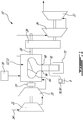
Fig. 1 is a diagram of an engine assembly in accordance with a particular embodiment; -
Fig. 2 is a schematic cross-sectional view of a rotary engine which can be used on the engine assembly ofFig. 1 ; -
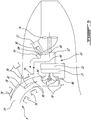
Fig. 3 is a schematic cross-sectional view of an engine assembly such asFig. 1 , used as an auxiliary power unit (APU) and including inlet heating elements, in accordance with a particular embodiment; -
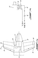
Fig. 4a is a schematic cross-sectional view of an engine assembly such asFig. 1 , used as an auxiliary power unit (APU) and including tailplane heating elements, in accordance with another particular embodiment; -
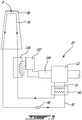
Fig. 4b is a schematic cross-sectional view of part of an engine assembly such as shown inFig. 4a with a fluid circulation system in accordance with another particular embodiment; and -
Fig. 5 is a schematic cross-sectional view of an engine assembly such asFig. 1 , used as an auxiliary power unit (APU) and including aircraft heating elements, in accordance with another particular embodiment. - Referring to
Fig. 1 , acompound engine assembly 10 which in a particular embodiment is used as an auxiliary power unit (APU) is generally shown. Thecompound engine assembly 10 generally includes asupercharger compressor 20 compressing the air to feed an engine core 12' including one or more intermittentinternal combustion engines 12. Thesupercharger compressor 20 may also provide bleed air for the aircraft, or anadditional compressor 21 may be provided for that use. The exhaust from the engine core 12' is fed to one ormore turbines turbines transmission 19; in another particular embodiment, the compressor(s) 20, 21 is/are driven by theturbines turbines gearbox 28. - In a particular embodiment, the internal combustion engine(s) 12 are rotary intermittent internal combustion engine, for example Wankel engines; it is however understood that other types of liquid-cooled internal combustion engines, or other types of heat producing engines may alternately be used.
- Referring to
Fig. 2 , an example of a Wankel engine which may be used in the engine core 12' is shown. It is understood that the configuration of the engine(s) 12, e.g. placement of ports, number and placement of seals, etc., may vary from that of the embodiment shown. - The
engine 12 comprises ahousing 32 defining a rotor cavity having a profile defining two lobes, which is preferably an epitrochoid. Arotor 34 is received within the rotor cavity. The rotor defines three circumferentially-spacedapex portions 36, and a generally triangular profile with outwardly arched sides. Theapex portions 36 are in sealing engagement with the inner surface of aperipheral wall 38 of thehousing 32 to form and separate threeworking chambers 40 of variable volume between therotor 34 and thehousing 32. Theperipheral wall 38 extends between two axially spaced apartend walls 54 to enclose the rotor cavity. - The
rotor 34 is engaged to aneccentric portion 42 of anoutput shaft 16 to perform orbital revolutions within the rotor cavity. Theoutput shaft 16 performs three rotations for each orbital revolution of therotor 34. Thegeometrical axis 44 of therotor 34 is offset from and parallel to theaxis 46 of thehousing 32. During each orbital revolution, eachchamber 40 varies in volume and moves around the rotor cavity to undergo the four phases of intake, compression, expansion and exhaust. - An
intake port 48 is provided through theperipheral wall 38 for admitting compressed air into one of theworking chambers 40. Anexhaust port 50 is also provided through theperipheral wall 38 for discharge of the exhaust gases from theworking chambers 40.Passages 52 for a spark plug, glow plug or other ignition mechanism, as well as for one or more fuel injectors of a fuel injection system (not shown inFig. 1 ) are also provided through theperipheral wall 38. Alternately, theintake port 48, theexhaust port 50 and/or thepassages 52 may be provided through the end orside wall 54 of the housing. A subchamber (not shown) may be provided in communication with thechambers 40, for pilot or pre injection of fuel for combustion. - For efficient operation the
working chambers 40 are sealed by spring-loaded peripheral orapex seals 56 extending from therotor 34 to engage the inner surface of theperipheral wall 38, and spring-loaded face orgas seals 58 and end orcorner seals 60 extending from therotor 34 to engage the inner surface of theend walls 54. Therotor 34 also includes at least one spring-loadedoil seal ring 62 biased against the inner surface of theend wall 54 around the bearing for therotor 34 on the shafteccentric portion 42. - The fuel injector(s) of the
engine 12, which in a particular embodiment are common rail fuel injectors, communicate with a source 30 (seeFig. 1 ) of Heavy fuel (e.g. diesel, kerosene (jet fuel), equivalent biofuel), and deliver the heavy fuel into theengine 12 such that the combustion chamber is stratified with a rich fuel-air mixture near the ignition source and a leaner mixture elsewhere. - Referring back to
Fig. 1 , the engine core 12' is liquid cooled. An aircraft heating assembly includes a coolant system for the engine(s) 12 of the engine core 12', which in a particular embodiment is distinct from any fuel and lubricating system of the engine(s) 12 and of theauxiliary power unit 10 as a whole. In other words, a dedicated coolant is circulated through the engine(s) 12 of the engine core 12', through a plurality ofcooling passages 64 defined in the walls of thehousing 32, and this dedicated coolant is circulated separately and independently from the lubricant and the fuel of theauxiliary power unit 10, including the lubricant of the engine core 12'. The dedicated liquid coolant may be for example water, or water mixed with anti-freeze liquid(s) such as ethylene glycol. Thecooling passages 64 are in fluid communication with acoolant inlet 66 and acoolant outlet 68 of the engine core 12', whether directly or through communication with one or moreother cooling passages 64. Acoolant circulation path 70 is defined outside of the engine(s) 12, in fluid communication with thecoolant inlet 66 and thecoolant outlet 68. Thecoolant circulation path 70 extends through aheat exchanger 72 configured to remove waste heat from the coolant. The term "waste heat" as used herein refers to the heat from the heated coolant circulated out of the engine core 12', which needs to be removed before the coolant is recirculated to the engine core 12' to perform its cooling function, or to any other type of waste heat produced by the heat producing engine(s) of the engine core 12'. The coolant cooling system including thecoolant circulation path 70 provides an opportunity to transfer heat to useful locations using the "used" coolant as a medium. The aircraft heating assembly accordingly includes one ormore heating elements 76, 76' in heat exchange relationship with thecoolant circulation path 70, and in heat exchange relationship with aportion 8 of the aircraft to be heated. - Referring to
Fig. 3 , a configuration for theengine assembly 10 and aircraft heating assembly according to a particular embodiment is shown, where theengine assembly 10 is an auxiliary power unit (APU) and the waste heat is used to prevent or limit ice formation in theinlet 14 of theengine assembly 10. In this embodiment, theheating elements 76 are in heat exchange relationship with thecoolant circulation path 70 by being in fluid communication therewith, and theportion 8 of the aircraft to be heated includes multiple surfaces in the air inlet communicating with thecompressor 20. The hot coolant from the engine(s) 12 is circulated directly through fluid passages forming theliquid heating elements 76, each positioned in heat exchange relationship with a relevant inlet surface to prevent or limit ice formation when theengine assembly 10 is running. After performing this heating function, the coolant is returned to thecoolant circulation path 70 at reduced temperature. Although the fluid communication between only one of theheating elements 76 and thecoolant circulation path 70 is illustrated, it is understood that any other heating element, such as in the exemplary heating element locations shown at 76', is also in fluid communication with thecoolant circulation path 70. Exemplary locations for theheating elements 76, 76' and accordingly portion(s) 8 of the aircraft to be heated include, but are not limited to, theinlet door 78, theinlet duct surfaces 80, flow turning devices 82 (e.g. splitters, acoustic panels), compressor variableinlet guide vanes 84, and/or confinedareas 86 existing within the inlet where the geometry may be conducive to ice accretion. - The engine core 12' is used to rotate a
fan 74 driving a cooling airflow through theheat exchanger 72. Although not shown, a suitable flow driving element (e.g. pump) is provided in fluid communication with thecoolant circulation path 70 to drive the circulation of the coolant therethrough and through thecooling passages 64. A bypass conduit 88 provides a fluid communication between a portion of thecoolant circulation path 70 upstream of theheat exchanger 72 and a portion of thecoolant circulation path 70 downstream of theheat exchanger 72. The bypass conduit 88 includes avalve 90 modulated by a thermostat, which accordingly regulates the temperature of the coolant by selectively bypassing theheat exchanger 72. In a particular embodiment, the bypass system is designed to fail safe such that the engine cooling circuit is not compromised by a failure of thebypass valve 90; this could include, for example, the capability to detect low heating system back pressure (indicating leakage) and closing off the system if it falls, and/or designing the bypass system to most probably fail in the non-bypassing mode (full flow to the heat exchanger 72). - Most APU installations are in the tail-plane area. In the embodiment shown in Referring to
Fig. 4a , a configuration for theengine assembly 10 according to another particular embodiment is shown, where theengine assembly 10 is an auxiliary power unit (APU) and the waste heat is used to provide thermal anti-icing (or augment the capability of existing anti icing systems) in tail-plane aerodynamic surfaces 90. Theheating elements 76 are thus defined by fluid passages under key tail-planeaerodynamic surfaces 90, through which the heated coolant from thecoolant circulation path 70 is circulated. After performing its heating function the coolant is returned to thecoolant circulation path 70 at reduced temperature. Although not shown inFig. 4a , thecoolant circulation path 70 extends through theheat exchanger 72 such as shown inFig. 1 . - Since the APU may be run on the ground, this embodiment may have the advantage of keeping part of the aircraft ice free in cold weather between flights. This may reduce or eliminate the need for fluid de-icing prior to departure.
- It is understood that although the
heating elements 76 are shown as extending in a horizontal tail-plane in close proximity to the APU, alternately theheating elements 76 could be placed under any aircraft surface requiring to be heated in cold weather, particularly while the APU is running. -
Fig. 4b shows a variation of the embodiment ofFig. 4a , where theheating element 76 is in heat exchange relationship with thecoolant circulation path 70 being in fluid communication with afluid circulation path 92, defined separately from thecoolant circulation path 70 and receiving waste heat from thecoolant circulation path 70. The fluid (e.g. liquid) circulating through thefluid circulation path 92 and through theheating elements 76 may have the same or a different composition than the coolant circulating through thecoolant circulation path 70, but both circulate independently, i.e. without being in fluid communication with one another. Thefluid circulation path 92 andcoolant circulation path 70 are in heat exchange relationship with one another through a heat exchanger 94 (e.g. liquid to liquid heat exchanger). In a particular embodiment, such a configuration allows for improved segregation between the two systems, so that a failure of the aerodynamic surface heating fluid circuit does not necessarily critically impair the function of the APU. A separate circulatingpump system 96 is used for the fluid circulating through thefluid circulation path 92. Although not shown inFig. 4b , thecoolant circulation path 70 extends through theheat exchanger 72 such as shown inFig. 1 . - It is understood that the separate
fluid circulation path 92 withheat exchanger 94 can also be used in an inlet de-icing system such as shown inFig. 3 to circulate a separate fluid through theheating elements 76, 76'. - In a larger aircraft the APU waste heat may be not be sufficient to provide adequate heat for de-icing. Referring to
Fig. 5 , a configuration for theengine assembly 10 and aircraft heating assembly according to another particular embodiment is shown, where theengine assembly 10 is an auxiliary power unit (APU) and the waste heat is used to provide thermal anti-icing in an aerodynamic surface 98 (in the tail or elsewhere). Here again, theheating element 76 is defined by a fluid passage under theaerodynamic surface 98. In the embodiment shown, theheating element 76 is in fluid communication with thefluid circulation path 92 defined separately from thecoolant circulation path 70 and in heat exchange relationship therewith through theheat exchanger 94; it is understood that alternately, theheating element 76 may be in fluid communication with thecoolant circulation path 70 so that the coolant from the engine core 12' is circulated directly therethrough. - In this embodiment, one or more electrical heating element(s) 100 is/are in heat exchange relationship with the heating element(s) 76. For example, the temperature of the fluid circulating through the
heating element 76 is boosted by theelectrical heating elements 100, operating from the power produced by agenerator 104 driven by the engine core 12' (as shown) or from the aircraft power supply. These boostelectrical heating elements 100 could be local to the anti-icing site. For example, the warm fluid (engine liquid coolant or separate fluid) is pumped to the wing leading edge area, where its temperature is locally boosted by theelectrical heating elements 100 before entering the heating element(s) 76. Furthermore such a system could provide a measure of bi-energy capability and be operable using either the waste heat from the engine core 12', electrical power in combination with waste heat, or electrical power alone (with the aid of an auxiliary circulating pump when the liquid coolant of the engine core 12' is used). The heating element(s) 100 is/are controlled by ade-icing temperature controller 102 according to the requirements for de-icing and the waste heat temperature available from the engine core 12'. The return temperature to the engine core 12' may be controlled by modulating or cycling theelectrical heating element 100 so that the thermal capacity of the coolant heat exchanger 72 (seeFig. 1 ) is not exceeded. - Although not shown, the temperature of the fluid circulating through the
heating element 76 may be additionally or alternately boosted using the waste heat generated by the cooling and/or lubricating oil used to cool and/or lubricate other elements of the engine core 12' and/or of theengine assembly 10. - In a particular embodiment, the waste heat from the engine core 12' can thus be used, for example through circulating the coolant of the engine core 12' or a fluid in heat exchange therewith through
heating elements 76, 76' at various locations, to provide heat for de-icing or icing prevention in aportion 8 of the aircraft including any one of or in any combination of: engine inlet (e.g. APU inlet), inlet door, inlet splitter, inlet plenum, variable inlet guide vanes, tailplane surfaces, airfoil surfaces (with or without assist from local electrical heating elements), etc., for example as set forth above. - In addition or in the alternative, the
portion 8 of the aircraft to be heated can include engine oil and/or engine fuel: theheating elements 76, 76' can be used to provide engine oil warming and/or fuel heating for other engines in reasonable proximity to theengine assembly 10. For example, the waste heat from the APU may be used for engine oil pre-heating in extreme climates. Engine starting drag rises at very cold extreme temperatures due to high oil viscosity. The APU waste heat may be used to pre-warm the engine oil for the prime mover engine(s) or the nacelle. This may be more easily, although not exclusively, arranged for rear fuselage mounted engines where the nacelles would be in relatively close proximity to the APU. The APU waste heat may also or alternately be used for fuel pre-heating and/or fuel icing prevention. Theportion 8 of the aircraft to be heated can include a ram air inlet, so as to provide ram air pre-heating. - In addition or in the alternative, the
portion 8 of the aircraft to be heated can include air and/or water in a passenger cabin: theheating elements 76, 76' can be used as a source of heat for cabin use such as hot water (heating element in heat exchange relationship with water source), or cabin heating in cold weather ((heating element in heat exchange relationship with air source), for example using waste heat from the APU. - In addition or in the alternative, the
portion 8 of the aircraft to be heated can include electronic or electrical equipment: theheating elements 76, 76' can be used as a source of heat for electronic or electrical equipment which must start rapidly in cold conditions, including batteries. Electronic equipment can suffer delayed start up in cold conditions. Electronic equipment in the vicinity of the APU can be heated by waste heat from the APU coolant cooling system. This can also be applied to electrical batteries, the performance of which may drop rapidly at low temperatures. - Accordingly, in a particular embodiment, the
portion 8 of the aircraft (which may include portions of the auxiliary power unit 10) is heated in accordance with the following. Waste heat is removed from the internal combustion engine(s) 12 of theauxiliary power unit 10 with the dedicated liquid coolant distinct from any fuel and lubricating system of theauxiliary power unit 10. At least part of the waste heat is transferred from the liquid coolant circulated out of the engine(s) 12 to the heating element(s) 76, 76' in heat exchange relationship with theportion 8 of the aircraft, and theportion 8 of the aircraft with is heated the heating element(s) 76, 76'. - As detailed above, transferring the waste heat to the
heating element 76, 76' may include circulating the liquid coolant through theheating element 76, 76' or circulating an additional fluid in heat exchange relationship with the liquid coolant to transfer the waste heat to the additional fluid, and circulating the additional fluid through theheating element 76, 76'. Also, in a particular embodiment, only part of the waste heat is transferred from the liquid coolant to theheating element 76, 76', and a remaining part of the waste heat is removed from the liquid coolant through heat exchange with a cooling air flow. The portion of the liquid coolant circulated in heat exchange relationship with the cooling air flow may be modulated. The heating element(s) 76, 76' may be heated by an additional heat source separate from the waste heat of the liquid coolant (for exampleelectrical heating elements 100 and/or waste heat from other systems, e.g. lubrication system). - As detailed above, the
portion 8 of the aircraft heated with the heating element(s) 76, 76' may be any one or any combination of a surface susceptible to icing, one or more element(s) of the air inlet communicating with the internal combustion engine(s) 12 (e.g. inlet door, inlet duct surface, flow splitter, acoustic panel, inlet plenum, variable inlet guide vanes), a tailplane surface, an airfoil surface, engine oil, engine fuel, the main engine ram air inlet, air in the passenger cabin, water in the passenger cabin, and electronic or electrical equipment (e.g. battery). - Although the
engine assembly 10 is shown as a turbocompound engine assembly 10, it is understood that it could alternately be a non-supercharged engine assembly and/or an engine assembly with an engine core including one or more liquid cooled reciprocating engine(s) with similar heat balance. For example, the heating element(s) 76, 76' can be used to recycle waste heat of a liquid cooled engine used without a compressor and/or without turbines. - In a particular embodiment, the
engine assembly 10 with an internal combustion engine core 12' (e.g. rotary engine core), with its constant volume combustion cycle, has a waste heat breakdown different from a pure gas turbine engine. Less heat is evacuated through the exhaust and more heat is given up to the engine casing resulting in a need for a core engine cooling system. With a liquid cooling mechanism being employed there is also opportunity to transport significant amounts of waste heat to areas of the aircraft where it may be useful with low pumping energy cost. In this way the need for cooling provisions on the engine (e.g. APU) installation itself can be reduced and the demand on expensive sources of energy such as main engine bleed and main electrical power can be reduced. - It is understood that the engine core 12' can alternately include any other similar engine with a closed combustion volume resulting in a similar heat balance, including, but not limited to, reciprocating engine(s).
- The above description is meant to be exemplary only, and one skilled in the art will recognize that changes may be made to the embodiments described without departing from the scope of the invention disclosed. Modifications which fall within the scope of the present invention will be apparent to those skilled in the art, in light of a review of this disclosure, and such modifications are intended to fall within the appended claims.
Claims (15)
- An aircraft heating assembly comprising:an internal combustion engine having a liquid coolant system distinct from any fuel and lubricating system of the engine, the liquid cooling system including cooling passages in the internal combustion engine for circulating a liquid coolant from a coolant inlet to a coolant outlet;a coolant circulation path outside of the internal combustion engine, the coolant circulation path in fluid communication with the coolant inlet and the coolant outlet, the coolant circulation path extending through a heat exchanger configured to remove a portion of a waste heat from the liquid coolant; anda heating element in heat exchange relationship with the coolant circulation path to receive another portion of the waste heat therefrom, the heating element in heat exchange relationship with a portion of the aircraft to be heated.
- The assembly as defined in claim 1, wherein:the heating element is in heat exchange relationship with the coolant circulation path through fluid communication with the coolant circulation path; orthe heating element is in heat exchange relationship with the coolant circulation path through fluid communication with an additional fluid circulation path, the additional fluid circulation path in heat exchange relationship with the coolant circulation path through an additional heat exchanger.
- The assembly as defined in claim 1 or 2, further comprising a bypass conduit providing fluid communication between a portion of the coolant circulation path upstream of the heat exchanger and a portion of the coolant circulation path downstream of the heat exchanger, the bypass conduit including a valve modulated by a thermostat.
- The assembly as defined in any preceding claim, further comprising an electrical heating element in heat exchange relationship with the heating element.
- The assembly as defined in any preceding claim, further comprising at least one additional heating element in fluid communication with the heating element.
- The assembly as defined in any preceding claim, wherein the portion of the aircraft to be heated includes:a surface susceptible to icing;at least one element of an air inlet communicating with the internal combustion engine, optionally wherein the at least one element is selected from the group consisting of: inlet door, inlet duct surface, flow splitter, acoustic panel, inlet plenum, and variable inlet guide vanes;a tailplane surface;an airfoil surface;engine oil;engine fuel;a ram air inlet for a main engine of the aircraft;air in a passenger cabin of the aircraft;water in a passenger cabin of the aircraft; and/orelectronic or electrical equipment.
- The assembly as defined in any preceding claim, wherein the internal combustion engine is a Wankel rotary engine including a rotor having three apex portions mounted for eccentric revolutions within an internal cavity defined in a housing, the internal cavity having an epitrochoid shape with two lobes, the cooling passages being defined through the housing.
- The assembly as defined in any preceding claim, further comprising a compressor in fluid communication with an air inlet of the engine core, and a turbine in fluid communication with an exhaust of the engine core, the turbine compounded with the engine core.
- A method of heating a portion of an aircraft, the method comprising:removing waste heat from an internal combustion engine of an auxiliary power unit of the aircraft with a dedicated liquid coolant distinct from any fuel and lubricating system of the auxiliary power unit;transferring at least part of the waste heat from the liquid coolant circulated out of the internal combustion engine to a heating element in heat exchange relationship with the portion of the aircraft; andheating the portion of the aircraft with the heating element.
- The method as defined in claim 9, wherein transferring the at least part of the waste heat to the heating element includes:circulating the liquid coolant through the heating element, orcirculating an additional fluid in heat exchange relationship with the liquid coolant to transfer the at least part of the waste heat to the additional fluid, and circulating the additional fluid through the heating element.
- The method as defined in claim 9 or 10, wherein only part of the waste heat is transferred from the liquid coolant to the heating element, a remaining part of the waste heat being removed from the liquid coolant through heat exchange with a cooling air flow.
- The method as defined in claim 11, further comprising modulating a portion of the liquid coolant circulated in heat exchange relationship with the cooling air flow.
- The method as defined in any of claims 9 to 12, further comprising providing additional heat to the heating element using a heat source separate from the waste heat.
- The method as defined in any of claims 9 to 13, wherein the internal combustion engine is a Wankel rotary engine including a rotor having three apex portions mounted for eccentric revolutions within an internal cavity defined in the housing, the internal cavity having an epitrochoid shape with two lobes.
- The method as defined in any of claims 9 to 14, wherein the portion of the aircraft to be heated includes:a surface susceptible to icing;at least one element of an air inlet communicating with the internal combustion engine, optionally wherein the at least one element is selected from the group consisting of: inlet door, inlet duct surface, flow splitter, acoustic panel, inlet plenum, and variable inlet guide vanes;a tailplane surface;an airfoil surface;engine oil;engine fuel;a ram air inlet for a main engine of the aircraft;air in a passenger cabin of the aircraft;water in a passenger cabin of the aircraft; and/orelectronic or electrical equipment.
Priority Applications (1)
| Application Number | Priority Date | Filing Date | Title |
|---|---|---|---|
| PL16183273T PL3127814T3 (en) | 2015-08-07 | 2016-08-08 | Aircraft heating assembly with liquid cooled internal combustion engine and heating element using waste heat |
Applications Claiming Priority (2)
| Application Number | Priority Date | Filing Date | Title |
|---|---|---|---|
| US201562202287P | 2015-08-07 | 2015-08-07 | |
| US15/227,501 US11214381B2 (en) | 2015-08-07 | 2016-08-03 | Aircraft heating assembly with liquid cooled internal combustion engine and heating element using waste heat |
Publications (2)
| Publication Number | Publication Date |
|---|---|
| EP3127814A1 true EP3127814A1 (en) | 2017-02-08 |
| EP3127814B1 EP3127814B1 (en) | 2020-07-15 |
Family
ID=56852070
Family Applications (1)
| Application Number | Title | Priority Date | Filing Date |
|---|---|---|---|
| EP16183273.8A Active EP3127814B1 (en) | 2015-08-07 | 2016-08-08 | Aircraft heating assembly with liquid cooled internal combustion engine and heating element using waste heat |
Country Status (7)
| Country | Link |
|---|---|
| US (1) | US11214381B2 (en) |
| EP (1) | EP3127814B1 (en) |
| CN (1) | CN108137163B (en) |
| CA (1) | CA2938113C (en) |
| ES (1) | ES2814100T3 (en) |
| PL (1) | PL3127814T3 (en) |
| WO (1) | WO2017024392A1 (en) |
Cited By (6)
| Publication number | Priority date | Publication date | Assignee | Title |
|---|---|---|---|---|
| EP3409590A1 (en) * | 2017-06-02 | 2018-12-05 | Airbus Operations, S.L. | Aircraft with a bleed air heating system for apu compartment |
| IT201900005586A1 (en) * | 2019-04-11 | 2019-04-11 | ||
| EP3647205A1 (en) * | 2018-10-29 | 2020-05-06 | Pratt & Whitney Canada Corp. | Method and system for cooling an auxiliary power unit using aircraft fuel |
| EP3747766A1 (en) * | 2019-06-05 | 2020-12-09 | Pratt & Whitney Canada Corp. | Aircraft power plant |
| EP3747767A1 (en) * | 2019-06-05 | 2020-12-09 | Pratt & Whitney Canada Corp. | Aircraft power plant |
| US12435783B1 (en) * | 2024-08-23 | 2025-10-07 | Textron Innovations Inc. | Gearbox heat recovery system |
Families Citing this family (16)
| Publication number | Priority date | Publication date | Assignee | Title |
|---|---|---|---|---|
| US9797297B2 (en) | 2015-02-20 | 2017-10-24 | Pratt & Whitney Canada Corp. | Compound engine assembly with common inlet |
| US9771165B2 (en) * | 2015-06-25 | 2017-09-26 | Pratt & Whitney Canada Corp. | Compound engine assembly with direct drive of generator |
| US11214381B2 (en) | 2015-08-07 | 2022-01-04 | Pratt & Whitney Canada Corp. | Aircraft heating assembly with liquid cooled internal combustion engine and heating element using waste heat |
| US10240522B2 (en) * | 2015-08-07 | 2019-03-26 | Pratt & Whitney Canada Corp. | Auxiliary power unit with combined cooling of generator |
| US10267191B2 (en) | 2015-08-07 | 2019-04-23 | Pratt & Whitney Canada Corp. | Turboprop engine assembly with combined engine and cooling exhaust |
| US10253726B2 (en) | 2015-08-07 | 2019-04-09 | Pratt & Whitney Canada Corp. | Engine assembly with combined engine and cooling exhaust |
| US10173780B2 (en) * | 2016-01-26 | 2019-01-08 | The Boeing Company | Aircraft liquid heat exchanger anti-icing system |
| US11105340B2 (en) * | 2016-08-19 | 2021-08-31 | General Electric Company | Thermal management system for an electric propulsion engine |
| CN110641711B (en) * | 2019-10-30 | 2021-08-03 | 西安京东天鸿科技有限公司 | Unmanned aerial vehicle deicing system, deicing method and unmanned aerial vehicle |
| US11891953B2 (en) * | 2022-01-26 | 2024-02-06 | Rtx Corporation | Aircraft skin heat exchanger |
| CN114906345B (en) * | 2022-07-18 | 2022-10-04 | 中国民航大学 | An aircraft centralized deicing method, system, deicing vehicle and storage medium |
| US12012217B2 (en) * | 2022-08-22 | 2024-06-18 | Gulfstream Aerospace Corporation | Auxiliary power unit air inlet door with specified acoustic reflecting and/or diffusing characteristics |
| US12497185B2 (en) * | 2022-12-28 | 2025-12-16 | Joby Aero, Inc. | Managing cooling airflow using variable-geometry openings |
| US20250270951A1 (en) * | 2024-02-28 | 2025-08-28 | Pratt & Whitney Canada Corp. | Aircraft power plant with heat management system |
| US20250333181A1 (en) * | 2024-04-26 | 2025-10-30 | Rtx Corporation | Thermal anti-icing system for aircraft airframe exterior surface |
| GB2641795A (en) * | 2024-06-13 | 2025-12-17 | Gkn Aerospace Services Ltd | Apparatus |
Citations (3)
| Publication number | Priority date | Publication date | Assignee | Title |
|---|---|---|---|---|
| CA1300104C (en) * | 1986-03-13 | 1992-05-05 | Thomas W. Whitmire | Aircraft deicer fluid heating and propulsion system |
| EP2006493A2 (en) * | 2007-06-20 | 2008-12-24 | United Technologies Corporation | Aircraft combination engines thermal management system |
| US20130340459A1 (en) * | 2012-01-24 | 2013-12-26 | Eurocopter | Fluid temperature control installation for rotorcraft, associating a system for cooling a power plant with a system for heating a cabin |
Family Cites Families (29)
| Publication number | Priority date | Publication date | Assignee | Title |
|---|---|---|---|---|
| US2435990A (en) * | 1945-08-17 | 1948-02-17 | Westinghouse Electric Corp | Gas turbine lubricating oil cooling and air inlet deicing system |
| US3948053A (en) | 1973-10-31 | 1976-04-06 | Joseph Gamell Industries, Incorporated | System for utilizing waste heat of an internal combustion engine |
| US4342200A (en) | 1975-11-12 | 1982-08-03 | Daeco Fuels And Engineering Company | Combined engine cooling system and waste-heat driven heat pump |
| US4328666A (en) | 1980-06-25 | 1982-05-11 | General Electric Company | Heat recovery anti-icing system |
| US4815282A (en) * | 1987-02-24 | 1989-03-28 | Teledyne Industries, Inc. | Turbocharged compund cycle ducted fan engine system |
| CN2059000U (en) * | 1989-10-21 | 1990-07-04 | 北京市海淀区良友经济咨询公司 | Temp. automatic controlller for water-cooling radiator |
| US5383803A (en) * | 1990-02-20 | 1995-01-24 | Pilgrim; David R. | Outboard motor cooling system |
| CA2133812A1 (en) * | 1994-10-06 | 1996-04-07 | Christer Gotmalm | Vehicle with combined cooling system and hydraulic system |
| CN1076435C (en) * | 1996-11-05 | 2001-12-19 | 上海柴油机股份有限公司 | I. C. engine water cooling system |
| FR2757903B1 (en) | 1996-12-31 | 1999-03-26 | New Sulzer Diesel France Sa | METHOD AND APPARATUS FOR RECOVERING HEAT IN COMBUSTION AIR OF AN ENGINE |
| GB9908845D0 (en) | 1999-04-19 | 1999-06-16 | Seneca Tech Ltd | Inverted engine configuration |
| CN1265985A (en) * | 2000-04-25 | 2000-09-13 | 杜娟 | Improvement of cooling system for water cooling type internal combustion engine |
| CN1115471C (en) * | 2000-06-02 | 2003-07-23 | 常柴股份有限公司 | Cooler with water jacket for engine |
| US6786036B2 (en) | 2001-04-27 | 2004-09-07 | Matthew Scott Kight | Bimodal fan, heat exchanger and bypass air supercharging for piston or rotary driven turbine |
| US20030070849A1 (en) | 2001-10-17 | 2003-04-17 | Whittaker Clark Thomas | Auxiliary power unit for vehicles |
| DE102006011797A1 (en) | 2006-03-15 | 2007-09-20 | Man Nutzfahrzeuge Ag | Vehicle or stationary power plant with a supercharged internal combustion engine as the drive source |
| FR2914365B1 (en) * | 2007-03-28 | 2012-05-18 | Airbus France | SYSTEM FOR COOLING AND REGULATING EQUIPMENT TEMPERATURE OF A PROPELLANT AIRCRAFT ASSEMBLY. |
| US7762054B2 (en) | 2007-08-21 | 2010-07-27 | Donald Charles Erickson | Thermally powered turbine inlet air chiller heater |
| US20100269800A1 (en) * | 2008-01-03 | 2010-10-28 | Mack Trucks, Inc. | Exhaust gas recirculation cooling circuit |
| JP2011183922A (en) * | 2010-03-08 | 2011-09-22 | Mitsubishi Heavy Ind Ltd | Anti-icing and deicing device at wing leading edge part in aircraft and main wing of aircraft |
| JP5582927B2 (en) * | 2010-08-30 | 2014-09-03 | 三菱重工業株式会社 | Aircraft deicing system and aircraft equipped with the same |
| WO2012095646A1 (en) | 2011-01-11 | 2012-07-19 | Bae Systems Plc | Turboprop-powered aircraft |
| US8444093B1 (en) * | 2011-04-18 | 2013-05-21 | Eran Epstein | Airplane leading edge de-icing apparatus |
| US8656888B2 (en) * | 2011-07-28 | 2014-02-25 | Pratt & Whitney Canada Corp. | Rotary internal combustion engine with variable volumetric compression ratio |
| US8944367B2 (en) | 2012-03-05 | 2015-02-03 | Sikorsky Aircraft Corporation | Rotary wing aircraft propulsion system |
| US20140102113A1 (en) | 2012-06-15 | 2014-04-17 | General Electric Company | Exhaust heat recovery for a gas turbine system |
| EP3161275B1 (en) | 2014-06-26 | 2018-12-19 | Volvo Truck Corporation | A waste heat recovery device |
| US11214381B2 (en) | 2015-08-07 | 2022-01-04 | Pratt & Whitney Canada Corp. | Aircraft heating assembly with liquid cooled internal combustion engine and heating element using waste heat |
| US10173780B2 (en) | 2016-01-26 | 2019-01-08 | The Boeing Company | Aircraft liquid heat exchanger anti-icing system |
-
2016
- 2016-08-03 US US15/227,501 patent/US11214381B2/en active Active
- 2016-08-04 WO PCT/CA2016/050918 patent/WO2017024392A1/en not_active Ceased
- 2016-08-04 CA CA2938113A patent/CA2938113C/en active Active
- 2016-08-04 CN CN201680058194.8A patent/CN108137163B/en active Active
- 2016-08-08 PL PL16183273T patent/PL3127814T3/en unknown
- 2016-08-08 EP EP16183273.8A patent/EP3127814B1/en active Active
- 2016-08-08 ES ES16183273T patent/ES2814100T3/en active Active
Patent Citations (3)
| Publication number | Priority date | Publication date | Assignee | Title |
|---|---|---|---|---|
| CA1300104C (en) * | 1986-03-13 | 1992-05-05 | Thomas W. Whitmire | Aircraft deicer fluid heating and propulsion system |
| EP2006493A2 (en) * | 2007-06-20 | 2008-12-24 | United Technologies Corporation | Aircraft combination engines thermal management system |
| US20130340459A1 (en) * | 2012-01-24 | 2013-12-26 | Eurocopter | Fluid temperature control installation for rotorcraft, associating a system for cooling a power plant with a system for heating a cabin |
Cited By (8)
| Publication number | Priority date | Publication date | Assignee | Title |
|---|---|---|---|---|
| EP3409590A1 (en) * | 2017-06-02 | 2018-12-05 | Airbus Operations, S.L. | Aircraft with a bleed air heating system for apu compartment |
| US10752366B2 (en) | 2017-06-02 | 2020-08-25 | Airbus Operations S.L. | Aircraft with a bleed air heating system for APU compartment |
| EP3647205A1 (en) * | 2018-10-29 | 2020-05-06 | Pratt & Whitney Canada Corp. | Method and system for cooling an auxiliary power unit using aircraft fuel |
| IT201900005586A1 (en) * | 2019-04-11 | 2019-04-11 | ||
| EP3747766A1 (en) * | 2019-06-05 | 2020-12-09 | Pratt & Whitney Canada Corp. | Aircraft power plant |
| EP3747767A1 (en) * | 2019-06-05 | 2020-12-09 | Pratt & Whitney Canada Corp. | Aircraft power plant |
| US10967983B2 (en) | 2019-06-05 | 2021-04-06 | Pratt & Whitney Canada Corp. | Aircraft power plant |
| US12435783B1 (en) * | 2024-08-23 | 2025-10-07 | Textron Innovations Inc. | Gearbox heat recovery system |
Also Published As
| Publication number | Publication date |
|---|---|
| CN108137163B (en) | 2021-11-09 |
| CN108137163A (en) | 2018-06-08 |
| CA2938113C (en) | 2024-01-02 |
| PL3127814T3 (en) | 2020-12-14 |
| US20170036775A1 (en) | 2017-02-09 |
| US11214381B2 (en) | 2022-01-04 |
| EP3127814B1 (en) | 2020-07-15 |
| ES2814100T3 (en) | 2021-03-26 |
| WO2017024392A1 (en) | 2017-02-16 |
| CA2938113A1 (en) | 2017-02-07 |
Similar Documents
| Publication | Publication Date | Title |
|---|---|---|
| EP3127814B1 (en) | Aircraft heating assembly with liquid cooled internal combustion engine and heating element using waste heat | |
| EP3643889B1 (en) | Battery heating in hybrid electric power plant | |
| US10927791B2 (en) | Engine assembly with combined engine and cooling exhaust | |
| US10240522B2 (en) | Auxiliary power unit with combined cooling of generator | |
| EP3127817B1 (en) | Auxiliary power unit with electrically driven compressor | |
| EP3647205A1 (en) | Method and system for cooling an auxiliary power unit using aircraft fuel | |
| US10118695B2 (en) | Directional control system and method of providing directional control | |
| US10738749B1 (en) | Method of using heat from fuel of common-rail injectors | |
| EP3690212B1 (en) | Engine assembly with heat management system | |
| CA2938108C (en) | Engine assembly with combined engine and cooling exhaust |
Legal Events
| Date | Code | Title | Description |
|---|---|---|---|
| PUAI | Public reference made under article 153(3) epc to a published international application that has entered the european phase |
Free format text: ORIGINAL CODE: 0009012 |
|
| STAA | Information on the status of an ep patent application or granted ep patent |
Free format text: STATUS: THE APPLICATION HAS BEEN PUBLISHED |
|
| AK | Designated contracting states |
Kind code of ref document: A1 Designated state(s): AL AT BE BG CH CY CZ DE DK EE ES FI FR GB GR HR HU IE IS IT LI LT LU LV MC MK MT NL NO PL PT RO RS SE SI SK SM TR |
|
| AX | Request for extension of the european patent |
Extension state: BA ME |
|
| STAA | Information on the status of an ep patent application or granted ep patent |
Free format text: STATUS: REQUEST FOR EXAMINATION WAS MADE |
|
| 17P | Request for examination filed |
Effective date: 20170807 |
|
| RBV | Designated contracting states (corrected) |
Designated state(s): AL AT BE BG CH CY CZ DE DK EE ES FI FR GB GR HR HU IE IS IT LI LT LU LV MC MK MT NL NO PL PT RO RS SE SI SK SM TR |
|
| GRAP | Despatch of communication of intention to grant a patent |
Free format text: ORIGINAL CODE: EPIDOSNIGR1 |
|
| STAA | Information on the status of an ep patent application or granted ep patent |
Free format text: STATUS: GRANT OF PATENT IS INTENDED |
|
| INTG | Intention to grant announced |
Effective date: 20190724 |
|
| GRAJ | Information related to disapproval of communication of intention to grant by the applicant or resumption of examination proceedings by the epo deleted |
Free format text: ORIGINAL CODE: EPIDOSDIGR1 |
|
| STAA | Information on the status of an ep patent application or granted ep patent |
Free format text: STATUS: REQUEST FOR EXAMINATION WAS MADE |
|
| INTC | Intention to grant announced (deleted) | ||
| GRAP | Despatch of communication of intention to grant a patent |
Free format text: ORIGINAL CODE: EPIDOSNIGR1 |
|
| STAA | Information on the status of an ep patent application or granted ep patent |
Free format text: STATUS: GRANT OF PATENT IS INTENDED |
|
| INTG | Intention to grant announced |
Effective date: 20200129 |
|
| GRAS | Grant fee paid |
Free format text: ORIGINAL CODE: EPIDOSNIGR3 |
|
| GRAA | (expected) grant |
Free format text: ORIGINAL CODE: 0009210 |
|
| STAA | Information on the status of an ep patent application or granted ep patent |
Free format text: STATUS: THE PATENT HAS BEEN GRANTED |
|
| AK | Designated contracting states |
Kind code of ref document: B1 Designated state(s): AL AT BE BG CH CY CZ DE DK EE ES FI FR GB GR HR HU IE IS IT LI LT LU LV MC MK MT NL NO PL PT RO RS SE SI SK SM TR |
|
| REG | Reference to a national code |
Ref country code: CH Ref legal event code: EP Ref country code: GB Ref legal event code: FG4D |
|
| REG | Reference to a national code |
Ref country code: CH Ref legal event code: NV Representative=s name: VALIPAT S.A. C/O BOVARD SA NEUCHATEL, CH |
|
| REG | Reference to a national code |
Ref country code: IE Ref legal event code: FG4D |
|
| REG | Reference to a national code |
Ref country code: DE Ref legal event code: R096 Ref document number: 602016039860 Country of ref document: DE |
|
| REG | Reference to a national code |
Ref country code: AT Ref legal event code: REF Ref document number: 1290787 Country of ref document: AT Kind code of ref document: T Effective date: 20200815 |
|
| REG | Reference to a national code |
Ref country code: LT Ref legal event code: MG4D |
|
| REG | Reference to a national code |
Ref country code: NL Ref legal event code: MP Effective date: 20200715 |
|
| PG25 | Lapsed in a contracting state [announced via postgrant information from national office to epo] |
Ref country code: SE Free format text: LAPSE BECAUSE OF FAILURE TO SUBMIT A TRANSLATION OF THE DESCRIPTION OR TO PAY THE FEE WITHIN THE PRESCRIBED TIME-LIMIT Effective date: 20200715 Ref country code: BG Free format text: LAPSE BECAUSE OF FAILURE TO SUBMIT A TRANSLATION OF THE DESCRIPTION OR TO PAY THE FEE WITHIN THE PRESCRIBED TIME-LIMIT Effective date: 20201015 Ref country code: HR Free format text: LAPSE BECAUSE OF FAILURE TO SUBMIT A TRANSLATION OF THE DESCRIPTION OR TO PAY THE FEE WITHIN THE PRESCRIBED TIME-LIMIT Effective date: 20200715 Ref country code: LT Free format text: LAPSE BECAUSE OF FAILURE TO SUBMIT A TRANSLATION OF THE DESCRIPTION OR TO PAY THE FEE WITHIN THE PRESCRIBED TIME-LIMIT Effective date: 20200715 Ref country code: FI Free format text: LAPSE BECAUSE OF FAILURE TO SUBMIT A TRANSLATION OF THE DESCRIPTION OR TO PAY THE FEE WITHIN THE PRESCRIBED TIME-LIMIT Effective date: 20200715 Ref country code: PT Free format text: LAPSE BECAUSE OF FAILURE TO SUBMIT A TRANSLATION OF THE DESCRIPTION OR TO PAY THE FEE WITHIN THE PRESCRIBED TIME-LIMIT Effective date: 20201116 Ref country code: GR Free format text: LAPSE BECAUSE OF FAILURE TO SUBMIT A TRANSLATION OF THE DESCRIPTION OR TO PAY THE FEE WITHIN THE PRESCRIBED TIME-LIMIT Effective date: 20201016 Ref country code: NO Free format text: LAPSE BECAUSE OF FAILURE TO SUBMIT A TRANSLATION OF THE DESCRIPTION OR TO PAY THE FEE WITHIN THE PRESCRIBED TIME-LIMIT Effective date: 20201015 |
|
| PG25 | Lapsed in a contracting state [announced via postgrant information from national office to epo] |
Ref country code: RS Free format text: LAPSE BECAUSE OF FAILURE TO SUBMIT A TRANSLATION OF THE DESCRIPTION OR TO PAY THE FEE WITHIN THE PRESCRIBED TIME-LIMIT Effective date: 20200715 Ref country code: LV Free format text: LAPSE BECAUSE OF FAILURE TO SUBMIT A TRANSLATION OF THE DESCRIPTION OR TO PAY THE FEE WITHIN THE PRESCRIBED TIME-LIMIT Effective date: 20200715 Ref country code: IS Free format text: LAPSE BECAUSE OF FAILURE TO SUBMIT A TRANSLATION OF THE DESCRIPTION OR TO PAY THE FEE WITHIN THE PRESCRIBED TIME-LIMIT Effective date: 20201115 |
|
| REG | Reference to a national code |
Ref country code: ES Ref legal event code: FG2A Ref document number: 2814100 Country of ref document: ES Kind code of ref document: T3 Effective date: 20210326 |
|
| PG25 | Lapsed in a contracting state [announced via postgrant information from national office to epo] |
Ref country code: NL Free format text: LAPSE BECAUSE OF FAILURE TO SUBMIT A TRANSLATION OF THE DESCRIPTION OR TO PAY THE FEE WITHIN THE PRESCRIBED TIME-LIMIT Effective date: 20200715 |
|
| REG | Reference to a national code |
Ref country code: DE Ref legal event code: R097 Ref document number: 602016039860 Country of ref document: DE |
|
| PG25 | Lapsed in a contracting state [announced via postgrant information from national office to epo] |
Ref country code: EE Free format text: LAPSE BECAUSE OF FAILURE TO SUBMIT A TRANSLATION OF THE DESCRIPTION OR TO PAY THE FEE WITHIN THE PRESCRIBED TIME-LIMIT Effective date: 20200715 Ref country code: MC Free format text: LAPSE BECAUSE OF FAILURE TO SUBMIT A TRANSLATION OF THE DESCRIPTION OR TO PAY THE FEE WITHIN THE PRESCRIBED TIME-LIMIT Effective date: 20200715 Ref country code: LU Free format text: LAPSE BECAUSE OF NON-PAYMENT OF DUE FEES Effective date: 20200808 Ref country code: SM Free format text: LAPSE BECAUSE OF FAILURE TO SUBMIT A TRANSLATION OF THE DESCRIPTION OR TO PAY THE FEE WITHIN THE PRESCRIBED TIME-LIMIT Effective date: 20200715 Ref country code: RO Free format text: LAPSE BECAUSE OF FAILURE TO SUBMIT A TRANSLATION OF THE DESCRIPTION OR TO PAY THE FEE WITHIN THE PRESCRIBED TIME-LIMIT Effective date: 20200715 Ref country code: DK Free format text: LAPSE BECAUSE OF FAILURE TO SUBMIT A TRANSLATION OF THE DESCRIPTION OR TO PAY THE FEE WITHIN THE PRESCRIBED TIME-LIMIT Effective date: 20200715 |
|
| PLBE | No opposition filed within time limit |
Free format text: ORIGINAL CODE: 0009261 |
|
| STAA | Information on the status of an ep patent application or granted ep patent |
Free format text: STATUS: NO OPPOSITION FILED WITHIN TIME LIMIT |
|
| REG | Reference to a national code |
Ref country code: BE Ref legal event code: MM Effective date: 20200831 |
|
| PG25 | Lapsed in a contracting state [announced via postgrant information from national office to epo] |
Ref country code: AL Free format text: LAPSE BECAUSE OF FAILURE TO SUBMIT A TRANSLATION OF THE DESCRIPTION OR TO PAY THE FEE WITHIN THE PRESCRIBED TIME-LIMIT Effective date: 20200715 |
|
| 26N | No opposition filed |
Effective date: 20210416 |
|
| PG25 | Lapsed in a contracting state [announced via postgrant information from national office to epo] |
Ref country code: SK Free format text: LAPSE BECAUSE OF FAILURE TO SUBMIT A TRANSLATION OF THE DESCRIPTION OR TO PAY THE FEE WITHIN THE PRESCRIBED TIME-LIMIT Effective date: 20200715 |
|
| PG25 | Lapsed in a contracting state [announced via postgrant information from national office to epo] |
Ref country code: SI Free format text: LAPSE BECAUSE OF FAILURE TO SUBMIT A TRANSLATION OF THE DESCRIPTION OR TO PAY THE FEE WITHIN THE PRESCRIBED TIME-LIMIT Effective date: 20200715 Ref country code: IE Free format text: LAPSE BECAUSE OF NON-PAYMENT OF DUE FEES Effective date: 20200808 Ref country code: BE Free format text: LAPSE BECAUSE OF NON-PAYMENT OF DUE FEES Effective date: 20200831 |
|
| PG25 | Lapsed in a contracting state [announced via postgrant information from national office to epo] |
Ref country code: TR Free format text: LAPSE BECAUSE OF FAILURE TO SUBMIT A TRANSLATION OF THE DESCRIPTION OR TO PAY THE FEE WITHIN THE PRESCRIBED TIME-LIMIT Effective date: 20200715 Ref country code: MT Free format text: LAPSE BECAUSE OF FAILURE TO SUBMIT A TRANSLATION OF THE DESCRIPTION OR TO PAY THE FEE WITHIN THE PRESCRIBED TIME-LIMIT Effective date: 20200715 Ref country code: CY Free format text: LAPSE BECAUSE OF FAILURE TO SUBMIT A TRANSLATION OF THE DESCRIPTION OR TO PAY THE FEE WITHIN THE PRESCRIBED TIME-LIMIT Effective date: 20200715 |
|
| PG25 | Lapsed in a contracting state [announced via postgrant information from national office to epo] |
Ref country code: MK Free format text: LAPSE BECAUSE OF FAILURE TO SUBMIT A TRANSLATION OF THE DESCRIPTION OR TO PAY THE FEE WITHIN THE PRESCRIBED TIME-LIMIT Effective date: 20200715 |
|
| P01 | Opt-out of the competence of the unified patent court (upc) registered |
Effective date: 20230530 |
|
| REG | Reference to a national code |
Ref country code: AT Ref legal event code: UEP Ref document number: 1290787 Country of ref document: AT Kind code of ref document: T Effective date: 20200715 |
|
| PGFP | Annual fee paid to national office [announced via postgrant information from national office to epo] |
Ref country code: ES Payment date: 20250901 Year of fee payment: 10 |
|
| PGFP | Annual fee paid to national office [announced via postgrant information from national office to epo] |
Ref country code: DE Payment date: 20250724 Year of fee payment: 10 |
|
| PGFP | Annual fee paid to national office [announced via postgrant information from national office to epo] |
Ref country code: IT Payment date: 20250723 Year of fee payment: 10 Ref country code: PL Payment date: 20250724 Year of fee payment: 10 |
|
| PGFP | Annual fee paid to national office [announced via postgrant information from national office to epo] |
Ref country code: GB Payment date: 20250724 Year of fee payment: 10 |
|
| PGFP | Annual fee paid to national office [announced via postgrant information from national office to epo] |
Ref country code: FR Payment date: 20250723 Year of fee payment: 10 Ref country code: AT Payment date: 20250725 Year of fee payment: 10 |
|
| PGFP | Annual fee paid to national office [announced via postgrant information from national office to epo] |
Ref country code: CH Payment date: 20250901 Year of fee payment: 10 |
|
| PGFP | Annual fee paid to national office [announced via postgrant information from national office to epo] |
Ref country code: CZ Payment date: 20250725 Year of fee payment: 10 |