EP3127797A1 - Step structure of motorcycle - Google Patents
Step structure of motorcycle Download PDFInfo
- Publication number
- EP3127797A1 EP3127797A1 EP16178944.1A EP16178944A EP3127797A1 EP 3127797 A1 EP3127797 A1 EP 3127797A1 EP 16178944 A EP16178944 A EP 16178944A EP 3127797 A1 EP3127797 A1 EP 3127797A1
- Authority
- EP
- European Patent Office
- Prior art keywords
- stay
- muffler
- main
- movable
- master cylinder
- Prior art date
- Legal status (The legal status is an assumption and is not a legal conclusion. Google has not performed a legal analysis and makes no representation as to the accuracy of the status listed.)
- Granted
Links
Images



Classifications
-
- B—PERFORMING OPERATIONS; TRANSPORTING
- B62—LAND VEHICLES FOR TRAVELLING OTHERWISE THAN ON RAILS
- B62L—BRAKES SPECIALLY ADAPTED FOR CYCLES
- B62L3/00—Brake-actuating mechanisms; Arrangements thereof
- B62L3/04—Brake-actuating mechanisms; Arrangements thereof for control by a foot lever
-
- B—PERFORMING OPERATIONS; TRANSPORTING
- B60—VEHICLES IN GENERAL
- B60K—ARRANGEMENT OR MOUNTING OF PROPULSION UNITS OR OF TRANSMISSIONS IN VEHICLES; ARRANGEMENT OR MOUNTING OF PLURAL DIVERSE PRIME-MOVERS IN VEHICLES; AUXILIARY DRIVES FOR VEHICLES; INSTRUMENTATION OR DASHBOARDS FOR VEHICLES; ARRANGEMENTS IN CONNECTION WITH COOLING, AIR INTAKE, GAS EXHAUST OR FUEL SUPPLY OF PROPULSION UNITS IN VEHICLES
- B60K11/00—Arrangement in connection with cooling of propulsion units
-
- B—PERFORMING OPERATIONS; TRANSPORTING
- B60—VEHICLES IN GENERAL
- B60K—ARRANGEMENT OR MOUNTING OF PROPULSION UNITS OR OF TRANSMISSIONS IN VEHICLES; ARRANGEMENT OR MOUNTING OF PLURAL DIVERSE PRIME-MOVERS IN VEHICLES; AUXILIARY DRIVES FOR VEHICLES; INSTRUMENTATION OR DASHBOARDS FOR VEHICLES; ARRANGEMENTS IN CONNECTION WITH COOLING, AIR INTAKE, GAS EXHAUST OR FUEL SUPPLY OF PROPULSION UNITS IN VEHICLES
- B60K13/00—Arrangement in connection with combustion air intake or gas exhaust of propulsion units
- B60K13/04—Arrangement in connection with combustion air intake or gas exhaust of propulsion units concerning exhaust
-
- B—PERFORMING OPERATIONS; TRANSPORTING
- B62—LAND VEHICLES FOR TRAVELLING OTHERWISE THAN ON RAILS
- B62J—CYCLE SADDLES OR SEATS; AUXILIARY DEVICES OR ACCESSORIES SPECIALLY ADAPTED TO CYCLES AND NOT OTHERWISE PROVIDED FOR, e.g. ARTICLE CARRIERS OR CYCLE PROTECTORS
- B62J23/00—Other protectors specially adapted for cycles
-
- B—PERFORMING OPERATIONS; TRANSPORTING
- B62—LAND VEHICLES FOR TRAVELLING OTHERWISE THAN ON RAILS
- B62J—CYCLE SADDLES OR SEATS; AUXILIARY DEVICES OR ACCESSORIES SPECIALLY ADAPTED TO CYCLES AND NOT OTHERWISE PROVIDED FOR, e.g. ARTICLE CARRIERS OR CYCLE PROTECTORS
- B62J25/00—Foot-rests; Knee grips; Passenger hand-grips
- B62J25/06—Bar-type foot rests
-
- B—PERFORMING OPERATIONS; TRANSPORTING
- B62—LAND VEHICLES FOR TRAVELLING OTHERWISE THAN ON RAILS
- B62K—CYCLES; CYCLE FRAMES; CYCLE STEERING DEVICES; RIDER-OPERATED TERMINAL CONTROLS SPECIALLY ADAPTED FOR CYCLES; CYCLE AXLE SUSPENSIONS; CYCLE SIDECARS, FORECARS, OR THE LIKE
- B62K11/00—Motorcycles, engine-assisted cycles or motor scooters with one or two wheels
- B62K11/02—Frames
- B62K11/04—Frames characterised by the engine being between front and rear wheels
-
- B—PERFORMING OPERATIONS; TRANSPORTING
- B62—LAND VEHICLES FOR TRAVELLING OTHERWISE THAN ON RAILS
- B62M—RIDER PROPULSION OF WHEELED VEHICLES OR SLEDGES; POWERED PROPULSION OF SLEDGES OR SINGLE-TRACK CYCLES; TRANSMISSIONS SPECIALLY ADAPTED FOR SUCH VEHICLES
- B62M7/00—Motorcycles characterised by position of motor or engine
- B62M7/02—Motorcycles characterised by position of motor or engine with engine between front and rear wheels
Definitions
- the present invention relates to a motorcycle in which: an engine main body of an engine, which exerts power for driving a rear wheel, is mounted on a body frame; a main step on which a rider's foot is placed is supported to the body frame; and an exhaust muffler, to which exhaust gas from the engine main body is introduced, is supported by a muffler stay attached to the body frame, and particularly relates to improvement in a step structure.
- Patent Document 1 There has been known a motorcycle of Patent Document 1, in which: a pillion step bracket for supporting a pillion step, and a muffler supporting part for supporting an exhaust muffler are provided in a rear end part of a pillion step holder, which is attached to a body frame above a main step and extends upward toward the rear; and a cover member, which is formed as a member separate from the pillion step holder to function as a heel guard for a rider placing his/her foot on the main step, is arranged above the main step in such a manner as to cover a front part of the pillion step holder.
- Patent Document 1 Japanese Patent Application Publication No. 2013-226977
- the pillion step holder and the cover member are separate members in the structure disclosed in the above Patent Document 1, the number of parts increases, and the structure around the main step becomes complex. Also, since the pillion step holder extends upward toward the rear from the body frame, the pillion step holder becomes enlarged.
- the present invention has been made in view of the foregoing, and aims to provide a step structure of a motorcycle, which can be formed of less parts and be downsized, and can achieve a compact and simple structure.
- the present invention is a motorcycle in which: an engine main body of an engine, which exerts power for driving a rear wheel, is mounted on a body frame; a main step on which a rider's foot is placed is supported to the body frame; and an exhaust muffler, to which exhaust gas from the engine main body is introduced, is supported by a muffler stay attached to the body frame, having a first characteristic that the muffler stay, which is attached to an attachment portion provided in the body frame above the main step, extends downward toward the rear from the attachment portion, and functions as a heel guard for the rider placing his/her foot on the main step.
- a second characteristic of the present invention is that in addition to the configuration of the first characteristic, a foot positioning portion opened at least on an outer face of the muffler stay in the vehicle width direction is formed in the muffler stay, in such a manner as to accommodate part of the rider's foot placed on the main step to determine a position of the foot on the main step.
- a third characteristic of the present invention is that in addition to the configuration of the second characteristic, a main step stay is fixed to the body frame; a step movable-support member arranged on the inner side in the vehicle width direction of the muffler stay is supported to the main step stay, in such a manner as to be movable in the longitudinal direction within a limited range; the main step is provided in the step movable-support member; and a longitudinal length of the foot positioning portion is set larger than a longitudinally movable distance of the step movable-support member.
- a fourth characteristic of the present invention is that in addition to the configuration of the third characteristic, a brake pedal for putting a brake on the rear wheel is arranged in front of the main step; a master cylinder unit, which outputs hydraulic pressure of a brake according to a pushing operation of the brake pedal, is supported to a master cylinder unit attachment portion provided in a rear part of the step movable-support member; and the master cylinder unit attachment portion and the master cylinder unit are arranged in positions where they move in the longitudinal direction, on the inner side in the vehicle width direction of the muffler stay.
- a fifth characteristic of the present invention is that in addition to the configuration of the fourth characteristic, a brake hose connected to the master cylinder unit is arranged on the inner side in the vehicle width direction of the muffler stay, in such a manner as to partially overlap with the muffler stay in side view.
- the muffler stay functions as a heel guard, there is no need for an exclusive member for a heel guard, which makes the downsized step structure with the reduced number of parts. Also, the structure around the main step can be downsized and simplified.
- the foot positioning portion opened at least on the outer face of the muffler stay in the vehicle width direction is formed in the muffler stay, and determines the position of the rider's foot placed on the main step. This facilitates the rider's operation of the vehicle.
- the step movable-support member on which the main step is provided and which is arranged on the inner side in the vehicle width direction of the muffler stay, is supported by the main step stay fixed to the body frame, such that the step movable-support member is movable in the longitudinal direction within a limited range.
- the position of the main step can be adjusted according to the rider's build.
- the longitudinal length of the foot positioning portion formed in the muffler stay is set larger than the longitudinally movable distance of the step movable-support member.
- the foot positioning portion can determine the position of the rider's foot placed on the main step, and facilitate the rider's operation of the vehicle.
- the master cylinder unit which outputs hydraulic pressure of a brake according to a pushing operation of the brake pedal, is supported to the master cylinder unit attachment portion provided in the rear part of the step movable-support member; and the master cylinder unit attachment portion and the master cylinder unit move with the step movable-support member, in the longitudinal direction on the inner side in the vehicle width direction of the muffler stay.
- space on the inner side in the vehicle width direction of the muffler stay can be utilized effectively, and mass centralization and downsizing can be achieved.
- the brake hose is arranged on the inner side in the vehicle width direction of the muffler stay, while partially overlapping with the muffler stay in side view. Hence, the brake hose can be made less recognizable to improve appearance of the motorcycle, and the structure around the muffler stay can be downsized.
- a body frame F of a motorcycle includes: a head pipe 13, which steerably supports a front fork 11 pivotally supporting a front wheel WF on its lower end part, and a steering handle 12 connected to the front fork 11; paired right and left main frames 14 extending downward toward the rear from the head pipe 13; paired right and left down frames 15 extending downward toward the rear from front parts of the main frames 14, at a steeper angle than the tilt angle of the main frames 14; paired right and left pivot frames 16 extending downward, while being integrally connected to the rear ends of the main frames 14; paired right and left seat rails 17 having front end parts connected to longitudinal center parts of the main frames 14, and extending upward toward the rear; and paired right and left auxiliary frames 18 having front end parts connected to rear end parts of the main frames 14 to extend upward toward the rear, and having rear end parts connected to longitudinal center parts of the seat rails 17.
- An engine main body 20 of an engine E exerting power for driving a rear wheel WR is mounted on the body frame F.
- the engine main body 20 configured as a V4 engine is supported to the body frame F while including: a crankcase 22, which rotatably supports a crankshaft 21 having a center axis parallel to rotation axes of the front wheel WF and rear wheel WR; and a front bank BF and rear bank BR, which are configured in a V shape opened upward and connected to a front upper part of the crankcase 22.
- Each of the front bank BF and rear bank BR is configured of two cylinders.
- a gearshift mechanism (not shown) is accommodated in the crankcase 22, and an output shaft 24 of the gearshift mechanism protrudes to the side from a left side face of the crankcase 22.
- Rotary power from the output shaft 24 is transmitted to the rear wheel WR, through a transmission mechanism 28 including an endless drive chain 27.
- Paired front bank exhaust pipes 29F are connected to corresponding cylinders, on a front side wall of a cylinder head 23F of the front bank BF, and paired rear bank exhaust pipes 29R are connected to corresponding cylinders, on a rear side wall of a cylinder head 23R of the rear bank BR.
- the front bank exhaust pipes 29F extend rearward while passing front to lower parts of the crankcase 22, and the rear bank exhaust pipes 29R extend downward along upper to rear parts of the crankcase 22, are arranged to turn to the lower side of the crankcase 22, so that the front bank exhaust pipes 29F and the rear bank exhaust pipes 29R are joined below a rear part of the crankcase 22, and are connected to an exhaust muffler 30 arranged on the right side of the rear wheel WR.
- An intake system 31 which is connected to the cylinder heads 23F, 23R of the front bank BF and the rear bank BR, is arranged between the banks BF, BR, and a fuel tank 32 supported by the main frames 14 is arranged behind the intake system 31 and above the engine main body 20. Also, a riding seat 34, which is arranged in the rear obliquely upper direction of the engine E, is supported to the seat rails 17 of the body frame F.
- the fuel tank 32 is formed such that its rear part extends toward a lower part of the riding seat 34.
- a front cowl 36 covers parts of the steering handle 12 and head pipe 13 from the front; paired right and left front side cowls 37 cover a front part of the engine E from both sides in the vehicle width direction; a top cowl 38 covers a top part of the engine E and a top part of the fuel tank 32, from above and both sides in the vehicle width direction; a lower side cowl 39, which is continuous with the front side cowls 37, covers a lower part of the engine E from both sides in the vehicle width direction; a rear cowl 40, which is continuous with the top cowl 38, covers a rear part of the body frame F; and the front cowl 36, the front side cowls 37, the top cowl 38, the lower side cowl 39, and the rear cowl 40 are supported to the body frame F.
- a bar-shaped main step 41 on which the foot of a rider sitting on the riding seat 34 is placed, is supported to the pivot frame 16 of the body frame F, and the exhaust muffler 30 is supported by a muffler stay 42, which is attached to the pivot frame 16.
- paired attachment portions 43, 44 spaced apart in the vertical direction are provided in the pivot frame 16, in positions higher than the main step 41.
- Front end parts of the muffler stay 42 are attached to the attachment portions 43, 44 with bolts 45, 46, respectively.
- the muffler stay 42 attached to the attachment portions 43, 44 extends downward toward the rear, from the attachment portions 43, 44.
- An attached plate 47 which is provided in an upper part of the exhaust muffler 30 close to the front end thereof, is fastened to a rear end part of the muffler stay 42, with a bolt 48 and a weld nut 49 fixed to the attached plate 47.
- a front part of the exhaust muffler 30 is covered from above with a heat insulating muffler cover 50, and the muffler cover 50 is supported by the exhaust muffler 30.
- the paired rear bank exhaust pipes 29R are arranged on the inner side in the vehicle width direction of the muffler stay 42, in such a manner as to partially overlap with the muffler stay 42 in side view.
- a heat insulating exhaust pipe cover 51 which covers the rear bank exhaust pipes 29R from the outer side in the vehicle width direction, is fixedly arranged on the inner side in the vehicle width direction of the muffler stay 42.
- the muffler stay 42 is arranged on the inner side in the vehicle width direction of and above the main step 41, and tilts downward toward the rear.
- the muffler stay also functions as a heel guard for the rider placing his/her foot on the main step 41.
- “function as a heel guard” means that the heel or ankle of the rider is brought into contact with the part, so that the rider can sandwich the vehicle with the legs to more easily fix his/her position.
- the main step stay 55 includes, as one body, a lower attachment arm portion 55a extending in the longitudinal direction of the vehicle; an upper attachment arm portion 55b arranged above the lower attachment arm portion 55a, and tilted upward toward the front such that a gap between itself and the lower attachment arm portion 55a increases toward the vehicle front; and a connection portion 55c connecting rear parts of the lower attachment arm portion 55 and the upper attachment arm portion 55b, and forming a guide groove 56, which opens toward the outer side in the vehicle width direction and extends in the longitudinal direction of the vehicle, between the rear parts of the lower attachment arm portion 55a and the upper attachment arm portion 55b.
- Front end parts of the lower attachment arm portion 55a and the upper attachment arm portion 55b are attached to a lower part of the pivot frame 16, with bolts 57, 58.
- a step-movable support member 60 arranged on the inner side in the vehicle width direction of the muffler stay 42 is supported to the main step stay 55, in such a manner as to be movable in the longitudinal direction within a limited range.
- the step movable-support member 60 is formed to include, as one body, a guide arm portion 60a extending in the longitudinal direction of the vehicle, and slidably fitted into the groove 56 of the main step stay 55, and a step support portion 60b extending downward from a rear end part of the guide arm portion 60a.
- insertion holes 61 are formed in the guide arm portion 60a of the step movable-support member 60, such that they are spaced apart in the longitudinal direction of the vehicle, and have axes extending along the vertical direction.
- an insertion hole 62 for inserting a bolt 64, which is selectively inserted into one of the multiple insertion holes 61 in the guide arm portion 60a, is provided in the upper attachment arm portion 55b of the main step stay 55
- a screw hole 63 for screwing in the bolt 64 which is inserted into the insertion hole 62 and selectively inserted into one of the multiple insertion holes 61, is provided in the lower attachment arm portion 55a of the main step stay 55.
- the step-movable support member 60 is supported to the main step stay 55, in such a manner as to be movable in the longitudinal direction by selecting one of the multiple insertion holes 61 in the guide arm portion 60a, and moving to a position corresponding to the insertion hole 62 and the screw hole 63.
- a state, where the bolt 64 is inserted into the rear end insertion hole 61 of the multiple insertion holes 61 aligned in the longitudinal direction is the movable end of the step movable-support member 60 toward the front
- FIGS. 2 and 3 a state, where the bolt 64 is inserted into the front end insertion hole 61 of the multiple insertion holes 61, is the movable end of the step movable-support member 60 toward the rear.
- foot positioning portions 52, 53 which accommodate part of the rider's foot placed on the main step 41 to determine the position of the foot on the main step 41, are formed in the muffler stay 42, such that they open at least on the outer face of the muffler stay 42 in the vehicle width direction.
- the foot positioning portion 52 is formed as a concave part opened on the outer face of the muffler stay 42 in the vehicle width direction.
- the foot positioning portion 53 is formed in the muffler stay 42 behind the foot positioning portion 52, as a through hole having both ends opened on inner and outer faces of the muffler stay 42 in the vehicle width direction, to function also as a lightening hole for reducing weight.
- the muffler stay 42 also has a lightening hole 54, which is arranged in front of the foot positioning portion 52, in such a manner as to sandwich the foot positioning portion 52 between itself and the foot positioning portion 53.
- a longitudinal length L1 of the foot positioning portion 52 and a longitudinal length L2 of the foot positioning portion 53 in the muffler stay 42 are set larger than a longitudinally movable distance L3 of the step movable-support member 60 mentioned above.
- a bracket 65 is provided integrally with a lower outer face of the step support portion 60b of the step movable-support member 60, and the main step 41 is rotatably supported to the bracket 65 through a support pin 66.
- a brake pedal 68 for putting a brake on the rear wheel WR is arranged in front of the main step 41.
- the brake pedal 68 is provided on a front end part of a lever 69, which is rotatably supported by a shaft 70 integrally embedded in the inner face of a lower part of the step support portion 60b.
- a master cylinder unit attachment portion 71 which is integrally connected with the upper end of the step support portion 60b and extends upward, is provided in a rear part of the step movable-support member 60.
- a master cylinder unit 72 which outputs hydraulic pressure of the brake according to a pushing operation of the brake pedal 68, is supported to the master cylinder unit attachment portion 71.
- the master cylinder unit 72 is configured of a master cylinder 74, which has a piston rod 73 connected to and working in response to the movement of a rear end part of the lever 69, and a reservoir 75 provided integrally with the master cylinder 74.
- An attachment plate 76 connected integrally with the master cylinder 74 is attached to the master cylinder unit attachment portion 71, with paired upper and lower bolts 77.
- the master cylinder unit attachment portion 71 and the master cylinder unit 72 are arranged on the inner side in the vehicle width direction of the muffler stay 42, and on the outer side in the vehicle width direction of the heat insulating exhaust pipe cover 51, which covers the rear bank exhaust pipes 29R from the outer side in the vehicle width direction.
- the master cylinder unit attachment portion 71 and the master cylinder unit 72 which move together with the step movable-support member 60, move in the longitudinal direction on the inner side in the vehicle width direction of the muffler stay 42.
- a brake hose 78 which introduces hydraulic pressure of the brake for putting a brake on the rear wheel WR, is connected to the master cylinder 74 of the master cylinder unit 72. As shown in FIG. 2 , the brake hose 78 is arranged on the inner side in the vehicle width direction of the muffler stay 42, in such a manner as to partially overlap with the muffler stay 42 in side view.
- the muffler stay 42 supporting the exhaust muffler 30 is attached to the attachment portions 43, 44, which are provided in the body frame F above the main step 41; and the muffler stay 42 extends downward toward the rear from the attachment portions 43, 44, and functions as a heel guard for the rider placing his/her foot on the main step 41.
- the structure around the main step 41 can be downsized and simplified.
- the muffler stay 42 can be configured to not project outward needlessly in the vehicle width direction. Hence, the rider can mount and dismount the vehicle more easily.
- the foot positioning portions 52, 53 which accommodate part of the rider's foot placed on the main step 41 to determine the position of the foot on the main step 41, are formed on the outer face of the muffler stay 42. Hence, the foot positioning portions 52, 53 determine the position of the rider's foot placed on the main step 41, and facilitate the rider's operation of the vehicle.
- the main step stay 55 is fixed to the body frame F; the step movable-support member 60 arranged on the inner side in the vehicle width direction of the muffler stay 42 is supported to the main step stay 55, in such a manner as to be movable in the longitudinal direction within a limited range; and the main step 41 is provided in the step movable-support member 60.
- the position of the main step 41 can be adjusted according to the rider's build.
- the longitudinal lengths L1, L2 of the foot positioning portions 52, 53 formed in the muffler stay 42 are set larger than the longitudinally movable distance L3 of the step movable-support member 60. Hence, even when the position of the main step 41 is moved in the longitudinal direction, the foot positioning portions 52, 53 can determine the position of the rider's foot placed on the main step 41, and facilitate the rider's operation of the vehicle.
- the brake pedal 68 for putting a brake on the rear wheel WR is arranged in front of the main step 41; the master cylinder unit 72, which outputs hydraulic pressure of the brake according to a pushing operation of the brake pedal 68, is supported to the master cylinder unit attachment portion 71 provided in the rear part of the step movable-support member 60; and the master cylinder unit attachment portion 71 and the master cylinder unit 72 are arranged in positions where they move in the longitudinal direction, on the inner side in the vehicle width direction of the muffler stay 42. Hence, space on the inner side in the vehicle width direction of the muffler stay 42 can be utilized effectively, and mass centralization and downsizing can be achieved.
- the master cylinder unit 72 can be arranged in a less recognizable position to improve appearance.
- the brake hose 78 connected to the master cylinder unit 72 is arranged on the inner side in the vehicle width direction of the muffler stay 42, in such a manner as to partially overlap with the muffler stay 42 in side view.
- the brake hose 78 can be made less recognizable to improve appearance of the motorcycle, and the structure around the muffler stay 42 can be downsized.
Landscapes
- Engineering & Computer Science (AREA)
- Mechanical Engineering (AREA)
- Chemical & Material Sciences (AREA)
- Combustion & Propulsion (AREA)
- Transportation (AREA)
- Automatic Cycles, And Cycles In General (AREA)
- Motorcycle And Bicycle Frame (AREA)
- Valves And Accessory Devices For Braking Systems (AREA)
- Braking Elements And Transmission Devices (AREA)
Description
- The present invention relates to a motorcycle in which: an engine main body of an engine, which exerts power for driving a rear wheel, is mounted on a body frame; a main step on which a rider's foot is placed is supported to the body frame; and an exhaust muffler, to which exhaust gas from the engine main body is introduced, is supported by a muffler stay attached to the body frame, and particularly relates to improvement in a step structure.
- There has been known a motorcycle of Patent Document 1, in which: a pillion step bracket for supporting a pillion step, and a muffler supporting part for supporting an exhaust muffler are provided in a rear end part of a pillion step holder, which is attached to a body frame above a main step and extends upward toward the rear; and a cover member, which is formed as a member separate from the pillion step holder to function as a heel guard for a rider placing his/her foot on the main step, is arranged above the main step in such a manner as to cover a front part of the pillion step holder.
- Patent Document 1: Japanese Patent Application Publication No.
2013-226977 - However, since the pillion step holder and the cover member are separate members in the structure disclosed in the above Patent Document 1, the number of parts increases, and the structure around the main step becomes complex. Also, since the pillion step holder extends upward toward the rear from the body frame, the pillion step holder becomes enlarged.
- The present invention has been made in view of the foregoing, and aims to provide a step structure of a motorcycle, which can be formed of less parts and be downsized, and can achieve a compact and simple structure.
- To achieve the above objective, the present invention is a motorcycle in which: an engine main body of an engine, which exerts power for driving a rear wheel, is mounted on a body frame; a main step on which a rider's foot is placed is supported to the body frame; and an exhaust muffler, to which exhaust gas from the engine main body is introduced, is supported by a muffler stay attached to the body frame, having a first characteristic that the muffler stay, which is attached to an attachment portion provided in the body frame above the main step, extends downward toward the rear from the attachment portion, and functions as a heel guard for the rider placing his/her foot on the main step.
- Also, a second characteristic of the present invention is that in addition to the configuration of the first characteristic, a foot positioning portion opened at least on an outer face of the muffler stay in the vehicle width direction is formed in the muffler stay, in such a manner as to accommodate part of the rider's foot placed on the main step to determine a position of the foot on the main step.
- A third characteristic of the present invention is that in addition to the configuration of the second characteristic, a main step stay is fixed to the body frame; a step movable-support member arranged on the inner side in the vehicle width direction of the muffler stay is supported to the main step stay, in such a manner as to be movable in the longitudinal direction within a limited range; the main step is provided in the step movable-support member; and a longitudinal length of the foot positioning portion is set larger than a longitudinally movable distance of the step movable-support member.
- A fourth characteristic of the present invention is that in addition to the configuration of the third characteristic, a brake pedal for putting a brake on the rear wheel is arranged in front of the main step; a master cylinder unit, which outputs hydraulic pressure of a brake according to a pushing operation of the brake pedal, is supported to a master cylinder unit attachment portion provided in a rear part of the step movable-support member; and the master cylinder unit attachment portion and the master cylinder unit are arranged in positions where they move in the longitudinal direction, on the inner side in the vehicle width direction of the muffler stay.
- Further, a fifth characteristic of the present invention is that in addition to the configuration of the fourth characteristic, a brake hose connected to the master cylinder unit is arranged on the inner side in the vehicle width direction of the muffler stay, in such a manner as to partially overlap with the muffler stay in side view.
- According to the first characteristic of the present invention, since the muffler stay functions as a heel guard, there is no need for an exclusive member for a heel guard, which makes the downsized step structure with the reduced number of parts. Also, the structure around the main step can be downsized and simplified.
- Also, according to the second characteristic of the present invention, the foot positioning portion opened at least on the outer face of the muffler stay in the vehicle width direction is formed in the muffler stay, and determines the position of the rider's foot placed on the main step. This facilitates the rider's operation of the vehicle.
- According to the third characteristic of the present invention, the step movable-support member, on which the main step is provided and which is arranged on the inner side in the vehicle width direction of the muffler stay, is supported by the main step stay fixed to the body frame, such that the step movable-support member is movable in the longitudinal direction within a limited range. Hence, the position of the main step can be adjusted according to the rider's build. Moreover, the longitudinal length of the foot positioning portion formed in the muffler stay is set larger than the longitudinally movable distance of the step movable-support member. Hence, even when the position of the main step is moved in the longitudinal direction, the foot positioning portion can determine the position of the rider's foot placed on the main step, and facilitate the rider's operation of the vehicle.
- According to the fourth characteristic of the present invention, the master cylinder unit, which outputs hydraulic pressure of a brake according to a pushing operation of the brake pedal, is supported to the master cylinder unit attachment portion provided in the rear part of the step movable-support member; and the master cylinder unit attachment portion and the master cylinder unit move with the step movable-support member, in the longitudinal direction on the inner side in the vehicle width direction of the muffler stay. Hence, space on the inner side in the vehicle width direction of the muffler stay can be utilized effectively, and mass centralization and downsizing can be achieved.
- Further, according to the fifth characteristic of the present invention, the brake hose is arranged on the inner side in the vehicle width direction of the muffler stay, while partially overlapping with the muffler stay in side view. Hence, the brake hose can be made less recognizable to improve appearance of the motorcycle, and the structure around the muffler stay can be downsized.
-
FIG. 1 is a right side view of a motorcycle. -
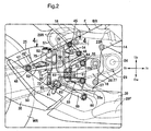
FIG. 2 is an enlarged view of a part indicated byarrow 2 ofFIG. 1 . -
FIG. 3 is a perspective view of a main part ofFIG. 2 . -
FIG. 4 is a cross-sectional view taken along line 4-4 ofFIG. 2 . -
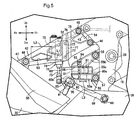
FIG. 5 is a side view corresponding to a part ofFIG. 2 , where a step movable-support member is moved to the forefront. -
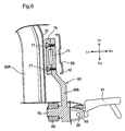
FIG. 6 is a cross-sectional view taken along line 6-6 ofFIG. 4 . - An embodiment of the present invention will be described with reference to the accompanying
FIGS. 1 to 6 . First, inFIG. 1 , a body frame F of a motorcycle includes: ahead pipe 13, which steerably supports afront fork 11 pivotally supporting a front wheel WF on its lower end part, and asteering handle 12 connected to thefront fork 11; paired right and leftmain frames 14 extending downward toward the rear from thehead pipe 13; paired right and left downframes 15 extending downward toward the rear from front parts of themain frames 14, at a steeper angle than the tilt angle of themain frames 14; paired right andleft pivot frames 16 extending downward, while being integrally connected to the rear ends of themain frames 14; paired right and left seat rails 17 having front end parts connected to longitudinal center parts of themain frames 14, and extending upward toward the rear; and paired right and leftauxiliary frames 18 having front end parts connected to rear end parts of themain frames 14 to extend upward toward the rear, and having rear end parts connected to longitudinal center parts of the seat rails 17. - An engine
main body 20 of an engine E exerting power for driving a rear wheel WR is mounted on the body frame F. In the embodiment, the enginemain body 20 configured as a V4 engine is supported to the body frame F while including: acrankcase 22, which rotatably supports acrankshaft 21 having a center axis parallel to rotation axes of the front wheel WF and rear wheel WR; and a front bank BF and rear bank BR, which are configured in a V shape opened upward and connected to a front upper part of thecrankcase 22. Each of the front bank BF and rear bank BR is configured of two cylinders. - A gearshift mechanism (not shown) is accommodated in the
crankcase 22, and anoutput shaft 24 of the gearshift mechanism protrudes to the side from a left side face of thecrankcase 22. Also, a front end part of aswing arm 25, which pivotally supports the rear wheel WR on a rear end part thereof, is swingably supported to thepivot frame 16 of the body frame F through aspindle 26. Rotary power from theoutput shaft 24 is transmitted to the rear wheel WR, through atransmission mechanism 28 including anendless drive chain 27. - Paired front
bank exhaust pipes 29F are connected to corresponding cylinders, on a front side wall of acylinder head 23F of the front bank BF, and paired rearbank exhaust pipes 29R are connected to corresponding cylinders, on a rear side wall of acylinder head 23R of the rear bank BR. The frontbank exhaust pipes 29F extend rearward while passing front to lower parts of thecrankcase 22, and the rearbank exhaust pipes 29R extend downward along upper to rear parts of thecrankcase 22, are arranged to turn to the lower side of thecrankcase 22, so that the frontbank exhaust pipes 29F and the rearbank exhaust pipes 29R are joined below a rear part of thecrankcase 22, and are connected to anexhaust muffler 30 arranged on the right side of the rear wheel WR. - An
intake system 31, which is connected to thecylinder heads fuel tank 32 supported by themain frames 14 is arranged behind theintake system 31 and above the enginemain body 20. Also, ariding seat 34, which is arranged in the rear obliquely upper direction of the engine E, is supported to the seat rails 17 of the body frame F. Thefuel tank 32 is formed such that its rear part extends toward a lower part of theriding seat 34. - A
front cowl 36 covers parts of thesteering handle 12 andhead pipe 13 from the front; paired right and leftfront side cowls 37 cover a front part of the engine E from both sides in the vehicle width direction; atop cowl 38 covers a top part of the engine E and a top part of thefuel tank 32, from above and both sides in the vehicle width direction; alower side cowl 39, which is continuous with thefront side cowls 37, covers a lower part of the engine E from both sides in the vehicle width direction; arear cowl 40, which is continuous with thetop cowl 38, covers a rear part of the body frame F; and thefront cowl 36, thefront side cowls 37, thetop cowl 38, thelower side cowl 39, and therear cowl 40 are supported to the body frame F. - Also referring to
FIGS. 2 to 4 , a bar-shapedmain step 41, on which the foot of a rider sitting on theriding seat 34 is placed, is supported to thepivot frame 16 of the body frame F, and theexhaust muffler 30 is supported by amuffler stay 42, which is attached to thepivot frame 16. - Moreover, paired
attachment portions pivot frame 16, in positions higher than themain step 41. Front end parts of the muffler stay 42 are attached to theattachment portions bolts attachment portions attachment portions plate 47, which is provided in an upper part of theexhaust muffler 30 close to the front end thereof, is fastened to a rear end part of the muffler stay 42, with abolt 48 and aweld nut 49 fixed to the attachedplate 47. Also, a front part of theexhaust muffler 30 is covered from above with a heat insulatingmuffler cover 50, and themuffler cover 50 is supported by theexhaust muffler 30. - The paired rear
bank exhaust pipes 29R are arranged on the inner side in the vehicle width direction of the muffler stay 42, in such a manner as to partially overlap with the muffler stay 42 in side view. A heat insulatingexhaust pipe cover 51, which covers the rearbank exhaust pipes 29R from the outer side in the vehicle width direction, is fixedly arranged on the inner side in the vehicle width direction of themuffler stay 42. - Also, the
muffler stay 42 is arranged on the inner side in the vehicle width direction of and above themain step 41, and tilts downward toward the rear. Hence, the muffler stay also functions as a heel guard for the rider placing his/her foot on themain step 41. Here, "function as a heel guard" means that the heel or ankle of the rider is brought into contact with the part, so that the rider can sandwich the vehicle with the legs to more easily fix his/her position. - Also referring to
FIG. 5 , amain step stay 55 arranged below themuffler stay 42, is fixed to thepivot frame 16 of the body frame F. Themain step stay 55 includes, as one body, a lowerattachment arm portion 55a extending in the longitudinal direction of the vehicle; an upperattachment arm portion 55b arranged above the lowerattachment arm portion 55a, and tilted upward toward the front such that a gap between itself and the lowerattachment arm portion 55a increases toward the vehicle front; and aconnection portion 55c connecting rear parts of the lowerattachment arm portion 55 and the upperattachment arm portion 55b, and forming aguide groove 56, which opens toward the outer side in the vehicle width direction and extends in the longitudinal direction of the vehicle, between the rear parts of the lowerattachment arm portion 55a and the upperattachment arm portion 55b. Front end parts of the lowerattachment arm portion 55a and the upperattachment arm portion 55b are attached to a lower part of thepivot frame 16, withbolts - Also, a step-
movable support member 60 arranged on the inner side in the vehicle width direction of themuffler stay 42 is supported to themain step stay 55, in such a manner as to be movable in the longitudinal direction within a limited range. The step movable-support member 60 is formed to include, as one body, aguide arm portion 60a extending in the longitudinal direction of the vehicle, and slidably fitted into thegroove 56 of themain step stay 55, and astep support portion 60b extending downward from a rear end part of theguide arm portion 60a. - Multiple (three in the embodiment)
insertion holes 61 are formed in theguide arm portion 60a of the step movable-support member 60, such that they are spaced apart in the longitudinal direction of the vehicle, and have axes extending along the vertical direction. Meanwhile, aninsertion hole 62 for inserting abolt 64, which is selectively inserted into one of themultiple insertion holes 61 in theguide arm portion 60a, is provided in the upperattachment arm portion 55b of themain step stay 55, and ascrew hole 63 for screwing in thebolt 64, which is inserted into theinsertion hole 62 and selectively inserted into one of themultiple insertion holes 61, is provided in the lowerattachment arm portion 55a of themain step stay 55. - Accordingly, the step-
movable support member 60 is supported to themain step stay 55, in such a manner as to be movable in the longitudinal direction by selecting one of themultiple insertion holes 61 in theguide arm portion 60a, and moving to a position corresponding to theinsertion hole 62 and thescrew hole 63. As clearly shown inFIG. 5 , a state, where thebolt 64 is inserted into the rearend insertion hole 61 of themultiple insertion holes 61 aligned in the longitudinal direction, is the movable end of the step movable-support member 60 toward the front, and as clearly shown inFIGS. 2 and3 , a state, where thebolt 64 is inserted into the frontend insertion hole 61 of themultiple insertion holes 61, is the movable end of the step movable-support member 60 toward the rear. - Also referring to
FIG. 6 ,foot positioning portions main step 41 to determine the position of the foot on themain step 41, are formed in themuffler stay 42, such that they open at least on the outer face of the muffler stay 42 in the vehicle width direction. - In the embodiment, the
foot positioning portion 52 is formed as a concave part opened on the outer face of the muffler stay 42 in the vehicle width direction. Thefoot positioning portion 53 is formed in the muffler stay 42 behind thefoot positioning portion 52, as a through hole having both ends opened on inner and outer faces of the muffler stay 42 in the vehicle width direction, to function also as a lightening hole for reducing weight. Themuffler stay 42 also has alightening hole 54, which is arranged in front of thefoot positioning portion 52, in such a manner as to sandwich thefoot positioning portion 52 between itself and thefoot positioning portion 53. - Moreover, a longitudinal length L1 of the
foot positioning portion 52 and a longitudinal length L2 of thefoot positioning portion 53 in themuffler stay 42, are set larger than a longitudinally movable distance L3 of the step movable-support member 60 mentioned above. - A
bracket 65 is provided integrally with a lower outer face of thestep support portion 60b of the step movable-support member 60, and themain step 41 is rotatably supported to thebracket 65 through asupport pin 66. - A
brake pedal 68 for putting a brake on the rear wheel WR is arranged in front of themain step 41. Thebrake pedal 68 is provided on a front end part of alever 69, which is rotatably supported by ashaft 70 integrally embedded in the inner face of a lower part of thestep support portion 60b. - Also, a master cylinder
unit attachment portion 71, which is integrally connected with the upper end of thestep support portion 60b and extends upward, is provided in a rear part of the step movable-support member 60. Amaster cylinder unit 72, which outputs hydraulic pressure of the brake according to a pushing operation of thebrake pedal 68, is supported to the master cylinderunit attachment portion 71. - The
master cylinder unit 72 is configured of amaster cylinder 74, which has apiston rod 73 connected to and working in response to the movement of a rear end part of thelever 69, and areservoir 75 provided integrally with themaster cylinder 74. Anattachment plate 76 connected integrally with themaster cylinder 74 is attached to the master cylinderunit attachment portion 71, with paired upper andlower bolts 77. - Moreover, the master cylinder
unit attachment portion 71 and themaster cylinder unit 72 are arranged on the inner side in the vehicle width direction of themuffler stay 42, and on the outer side in the vehicle width direction of the heat insulatingexhaust pipe cover 51, which covers the rearbank exhaust pipes 29R from the outer side in the vehicle width direction. Hence, the master cylinderunit attachment portion 71 and themaster cylinder unit 72, which move together with the step movable-support member 60, move in the longitudinal direction on the inner side in the vehicle width direction of themuffler stay 42. - A
brake hose 78, which introduces hydraulic pressure of the brake for putting a brake on the rear wheel WR, is connected to themaster cylinder 74 of themaster cylinder unit 72. As shown inFIG. 2 , thebrake hose 78 is arranged on the inner side in the vehicle width direction of themuffler stay 42, in such a manner as to partially overlap with themuffler stay 42 in side view. - Next, effects of the embodiment will be described. The muffler stay 42 supporting the
exhaust muffler 30 is attached to theattachment portions main step 41; and themuffler stay 42 extends downward toward the rear from theattachment portions main step 41. Hence, there is no need for an exclusive member for a heel guard, and the number of parts can be reduced. Also, the structure around themain step 41 can be downsized and simplified. - Moreover, by reducing the number of parts, the muffler stay 42 can be configured to not project outward needlessly in the vehicle width direction. Hence, the rider can mount and dismount the vehicle more easily.
- Also, the
foot positioning portions main step 41 to determine the position of the foot on themain step 41, are formed on the outer face of themuffler stay 42. Hence, thefoot positioning portions main step 41, and facilitate the rider's operation of the vehicle. - Also, the
main step stay 55 is fixed to the body frame F; the step movable-support member 60 arranged on the inner side in the vehicle width direction of themuffler stay 42 is supported to themain step stay 55, in such a manner as to be movable in the longitudinal direction within a limited range; and themain step 41 is provided in the step movable-support member 60. Hence, the position of themain step 41 can be adjusted according to the rider's build. Moreover, the longitudinal lengths L1, L2 of thefoot positioning portions support member 60. Hence, even when the position of themain step 41 is moved in the longitudinal direction, thefoot positioning portions main step 41, and facilitate the rider's operation of the vehicle. - Also, the
brake pedal 68 for putting a brake on the rear wheel WR is arranged in front of themain step 41; themaster cylinder unit 72, which outputs hydraulic pressure of the brake according to a pushing operation of thebrake pedal 68, is supported to the master cylinderunit attachment portion 71 provided in the rear part of the step movable-support member 60; and the master cylinderunit attachment portion 71 and themaster cylinder unit 72 are arranged in positions where they move in the longitudinal direction, on the inner side in the vehicle width direction of themuffler stay 42. Hence, space on the inner side in the vehicle width direction of the muffler stay 42 can be utilized effectively, and mass centralization and downsizing can be achieved. - Also, since the muffler stay 42 covers the
master cylinder unit 72 from the outer side in the vehicle width direction, themaster cylinder unit 72 can be arranged in a less recognizable position to improve appearance. - Furthermore, the
brake hose 78 connected to themaster cylinder unit 72 is arranged on the inner side in the vehicle width direction of themuffler stay 42, in such a manner as to partially overlap with themuffler stay 42 in side view. Hence, thebrake hose 78 can be made less recognizable to improve appearance of the motorcycle, and the structure around the muffler stay 42 can be downsized. - Although the embodiment of the present invention has been described, the invention is not limited to the above embodiment, and various design changes can be made without departing from the invention described in the scope of claims.
-
- 20 ...engine main body
- 30 ...exhaust muffler
- 41 ...main step
- 42 ...muffler stay
- 43, 44 ...attachment portion
- 52, 53 ...foot positioning portion
- 55 ...main step stay
- 60 ...step movable-support member
- 68 ...brake pedal
- 71 ...master cylinder unit attachment portion
- 72 ...master cylinder unit
- 78 ...brake hose
- E ...engine
- F ...body frame
- L1, L2 ...longitudinal length of foot positioning portion
- L3 ...longitudinally movable distance of step movable-support member
- WR ...rear wheel
Claims (5)
- A step structure of a motorcycle in which: an engine main body (20) of an engine (E), which exerts power for driving a rear wheel (WR), is mounted on a body frame (F); a main step (41) on which a rider's foot is placed is supported to said body frame (F); and an exhaust muffler (30), to which exhaust gas from said engine main body (20) is introduced, is supported by a muffler stay (42) attached to said body frame (F), wherein
said muffler stay (42), which is attached to an attachment portion (43, 44) provided in said body frame (F) above said main step (41), extends downward toward the rear from said attachment portion (43, 44), and functions as a heel guard for the rider placing his/her foot on said main step (41). - The step structure of a motorcycle according to claim 1, wherein
a foot positioning portion (52, 53) opened at least on an outer face of said muffler stay (42) in the vehicle width direction is formed in said muffler stay (42), in such a manner as to accommodate part of the rider's foot placed on said main step (41) to determine a position of said foot on said main step (41). - The step structure of a motorcycle according to claim 2, wherein:a main step stay (55) is fixed to said body frame (F) ;a step movable-support member (60) arranged on the inner side in the vehicle width direction of said muffler stay (42) is supported to said main step stay (55), in such a manner as to be movable in the longitudinal direction within a limited range;said main step (41) is provided in said step movable-support member (60); anda longitudinal length (L1, L2) of said foot positioning portion (52, 53) is set larger than a longitudinally movable distance (L3) of said step movable-support member (60).
- The step structure of a motorcycle according to claim 3, wherein:a brake pedal (68) for putting a brake on said rear wheel (WR) is arranged in front of said main step (41);a master cylinder unit (72), which outputs hydraulic pressure of a brake according to a pushing operation of said brake pedal (68), is supported to a master cylinder unit attachment portion (71) provided in a rear part of said step movable-support member (60); andsaid master cylinder unit attachment portion (71) and said master cylinder unit (72) are arranged in positions where they move in the longitudinal direction, on the inner side in the vehicle width direction of said muffler stay (42).
- The step structure of a motorcycle according to claim 4, wherein
a brake hose (78) connected to said master cylinder unit (72) is arranged on the inner side in the vehicle width direction of said muffler stay (42), in such a manner as to partially overlap with said muffler stay (42) in side view.
Applications Claiming Priority (1)
| Application Number | Priority Date | Filing Date | Title |
|---|---|---|---|
| JP2015157051A JP6141924B2 (en) | 2015-08-07 | 2015-08-07 | Step structure in motorcycles |
Publications (2)
| Publication Number | Publication Date |
|---|---|
| EP3127797A1 true EP3127797A1 (en) | 2017-02-08 |
| EP3127797B1 EP3127797B1 (en) | 2018-01-24 |
Family
ID=56550027
Family Applications (1)
| Application Number | Title | Priority Date | Filing Date |
|---|---|---|---|
| EP16178944.1A Active EP3127797B1 (en) | 2015-08-07 | 2016-07-12 | Step structure of motorcycle |
Country Status (3)
| Country | Link |
|---|---|
| US (1) | US9809268B2 (en) |
| EP (1) | EP3127797B1 (en) |
| JP (1) | JP6141924B2 (en) |
Cited By (2)
| Publication number | Priority date | Publication date | Assignee | Title |
|---|---|---|---|---|
| US11377081B2 (en) * | 2019-03-18 | 2022-07-05 | Honda Motor Co., Ltd. | Brake pedal structure for saddled vehicle |
| DE102021128675A1 (en) | 2021-11-04 | 2023-05-04 | Bayerische Motoren Werke Aktiengesellschaft | Footrest for a motorcycle and motorcycle with such a footrest |
Families Citing this family (6)
| Publication number | Priority date | Publication date | Assignee | Title |
|---|---|---|---|---|
| EP3412554B1 (en) * | 2016-02-05 | 2020-04-15 | Honda Motor Co., Ltd. | Saddle-type vehicle |
| JP6902887B2 (en) * | 2017-03-23 | 2021-07-14 | 川崎重工業株式会社 | Manufacturing method of saddle type vehicle, step mounting member, and step mounting member |
| US20190092415A1 (en) * | 2017-09-27 | 2019-03-28 | Zane Campbell | Motorcycle frame support bracket |
| US10953945B2 (en) * | 2018-10-29 | 2021-03-23 | Kuryakyn Holdings, LLC | Mounting assembly for a motorcycle peg |
| JP6813604B2 (en) * | 2019-01-11 | 2021-01-13 | フタバ産業株式会社 | Exhaust parts equipment |
| CN117916145A (en) * | 2021-09-13 | 2024-04-19 | 印度摩托车国际有限公司 | Vehicle with a vehicle body having a vehicle body support |
Citations (3)
| Publication number | Priority date | Publication date | Assignee | Title |
|---|---|---|---|---|
| JP2002264868A (en) * | 2001-03-06 | 2002-09-18 | Honda Motor Co Ltd | Step holder device for motorcycle |
| JP2011088522A (en) * | 2009-10-21 | 2011-05-06 | Honda Motor Co Ltd | Step peripheral structure of saddle riding type vehicle |
| JP2013226977A (en) | 2012-04-26 | 2013-11-07 | Honda Motor Co Ltd | Step structure of saddle type vehicle |
Family Cites Families (17)
| Publication number | Priority date | Publication date | Assignee | Title |
|---|---|---|---|---|
| US4023821A (en) * | 1976-04-05 | 1977-05-17 | Eiland John H | Heat shielding foot rest for attachment to a motorcycle exhaust system |
| JP2905466B2 (en) * | 1997-09-22 | 1999-06-14 | ヤマハ発動機株式会社 | Exhaust pipe support for motorcycles |
| JP4298835B2 (en) * | 1999-01-22 | 2009-07-22 | 本田技研工業株式会社 | Motorcycle exhaust system |
| JP2006315657A (en) * | 2005-07-05 | 2006-11-24 | Honda Motor Co Ltd | Arrangement structure of motorcycle muffler and brake pedal |
| JP4855201B2 (en) * | 2006-10-06 | 2012-01-18 | ヤマハ発動機株式会社 | Motorcycle |
| JP2009108824A (en) * | 2007-10-31 | 2009-05-21 | Yamaha Motor Co Ltd | Motorcycle |
| JP2009234531A (en) * | 2008-03-28 | 2009-10-15 | Yamaha Motor Co Ltd | Bracket for fixing muffler and straddle type vehicle therewith |
| JP5025582B2 (en) * | 2008-07-07 | 2012-09-12 | 本田技研工業株式会社 | Motorcycle |
| JP5400723B2 (en) * | 2010-07-16 | 2014-01-29 | 本田技研工業株式会社 | Saddle riding |
| JP5867852B2 (en) * | 2011-09-21 | 2016-02-24 | 本田技研工業株式会社 | Muffler device with protector for small vehicles |
| JP6058957B2 (en) * | 2012-09-21 | 2017-01-11 | 本田技研工業株式会社 | Side cover structure for saddle-ride type vehicles |
| JP5773975B2 (en) * | 2012-12-26 | 2015-09-02 | 本田技研工業株式会社 | Exhaust pipe cover structure for saddle-ride type vehicles |
| WO2014181651A1 (en) * | 2013-05-10 | 2014-11-13 | 川崎重工業株式会社 | Motorcycle |
| EP2995539B1 (en) * | 2013-05-10 | 2019-06-12 | Kawasaki Jukogyo Kabushiki Kaisha | Supporting structure for rear parts of a motorcycle |
| JP2016032949A (en) * | 2014-07-30 | 2016-03-10 | 本田技研工業株式会社 | Step structure in saddle-ride type vehicle |
| JP6086889B2 (en) * | 2014-09-30 | 2017-03-01 | 本田技研工業株式会社 | Rear fuel tank |
| JP5997307B2 (en) * | 2015-02-25 | 2016-09-28 | 本田技研工業株式会社 | Exhaust structure of saddle-ride type vehicle |
-
2015
- 2015-08-07 JP JP2015157051A patent/JP6141924B2/en active Active
-
2016
- 2016-07-12 EP EP16178944.1A patent/EP3127797B1/en active Active
- 2016-07-28 US US15/222,055 patent/US9809268B2/en not_active Expired - Fee Related
Patent Citations (3)
| Publication number | Priority date | Publication date | Assignee | Title |
|---|---|---|---|---|
| JP2002264868A (en) * | 2001-03-06 | 2002-09-18 | Honda Motor Co Ltd | Step holder device for motorcycle |
| JP2011088522A (en) * | 2009-10-21 | 2011-05-06 | Honda Motor Co Ltd | Step peripheral structure of saddle riding type vehicle |
| JP2013226977A (en) | 2012-04-26 | 2013-11-07 | Honda Motor Co Ltd | Step structure of saddle type vehicle |
Cited By (3)
| Publication number | Priority date | Publication date | Assignee | Title |
|---|---|---|---|---|
| US11377081B2 (en) * | 2019-03-18 | 2022-07-05 | Honda Motor Co., Ltd. | Brake pedal structure for saddled vehicle |
| DE102021128675A1 (en) | 2021-11-04 | 2023-05-04 | Bayerische Motoren Werke Aktiengesellschaft | Footrest for a motorcycle and motorcycle with such a footrest |
| DE102021128675B4 (en) | 2021-11-04 | 2024-03-07 | Bayerische Motoren Werke Aktiengesellschaft | Footrest for a motorcycle and motorcycle with such a footrest |
Also Published As
| Publication number | Publication date |
|---|---|
| JP6141924B2 (en) | 2017-06-07 |
| US20170036727A1 (en) | 2017-02-09 |
| US9809268B2 (en) | 2017-11-07 |
| EP3127797B1 (en) | 2018-01-24 |
| JP2017035931A (en) | 2017-02-16 |
Similar Documents
| Publication | Publication Date | Title |
|---|---|---|
| EP3127797B1 (en) | Step structure of motorcycle | |
| JP5129672B2 (en) | Body cover structure for motorcycles | |
| JP5025582B2 (en) | Motorcycle | |
| US7870924B2 (en) | Arrangement structure of a rear master cylinder and a hydraulic fluid reservoir tank in a saddle-riding type vehicle, and motorcycle incorporating same | |
| JP5129673B2 (en) | Motorcycle | |
| EP3109147B1 (en) | Straddle type vehicle | |
| EP3127796B1 (en) | Rear structure of motorcycle | |
| EP1826086A1 (en) | Brake support structure | |
| JP5760513B2 (en) | Saddle riding vehicle | |
| JP2012245794A (en) | Two-wheeled motor vehicle | |
| US20030230445A1 (en) | Electrical bicycle with steering control by biasing the body | |
| EP1772359B1 (en) | Motorcycle | |
| EP2783968A1 (en) | Motorcycle | |
| JP2001114169A (en) | Scooter type vehicle | |
| WO2015141749A1 (en) | Straddled vehicle | |
| WO2015029520A1 (en) | Automatic two-wheeled vehicle | |
| JP2010228737A (en) | Motorcycle | |
| JP6851413B2 (en) | Saddle-type vehicle | |
| EP1762479B1 (en) | Two-wheeled motor vehicle | |
| EP1772366B1 (en) | Motorcycle | |
| CN100532188C (en) | Support structure of power unit of two-wheeled motorcycle | |
| JP4458991B2 (en) | Scooter type motorcycle | |
| CN106029488B (en) | The arragement construction of braking force transmission member on automatic two-wheeled cycle | |
| JP2012091662A (en) | Saddle-riding type vehicle | |
| JP4530787B2 (en) | Motorcycle |
Legal Events
| Date | Code | Title | Description |
|---|---|---|---|
| PUAI | Public reference made under article 153(3) epc to a published international application that has entered the european phase |
Free format text: ORIGINAL CODE: 0009012 |
|
| STAA | Information on the status of an ep patent application or granted ep patent |
Free format text: STATUS: REQUEST FOR EXAMINATION WAS MADE |
|
| 17P | Request for examination filed |
Effective date: 20160712 |
|
| AK | Designated contracting states |
Kind code of ref document: A1 Designated state(s): AL AT BE BG CH CY CZ DE DK EE ES FI FR GB GR HR HU IE IS IT LI LT LU LV MC MK MT NL NO PL PT RO RS SE SI SK SM TR |
|
| AX | Request for extension of the european patent |
Extension state: BA ME |
|
| GRAP | Despatch of communication of intention to grant a patent |
Free format text: ORIGINAL CODE: EPIDOSNIGR1 |
|
| STAA | Information on the status of an ep patent application or granted ep patent |
Free format text: STATUS: GRANT OF PATENT IS INTENDED |
|
| RIC1 | Information provided on ipc code assigned before grant |
Ipc: B62L 3/04 20060101ALI20170814BHEP Ipc: B62K 11/04 20060101ALI20170814BHEP Ipc: B62M 7/02 20060101ALI20170814BHEP Ipc: B62J 25/00 20060101AFI20170814BHEP Ipc: B62J 23/00 20060101ALI20170814BHEP |
|
| INTG | Intention to grant announced |
Effective date: 20170831 |
|
| GRAS | Grant fee paid |
Free format text: ORIGINAL CODE: EPIDOSNIGR3 |
|
| GRAA | (expected) grant |
Free format text: ORIGINAL CODE: 0009210 |
|
| STAA | Information on the status of an ep patent application or granted ep patent |
Free format text: STATUS: THE PATENT HAS BEEN GRANTED |
|
| AK | Designated contracting states |
Kind code of ref document: B1 Designated state(s): AL AT BE BG CH CY CZ DE DK EE ES FI FR GB GR HR HU IE IS IT LI LT LU LV MC MK MT NL NO PL PT RO RS SE SI SK SM TR |
|
| REG | Reference to a national code |
Ref country code: GB Ref legal event code: FG4D |
|
| REG | Reference to a national code |
Ref country code: CH Ref legal event code: EP |
|
| REG | Reference to a national code |
Ref country code: AT Ref legal event code: REF Ref document number: 965610 Country of ref document: AT Kind code of ref document: T Effective date: 20180215 |
|
| REG | Reference to a national code |
Ref country code: IE Ref legal event code: FG4D |
|
| REG | Reference to a national code |
Ref country code: DE Ref legal event code: R096 Ref document number: 602016001446 Country of ref document: DE |
|
| REG | Reference to a national code |
Ref country code: NL Ref legal event code: MP Effective date: 20180124 |
|
| REG | Reference to a national code |
Ref country code: LT Ref legal event code: MG4D |
|
| REG | Reference to a national code |
Ref country code: AT Ref legal event code: MK05 Ref document number: 965610 Country of ref document: AT Kind code of ref document: T Effective date: 20180124 |
|
| PG25 | Lapsed in a contracting state [announced via postgrant information from national office to epo] |
Ref country code: NL Free format text: LAPSE BECAUSE OF FAILURE TO SUBMIT A TRANSLATION OF THE DESCRIPTION OR TO PAY THE FEE WITHIN THE PRESCRIBED TIME-LIMIT Effective date: 20180124 |
|
| PG25 | Lapsed in a contracting state [announced via postgrant information from national office to epo] |
Ref country code: LT Free format text: LAPSE BECAUSE OF FAILURE TO SUBMIT A TRANSLATION OF THE DESCRIPTION OR TO PAY THE FEE WITHIN THE PRESCRIBED TIME-LIMIT Effective date: 20180124 Ref country code: CY Free format text: LAPSE BECAUSE OF FAILURE TO SUBMIT A TRANSLATION OF THE DESCRIPTION OR TO PAY THE FEE WITHIN THE PRESCRIBED TIME-LIMIT Effective date: 20180124 Ref country code: HR Free format text: LAPSE BECAUSE OF FAILURE TO SUBMIT A TRANSLATION OF THE DESCRIPTION OR TO PAY THE FEE WITHIN THE PRESCRIBED TIME-LIMIT Effective date: 20180124 Ref country code: ES Free format text: LAPSE BECAUSE OF FAILURE TO SUBMIT A TRANSLATION OF THE DESCRIPTION OR TO PAY THE FEE WITHIN THE PRESCRIBED TIME-LIMIT Effective date: 20180124 Ref country code: FI Free format text: LAPSE BECAUSE OF FAILURE TO SUBMIT A TRANSLATION OF THE DESCRIPTION OR TO PAY THE FEE WITHIN THE PRESCRIBED TIME-LIMIT Effective date: 20180124 Ref country code: NO Free format text: LAPSE BECAUSE OF FAILURE TO SUBMIT A TRANSLATION OF THE DESCRIPTION OR TO PAY THE FEE WITHIN THE PRESCRIBED TIME-LIMIT Effective date: 20180424 |
|
| PG25 | Lapsed in a contracting state [announced via postgrant information from national office to epo] |
Ref country code: AT Free format text: LAPSE BECAUSE OF FAILURE TO SUBMIT A TRANSLATION OF THE DESCRIPTION OR TO PAY THE FEE WITHIN THE PRESCRIBED TIME-LIMIT Effective date: 20180124 Ref country code: RS Free format text: LAPSE BECAUSE OF FAILURE TO SUBMIT A TRANSLATION OF THE DESCRIPTION OR TO PAY THE FEE WITHIN THE PRESCRIBED TIME-LIMIT Effective date: 20180124 Ref country code: PL Free format text: LAPSE BECAUSE OF FAILURE TO SUBMIT A TRANSLATION OF THE DESCRIPTION OR TO PAY THE FEE WITHIN THE PRESCRIBED TIME-LIMIT Effective date: 20180124 Ref country code: BG Free format text: LAPSE BECAUSE OF FAILURE TO SUBMIT A TRANSLATION OF THE DESCRIPTION OR TO PAY THE FEE WITHIN THE PRESCRIBED TIME-LIMIT Effective date: 20180424 Ref country code: GR Free format text: LAPSE BECAUSE OF FAILURE TO SUBMIT A TRANSLATION OF THE DESCRIPTION OR TO PAY THE FEE WITHIN THE PRESCRIBED TIME-LIMIT Effective date: 20180425 Ref country code: LV Free format text: LAPSE BECAUSE OF FAILURE TO SUBMIT A TRANSLATION OF THE DESCRIPTION OR TO PAY THE FEE WITHIN THE PRESCRIBED TIME-LIMIT Effective date: 20180124 Ref country code: SE Free format text: LAPSE BECAUSE OF FAILURE TO SUBMIT A TRANSLATION OF THE DESCRIPTION OR TO PAY THE FEE WITHIN THE PRESCRIBED TIME-LIMIT Effective date: 20180124 Ref country code: IS Free format text: LAPSE BECAUSE OF FAILURE TO SUBMIT A TRANSLATION OF THE DESCRIPTION OR TO PAY THE FEE WITHIN THE PRESCRIBED TIME-LIMIT Effective date: 20180524 |
|
| REG | Reference to a national code |
Ref country code: DE Ref legal event code: R097 Ref document number: 602016001446 Country of ref document: DE |
|
| PG25 | Lapsed in a contracting state [announced via postgrant information from national office to epo] |
Ref country code: AL Free format text: LAPSE BECAUSE OF FAILURE TO SUBMIT A TRANSLATION OF THE DESCRIPTION OR TO PAY THE FEE WITHIN THE PRESCRIBED TIME-LIMIT Effective date: 20180124 Ref country code: RO Free format text: LAPSE BECAUSE OF FAILURE TO SUBMIT A TRANSLATION OF THE DESCRIPTION OR TO PAY THE FEE WITHIN THE PRESCRIBED TIME-LIMIT Effective date: 20180124 Ref country code: EE Free format text: LAPSE BECAUSE OF FAILURE TO SUBMIT A TRANSLATION OF THE DESCRIPTION OR TO PAY THE FEE WITHIN THE PRESCRIBED TIME-LIMIT Effective date: 20180124 |
|
| PG25 | Lapsed in a contracting state [announced via postgrant information from national office to epo] |
Ref country code: SK Free format text: LAPSE BECAUSE OF FAILURE TO SUBMIT A TRANSLATION OF THE DESCRIPTION OR TO PAY THE FEE WITHIN THE PRESCRIBED TIME-LIMIT Effective date: 20180124 Ref country code: CZ Free format text: LAPSE BECAUSE OF FAILURE TO SUBMIT A TRANSLATION OF THE DESCRIPTION OR TO PAY THE FEE WITHIN THE PRESCRIBED TIME-LIMIT Effective date: 20180124 Ref country code: DK Free format text: LAPSE BECAUSE OF FAILURE TO SUBMIT A TRANSLATION OF THE DESCRIPTION OR TO PAY THE FEE WITHIN THE PRESCRIBED TIME-LIMIT Effective date: 20180124 Ref country code: SM Free format text: LAPSE BECAUSE OF FAILURE TO SUBMIT A TRANSLATION OF THE DESCRIPTION OR TO PAY THE FEE WITHIN THE PRESCRIBED TIME-LIMIT Effective date: 20180124 |
|
| PLBE | No opposition filed within time limit |
Free format text: ORIGINAL CODE: 0009261 |
|
| STAA | Information on the status of an ep patent application or granted ep patent |
Free format text: STATUS: NO OPPOSITION FILED WITHIN TIME LIMIT |
|
| 26N | No opposition filed |
Effective date: 20181025 |
|
| PG25 | Lapsed in a contracting state [announced via postgrant information from national office to epo] |
Ref country code: SI Free format text: LAPSE BECAUSE OF FAILURE TO SUBMIT A TRANSLATION OF THE DESCRIPTION OR TO PAY THE FEE WITHIN THE PRESCRIBED TIME-LIMIT Effective date: 20180124 |
|
| PG25 | Lapsed in a contracting state [announced via postgrant information from national office to epo] |
Ref country code: LU Free format text: LAPSE BECAUSE OF NON-PAYMENT OF DUE FEES Effective date: 20180712 Ref country code: MC Free format text: LAPSE BECAUSE OF FAILURE TO SUBMIT A TRANSLATION OF THE DESCRIPTION OR TO PAY THE FEE WITHIN THE PRESCRIBED TIME-LIMIT Effective date: 20180124 |
|
| REG | Reference to a national code |
Ref country code: BE Ref legal event code: MM Effective date: 20180731 |
|
| REG | Reference to a national code |
Ref country code: IE Ref legal event code: MM4A |
|
| PG25 | Lapsed in a contracting state [announced via postgrant information from national office to epo] |
Ref country code: FR Free format text: LAPSE BECAUSE OF NON-PAYMENT OF DUE FEES Effective date: 20180731 Ref country code: IE Free format text: LAPSE BECAUSE OF NON-PAYMENT OF DUE FEES Effective date: 20180712 |
|
| PG25 | Lapsed in a contracting state [announced via postgrant information from national office to epo] |
Ref country code: BE Free format text: LAPSE BECAUSE OF NON-PAYMENT OF DUE FEES Effective date: 20180731 |
|
| PGFP | Annual fee paid to national office [announced via postgrant information from national office to epo] |
Ref country code: IT Payment date: 20190731 Year of fee payment: 4 |
|
| REG | Reference to a national code |
Ref country code: DE Ref legal event code: R084 Ref document number: 602016001446 Country of ref document: DE |
|
| PG25 | Lapsed in a contracting state [announced via postgrant information from national office to epo] |
Ref country code: MT Free format text: LAPSE BECAUSE OF NON-PAYMENT OF DUE FEES Effective date: 20180712 |
|
| REG | Reference to a national code |
Ref country code: CH Ref legal event code: PL |
|
| PG25 | Lapsed in a contracting state [announced via postgrant information from national office to epo] |
Ref country code: TR Free format text: LAPSE BECAUSE OF FAILURE TO SUBMIT A TRANSLATION OF THE DESCRIPTION OR TO PAY THE FEE WITHIN THE PRESCRIBED TIME-LIMIT Effective date: 20180124 |
|
| PG25 | Lapsed in a contracting state [announced via postgrant information from national office to epo] |
Ref country code: LI Free format text: LAPSE BECAUSE OF NON-PAYMENT OF DUE FEES Effective date: 20190731 Ref country code: CH Free format text: LAPSE BECAUSE OF NON-PAYMENT OF DUE FEES Effective date: 20190731 Ref country code: PT Free format text: LAPSE BECAUSE OF FAILURE TO SUBMIT A TRANSLATION OF THE DESCRIPTION OR TO PAY THE FEE WITHIN THE PRESCRIBED TIME-LIMIT Effective date: 20180124 |
|
| PG25 | Lapsed in a contracting state [announced via postgrant information from national office to epo] |
Ref country code: MK Free format text: LAPSE BECAUSE OF NON-PAYMENT OF DUE FEES Effective date: 20180124 Ref country code: HU Free format text: LAPSE BECAUSE OF FAILURE TO SUBMIT A TRANSLATION OF THE DESCRIPTION OR TO PAY THE FEE WITHIN THE PRESCRIBED TIME-LIMIT; INVALID AB INITIO Effective date: 20160712 |
|
| GBPC | Gb: european patent ceased through non-payment of renewal fee |
Effective date: 20200712 |
|
| PG25 | Lapsed in a contracting state [announced via postgrant information from national office to epo] |
Ref country code: GB Free format text: LAPSE BECAUSE OF NON-PAYMENT OF DUE FEES Effective date: 20200712 |
|
| PG25 | Lapsed in a contracting state [announced via postgrant information from national office to epo] |
Ref country code: IT Free format text: LAPSE BECAUSE OF NON-PAYMENT OF DUE FEES Effective date: 20200712 |
|
| PGFP | Annual fee paid to national office [announced via postgrant information from national office to epo] |
Ref country code: DE Payment date: 20250620 Year of fee payment: 10 |