EP3127424B1 - A drip irrigation hose with strip - Google Patents
A drip irrigation hose with strip Download PDFInfo
- Publication number
- EP3127424B1 EP3127424B1 EP15180002.6A EP15180002A EP3127424B1 EP 3127424 B1 EP3127424 B1 EP 3127424B1 EP 15180002 A EP15180002 A EP 15180002A EP 3127424 B1 EP3127424 B1 EP 3127424B1
- Authority
- EP
- European Patent Office
- Prior art keywords
- strip
- profiles
- water
- section
- hose
- Prior art date
- Legal status (The legal status is an assumption and is not a legal conclusion. Google has not performed a legal analysis and makes no representation as to the accuracy of the status listed.)
- Active
Links
Images


Classifications
-
- A—HUMAN NECESSITIES
- A01—AGRICULTURE; FORESTRY; ANIMAL HUSBANDRY; HUNTING; TRAPPING; FISHING
- A01G—HORTICULTURE; CULTIVATION OF VEGETABLES, FLOWERS, RICE, FRUIT, VINES, HOPS OR SEAWEED; FORESTRY; WATERING
- A01G25/00—Watering gardens, fields, sports grounds or the like
- A01G25/02—Watering arrangements located above the soil which make use of perforated pipe-lines or pipe-lines with dispensing fittings, e.g. for drip irrigation
- A01G25/023—Dispensing fittings for drip irrigation, e.g. drippers
-
- A—HUMAN NECESSITIES
- A01—AGRICULTURE; FORESTRY; ANIMAL HUSBANDRY; HUNTING; TRAPPING; FISHING
- A01G—HORTICULTURE; CULTIVATION OF VEGETABLES, FLOWERS, RICE, FRUIT, VINES, HOPS OR SEAWEED; FORESTRY; WATERING
- A01G25/00—Watering gardens, fields, sports grounds or the like
- A01G25/02—Watering arrangements located above the soil which make use of perforated pipe-lines or pipe-lines with dispensing fittings, e.g. for drip irrigation
-
- B—PERFORMING OPERATIONS; TRANSPORTING
- B05—SPRAYING OR ATOMISING IN GENERAL; APPLYING FLUENT MATERIALS TO SURFACES, IN GENERAL
- B05B—SPRAYING APPARATUS; ATOMISING APPARATUS; NOZZLES
- B05B1/00—Nozzles, spray heads or other outlets, with or without auxiliary devices such as valves, heating means
- B05B1/30—Nozzles, spray heads or other outlets, with or without auxiliary devices such as valves, heating means designed to control volume of flow, e.g. with adjustable passages
- B05B1/3006—Nozzles, spray heads or other outlets, with or without auxiliary devices such as valves, heating means designed to control volume of flow, e.g. with adjustable passages the controlling element being actuated by the pressure of the fluid to be sprayed
-
- B—PERFORMING OPERATIONS; TRANSPORTING
- B05—SPRAYING OR ATOMISING IN GENERAL; APPLYING FLUENT MATERIALS TO SURFACES, IN GENERAL
- B05B—SPRAYING APPARATUS; ATOMISING APPARATUS; NOZZLES
- B05B1/00—Nozzles, spray heads or other outlets, with or without auxiliary devices such as valves, heating means
- B05B1/30—Nozzles, spray heads or other outlets, with or without auxiliary devices such as valves, heating means designed to control volume of flow, e.g. with adjustable passages
- B05B1/3013—Lift valves
-
- Y—GENERAL TAGGING OF NEW TECHNOLOGICAL DEVELOPMENTS; GENERAL TAGGING OF CROSS-SECTIONAL TECHNOLOGIES SPANNING OVER SEVERAL SECTIONS OF THE IPC; TECHNICAL SUBJECTS COVERED BY FORMER USPC CROSS-REFERENCE ART COLLECTIONS [XRACs] AND DIGESTS
- Y02—TECHNOLOGIES OR APPLICATIONS FOR MITIGATION OR ADAPTATION AGAINST CLIMATE CHANGE
- Y02A—TECHNOLOGIES FOR ADAPTATION TO CLIMATE CHANGE
- Y02A40/00—Adaptation technologies in agriculture, forestry, livestock or agroalimentary production
- Y02A40/10—Adaptation technologies in agriculture, forestry, livestock or agroalimentary production in agriculture
- Y02A40/22—Improving land use; Improving water use or availability; Controlling erosion
Definitions
- the present invention relates to a continuous-type emitter for distributing water in a constant flow rate.
- the present invention provides means for water distribution by using a pressure compensating strip such as a continuouos emitter having a first profiles and a second profiles in a regulating section, thus allows for excellent fine-tuning of water flow rate and water pressure regulation.
- irrigation systems There are several types of irrigation systems widely used nowadays, depending on how the water is distributed throughout the field. Some common types of irrigation systems include, for example, surface irrigation, sprinkler irrigation and localized irrigation. In surface irrigation, water is distributed over and across land by gravity, and no mechanical pump involved. In sprinkler irrigation, water is distributed by overhead high-pressure sprinklers or guns from a central location in the field or from sprinklers on moving platforms.
- Drip irrigation is a type of localized irrigation in which drops of water are delivered at or near the root of plants. In this type of irrigation, evaporation and runoff are minimized.
- a type of discrete emitter has been widely used in the drip irrigation system. However, such discrete emitter often consists of multiple parts, thus entails higher production cost, and therefore is less favorable in some instances due to economical reasons.
- Discrete emitters are commonly being used when a larger distance of water outlets are required, for instance a water outlet in about every 20cm or more for each segment water outlet. In this case, discrete emitters are more economically to be used compared to a continuous emitter. When water outlets are needed to be repeated in a shorter distance, for example less than every 20 cm, an elongated emitter is advantageuously a more favorable option.
- some types of continuous emitter may consist of flexible tunnel-like emitter. Said tunnel-like emitter reduces water pressure (and hence water outflow rate) when water pressure of the hose is high.
- Said type of flexible emitters face problems of higher fluctuation of water outflow, as water could bypass the tunnel-like emitter. Fine-tuning of the water outflow and/or water pressure thus fails to be realised in such kind of continuous emitter.
- the inventors of the present invention have surprisingly found out that the above-formulated need can be met by creating a specially-designed strip that is pressure-compensated, elastic, able to fine-tune water flow rate and regulate water pressure as defined in claim 1.
- the strip is provided to be able to simultaneously response, regulate and reduce water flow rate and/or water pressure thanks to an array of specially designed profiles in a regulating section of the strip as claimed. This advantageously allows for a lower cost of production, shorter labyrinth segment, hence allowing for more repetitive labyrinth segments and more water outlets within a shorter distance.
- water is able to be distributed through outlets on the drip irrigation hose in a shorter distance, for example, less than about 10 cm, or even less than 5 cm without affecting the water flow rate of the pressure compensating strip.
- water pressure and water outflow can be better fine-tuned thanks to the different profiles provided in the regulating section of the strip, as water flows through the entire length of labyrinth segment of the strip. Under higher water pressure condition, certain profiles are pushed towards the hose, thereby creating additional barrier within the labyrinth. This enables water pressure to be regulated in an optimal condtion, allowing fine-tuning of water outflow condition and water pressure in the strip.
- the present invention therefore relates to a strip for distributing water, said strip has a repetitive labyrinth segment, wherein a plurality of profiles are provided to the base of the strip, said labyrinth segment comprises: a water input section; a regulating section arranged downstream from the water input section, wherein said regulating section is provided to regulate water flow rate of the strip in response to water pressure of a hose; a discharge section arranged downstream from the regulating section, wherein said discharge section is provided with deflection-resistant reinforcement means.
- the discharge section of the strip according to the present invention allows water to be evenly distributed in a controllable manner, as reinforcement means is provided to reduce frequency of deflection caused by water pressures which exits from the outlets.
- the present invention relates to a pressure compensating drip irrigation hose comprising the aforementioned strip as described herein.
- said strip is made of at least one elastomeric material. This advantageously allows for not only a lower cost of production and easier production, it allows for the drip irrigation hose to be arranged in all possible positions without hindering the flexibility of the hose.
- the water input section is provided with a filter means. This advantageously allows for water to be filtered before entering into the regulating section.
- the distance between the profiles in the input section are less than the distance between the profiles in the regulating section. This advantageously prevents particles larger than the gap between profiles in the water input section to be entered into the regulating section of the strip.
- the strip has two rails, forming side walls of the strip.
- the rails could exist in both the regulating section and the discharge section. This allows water to enter into the strip only through the water input section which has a filter means to filter out certain particles having diameter larger than the gap between profiles of water input section. The filtered water then flows along the labyrinth segment.
- said profiles in the regulating section comprises a first profile, and a second profile, wherein the first profiles are a rectangular-shaped block whereas the second profiles have a wedge shape.
- the first profiles, and the second profile in the regulating section have a barrier-like partition structure extended from the rails of the strip.
- the first profiles are advantageusly designed to set a limitation of a fixed volume of water flowing in the strip. This allows for a certain predetermined water flow rate and/or water pressure flowing in the strip. This prevents voids of the strip to collapse under situation where water pressure is extremely high in the hose.
- the second profiles of the regulating section are advantageously designed to be able to response, regulate and reduce water pressure and/or water flow rate of the strip according to water pressure within the drip irrigation hose.
- water flows along the entire labyrinth segment of the strip.
- the first profiles allow for a maximum volume of water flowing in the strip;
- the second profiles fine-tune water pressure and/or water flow rate of the strip depending on the water pressure of the hose.
- the entire top surface of the first profiles opposite to the base of the strip are connected to an inner part of a hose. This allows said type of first profiles to be fixed permanently between the strip and the hose, thus allowing a fixed volume of water flowing within the strip.
- the profiles in the regulating section are provided in an alternative and regular or irregular fashion throughout the repeated labyrinth segment.
- higher number of the second profiles having a wedge shape than the first profiles could be arranged in the regulating section of the strip.
- less number of the second profiles than the first profiles can be used to achieve the aforementioned goal.
- the discharge section is provided with interconnected reinforcements to increase the resistance of deflection.
- the interconnected reinforcements are provided at the base of the strip. This fortifies said section, allowing for a stronger structure.
- the interconnected reinforcements have height less than the top surface of the rails of the strip so that their influence on disturbing water flow rate is minimised.
- the strip is provided at an inner surface of the drip irrigation hose.
- the strip is made up of material less stiff than the drip irrigation hose so that the flexibility of the hose is not affected by the strip operatively connected within.
- At least one outlet of the hose is provided at the discharge section of the strip. This allows for instaneously water outflow.
- the outlet is an open-end outlet or a slit. Both open end outlet and slit outlet allow water to be emitted easily Furthermore, slit outlets further prevent the roots of the plants from growing into the drip irrigation hose.
- the labyrinth segment of the strip according to the present invention is able to be designed in various length, for instance less than 10cm. It is possible to be less than 8 cm. It is also designed for less than 5 cm without affecting the functionality of the pressure compesating strip and its water flow rate as well as fine-tuning its response to water pressure of the hose.
- a new strip (1) connected to a drip irrigation hose (9) for distributing water is espoused.
- Said strip (1) comprised of a repetitive labyrinth segment (2, 2'), the labyrinth segment has a water input section (3, 3'), followed by a regulating section (4, 4') and subsequently a discharge section (5, 5'), wherein a plurality of profiles (21, 24, 25, 26) are provided to the base (15) of the strip (1), wherein said regulating section (4, 4') is provided to regulate water flow rate of the strip (1) in response of water pressure of a hose. It also simultaneously regulates and responses to water pressure within a certain predetermined water pressure level; a discharge section (5, 5') arranged downstream from the regulating section (4, 4'), wherein said discharge section is provided with deflection-resistant reinforcement means.
- FIG. 1 shows a schematic representation of an exemplary embodiment of the strip not according to the present invention.
- the strip 1 has a repetitive labyrinth segment 2, 2', 2". In each segment of the labyrinth, it is comprised of a water input section 3, 3'; a regulating section 4, 4'; and a discharge section 5, 5'.
- the strip 1 can be made up of any elastomeric materials such as thermoplastic elastomeric synthetic polymer or natural rubber including commonly used polymers such as Polybutadiene, EVA and etc.
- FIG. 2A-C show enlarged top plan of a water input section ( Fig. 2A ), a regulating section ( Fig. 2B ) and a discharge section ( Fig. 2C ).
- a plurality of profiles 21 are provided at the base (15) of the strip 1.
- two rows of closely-aligned profiles 21 are arranged at the water input section 3, 3'.
- a gap GPI exists between each profiles 21 of the water input section.
- the profiles 21 in the water input section 3 serves as filters to filter out any particles larger than the gap GPI between the profiles 21.
- another gap GPII exists between a first profiles 24 and a second profiles 25 in the regulating section 4 ( Fig. 3B ).
- the gap GPI between profiles 21 in the water input section 2 is less than the gap GPII between the first and second profiles 24, 25 in the regulating section.
- This arrangement is able to block any particles larger than the gap GPI in the water input section from entering into the regulating section 3. Therefore, a filter mechanism is provided through the arrangement of various types of profiles 21, 24, 25.
- two rails 22 are located at both sides of the strip 1, namely at the regulating section 4 and at the discharge section 5, but is absent at the water input section 3.
- water from the drip irrigation hose is capable to first enters through the water input section 3, 3' of each of the repeated labyrinth segment 2, 2', followed by entering the regulating section 4, 4' and finally the discharge section 5, 5' which is arranged downstream from the regulating section.
- At least one outlet opening 12 is provided at the drip irrigation hose 9 that sits on top of the discharge section 5, 5'.
- FIG 3A shows a scaled-up bird eye's view of a regulating section 4 having two rails 22 according to the present invention.
- Two different types of profiles 24, 25 are shown.
- the profiles 24, 25 are provided at the base 15 of the strip 1.
- the first profiles 24, which are rectangular shape partitions, have the same height across its top surface 23 as to the top surface of the rails 22.
- the second profiles 25, which are wedge-shape partitions, have gradually reducing height moving to the centre of the strip 1 compared to the side connected to the rails 22.
- the second profiles 25 having a wedge-shaped profile are being sandwiched by two first profiles 24 that have a rectangular-shaped profile (across the top surface opposite to the base 15 having the same height as to the top surface 23 of the rail 22 of the strip 1).
- This arrangement is repeated in a regular (consistent) manner.
- an irregular arrangement with different proportion of first profiles 24 and second profiles 25 can also be realised for different purposes.
- the first profiles 24 serve to limit a certain maximum volume of water flowing in the strip 1. In other words, water pressure of the drip irrigation hose does not affect the reaction of the first profiles 24.
- the top surface of the second profiles 25 (or so-called a flexible profile) opposite to the base 15 of the strip 1 are not connected to the drip irrigation hose 9, hence the second profiles 25 are able to response according to the water pressure of the drip irrigation hose 9 in order to regulate water flow rate as well as water pressure of the strip 1, thanks to its gradually decreasing height towards the centre of the strip.
- Figure 3B shows a longitudinal sectional view of the regulating section (4, 4') of the strip 1.
- the first profiles 24 are connected between the base 15 of the strip 1 and an inner surface of the drip irrigation hose 9.
- the top surface of the second profiles 25 opposite to the base 15 of the strip 1 are not connected to an inner surface of the srip irrigation hose 9.
- a distance M thus exists.
- the second profiles are not being pushed towards the inner surface of the drop irrigation hose.
- water pressure of the drip irrigation hose 9 increases, the second profiles 25 are being pushed towards the inner surface of the drip irrigation hose 9, thus closes the gap M, creating additional labyrinth paths within the existing labyrinth. This allows for a fine-tuned and more consistent method of regulating water outflow rate of the strip.
- first and second profiles can be arranged in order to give a certain water pressure as well as water outflow rate of the strip 1.
- the more number of the second profiles 25 are being provided than the first profiles 24 the larger amount of water would be able to flow within the strip 1, thus a larger response to the water pressure within the drip irrigation hose could be regulated.
- a further different type of profiles 27, 28 (third, fourth%) in the regulating section 4, 4' of the strip may also exist in the regulating section 4 for a particular reason, for instance to further distribute or lower water pressure, reinforce the strip 1 in order to reduce deflection forces resulting from water droplets exiting from outlets 12 of the drip irrigation hose or to maintain a certain water pressure within the strip 1.
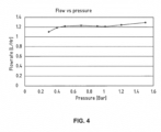
- Figure 4 shows a test result indicating that the present invention is able to function as pressure compensating strip 1, when said strip 1 is operatively connected to a drip irrigation hose 9.
- Different water pressures ranging from 0.3 to 1.5 Bar were used in the test, nevertheless, the resulting water flow rates (and outflow rate) are consistantly ranging between 1.1 to 1.3 liter per hour.
- This experimental result clearly proves that the labyrinth segment according to the present invention, in particular the regulating section that has a first type of profiles 24 and a second type of profiles 25 which function closely together but differently, is able to regulate and fine-tune water flow rate and its response to water pressure in a pressure compensating manner.
- At least one and “one or more” as used herein are interchangeable and relate to at least 1 and include 1, 2, 3, 4, 5, 6, 7, 8, 9 and more.
- irrigation hose is used herein generically to refer to any and all types of irrigation hose, whether seamless or formed with a welded seam, and independent of the structural material, the wall thickness or the degree of flexibility of the hose.
- profiles is used to refer to any barriers or partition walls having any particular shapes, which function to redirect the flow of water of a strip.
- labeling is used to refer to any flow restriction which is implemented as a long thin flow path, and most typically, as a meandering or zigzag flow pattern which allows water to flow throughout its entire length.
- the barriers between sections or legs of the path are referred to as “profiles”, “baffles” or “teeth”, and may be of any shape.
- elastomer is used herein in the description and claims to refer to any elastomeric material with sufficient flexibility to provide variable geometry flow regulation as taught in the context of the various embodiments below, and for which the elastic behavior is roughly repeatable.
- suitable elastomers include, but are not limited to, thermoplastic elastomers (TPE) such as SANTOPRENE ® and thermosetting polymers such as silicone.
- variable geometry flow path which serves to "regulate” the strip's water flow, and to provide a “compensated” strip (drip emitter).
- the terms “regulate” and “compensate” are used to refer to pressure responsive properties which at least partially compensate for variations in flow rate which would otherwise result from variations in the pressure within the irrigation hose.
Landscapes
- Life Sciences & Earth Sciences (AREA)
- Soil Sciences (AREA)
- Engineering & Computer Science (AREA)
- Water Supply & Treatment (AREA)
- Environmental Sciences (AREA)
- Rigid Pipes And Flexible Pipes (AREA)
- Nozzles (AREA)
- Infusion, Injection, And Reservoir Apparatuses (AREA)
Description
- The present invention relates to a continuous-type emitter for distributing water in a constant flow rate. In particular, the present invention provides means for water distribution by using a pressure compensating strip such as a continuouos emitter having a first profiles and a second profiles in a regulating section, thus allows for excellent fine-tuning of water flow rate and water pressure regulation.
- There are several types of irrigation systems widely used nowadays, depending on how the water is distributed throughout the field. Some common types of irrigation systems include, for example, surface irrigation, sprinkler irrigation and localized irrigation. In surface irrigation, water is distributed over and across land by gravity, and no mechanical pump involved. In sprinkler irrigation, water is distributed by overhead high-pressure sprinklers or guns from a central location in the field or from sprinklers on moving platforms.
- These systems have numerous shortcomings, including inefficient use of water and fertilizers, poor water distribution and poor uniformity of water application on steep or uneven terrain. In view of these shortcomings, localized irrigation has been developed, where water is distributed under low pressure, through a piped network and applied to each plant.
- Drip irrigation is a type of localized irrigation in which drops of water are delivered at or near the root of plants. In this type of irrigation, evaporation and runoff are minimized. A type of discrete emitter has been widely used in the drip irrigation system. However, such discrete emitter often consists of multiple parts, thus entails higher production cost, and therefore is less favorable in some instances due to economical reasons.
- Discrete emitters are commonly being used when a larger distance of water outlets are required, for instance a water outlet in about every 20cm or more for each segment water outlet. In this case, discrete emitters are more economically to be used compared to a continuous emitter. When water outlets are needed to be repeated in a shorter distance, for example less than every 20 cm, an elongated emitter is advantageuously a more favorable option.
- On another hand, some types of continuous emitter may consist of flexible tunnel-like emitter. Said tunnel-like emitter reduces water pressure (and hence water outflow rate) when water pressure of the hose is high. However, such type of flexible emitters face problems of higher fluctuation of water outflow, as water could bypass the tunnel-like emitter. Fine-tuning of the water outflow and/or water pressure thus fails to be realised in such kind of continuous emitter.
-
US 2003/150940 A1 andUS 6 382 530 B1 disclose relevant background art. - Furthermore, a lower cost of production and an easier production of a pressure compensating elongated flat sheet in a drip irrigation hose is also needed.
- Therefore, there remains a need to create a new, easier production, low cost, elongated-typed emitter such as a strip to emit water in an even shorter distance while able to maintain water pressure and/or water flow rate over a wide distance. Furthermore, water pressure in the drip irrigation hose that is better fine-tuned remained a challenge to be realised.
- The inventors of the present invention have surprisingly found out that the above-formulated need can be met by creating a specially-designed strip that is pressure-compensated, elastic, able to fine-tune water flow rate and regulate water pressure as defined in
claim 1. The strip is provided to be able to simultaneously response, regulate and reduce water flow rate and/or water pressure thanks to an array of specially designed profiles in a regulating section of the strip as claimed. This advantageously allows for a lower cost of production, shorter labyrinth segment, hence allowing for more repetitive labyrinth segments and more water outlets within a shorter distance. Hence, water is able to be distributed through outlets on the drip irrigation hose in a shorter distance, for example, less than about 10 cm, or even less than 5 cm without affecting the water flow rate of the pressure compensating strip. Furthermore, water pressure and water outflow can be better fine-tuned thanks to the different profiles provided in the regulating section of the strip, as water flows through the entire length of labyrinth segment of the strip. Under higher water pressure condition, certain profiles are pushed towards the hose, thereby creating additional barrier within the labyrinth. This enables water pressure to be regulated in an optimal condtion, allowing fine-tuning of water outflow condition and water pressure in the strip. - In a first aspect, the present invention therefore relates to a strip for distributing water, said strip has a repetitive labyrinth segment, wherein a plurality of profiles are provided to the base of the strip, said labyrinth segment comprises: a water input section; a regulating section arranged downstream from the water input section, wherein said regulating section is provided to regulate water flow rate of the strip in response to water pressure of a hose; a discharge section arranged downstream from the regulating section, wherein said discharge section is provided with deflection-resistant reinforcement means. In addition to the advantages described above, the discharge section of the strip according to the present invention allows water to be evenly distributed in a controllable manner, as reinforcement means is provided to reduce frequency of deflection caused by water pressures which exits from the outlets.
- In a second aspect, the present invention relates to a pressure compensating drip irrigation hose comprising the aforementioned strip as described herein.
- According to a variant of the present invention, said strip is made of at least one elastomeric material. This advantageously allows for not only a lower cost of production and easier production, it allows for the drip irrigation hose to be arranged in all possible positions without hindering the flexibility of the hose.
- According to yet another variant of the present invention, the water input section is provided with a filter means. This advantageously allows for water to be filtered before entering into the regulating section.
- According to another variant of the present invention, the distance between the profiles in the input section are less than the distance between the profiles in the regulating section. This advantageously prevents particles larger than the gap between profiles in the water input section to be entered into the regulating section of the strip.
- According to the claimed present invention, the strip has two rails, forming side walls of the strip. The rails could exist in both the regulating section and the discharge section. This allows water to enter into the strip only through the water input section which has a filter means to filter out certain particles having diameter larger than the gap between profiles of water input section. The filtered water then flows along the labyrinth segment.
- According to the claimed present invention, said profiles in the regulating section comprises a first profile, and a second profile, wherein the first profiles are a rectangular-shaped block whereas the second profiles have a wedge shape. The first profiles, and the second profile in the regulating section have a barrier-like partition structure extended from the rails of the strip. The first profiles are advantageusly designed to set a limitation of a fixed volume of water flowing in the strip. This allows for a certain predetermined water flow rate and/or water pressure flowing in the strip. This prevents voids of the strip to collapse under situation where water pressure is extremely high in the hose. The second profiles of the regulating section are advantageously designed to be able to response, regulate and reduce water pressure and/or water flow rate of the strip according to water pressure within the drip irrigation hose. Importantly, in the present invention, water flows along the entire labyrinth segment of the strip. On one hand, the first profiles allow for a maximum volume of water flowing in the strip; on another hand, the second profiles fine-tune water pressure and/or water flow rate of the strip depending on the water pressure of the hose. Such combination of at least two different profiles in the regulating section of the strip thus allows an optimal pressure compensating drip irrigation hose to be realised.
- According to one preferred embodiment of the present invention, the entire top surface of the first profiles opposite to the base of the strip are connected to an inner part of a hose. This allows said type of first profiles to be fixed permanently between the strip and the hose, thus allowing a fixed volume of water flowing within the strip.
- According to the claimed present invention, the profiles in the regulating section are provided in an alternative and regular or irregular fashion throughout the repeated labyrinth segment. In order to allow water flow rate of the strip and its response to water pressure of the hose to be regulated in a wider range, higher number of the second profiles having a wedge shape than the first profiles could be arranged in the regulating section of the strip. Contrary, as an example, in order to better fine-tune water outflow (water flow rate in the strip) and its response to the water pressure of the hose, less number of the second profiles than the first profiles can be used to achieve the aforementioned goal.
- According to one preferred embodiment of the present invention, the discharge section is provided with interconnected reinforcements to increase the resistance of deflection.
- According to another preferred embodiment of the present invention, the interconnected reinforcements are provided at the base of the strip. This fortifies said section, allowing for a stronger structure.
- According to one preferred embodiment of the present invention, the interconnected reinforcements have height less than the top surface of the rails of the strip so that their influence on disturbing water flow rate is minimised.
- According to yet another preferred embodiment of the present invention, the strip is provided at an inner surface of the drip irrigation hose.
- According to one preferred embodiment of the present invention, the strip is made up of material less stiff than the drip irrigation hose so that the flexibility of the hose is not affected by the strip operatively connected within.
- According to one preferred embodiment of the present invention, at least one outlet of the hose is provided at the discharge section of the strip. This allows for instaneously water outflow.
- According to the present invention, the outlet is an open-end outlet or a slit. Both open end outlet and slit outlet allow water to be emitted easily Furthermore, slit outlets further prevent the roots of the plants from growing into the drip irrigation hose.
- Thanks to the present uniquely designed strip having a water input section, a regulating section and a discharge section which form a labyrinth segment, the labyrinth segment of the strip according to the present invention is able to be designed in various length, for instance less than 10cm. It is possible to be less than 8 cm. It is also designed for less than 5 cm without affecting the functionality of the pressure compesating strip and its water flow rate as well as fine-tuning its response to water pressure of the hose.
- The drawings are not necessarily drawn to scale, emphasis instead is generally being placed upon illustrating the principles of various embodiments. In the following description, various embodiments of the invention are described with reference to the following drawings.
-
Figure 1 : One embodiment of a strip having a repetitive labyrinth not according to the present invention. -
Figure 2A : Enlarged top plan of a water input section as shown inFig. 1 defined byreference number 3 and 3'. -
Figure 2B : Enlarged top plan of a regulating section as shown inFig. 1 defined byreference number 4 and 4'. -
Figure 2C : Enlarged top plan of a discharge section as shown inFig. 1 defined byreference number 5 and 5'. -
Figure 3A : Scaled-up bird eye's view of the regulating section having first profiles and second profiles, and two rails forming side walls of the strip according to the present invention. -
Figure 3B : Longitudinal-sectional view taken at regulating section showing the difference of heights between the first profiles and the second profiles. -
Figure 4 : Graph showing the relation between water flow at different water pressure according to the present invention. - In order to overcome the above described drawbacks of emitters in the art, a new strip (1) connected to a drip irrigation hose (9) for distributing water is espoused. Said strip (1) comprised of a repetitive labyrinth segment (2, 2'), the labyrinth segment has a water input section (3, 3'), followed by a regulating section (4, 4') and subsequently a discharge section (5, 5'), wherein a plurality of profiles (21, 24, 25, 26) are provided to the base (15) of the strip (1), wherein said regulating section (4, 4') is provided to regulate water flow rate of the strip (1) in response of water pressure of a hose. It also simultaneously regulates and responses to water pressure within a certain predetermined water pressure level; a discharge section (5, 5') arranged downstream from the regulating section (4, 4'), wherein said discharge section is provided with deflection-resistant reinforcement means.
-
Figure 1 shows a schematic representation of an exemplary embodiment of the strip not according to the present invention. Thestrip 1 has arepetitive labyrinth segment water input section 3, 3'; aregulating section 4, 4'; and adischarge section 5, 5'. Thestrip 1 can be made up of any elastomeric materials such as thermoplastic elastomeric synthetic polymer or natural rubber including commonly used polymers such as Polybutadiene, EVA and etc. -
Figure 2A-C show enlarged top plan of a water input section (Fig. 2A ), a regulating section (Fig. 2B ) and a discharge section (Fig. 2C ). As can be seen inFig. 2A , a plurality ofprofiles 21 are provided at the base (15) of thestrip 1. In this particular example, two rows of closely-alignedprofiles 21 are arranged at thewater input section 3, 3'. A gap GPI exists between each profiles 21 of the water input section. Theprofiles 21 in thewater input section 3 serves as filters to filter out any particles larger than the gap GPI between theprofiles 21. Similarly, another gap GPII exists between afirst profiles 24 and asecond profiles 25 in the regulating section 4 (Fig. 3B ). The gap GPI betweenprofiles 21 in thewater input section 2 is less than the gap GPII between the first andsecond profiles regulating section 3. Therefore, a filter mechanism is provided through the arrangement of various types ofprofiles - As can be clearly seen in the
Figures 2B and 2C , tworails 22 are located at both sides of thestrip 1, namely at theregulating section 4 and at thedischarge section 5, but is absent at thewater input section 3. As a consequences, water from the drip irrigation hose is capable to first enters through thewater input section 3, 3' of each of the repeatedlabyrinth segment 2, 2', followed by entering theregulating section 4, 4' and finally thedischarge section 5, 5' which is arranged downstream from the regulating section. At least oneoutlet opening 12 is provided at thedrip irrigation hose 9 that sits on top of thedischarge section 5, 5'. -
Figure 3A shows a scaled-up bird eye's view of aregulating section 4 having tworails 22 according to the present invention. Two different types ofprofiles profiles base 15 of thestrip 1. The first profiles 24, which are rectangular shape partitions, have the same height across itstop surface 23 as to the top surface of therails 22. The second profiles 25, which are wedge-shape partitions, have gradually reducing height moving to the centre of thestrip 1 compared to the side connected to therails 22. - The second profiles 25 having a wedge-shaped profile (and having height less than the
top surface 23 of therail 22 of the strip 1) are being sandwiched by twofirst profiles 24 that have a rectangular-shaped profile (across the top surface opposite to the base 15 having the same height as to thetop surface 23 of therail 22 of the strip 1). This arrangement is repeated in a regular (consistent) manner. However, an irregular arrangement with different proportion offirst profiles 24 andsecond profiles 25 can also be realised for different purposes. - The first profiles 24 (or so-called a fixed profile) serve to limit a certain maximum volume of water flowing in the
strip 1. In other words, water pressure of the drip irrigation hose does not affect the reaction of the first profiles 24. On another hand, the top surface of the second profiles 25 (or so-called a flexible profile) opposite to thebase 15 of thestrip 1 are not connected to thedrip irrigation hose 9, hence thesecond profiles 25 are able to response according to the water pressure of thedrip irrigation hose 9 in order to regulate water flow rate as well as water pressure of thestrip 1, thanks to its gradually decreasing height towards the centre of the strip. - By employing this mix arrangement of two different types of
profiles strip 1, water pressure and water flow rate are able to be regulated consistently in a precise manner. Also fine-tuning of the water outflow rate as well as water pressure of the strip can be achieved thanks to theseprofiles strip 1. -
Figure 3B shows a longitudinal sectional view of the regulating section (4, 4') of thestrip 1. As can be clearly seen, thefirst profiles 24 are connected between the base 15 of thestrip 1 and an inner surface of thedrip irrigation hose 9. The top surface of thesecond profiles 25 opposite to thebase 15 of thestrip 1 are not connected to an inner surface of thesrip irrigation hose 9. A distance M thus exists. When water pressure ofdrip irrigation hose 9 is low, the second profiles are not being pushed towards the inner surface of the drop irrigation hose. To the contrary, when water pressure of thedrip irrigation hose 9 increases, thesecond profiles 25 are being pushed towards the inner surface of thedrip irrigation hose 9, thus closes the gap M, creating additional labyrinth paths within the existing labyrinth. This allows for a fine-tuned and more consistent method of regulating water outflow rate of the strip. - It is to be understood that different arrangements of the first and second profiles can be arranged in order to give a certain water pressure as well as water outflow rate of the
strip 1. Hence, it could be easily comprehended that the more number of thesecond profiles 25 are being provided than thefirst profiles 24, the larger amount of water would be able to flow within thestrip 1, thus a larger response to the water pressure within the drip irrigation hose could be regulated. - Moreover, a further different type of profiles 27, 28 (third, fourth...) in the
regulating section 4, 4' of the strip may also exist in theregulating section 4 for a particular reason, for instance to further distribute or lower water pressure, reinforce thestrip 1 in order to reduce deflection forces resulting from water droplets exiting fromoutlets 12 of the drip irrigation hose or to maintain a certain water pressure within thestrip 1. -
Figure 4 shows a test result indicating that the present invention is able to function aspressure compensating strip 1, when saidstrip 1 is operatively connected to adrip irrigation hose 9. Different water pressures ranging from 0.3 to 1.5 Bar were used in the test, nevertheless, the resulting water flow rates (and outflow rate) are consistantly ranging between 1.1 to 1.3 liter per hour. This experimental result clearly proves that the labyrinth segment according to the present invention, in particular the regulating section that has a first type ofprofiles 24 and a second type ofprofiles 25 which function closely together but differently, is able to regulate and fine-tune water flow rate and its response to water pressure in a pressure compensating manner. - This test result indicates that the
profiles strip 1 interdisposed from each other in an alternative, regular or irregular manner, repetitively, work as if said profiles are being arranged separately in two different sections. Hence, it is apparent that present invention is superior in the sense that a unified section of regulating section according to the present invention is able to regulate water flow rate in an unexpected excellent manner. Nevertheless, shorter labyrinth segment, which is required sometimes to irrigate closely located vegetations, can be achieved by using the present invention. - By "about" in relation to a given numerical value such as length, distance, amount or a period of time, it is meant to include numerical values within 10% of the specified value.
- The terms "at least one" and "one or more" as used herein are interchangeable and relate to at least 1 and include 1, 2, 3, 4, 5, 6, 7, 8, 9 and more.
- The term "irrigation hose" is used herein generically to refer to any and all types of irrigation hose, whether seamless or formed with a welded seam, and independent of the structural material, the wall thickness or the degree of flexibility of the hose.
- The term "profiles" is used to refer to any barriers or partition walls having any particular shapes, which function to redirect the flow of water of a strip.
- The term "labyrinth" is used to refer to any flow restriction which is implemented as a long thin flow path, and most typically, as a meandering or zigzag flow pattern which allows water to flow throughout its entire length. The barriers between sections or legs of the path are referred to as "profiles", "baffles" or "teeth", and may be of any shape.
- The term "elastomer" is used herein in the description and claims to refer to any elastomeric material with sufficient flexibility to provide variable geometry flow regulation as taught in the context of the various embodiments below, and for which the elastic behavior is roughly repeatable. Preferred examples of suitable elastomers include, but are not limited to, thermoplastic elastomers (TPE) such as SANTOPRENE® and thermosetting polymers such as silicone.
- Reference is made to a variable geometry flow path which serves to "regulate" the strip's water flow, and to provide a "compensated" strip (drip emitter). In this context, the terms "regulate" and "compensate" are used to refer to pressure responsive properties which at least partially compensate for variations in flow rate which would otherwise result from variations in the pressure within the irrigation hose.
- Other embodiments are within the following claims and non- limiting examples. It is to be understood that these examples are for illustrative purposes only and are not to be construed to limit the scope of the present invention, which is defined by the appended claims.
Claims (12)
- A strip (1) for being connected to a drip irrigation hose for distributing water having a repetitive labyrinth segment (2, 2'), wherein a plurality of profiles (21, 24, 25, 26) are provided to a base (15) of the strip (1), said labyrinth segment (2, 2') comprises:a water input section (3, 3');a regulating section (4, 4') arranged downstream from the water input section, wherein said regulating section is provided to regulate water flow rate of the strip (1) in response to water pressure of said hose (9); anda discharge section (5, 5') arranged downstream from the regulating section (4, 4'), wherein said discharge section is provided with deflection-resistant reinforcement means (26);characterized in that the regulating section (4,4') has two rails (22) forming side walls of the strip and comprises two different types of profiles (24, 25) which are provided at the base (15) of the strip (1), wherein the first profiles (24) which are rectangular shape partitions have the same height across its top surface (23) as to the top surface of the rails (22), wherein the second profiles (25) which are wedge-shape partitions have gradually reducing height moving to the centre of the strip (1) compared to the side connected to the rails (22), wherein said first and second profiles (24, 25) are provided in an alternative, and regular or irregular fashion throughout the regulating section, such that said regulating section (4,4') simultaneously regulates and responses to the water pressure of said hose.
- The strip (1) according to claim 1, wherein the water input section (3, 3') are provided with a filter means.
- The strip (1) according to claim 1 or claim 2, wherein the distance between the profiles (21) in the input section are less than the distance between the profiles (24, 25) in the regulating section.
- The strip (1) according to claim 1, wherein the entire top surface of the first profiles (24) opposite to the base (15) are connected to an inner part of a hose (9).
- The strip (1) according to claim 1, wherein the profiles (26) in the discharge section (5, 5') is provided with interconnected reinforcements (26) to increase the resistance of deflection.
- The strip (1) according to claim 5, wherein the interconnected reinforcements (26) are provided at the base of the strip (15).
- The strip (1) according to claim 1 and claim 5, wherein the interconnected reinforcements (26) have a height less than the top surface (23) of the rail (22) of the strip (1).
- A pressure compensating drip irrigation hose (9) comprising said strip (1) according to any one of the claims 1-7.
- The pressure compensating drip irrigation hose (9) according to claim 8, wherein the strip (1) is provided at an inner surface of the drip irrigation surface.
- The pressure compensating drip irrigation hose (9) according to claim 8 or claim 9, wherein the strip (1) is made up of material less stiff than the pressure compensating drip irrigation hose (9).
- The pressure compensating drip irrigation hose (9) according to any one of the preceding claims 9-10, wherein at least one outlet (12) of the hose (9) is provided at the discharge section (C, F) of the strip (1).
- The pressure compensating drip irrigation hose according to the claim 11, wherein the outlet (12) is an open-end outlet or a slit.
Priority Applications (14)
| Application Number | Priority Date | Filing Date | Title |
|---|---|---|---|
| ES15180002T ES2987438T3 (en) | 2015-08-06 | 2015-08-06 | Drip irrigation hose with strip |
| RS20240951A RS65919B1 (en) | 2015-08-06 | 2015-08-06 | A drip irrigation hose with strip |
| EP15180002.6A EP3127424B1 (en) | 2015-08-06 | 2015-08-06 | A drip irrigation hose with strip |
| PT151800026T PT3127424T (en) | 2015-08-06 | 2015-08-06 | A drip irrigation hose with strip |
| US15/750,194 US10716268B2 (en) | 2015-08-06 | 2016-08-03 | Drip irrigation hose with strip |
| RU2018107559A RU2723041C2 (en) | 2015-08-06 | 2016-08-03 | Drip irrigation hose with band |
| MX2018001299A MX2018001299A (en) | 2015-08-06 | 2016-08-03 | A drip irrigation hose with strip. |
| BR112018001071A BR112018001071A2 (en) | 2015-08-06 | 2016-08-03 | strip drip irrigation hose |
| CN201680046229.6A CN107920478B (en) | 2015-08-06 | 2016-08-03 | Drip hose with strap |
| PE2018000112A PE20180792A1 (en) | 2015-08-06 | 2016-08-03 | ONE BAND DRIP IRRIGATION HOSE |
| MA41877A MA41877A1 (en) | 2015-08-06 | 2016-08-03 | Drip irrigation hose with tape |
| TNP/2018/000025A TN2018000025A1 (en) | 2015-08-06 | 2016-08-03 | A drip irrigation hose with strip |
| PCT/EP2016/068572 WO2017021462A1 (en) | 2015-08-06 | 2016-08-03 | A drip irrigation hose with strip |
| IL257215A IL257215B (en) | 2015-08-06 | 2016-08-03 | A drip irrigation hose that includes a strap |
Applications Claiming Priority (1)
| Application Number | Priority Date | Filing Date | Title |
|---|---|---|---|
| EP15180002.6A EP3127424B1 (en) | 2015-08-06 | 2015-08-06 | A drip irrigation hose with strip |
Publications (2)
| Publication Number | Publication Date |
|---|---|
| EP3127424A1 EP3127424A1 (en) | 2017-02-08 |
| EP3127424B1 true EP3127424B1 (en) | 2024-07-31 |
Family
ID=53783588
Family Applications (1)
| Application Number | Title | Priority Date | Filing Date |
|---|---|---|---|
| EP15180002.6A Active EP3127424B1 (en) | 2015-08-06 | 2015-08-06 | A drip irrigation hose with strip |
Country Status (14)
| Country | Link |
|---|---|
| US (1) | US10716268B2 (en) |
| EP (1) | EP3127424B1 (en) |
| CN (1) | CN107920478B (en) |
| BR (1) | BR112018001071A2 (en) |
| ES (1) | ES2987438T3 (en) |
| IL (1) | IL257215B (en) |
| MA (1) | MA41877A1 (en) |
| MX (1) | MX2018001299A (en) |
| PE (1) | PE20180792A1 (en) |
| PT (1) | PT3127424T (en) |
| RS (1) | RS65919B1 (en) |
| RU (1) | RU2723041C2 (en) |
| TN (1) | TN2018000025A1 (en) |
| WO (1) | WO2017021462A1 (en) |
Families Citing this family (9)
| Publication number | Priority date | Publication date | Assignee | Title |
|---|---|---|---|---|
| US10330559B2 (en) | 2014-09-11 | 2019-06-25 | Rain Bird Corporation | Methods and apparatus for checking emitter bonds in an irrigation drip line |
| US11051466B2 (en) | 2017-01-27 | 2021-07-06 | Rain Bird Corporation | Pressure compensation members, emitters, drip line and methods relating to same |
| USD883048S1 (en) | 2017-12-12 | 2020-05-05 | Rain Bird Corporation | Emitter part |
| US11985924B2 (en) | 2018-06-11 | 2024-05-21 | Rain Bird Corporation | Emitter outlet, emitter, drip line and methods relating to same |
| US11497178B2 (en) | 2019-06-14 | 2022-11-15 | The Toro Company | Drip irrigation emitter with optimized clog resistance |
| CN112075331B (en) * | 2019-06-14 | 2023-03-24 | 托罗公司(美国) | Track tuning pressure response irrigation emitter |
| US12207599B2 (en) | 2021-10-12 | 2025-01-28 | Rain Bird Corporation | Emitter coupler and irrigation system |
| CN113841590B (en) * | 2021-10-27 | 2023-03-31 | 三峡大学 | External patch type variable flow channel anti-blocking drip irrigation tape and anti-blocking drip irrigation method |
| CN117837473B (en) * | 2024-02-26 | 2026-04-03 | 清华大学 | Labyrinth flow channels and drip irrigation emitters |
Citations (1)
| Publication number | Priority date | Publication date | Assignee | Title |
|---|---|---|---|---|
| US6371390B1 (en) * | 2000-08-21 | 2002-04-16 | Amir Cohen | Drip irrigation hose and method of making same |
Family Cites Families (10)
| Publication number | Priority date | Publication date | Assignee | Title |
|---|---|---|---|---|
| SU471094A1 (en) * | 1973-08-21 | 1975-05-25 | Украинский Научно-Исследовательский Институт Гидротехники И Мелиорации | Water outlet |
| US5400973A (en) * | 1993-07-30 | 1995-03-28 | Cohen; Amir | Pressure responsive regulated flow restrictor useful for drip irrigation |
| US6382530B1 (en) * | 2000-07-10 | 2002-05-07 | Nelson Irrigation Corporation | Pressure compensating drip tape |
| US6886761B2 (en) * | 2000-08-21 | 2005-05-03 | Amir Cohen | Drip irrigation hose and method and apparatus for making same |
| US6736337B2 (en) * | 2002-02-08 | 2004-05-18 | The Toro Company | Pressure compensating drip irrigation hose |
| IL171482A (en) * | 2005-10-19 | 2014-12-31 | Zvi Einav | Dropper with independent runoff valve |
| US7735758B2 (en) * | 2006-09-18 | 2010-06-15 | Amir Cohen | Drip irrigation hoses of the labyrinth type and flow-control elements for producing such hoses |
| US8763934B2 (en) * | 2010-02-03 | 2014-07-01 | Parixit Amrutbhai Patel | Non pressure compensated drip irrigation emitter with multiflow facility |
| US9485923B2 (en) * | 2012-03-26 | 2016-11-08 | Rain Bird Corporation | Elastomeric emitter and methods relating to same |
| CN203400801U (en) * | 2013-08-12 | 2014-01-22 | 保定丰霸现代农业设施有限公司 | Pressure compensation type ageing-resistant drip tape |
-
2015
- 2015-08-06 EP EP15180002.6A patent/EP3127424B1/en active Active
- 2015-08-06 PT PT151800026T patent/PT3127424T/en unknown
- 2015-08-06 RS RS20240951A patent/RS65919B1/en unknown
- 2015-08-06 ES ES15180002T patent/ES2987438T3/en active Active
-
2016
- 2016-08-03 WO PCT/EP2016/068572 patent/WO2017021462A1/en not_active Ceased
- 2016-08-03 CN CN201680046229.6A patent/CN107920478B/en active Active
- 2016-08-03 RU RU2018107559A patent/RU2723041C2/en active
- 2016-08-03 IL IL257215A patent/IL257215B/en unknown
- 2016-08-03 MX MX2018001299A patent/MX2018001299A/en unknown
- 2016-08-03 MA MA41877A patent/MA41877A1/en unknown
- 2016-08-03 BR BR112018001071A patent/BR112018001071A2/en not_active Application Discontinuation
- 2016-08-03 TN TNP/2018/000025A patent/TN2018000025A1/en unknown
- 2016-08-03 PE PE2018000112A patent/PE20180792A1/en unknown
- 2016-08-03 US US15/750,194 patent/US10716268B2/en active Active
Patent Citations (1)
| Publication number | Priority date | Publication date | Assignee | Title |
|---|---|---|---|---|
| US6371390B1 (en) * | 2000-08-21 | 2002-04-16 | Amir Cohen | Drip irrigation hose and method of making same |
Also Published As
| Publication number | Publication date |
|---|---|
| CN107920478B (en) | 2021-08-13 |
| ES2987438T3 (en) | 2024-11-14 |
| PE20180792A1 (en) | 2018-05-08 |
| US10716268B2 (en) | 2020-07-21 |
| WO2017021462A1 (en) | 2017-02-09 |
| CN107920478A (en) | 2018-04-17 |
| TN2018000025A1 (en) | 2019-07-08 |
| IL257215B (en) | 2022-07-01 |
| EP3127424A1 (en) | 2017-02-08 |
| RU2018107559A3 (en) | 2019-11-14 |
| US20180220601A1 (en) | 2018-08-09 |
| MX2018001299A (en) | 2018-08-15 |
| IL257215A (en) | 2018-03-29 |
| MA41877A1 (en) | 2018-07-31 |
| RU2018107559A (en) | 2019-09-09 |
| RU2723041C2 (en) | 2020-06-08 |
| BR112018001071A2 (en) | 2018-09-11 |
| PT3127424T (en) | 2024-09-02 |
| RS65919B1 (en) | 2024-10-31 |
Similar Documents
| Publication | Publication Date | Title |
|---|---|---|
| US10716268B2 (en) | Drip irrigation hose with strip | |
| US6736337B2 (en) | Pressure compensating drip irrigation hose | |
| US11185021B2 (en) | Elastomeric emitter and methods relating to same | |
| US9485923B2 (en) | Elastomeric emitter and methods relating to same | |
| US9807948B2 (en) | Drip irrigation tube with metering elements inserted therein | |
| US8663525B2 (en) | Internally pressure compensated non-clogging drip emitter | |
| US8372326B2 (en) | Pressure compensated non-clogging drip emitter | |
| JP6541220B2 (en) | Emitter and drip irrigation tube | |
| US20230225265A1 (en) | Emitter Outlet, Emitter, Drip Line and Methods Relating To Same | |
| BR112016002731B1 (en) | elastomeric emitter and methods related to it | |
| EP3277077B1 (en) | Spray nozzle assembly with expanded pressure responsive liquid flow rate control | |
| EP0538242B1 (en) | Drip irrigation system employing adjacently arranged flow-restricting passages | |
| JP6251186B2 (en) | Drip irrigation dripper and drip irrigation apparatus provided with the same | |
| US20080017729A1 (en) | High volume dripping hoses | |
| EP0278049B1 (en) | Drip irrigation system employing adjacently arranged flow-restricting passages | |
| RU2311758C1 (en) | Drop-forming apparatus |
Legal Events
| Date | Code | Title | Description |
|---|---|---|---|
| PUAI | Public reference made under article 153(3) epc to a published international application that has entered the european phase |
Free format text: ORIGINAL CODE: 0009012 |
|
| STAA | Information on the status of an ep patent application or granted ep patent |
Free format text: STATUS: THE APPLICATION HAS BEEN PUBLISHED |
|
| AK | Designated contracting states |
Kind code of ref document: A1 Designated state(s): AL AT BE BG CH CY CZ DE DK EE ES FI FR GB GR HR HU IE IS IT LI LT LU LV MC MK MT NL NO PL PT RO RS SE SI SK SM TR |
|
| AX | Request for extension of the european patent |
Extension state: BA ME |
|
| STAA | Information on the status of an ep patent application or granted ep patent |
Free format text: STATUS: REQUEST FOR EXAMINATION WAS MADE |
|
| 17P | Request for examination filed |
Effective date: 20170629 |
|
| RBV | Designated contracting states (corrected) |
Designated state(s): AL AT BE BG CH CY CZ DE DK EE ES FI FR GB GR HR HU IE IS IT LI LT LU LV MC MK MT NL NO PL PT RO RS SE SI SK SM TR |
|
| STAA | Information on the status of an ep patent application or granted ep patent |
Free format text: STATUS: EXAMINATION IS IN PROGRESS |
|
| 17Q | First examination report despatched |
Effective date: 20210602 |
|
| P01 | Opt-out of the competence of the unified patent court (upc) registered |
Effective date: 20230630 |
|
| GRAP | Despatch of communication of intention to grant a patent |
Free format text: ORIGINAL CODE: EPIDOSNIGR1 |
|
| STAA | Information on the status of an ep patent application or granted ep patent |
Free format text: STATUS: GRANT OF PATENT IS INTENDED |
|
| INTG | Intention to grant announced |
Effective date: 20240327 |
|
| GRAS | Grant fee paid |
Free format text: ORIGINAL CODE: EPIDOSNIGR3 |
|
| GRAA | (expected) grant |
Free format text: ORIGINAL CODE: 0009210 |
|
| STAA | Information on the status of an ep patent application or granted ep patent |
Free format text: STATUS: THE PATENT HAS BEEN GRANTED |
|
| AK | Designated contracting states |
Kind code of ref document: B1 Designated state(s): AL AT BE BG CH CY CZ DE DK EE ES FI FR GB GR HR HU IE IS IT LI LT LU LV MC MK MT NL NO PL PT RO RS SE SI SK SM TR |
|
| REG | Reference to a national code |
Ref country code: CH Ref legal event code: EP Ref country code: GB Ref legal event code: FG4D |
|
| REG | Reference to a national code |
Ref country code: DE Ref legal event code: R096 Ref document number: 602015089364 Country of ref document: DE |
|
| REG | Reference to a national code |
Ref country code: IE Ref legal event code: FG4D |
|
| REG | Reference to a national code |
Ref country code: PT Ref legal event code: SC4A Ref document number: 3127424 Country of ref document: PT Date of ref document: 20240902 Kind code of ref document: T Free format text: AVAILABILITY OF NATIONAL TRANSLATION Effective date: 20240827 |
|
| REG | Reference to a national code |
Ref country code: NL Ref legal event code: FP |
|
| REG | Reference to a national code |
Ref country code: ES Ref legal event code: FG2A Ref document number: 2987438 Country of ref document: ES Kind code of ref document: T3 Effective date: 20241114 |
|
| REG | Reference to a national code |
Ref country code: LT Ref legal event code: MG9D |
|
| REG | Reference to a national code |
Ref country code: GR Ref legal event code: EP Ref document number: 20240402065 Country of ref document: GR Effective date: 20241111 |
|
| REG | Reference to a national code |
Ref country code: AT Ref legal event code: MK05 Ref document number: 1707540 Country of ref document: AT Kind code of ref document: T Effective date: 20240731 |
|
| PG25 | Lapsed in a contracting state [announced via postgrant information from national office to epo] |
Ref country code: NO Free format text: LAPSE BECAUSE OF FAILURE TO SUBMIT A TRANSLATION OF THE DESCRIPTION OR TO PAY THE FEE WITHIN THE PRESCRIBED TIME-LIMIT Effective date: 20241031 |
|
| PG25 | Lapsed in a contracting state [announced via postgrant information from national office to epo] |
Ref country code: FI Free format text: LAPSE BECAUSE OF FAILURE TO SUBMIT A TRANSLATION OF THE DESCRIPTION OR TO PAY THE FEE WITHIN THE PRESCRIBED TIME-LIMIT Effective date: 20240731 Ref country code: PL Free format text: LAPSE BECAUSE OF FAILURE TO SUBMIT A TRANSLATION OF THE DESCRIPTION OR TO PAY THE FEE WITHIN THE PRESCRIBED TIME-LIMIT Effective date: 20240731 |
|
| PG25 | Lapsed in a contracting state [announced via postgrant information from national office to epo] |
Ref country code: LV Free format text: LAPSE BECAUSE OF FAILURE TO SUBMIT A TRANSLATION OF THE DESCRIPTION OR TO PAY THE FEE WITHIN THE PRESCRIBED TIME-LIMIT Effective date: 20240731 |
|
| PG25 | Lapsed in a contracting state [announced via postgrant information from national office to epo] |
Ref country code: AT Free format text: LAPSE BECAUSE OF FAILURE TO SUBMIT A TRANSLATION OF THE DESCRIPTION OR TO PAY THE FEE WITHIN THE PRESCRIBED TIME-LIMIT Effective date: 20240731 Ref country code: IS Free format text: LAPSE BECAUSE OF FAILURE TO SUBMIT A TRANSLATION OF THE DESCRIPTION OR TO PAY THE FEE WITHIN THE PRESCRIBED TIME-LIMIT Effective date: 20241130 |
|
| PG25 | Lapsed in a contracting state [announced via postgrant information from national office to epo] |
Ref country code: HR Free format text: LAPSE BECAUSE OF FAILURE TO SUBMIT A TRANSLATION OF THE DESCRIPTION OR TO PAY THE FEE WITHIN THE PRESCRIBED TIME-LIMIT Effective date: 20240731 |
|
| PG25 | Lapsed in a contracting state [announced via postgrant information from national office to epo] |
Ref country code: PL Free format text: LAPSE BECAUSE OF FAILURE TO SUBMIT A TRANSLATION OF THE DESCRIPTION OR TO PAY THE FEE WITHIN THE PRESCRIBED TIME-LIMIT Effective date: 20240731 Ref country code: NO Free format text: LAPSE BECAUSE OF FAILURE TO SUBMIT A TRANSLATION OF THE DESCRIPTION OR TO PAY THE FEE WITHIN THE PRESCRIBED TIME-LIMIT Effective date: 20241031 Ref country code: LV Free format text: LAPSE BECAUSE OF FAILURE TO SUBMIT A TRANSLATION OF THE DESCRIPTION OR TO PAY THE FEE WITHIN THE PRESCRIBED TIME-LIMIT Effective date: 20240731 Ref country code: IS Free format text: LAPSE BECAUSE OF FAILURE TO SUBMIT A TRANSLATION OF THE DESCRIPTION OR TO PAY THE FEE WITHIN THE PRESCRIBED TIME-LIMIT Effective date: 20241130 Ref country code: HR Free format text: LAPSE BECAUSE OF FAILURE TO SUBMIT A TRANSLATION OF THE DESCRIPTION OR TO PAY THE FEE WITHIN THE PRESCRIBED TIME-LIMIT Effective date: 20240731 Ref country code: FI Free format text: LAPSE BECAUSE OF FAILURE TO SUBMIT A TRANSLATION OF THE DESCRIPTION OR TO PAY THE FEE WITHIN THE PRESCRIBED TIME-LIMIT Effective date: 20240731 Ref country code: AT Free format text: LAPSE BECAUSE OF FAILURE TO SUBMIT A TRANSLATION OF THE DESCRIPTION OR TO PAY THE FEE WITHIN THE PRESCRIBED TIME-LIMIT Effective date: 20240731 |
|
| PG25 | Lapsed in a contracting state [announced via postgrant information from national office to epo] |
Ref country code: DK Free format text: LAPSE BECAUSE OF FAILURE TO SUBMIT A TRANSLATION OF THE DESCRIPTION OR TO PAY THE FEE WITHIN THE PRESCRIBED TIME-LIMIT Effective date: 20240731 Ref country code: SM Free format text: LAPSE BECAUSE OF FAILURE TO SUBMIT A TRANSLATION OF THE DESCRIPTION OR TO PAY THE FEE WITHIN THE PRESCRIBED TIME-LIMIT Effective date: 20240731 |
|
| PG25 | Lapsed in a contracting state [announced via postgrant information from national office to epo] |
Ref country code: LU Free format text: LAPSE BECAUSE OF NON-PAYMENT OF DUE FEES Effective date: 20240806 |
|
| PG25 | Lapsed in a contracting state [announced via postgrant information from national office to epo] |
Ref country code: EE Free format text: LAPSE BECAUSE OF FAILURE TO SUBMIT A TRANSLATION OF THE DESCRIPTION OR TO PAY THE FEE WITHIN THE PRESCRIBED TIME-LIMIT Effective date: 20240731 Ref country code: MC Free format text: LAPSE BECAUSE OF FAILURE TO SUBMIT A TRANSLATION OF THE DESCRIPTION OR TO PAY THE FEE WITHIN THE PRESCRIBED TIME-LIMIT Effective date: 20240731 |
|
| PG25 | Lapsed in a contracting state [announced via postgrant information from national office to epo] |
Ref country code: CZ Free format text: LAPSE BECAUSE OF FAILURE TO SUBMIT A TRANSLATION OF THE DESCRIPTION OR TO PAY THE FEE WITHIN THE PRESCRIBED TIME-LIMIT Effective date: 20240731 |
|
| PG25 | Lapsed in a contracting state [announced via postgrant information from national office to epo] |
Ref country code: SK Free format text: LAPSE BECAUSE OF FAILURE TO SUBMIT A TRANSLATION OF THE DESCRIPTION OR TO PAY THE FEE WITHIN THE PRESCRIBED TIME-LIMIT Effective date: 20240731 |
|
| REG | Reference to a national code |
Ref country code: DE Ref legal event code: R097 Ref document number: 602015089364 Country of ref document: DE |
|
| PLBE | No opposition filed within time limit |
Free format text: ORIGINAL CODE: 0009261 |
|
| STAA | Information on the status of an ep patent application or granted ep patent |
Free format text: STATUS: NO OPPOSITION FILED WITHIN TIME LIMIT |
|
| GBPC | Gb: european patent ceased through non-payment of renewal fee |
Effective date: 20241031 |
|
| REG | Reference to a national code |
Ref country code: BE Ref legal event code: MM Effective date: 20240831 |
|
| 26N | No opposition filed |
Effective date: 20250501 |
|
| PG25 | Lapsed in a contracting state [announced via postgrant information from national office to epo] |
Ref country code: GB Free format text: LAPSE BECAUSE OF NON-PAYMENT OF DUE FEES Effective date: 20241031 |
|
| PG25 | Lapsed in a contracting state [announced via postgrant information from national office to epo] |
Ref country code: BE Free format text: LAPSE BECAUSE OF NON-PAYMENT OF DUE FEES Effective date: 20240831 |
|
| PG25 | Lapsed in a contracting state [announced via postgrant information from national office to epo] |
Ref country code: IE Free format text: LAPSE BECAUSE OF NON-PAYMENT OF DUE FEES Effective date: 20240806 |
|
| PG25 | Lapsed in a contracting state [announced via postgrant information from national office to epo] |
Ref country code: SE Free format text: LAPSE BECAUSE OF FAILURE TO SUBMIT A TRANSLATION OF THE DESCRIPTION OR TO PAY THE FEE WITHIN THE PRESCRIBED TIME-LIMIT Effective date: 20240731 |
|
| PGFP | Annual fee paid to national office [announced via postgrant information from national office to epo] |
Ref country code: NL Payment date: 20250821 Year of fee payment: 11 |
|
| PGFP | Annual fee paid to national office [announced via postgrant information from national office to epo] |
Ref country code: ES Payment date: 20250926 Year of fee payment: 11 Ref country code: PT Payment date: 20250724 Year of fee payment: 11 |
|
| PGFP | Annual fee paid to national office [announced via postgrant information from national office to epo] |
Ref country code: DE Payment date: 20250820 Year of fee payment: 11 |
|
| PGFP | Annual fee paid to national office [announced via postgrant information from national office to epo] |
Ref country code: GR Payment date: 20250822 Year of fee payment: 11 |
|
| PGFP | Annual fee paid to national office [announced via postgrant information from national office to epo] |
Ref country code: IT Payment date: 20250820 Year of fee payment: 11 Ref country code: TR Payment date: 20250729 Year of fee payment: 11 |
|
| PGFP | Annual fee paid to national office [announced via postgrant information from national office to epo] |
Ref country code: BG Payment date: 20250822 Year of fee payment: 11 |
|
| PGFP | Annual fee paid to national office [announced via postgrant information from national office to epo] |
Ref country code: FR Payment date: 20250829 Year of fee payment: 11 |
|
| PGFP | Annual fee paid to national office [announced via postgrant information from national office to epo] |
Ref country code: CH Payment date: 20250901 Year of fee payment: 11 |
|
| PGFP | Annual fee paid to national office [announced via postgrant information from national office to epo] |
Ref country code: RS Payment date: 20250724 Year of fee payment: 11 |
|
| PGFP | Annual fee paid to national office [announced via postgrant information from national office to epo] |
Ref country code: RO Payment date: 20250725 Year of fee payment: 11 |
|
| PGFP | Annual fee paid to national office [announced via postgrant information from national office to epo] |
Ref country code: CY Payment date: 20250724 Year of fee payment: 11 |
|
| PG25 | Lapsed in a contracting state [announced via postgrant information from national office to epo] |
Ref country code: HU Free format text: LAPSE BECAUSE OF FAILURE TO SUBMIT A TRANSLATION OF THE DESCRIPTION OR TO PAY THE FEE WITHIN THE PRESCRIBED TIME-LIMIT; INVALID AB INITIO Effective date: 20150806 |