EP3127313B1 - Communications network - Google Patents
Communications network Download PDFInfo
- Publication number
- EP3127313B1 EP3127313B1 EP15714266.2A EP15714266A EP3127313B1 EP 3127313 B1 EP3127313 B1 EP 3127313B1 EP 15714266 A EP15714266 A EP 15714266A EP 3127313 B1 EP3127313 B1 EP 3127313B1
- Authority
- EP
- European Patent Office
- Prior art keywords
- amplifier
- common mode
- voltage signal
- mode voltage
- cabinet
- Prior art date
- Legal status (The legal status is an assumption and is not a legal conclusion. Google has not performed a legal analysis and makes no representation as to the accuracy of the status listed.)
- Active
Links
Images



Classifications
-
- H—ELECTRICITY
- H04—ELECTRIC COMMUNICATION TECHNIQUE
- H04L—TRANSMISSION OF DIGITAL INFORMATION, e.g. TELEGRAPHIC COMMUNICATION
- H04L25/00—Baseband systems
- H04L25/02—Details ; arrangements for supplying electrical power along data transmission lines
- H04L25/0264—Arrangements for coupling to transmission lines
- H04L25/0272—Arrangements for coupling to multiple lines, e.g. for differential transmission
- H04L25/0276—Arrangements for coupling common mode signals
-
- H—ELECTRICITY
- H04—ELECTRIC COMMUNICATION TECHNIQUE
- H04M—TELEPHONIC COMMUNICATION
- H04M3/00—Automatic or semi-automatic exchanges
- H04M3/22—Arrangements for supervision, monitoring or testing
-
- H—ELECTRICITY
- H04—ELECTRIC COMMUNICATION TECHNIQUE
- H04B—TRANSMISSION
- H04B10/00—Transmission systems employing electromagnetic waves other than radio-waves, e.g. infrared, visible or ultraviolet light, or employing corpuscular radiation, e.g. quantum communication
- H04B10/80—Optical aspects relating to the use of optical transmission for specific applications, not provided for in groups H04B10/03 - H04B10/70, e.g. optical power feeding or optical transmission through water
- H04B10/801—Optical aspects relating to the use of optical transmission for specific applications, not provided for in groups H04B10/03 - H04B10/70, e.g. optical power feeding or optical transmission through water using optical interconnects, e.g. light coupled isolators, circuit board interconnections
-
- H—ELECTRICITY
- H04—ELECTRIC COMMUNICATION TECHNIQUE
- H04B—TRANSMISSION
- H04B3/00—Line transmission systems
- H04B3/50—Systems for transmission between fixed stations via two-conductor transmission lines
-
- H—ELECTRICITY
- H04—ELECTRIC COMMUNICATION TECHNIQUE
- H04M—TELEPHONIC COMMUNICATION
- H04M11/00—Telephonic communication systems specially adapted for combination with other electrical systems
- H04M11/06—Simultaneous speech and data transmission, e.g. telegraphic transmission over the same conductors
-
- H—ELECTRICITY
- H04—ELECTRIC COMMUNICATION TECHNIQUE
- H04M—TELEPHONIC COMMUNICATION
- H04M11/00—Telephonic communication systems specially adapted for combination with other electrical systems
- H04M11/06—Simultaneous speech and data transmission, e.g. telegraphic transmission over the same conductors
- H04M11/062—Simultaneous speech and data transmission, e.g. telegraphic transmission over the same conductors using different frequency bands for speech and other data
-
- H—ELECTRICITY
- H04—ELECTRIC COMMUNICATION TECHNIQUE
- H04M—TELEPHONIC COMMUNICATION
- H04M3/00—Automatic or semi-automatic exchanges
- H04M3/22—Arrangements for supervision, monitoring or testing
- H04M3/229—Wire identification arrangements; Number assignment determination
Definitions
- the present invention relates to a communications network and in particular to a communications network using digital subscriber line (DSL) technology.
- DSL digital subscriber line
- ADSL Asymmetric digital subscriber line
- FTTP fibre to the premises
- PONs passive optical networks
- FTTCab Fibre to the cabinet
- VDSL very high bit-rate digital subscriber line
- VDSL2 defines multiple frequency windows for downstream and upstream data, according to which internationally standardised band plan is set. Each of these windows comprises a number of data transmission carriers which normally have a 4.3125 kHz frequency separation. Each of these carriers will transmit one or more symbols with each of these symbols being used to transmit up to 15 bits of data.
- SNR signal to noise ratio
- the training process determines the capacity of the upstream and downstream links in accordance with the SNRs of each of the carriers.
- FIG. 1 shows a schematic depiction of a FTTCab network in which a telephone exchange 100 is connected to a plurality of cabinets 120 by optical fibre cables 110.
- These cabinets 120 comprise the opto-electronic equipment necessary to send data to the customer premises 200 over a twisted metallic (usually copper) cable 130.
- a customer will use the communications network to access the internet and to access data such as video on demand services.
- the network may be used to transmit television channels which might conventionally be transmitted using a terrestrial or satellite transmission channel.
- DSL systems One of the limitations of DSL systems is that the data signals are attenuated as they are transmitted across the metallic twisted pair cables.
- the maximum design range of the VDSL technology from the cabinet to the customer premises is typically 1.5-2km, but often some outlying customer premises are located at distances much greater than the maximum design range. Beyond this maximum range then it is not usually possible to deliver a reliable data service of greater than 2Mbps (this has been set by Ofcom as being the minimum data rate for all UK customers by the end of 2015). However, there are a significant number of customers whose properties are significantly further from the cabinet than this maximum range. A solution to this problem would be to deploy fibre further into the periphery of the access network but this is an expensive solution for a small number of customer premises.
- VDSL amplifier boost the signals in one or more of the frequency bands assigned to downloading (and to also uploading).
- Such amplifiers can increase the maximum range of a VDSL system to typically 3-4km.
- VBA VDSL Broadband Amplifier
- Figure 2 shows a schematic depiction of the network described above with reference to Figure 1 in which a VDSL amplifier 150 has been placed in line with each of the metallic twisted pair cables that form the D-side or Distribution Side access network 130.
- CAL Cabinet Assigned Loss.
- This parameter describes the electrical length of the cables between the exchange and the cabinet (this portion of the access network is referred to as the Exchange-side (or E-side) network).
- the CAL value will be entered into the DSLAM housed in the cabinet and this value will be used for determining the power spectral density (PSD) of the VDSL signals used when transmitting data to the customer premises.
- PSD power spectral density
- the CAL parameter value be entered into a VDSL amplifier to ensure its proper operation within the limits of any defined spectrum management rules such as the UK ANFP (NICC ND:1602).
- the CAL parameter is a whole number value in the range 0-52dB, and each VDSL2 cabinet or DSLAM has such a value set which is a function of the E-side length and cable routing from the serving exchange to the cabinet.
- GB 2 503 636 discloses an apparatus for coupling a signal to and from a cable in order to determine patch cable interconnections in a LAN.
- WO2010/111456 discloses a system which uses RDID tags to monitor patch cord connections to detect insertions or removals of patch cords and to map networks.
- EP2509250 discloses apparatus for creating DSL phantom mode signals over multiple DSL lines.
- the data carried using the common mode voltage signal may further comprises data identifying one or more network elements: these network elements may be a cabinet or a cable in a FTTCab network.
- the common mode voltage signal may be transmitted at a frequency in excess of 10 kHz., or preferably at a frequency in excess of 30 kHz.
- the common mode voltage signal may be transmitted until it can be determined that the amplifier is being operated in accordance with the one or more operational parameters.
- the operation of the amplifier may be determined in accordance with the data signals that are received at a customer premises which is connected to the communications network..
- the data for the one or more operational parameters may determine the gain of an amplifier.
- the common mode voltage signal may further comprise data identifying one or more network elements.
- the common mode voltage signal may further comprise data identifying a cabinet in a FTTCab network or a cable.
- a communications network comprising a fibre optic cable connection to a cabinet, a metallic cable connecting the cabinet to a customer premises and an amplifier connected to the metallic cable at a location intermediate the cabinet and the customer premises; the network being configured, in use, to: modulate a common mode voltage signal onto the metallic cable at the cabinet, detect the common mode voltage signal from the metallic cable at the amplifier; characterised in that the common mode voltage signal carries data comprising one or more operational parameters which determine the gain of an amplifier and the amplifier is operated in accordance with the one or more operational parameters.
- an amplifier for use in a communications network, wherein the amplifier is connected to a cabinet via a metallic cable and, in use, the amplifier is configured to: detect a common mode voltage signal from the metallic cable, the common mode voltage signal having been modulated onto the metallic cable at the cabinet, characterised in that the common mode voltage signal carries data comprising one or more operational parameters which determine the gain of the amplifier and the amplifier is operated in accordance with the one or more operational parameters.
- FIG. 3 shows a schematic depiction of a VDSL amplifier 150 which comprises power convertor 1510, first 2/4 line hybrid 1520, first band pass filter 1530, downstream amplifier 1540, second band pass filter 1550, second 2/4 line hybrid 1560 and third band pass filter 1570.
- the first and second 2/4 line hybrids act to allow the telephony signals to pass through unaltered.
- the first band pass filter 1530 separates one or more of the downstream frequency bands such that the frequency band(s) can be amplified by the downstream amplifier 1540.
- the second band pass filter 1550 act so as to ensure that the amplification does not introduce any noise or interference outside of the specified downstream frequency bands.
- plan 998ADE17 specifies three downstream frequency bands: 0.138-3.75 MHz, 5.2-8.5 MHz and 12-17.664 MHz.
- the amplified signal is then reintroduced onto the metallic twisted pair cable so that it can be transmitted to the customer premises 200.
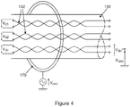
- FIG. 4 shows a schematic depiction of an apparatus according to the present invention.
- the copper cables 130 will comprise multiple pairs of twisted copper wires 132, typically from 10-100 pairs, with one pair being reserved for each customer.
- a respective signal is transmitted over each of the pairs using a differential signal.
- an apparatus 170 such as a current clamp, can be connected around all of the pairs in the cable at the cabinet and a common mode voltage signal can be transmitted over all of the copper pairs. This common mode signal can be modulated to identify the cabinet and the CAL parameter value associated with that cabinet.
- the VDSL amplifier can be adapted to detect this injected common mode voltage signal from the copper pair to which it is connected.
- Figure 5 shows a schematic depiction of an example pick up circuit in which the value C p of the capacitors is chosen such that any DC signals present on the copper pair are blocked and the value L p of the inductors are selected such that the circuit is not loaded in the chosen frequency band.
- the CAL value can be decoded from the common mode voltage signal and can be used in the operation of the VDSL amplifier. If transmitted, an identifier for the cabinet may also be stored by the VDSL amplifier and used to configure the amplifier.
- each cabinet could be assigned a unique identifier, which could be transmitted along with the CAL value. If network engineers were to be provided with a tool which could receive the common mode signal then this information could be used when performing repair and maintenance tasks. Such a tool could be of use in circumstances where a single distribution point is fed by cables which are connected to different cabinets. Furthermore, or alternatively, as the common mode injecting apparatus 170 is coupled to a single cable then it would be possible to transmit a unique cable identifier along with the cabinet identifier and/or he CAL value.
- the common mode signal is transmitted at a frequency that will propagate well to enable the detection of the signal.
- the signal would be transmitted at a frequency of at least 10kHz to minimise the inductance needed in the pick-up circuit.
- Conventional cable location equipment which is also based on a signal coupled into the cable, uses a 22kHz signal but this will be moved to 33kHz to reduce radio frequency interference so the common mode signal could use a frequency in excess of 30kHz.
- the CAL value could be transmitted periodically, for example once a second. As small amounts of data, for example 10 bytes, would be required then the data rate of 80bps would not be problematic. If more data were to be sent then spread spectrum techniques could be used to ensure that the common mode signal did not interfere with the voice or VDSL signals. Alternatively, the CAL value might be transmitted until the cabinet can detect that it has been received by the amplifier and used to configure the amplifier. This could be inferred by the OSS detecting that the signals received at the customer premises are such that the amplifier is working correctly, that is the signals are of an appropriate magnitude. Alternatively, if the OSS can determine that the customer premises equipment is operating at an appropriate data rate then it can also be inferred that the amplifier is working correctly.
- the present invention provides a method of configuring a network element, for example an amplifier in a VDSL network. Configuration is transmitted to the amplifier using a common mode voltage signal so that there is no interference with the telephony or DSL signals.
Landscapes
- Engineering & Computer Science (AREA)
- Signal Processing (AREA)
- Computer Networks & Wireless Communication (AREA)
- Power Engineering (AREA)
- Physics & Mathematics (AREA)
- Electromagnetism (AREA)
- Cable Transmission Systems, Equalization Of Radio And Reduction Of Echo (AREA)
- Amplifiers (AREA)
Description
- The present invention relates to a communications network and in particular to a communications network using digital subscriber line (DSL) technology.
- Asymmetric digital subscriber line (ADSL) systems enable data to be transmitted over a pair of metallic twisted pair (usually copper) wires to customer premises. It is thought that the maximum transmission performance that is likely to be obtained with modern variants of ADSL is a download data rate of 24 Mbps and an upload speed of about 3 Mbps. Such data rates are dependent on the length, insulation dielectric and gauge of the metallic twisted pair from the customer premises to the telephone exchange and thus many customers will receive services at significantly lower data rates.
- To improve data rates optical fibre has been installed into the access network. The greatest data rates are likely to be provided using fibre to the premises (FTTP) networks, such as passive optical networks (PONs), but there is a significant cost involved in providing fibre all the way to customer premises. Fibre to the cabinet (FTTCab) networks are known to provide an attractive solution to providing customers with high data rate services without requiring as much investment as FTTP networks. Typically in FTTCab networks, very high bit-rate digital subscriber line (VDSL) systems are used to provide data rates of 40 Mbps and higher, for both upload and download on the metallic twisted pair cables. It is believed that improvements to VDSL systems, particularly vectoring may provide data rates in excess of 100 Mbps in the future.
- DSL systems work by utilising the frequencies above those which are used by the conventional telephony signals. In particular, VDSL2 defines multiple frequency windows for downstream and upstream data, according to which internationally standardised band plan is set. Each of these windows comprises a number of data transmission carriers which normally have a 4.3125 kHz frequency separation. Each of these carriers will transmit one or more symbols with each of these symbols being used to transmit up to 15 bits of data. During a training process the insertion loss and noise level are determined for each of the carriers such that the signal to noise ratio (SNR) for each carrier can be determined. The training process determines the capacity of the upstream and downstream links in accordance with the SNRs of each of the carriers.
-
Figure 1 shows a schematic depiction of a FTTCab network in which atelephone exchange 100 is connected to a plurality ofcabinets 120 byoptical fibre cables 110. Thesecabinets 120 comprise the opto-electronic equipment necessary to send data to thecustomer premises 200 over a twisted metallic (usually copper)cable 130. Typically, a customer will use the communications network to access the internet and to access data such as video on demand services. Alternatively, the network may be used to transmit television channels which might conventionally be transmitted using a terrestrial or satellite transmission channel. One of the limitations of DSL systems is that the data signals are attenuated as they are transmitted across the metallic twisted pair cables. The maximum design range of the VDSL technology from the cabinet to the customer premises is typically 1.5-2km, but often some outlying customer premises are located at distances much greater than the maximum design range. Beyond this maximum range then it is not usually possible to deliver a reliable data service of greater than 2Mbps (this has been set by Ofcom as being the minimum data rate for all UK customers by the end of 2015). However, there are a significant number of customers whose properties are significantly further from the cabinet than this maximum range. A solution to this problem would be to deploy fibre further into the periphery of the access network but this is an expensive solution for a small number of customer premises. - Another solution is to use a VDSL amplifier to boost the signals in one or more of the frequency bands assigned to downloading (and to also uploading). Such amplifiers can increase the maximum range of a VDSL system to typically 3-4km. An example of such an amplifier is the VBA (VDSL Broadband Amplifier) provided by Actelis Networks.
Figure 2 shows a schematic depiction of the network described above with reference toFigure 1 in which aVDSL amplifier 150 has been placed in line with each of the metallic twisted pair cables that form the D-side or DistributionSide access network 130. - When a
VDSL cabinet 120 is installed, it is necessary to determine a parameter referred to as the CAL, or Cabinet Assigned Loss. This parameter describes the electrical length of the cables between the exchange and the cabinet (this portion of the access network is referred to as the Exchange-side (or E-side) network). The CAL value will be entered into the DSLAM housed in the cabinet and this value will be used for determining the power spectral density (PSD) of the VDSL signals used when transmitting data to the customer premises. Furthermore, it is necessary that the CAL parameter value be entered into a VDSL amplifier to ensure its proper operation within the limits of any defined spectrum management rules such as the UK ANFP (NICC ND:1602). In the UK ANFP, the CAL parameter is a whole number value in the range 0-52dB, and each VDSL2 cabinet or DSLAM has such a value set which is a function of the E-side length and cable routing from the serving exchange to the cabinet. -
GB 2 503 636 WO2010/111456 discloses a system which uses RDID tags to monitor patch cord connections to detect insertions or removals of patch cords and to map networks.EP2509250 discloses apparatus for creating DSL phantom mode signals over multiple DSL lines. - According to a first aspect of the present invention there is provided a method of a) modulating a common mode voltage signal onto an electrical conductor at a first location, the common mode voltage signal carrying data comprising one or more operational parameters; b) detecting the common mode voltage signal from the electrical conductor at a second location; the method being characterised in that the one or more operational parameters determine the gain of an amplifier and the method comprises the further step of: c) operating an amplifier located at the second location in accordance with the one or more operational parameters.
- The data carried using the common mode voltage signal may further comprises data identifying one or more network elements: these network elements may be a cabinet or a cable in a FTTCab network. The common mode voltage signal may be transmitted at a frequency in excess of 10 kHz., or preferably at a frequency in excess of 30 kHz.
- The common mode voltage signal may be transmitted until it can be determined that the amplifier is being operated in accordance with the one or more operational parameters. The operation of the amplifier may be determined in accordance with the data signals that are received at a customer premises which is connected to the communications network.. The data for the one or more operational parameters may determine the gain of an amplifier. The common mode voltage signal may further comprise data identifying one or more network elements. The common mode voltage signal may further comprise data identifying a cabinet in a FTTCab network or a cable.
- According to a second aspect of the present invention there is provided a communications network, the network comprising a fibre optic cable connection to a cabinet, a metallic cable connecting the cabinet to a customer premises and an amplifier connected to the metallic cable at a location intermediate the cabinet and the customer premises; the network being configured, in use, to: modulate a common mode voltage signal onto the metallic cable at the cabinet, detect the common mode voltage signal from the metallic cable at the amplifier; characterised in that the common mode voltage signal carries data comprising one or more operational parameters which determine the gain of an amplifier and the amplifier is operated in accordance with the one or more operational parameters.
- According to a third aspect of the present invention there is provided an amplifier for use in a communications network, wherein the amplifier is connected to a cabinet via a metallic cable and, in use, the amplifier is configured to: detect a common mode voltage signal from the metallic cable, the common mode voltage signal having been modulated onto the metallic cable at the cabinet, characterised in that the common mode voltage signal carries data comprising one or more operational parameters which determine the gain of the amplifier and the amplifier is operated in accordance with the one or more operational parameters.
- Embodiments of the present invention will now be described, by way of example only, with reference to the accompanying drawings in which:
-
Figure 1 shows a schematic depiction of a FTTCab network in which a telephone exchange is connected to a plurality of cabinets by optical fibre cables; -
Figure 2 shows a schematic depiction of a FTTCab network further comprising VDSL amplifiers connected in line with the copper cables; -
Figure 3 shows a schematic depiction of a VDSL amplifier; -
Figure 4 shows a schematic depiction of an apparatus according to the present invention; and -
Figure 5 shows a schematic depiction of an example pick up circuit for use in a VDSL amplifier. -
Figure 3 shows a schematic depiction of aVDSL amplifier 150 which comprisespower convertor 1510, first 2/4line hybrid 1520, firstband pass filter 1530,downstream amplifier 1540, secondband pass filter 1550, second 2/4line hybrid 1560 and thirdband pass filter 1570. The first and second 2/4 line hybrids act to allow the telephony signals to pass through unaltered. The firstband pass filter 1530 separates one or more of the downstream frequency bands such that the frequency band(s) can be amplified by thedownstream amplifier 1540. The secondband pass filter 1550 act so as to ensure that the amplification does not introduce any noise or interference outside of the specified downstream frequency bands. For example, plan 998ADE17 specifies three downstream frequency bands: 0.138-3.75 MHz, 5.2-8.5 MHz and 12-17.664 MHz. The amplified signal is then reintroduced onto the metallic twisted pair cable so that it can be transmitted to thecustomer premises 200. -
Figure 4 shows a schematic depiction of an apparatus according to the present invention. Thecopper cables 130 will comprise multiple pairs oftwisted copper wires 132, typically from 10-100 pairs, with one pair being reserved for each customer. As can be seen fromFigure 4 , a respective signal is transmitted over each of the pairs using a differential signal. Furthermore, anapparatus 170, such as a current clamp, can be connected around all of the pairs in the cable at the cabinet and a common mode voltage signal can be transmitted over all of the copper pairs. This common mode signal can be modulated to identify the cabinet and the CAL parameter value associated with that cabinet. - The VDSL amplifier can be adapted to detect this injected common mode voltage signal from the copper pair to which it is connected.
Figure 5 shows a schematic depiction of an example pick up circuit in which the value Cp of the capacitors is chosen such that any DC signals present on the copper pair are blocked and the value Lp of the inductors are selected such that the circuit is not loaded in the chosen frequency band. Once received, the CAL value can be decoded from the common mode voltage signal and can be used in the operation of the VDSL amplifier. If transmitted, an identifier for the cabinet may also be stored by the VDSL amplifier and used to configure the amplifier. - It will be understood that further information may be transmitted in addition to the CAL value. For example, each cabinet could be assigned a unique identifier, which could be transmitted along with the CAL value. If network engineers were to be provided with a tool which could receive the common mode signal then this information could be used when performing repair and maintenance tasks. Such a tool could be of use in circumstances where a single distribution point is fed by cables which are connected to different cabinets. Furthermore, or alternatively, as the common
mode injecting apparatus 170 is coupled to a single cable then it would be possible to transmit a unique cable identifier along with the cabinet identifier and/or he CAL value. - It should be understood that the amount of data to be transmitted using the common mode signal is very small. Under normal circumstances putting too much power into the common mode is avoided so it will be necessary to send the common mode signal at a very low power level. Given this requirement it is preferred if the common mode signal is transmitted at a frequency that will propagate well to enable the detection of the signal. Preferably the signal would be transmitted at a frequency of at least 10kHz to minimise the inductance needed in the pick-up circuit. Conventional cable location equipment, which is also based on a signal coupled into the cable, uses a 22kHz signal but this will be moved to 33kHz to reduce radio frequency interference so the common mode signal could use a frequency in excess of 30kHz.
- The CAL value could be transmitted periodically, for example once a second. As small amounts of data, for example 10 bytes, would be required then the data rate of 80bps would not be problematic. If more data were to be sent then spread spectrum techniques could be used to ensure that the common mode signal did not interfere with the voice or VDSL signals. Alternatively, the CAL value might be transmitted until the cabinet can detect that it has been received by the amplifier and used to configure the amplifier. This could be inferred by the OSS detecting that the signals received at the customer premises are such that the amplifier is working correctly, that is the signals are of an appropriate magnitude. Alternatively, if the OSS can determine that the customer premises equipment is operating at an appropriate data rate then it can also be inferred that the amplifier is working correctly.
- The present invention provides a method of configuring a network element, for example an amplifier in a VDSL network. Configuration is transmitted to the amplifier using a common mode voltage signal so that there is no interference with the telephony or DSL signals.
Claims (12)
- A method of operating a communications network (100), the method comprising the steps of:a) modulating a common mode voltage signal onto an electrical conductor (130) at a first location, the common mode voltage signal carrying data comprising one or more operational parameters;b) detecting the common mode voltage signal from the electrical conductor at a second location;the method being characterised in that the one or more operational parameters determine the gain of an amplifier and the method comprises the further step of:
c) operating an amplifier (150) located at the second location in accordance with the one or more operational parameters. - A method according to claim 1, wherein the data carried using the common mode voltage signal further comprises data identifying one or more network elements.
- A method according to claim 2, wherein the common mode voltage signal further comprises data identifying a cabinet (120) in a FTTCab network or a cable (130) in the FTTCab network.
- A method according to any of Claims 1 to 3, in which the common mode voltage signal is transmitted at a frequency in excess of 10 kHz.
- A method according to any of Claims 1 to 4, in which the common mode voltage signal is transmitted at a frequency in excess of 30 kHz.
- A method according to any of Claims 1 to 5, wherein the one or more operational parameters are transmitted periodically.
- A method according to any of Claims 1 to 6, wherein the common mode voltage signal is transmitted until it can be determined that the amplifier (150) is being operated in accordance with the one or more operational parameters.
- A method according to Claim 7, wherein the operation of the amplifier (150) can be determined in accordance with the data signals that are received at a customer premises (200) which is connected to the communications network (100).
- A communications network (100), the network comprising a fibre optic cable connection (110) to a cabinet (120), a metallic cable (130) connecting the cabinet to a customer premises (200) and an amplifier (150) connected to the metallic cable at a location intermediate the cabinet and the customer premises; the network being configured, in use, to:modulate a common mode voltage signal onto the metallic cable (130) at the cabinet,detect the common mode voltage signal from the metallic cable at the amplifier;characterised in that the common mode voltage signal carries data comprising one or more operational parameters which determine the gain of the amplifier and the amplifier is operated in accordance with the one or more operational parameters.
- A communications network according to Claim 9, wherein the amplifier comprises a VDSL amplifier.
- An amplifier (150) for use in a communications network (100), wherein the amplifier is connected to a cabinet (120) via a metallic cable (130) and, in use, the amplifier is configured to:detect a common mode voltage signal from the metallic cable (130), the common mode voltage signal having been modulated onto the metallic cable at the cabinet,characterised in that the common mode voltage signal carries data comprising one or more operational parameters which determine the gain of the amplifier and the amplifier is operated in accordance with the one or more operational parameters.
- An amplifier according to Claim 11, wherein the amplifier comprises a VDSL amplifier.
Applications Claiming Priority (2)
| Application Number | Priority Date | Filing Date | Title |
|---|---|---|---|
| EP14250064 | 2014-03-31 | ||
| PCT/GB2015/050944 WO2015150755A1 (en) | 2014-03-31 | 2015-03-27 | Communications network |
Publications (2)
| Publication Number | Publication Date |
|---|---|
| EP3127313A1 EP3127313A1 (en) | 2017-02-08 |
| EP3127313B1 true EP3127313B1 (en) | 2020-02-12 |
Family
ID=50478796
Family Applications (1)
| Application Number | Title | Priority Date | Filing Date |
|---|---|---|---|
| EP15714266.2A Active EP3127313B1 (en) | 2014-03-31 | 2015-03-27 | Communications network |
Country Status (5)
| Country | Link |
|---|---|
| US (1) | US10404494B2 (en) |
| EP (1) | EP3127313B1 (en) |
| CN (1) | CN106416212B (en) |
| GB (1) | GB2525458A (en) |
| WO (1) | WO2015150755A1 (en) |
Families Citing this family (1)
| Publication number | Priority date | Publication date | Assignee | Title |
|---|---|---|---|---|
| GB2525458A (en) * | 2014-03-31 | 2015-10-28 | British Telecomm | Communications network |
Family Cites Families (11)
| Publication number | Priority date | Publication date | Assignee | Title |
|---|---|---|---|---|
| GB9522737D0 (en) * | 1995-11-07 | 1996-01-10 | West End System Corp | Noise cancellation in twisted pairs |
| DE102004039022B4 (en) * | 2004-08-11 | 2007-09-27 | Infineon Technologies Ag | xDSL multistandard driver circuit |
| US7656956B2 (en) * | 2005-01-14 | 2010-02-02 | Motorola, Inc. | Data, power and supervisory signaling over twisted pairs |
| CA2616409C (en) * | 2005-08-08 | 2015-06-16 | Tino Zottola | Shared dsl network and deployment method |
| US9113236B2 (en) * | 2009-03-25 | 2015-08-18 | Panduit Corp. | Physical layer management using RFID modules and common mode signaling |
| GB2503636B (en) * | 2009-03-27 | 2014-05-07 | Cable Sense Ltd | Apparatuses and methods for coupling a signal to and/or from a cable |
| US8232834B2 (en) * | 2009-05-07 | 2012-07-31 | Analog Devices, Inc. | Boosting xDSL amplifier supply power on-demand |
| US8391321B2 (en) * | 2010-06-10 | 2013-03-05 | Broadcom Corporation | Method and system for patch panel port identification and verification |
| EP2509250B1 (en) * | 2011-04-08 | 2013-12-11 | Alcatel Lucent | Combination device for DSL phantom mode signals in a telecommunication system |
| US8504418B1 (en) * | 2012-07-19 | 2013-08-06 | Benjamin P. Dimock | Incenting answer quality |
| GB2525458A (en) * | 2014-03-31 | 2015-10-28 | British Telecomm | Communications network |
-
2014
- 2014-10-17 GB GB1418458.4A patent/GB2525458A/en not_active Withdrawn
-
2015
- 2015-03-27 US US15/300,986 patent/US10404494B2/en active Active
- 2015-03-27 CN CN201580027316.2A patent/CN106416212B/en active Active
- 2015-03-27 EP EP15714266.2A patent/EP3127313B1/en active Active
- 2015-03-27 WO PCT/GB2015/050944 patent/WO2015150755A1/en not_active Ceased
Non-Patent Citations (1)
| Title |
|---|
| None * |
Also Published As
| Publication number | Publication date |
|---|---|
| CN106416212A (en) | 2017-02-15 |
| US10404494B2 (en) | 2019-09-03 |
| GB201418458D0 (en) | 2014-12-03 |
| WO2015150755A1 (en) | 2015-10-08 |
| CN106416212B (en) | 2019-04-26 |
| EP3127313A1 (en) | 2017-02-08 |
| US20170026200A1 (en) | 2017-01-26 |
| GB2525458A (en) | 2015-10-28 |
Similar Documents
| Publication | Publication Date | Title |
|---|---|---|
| US7321291B2 (en) | Power line communications system and method of operating the same | |
| US10264136B2 (en) | Resource allocation in a digital communication network | |
| US20090268795A1 (en) | Method, arrangement and device for transmitting information between a central unit and at least one decentralized unit in a communication network | |
| EP1337062A2 (en) | Method and system for link adaption in high-speed communications depending on link quality, thus reducing cross-talk and avoiding bridged taps | |
| US10404494B2 (en) | Communications networks | |
| US20050245134A1 (en) | Method and apparatus for improved data and video delivery | |
| EP2965497B1 (en) | Method and apparatus in a communications network | |
| US9813106B2 (en) | Signal conditioner for bi-directional radio frequency signals in a telecommunications network | |
| TWI603595B (en) | High Speed Copper Coexistence System and Automatic Setting Method | |
| KR102212309B1 (en) | Method for detecting a noise induced by a powerline system on a twisted pair cable | |
| GB2542807A (en) | Communications network | |
| Begović et al. | A simple analysis of copper local loop faults in FTTB environment | |
| EP3777004B1 (en) | Hybrid optical fibre metallic access network | |
| GB2571074A (en) | Network | |
| EP3471340B1 (en) | Transmission mode configuration apparatus, and transmission mode configuration method using same in copper wire-based network | |
| Cioffi et al. | Vectored DSLs and the Copper PON (CuPON) |
Legal Events
| Date | Code | Title | Description |
|---|---|---|---|
| STAA | Information on the status of an ep patent application or granted ep patent |
Free format text: STATUS: THE INTERNATIONAL PUBLICATION HAS BEEN MADE |
|
| PUAI | Public reference made under article 153(3) epc to a published international application that has entered the european phase |
Free format text: ORIGINAL CODE: 0009012 |
|
| STAA | Information on the status of an ep patent application or granted ep patent |
Free format text: STATUS: REQUEST FOR EXAMINATION WAS MADE |
|
| 17P | Request for examination filed |
Effective date: 20160929 |
|
| AK | Designated contracting states |
Kind code of ref document: A1 Designated state(s): AL AT BE BG CH CY CZ DE DK EE ES FI FR GB GR HR HU IE IS IT LI LT LU LV MC MK MT NL NO PL PT RO RS SE SI SK SM TR |
|
| AX | Request for extension of the european patent |
Extension state: BA ME |
|
| DAV | Request for validation of the european patent (deleted) | ||
| DAX | Request for extension of the european patent (deleted) | ||
| RAP1 | Party data changed (applicant data changed or rights of an application transferred) |
Owner name: BRITISH TELECOMMUNICATIONS PUBLIC LIMITED COMPANY |
|
| GRAP | Despatch of communication of intention to grant a patent |
Free format text: ORIGINAL CODE: EPIDOSNIGR1 |
|
| STAA | Information on the status of an ep patent application or granted ep patent |
Free format text: STATUS: GRANT OF PATENT IS INTENDED |
|
| INTG | Intention to grant announced |
Effective date: 20190905 |
|
| GRAS | Grant fee paid |
Free format text: ORIGINAL CODE: EPIDOSNIGR3 |
|
| GRAA | (expected) grant |
Free format text: ORIGINAL CODE: 0009210 |
|
| STAA | Information on the status of an ep patent application or granted ep patent |
Free format text: STATUS: THE PATENT HAS BEEN GRANTED |
|
| AK | Designated contracting states |
Kind code of ref document: B1 Designated state(s): AL AT BE BG CH CY CZ DE DK EE ES FI FR GB GR HR HU IE IS IT LI LT LU LV MC MK MT NL NO PL PT RO RS SE SI SK SM TR |
|
| REG | Reference to a national code |
Ref country code: GB Ref legal event code: FG4D |
|
| REG | Reference to a national code |
Ref country code: CH Ref legal event code: EP |
|
| REG | Reference to a national code |
Ref country code: AT Ref legal event code: REF Ref document number: 1233658 Country of ref document: AT Kind code of ref document: T Effective date: 20200215 |
|
| REG | Reference to a national code |
Ref country code: DE Ref legal event code: R096 Ref document number: 602015046738 Country of ref document: DE |
|
| REG | Reference to a national code |
Ref country code: IE Ref legal event code: FG4D |
|
| PG25 | Lapsed in a contracting state [announced via postgrant information from national office to epo] |
Ref country code: FI Free format text: LAPSE BECAUSE OF FAILURE TO SUBMIT A TRANSLATION OF THE DESCRIPTION OR TO PAY THE FEE WITHIN THE PRESCRIBED TIME-LIMIT Effective date: 20200212 Ref country code: NO Free format text: LAPSE BECAUSE OF FAILURE TO SUBMIT A TRANSLATION OF THE DESCRIPTION OR TO PAY THE FEE WITHIN THE PRESCRIBED TIME-LIMIT Effective date: 20200512 Ref country code: RS Free format text: LAPSE BECAUSE OF FAILURE TO SUBMIT A TRANSLATION OF THE DESCRIPTION OR TO PAY THE FEE WITHIN THE PRESCRIBED TIME-LIMIT Effective date: 20200212 |
|
| REG | Reference to a national code |
Ref country code: LT Ref legal event code: MG4D |
|
| REG | Reference to a national code |
Ref country code: NL Ref legal event code: MP Effective date: 20200212 |
|
| PG25 | Lapsed in a contracting state [announced via postgrant information from national office to epo] |
Ref country code: GR Free format text: LAPSE BECAUSE OF FAILURE TO SUBMIT A TRANSLATION OF THE DESCRIPTION OR TO PAY THE FEE WITHIN THE PRESCRIBED TIME-LIMIT Effective date: 20200513 Ref country code: BG Free format text: LAPSE BECAUSE OF FAILURE TO SUBMIT A TRANSLATION OF THE DESCRIPTION OR TO PAY THE FEE WITHIN THE PRESCRIBED TIME-LIMIT Effective date: 20200512 Ref country code: HR Free format text: LAPSE BECAUSE OF FAILURE TO SUBMIT A TRANSLATION OF THE DESCRIPTION OR TO PAY THE FEE WITHIN THE PRESCRIBED TIME-LIMIT Effective date: 20200212 Ref country code: IS Free format text: LAPSE BECAUSE OF FAILURE TO SUBMIT A TRANSLATION OF THE DESCRIPTION OR TO PAY THE FEE WITHIN THE PRESCRIBED TIME-LIMIT Effective date: 20200612 Ref country code: SE Free format text: LAPSE BECAUSE OF FAILURE TO SUBMIT A TRANSLATION OF THE DESCRIPTION OR TO PAY THE FEE WITHIN THE PRESCRIBED TIME-LIMIT Effective date: 20200212 Ref country code: LV Free format text: LAPSE BECAUSE OF FAILURE TO SUBMIT A TRANSLATION OF THE DESCRIPTION OR TO PAY THE FEE WITHIN THE PRESCRIBED TIME-LIMIT Effective date: 20200212 |
|
| PG25 | Lapsed in a contracting state [announced via postgrant information from national office to epo] |
Ref country code: NL Free format text: LAPSE BECAUSE OF FAILURE TO SUBMIT A TRANSLATION OF THE DESCRIPTION OR TO PAY THE FEE WITHIN THE PRESCRIBED TIME-LIMIT Effective date: 20200212 |
|
| PG25 | Lapsed in a contracting state [announced via postgrant information from national office to epo] |
Ref country code: CZ Free format text: LAPSE BECAUSE OF FAILURE TO SUBMIT A TRANSLATION OF THE DESCRIPTION OR TO PAY THE FEE WITHIN THE PRESCRIBED TIME-LIMIT Effective date: 20200212 Ref country code: ES Free format text: LAPSE BECAUSE OF FAILURE TO SUBMIT A TRANSLATION OF THE DESCRIPTION OR TO PAY THE FEE WITHIN THE PRESCRIBED TIME-LIMIT Effective date: 20200212 Ref country code: RO Free format text: LAPSE BECAUSE OF FAILURE TO SUBMIT A TRANSLATION OF THE DESCRIPTION OR TO PAY THE FEE WITHIN THE PRESCRIBED TIME-LIMIT Effective date: 20200212 Ref country code: DK Free format text: LAPSE BECAUSE OF FAILURE TO SUBMIT A TRANSLATION OF THE DESCRIPTION OR TO PAY THE FEE WITHIN THE PRESCRIBED TIME-LIMIT Effective date: 20200212 Ref country code: EE Free format text: LAPSE BECAUSE OF FAILURE TO SUBMIT A TRANSLATION OF THE DESCRIPTION OR TO PAY THE FEE WITHIN THE PRESCRIBED TIME-LIMIT Effective date: 20200212 Ref country code: SM Free format text: LAPSE BECAUSE OF FAILURE TO SUBMIT A TRANSLATION OF THE DESCRIPTION OR TO PAY THE FEE WITHIN THE PRESCRIBED TIME-LIMIT Effective date: 20200212 Ref country code: LT Free format text: LAPSE BECAUSE OF FAILURE TO SUBMIT A TRANSLATION OF THE DESCRIPTION OR TO PAY THE FEE WITHIN THE PRESCRIBED TIME-LIMIT Effective date: 20200212 Ref country code: PT Free format text: LAPSE BECAUSE OF FAILURE TO SUBMIT A TRANSLATION OF THE DESCRIPTION OR TO PAY THE FEE WITHIN THE PRESCRIBED TIME-LIMIT Effective date: 20200705 Ref country code: SK Free format text: LAPSE BECAUSE OF FAILURE TO SUBMIT A TRANSLATION OF THE DESCRIPTION OR TO PAY THE FEE WITHIN THE PRESCRIBED TIME-LIMIT Effective date: 20200212 |
|
| REG | Reference to a national code |
Ref country code: CH Ref legal event code: PL |
|
| REG | Reference to a national code |
Ref country code: DE Ref legal event code: R097 Ref document number: 602015046738 Country of ref document: DE |
|
| REG | Reference to a national code |
Ref country code: AT Ref legal event code: MK05 Ref document number: 1233658 Country of ref document: AT Kind code of ref document: T Effective date: 20200212 |
|
| PG25 | Lapsed in a contracting state [announced via postgrant information from national office to epo] |
Ref country code: MC Free format text: LAPSE BECAUSE OF FAILURE TO SUBMIT A TRANSLATION OF THE DESCRIPTION OR TO PAY THE FEE WITHIN THE PRESCRIBED TIME-LIMIT Effective date: 20200212 |
|
| PLBE | No opposition filed within time limit |
Free format text: ORIGINAL CODE: 0009261 |
|
| STAA | Information on the status of an ep patent application or granted ep patent |
Free format text: STATUS: NO OPPOSITION FILED WITHIN TIME LIMIT |
|
| REG | Reference to a national code |
Ref country code: BE Ref legal event code: MM Effective date: 20200331 |
|
| PG25 | Lapsed in a contracting state [announced via postgrant information from national office to epo] |
Ref country code: LU Free format text: LAPSE BECAUSE OF NON-PAYMENT OF DUE FEES Effective date: 20200327 |
|
| 26N | No opposition filed |
Effective date: 20201113 |
|
| PG25 | Lapsed in a contracting state [announced via postgrant information from national office to epo] |
Ref country code: IT Free format text: LAPSE BECAUSE OF FAILURE TO SUBMIT A TRANSLATION OF THE DESCRIPTION OR TO PAY THE FEE WITHIN THE PRESCRIBED TIME-LIMIT Effective date: 20200212 Ref country code: AT Free format text: LAPSE BECAUSE OF FAILURE TO SUBMIT A TRANSLATION OF THE DESCRIPTION OR TO PAY THE FEE WITHIN THE PRESCRIBED TIME-LIMIT Effective date: 20200212 Ref country code: CH Free format text: LAPSE BECAUSE OF NON-PAYMENT OF DUE FEES Effective date: 20200331 Ref country code: LI Free format text: LAPSE BECAUSE OF NON-PAYMENT OF DUE FEES Effective date: 20200331 Ref country code: IE Free format text: LAPSE BECAUSE OF NON-PAYMENT OF DUE FEES Effective date: 20200327 |
|
| PG25 | Lapsed in a contracting state [announced via postgrant information from national office to epo] |
Ref country code: BE Free format text: LAPSE BECAUSE OF NON-PAYMENT OF DUE FEES Effective date: 20200331 Ref country code: PL Free format text: LAPSE BECAUSE OF FAILURE TO SUBMIT A TRANSLATION OF THE DESCRIPTION OR TO PAY THE FEE WITHIN THE PRESCRIBED TIME-LIMIT Effective date: 20200212 Ref country code: SI Free format text: LAPSE BECAUSE OF FAILURE TO SUBMIT A TRANSLATION OF THE DESCRIPTION OR TO PAY THE FEE WITHIN THE PRESCRIBED TIME-LIMIT Effective date: 20200212 |
|
| PG25 | Lapsed in a contracting state [announced via postgrant information from national office to epo] |
Ref country code: TR Free format text: LAPSE BECAUSE OF FAILURE TO SUBMIT A TRANSLATION OF THE DESCRIPTION OR TO PAY THE FEE WITHIN THE PRESCRIBED TIME-LIMIT Effective date: 20200212 Ref country code: MT Free format text: LAPSE BECAUSE OF FAILURE TO SUBMIT A TRANSLATION OF THE DESCRIPTION OR TO PAY THE FEE WITHIN THE PRESCRIBED TIME-LIMIT Effective date: 20200212 Ref country code: CY Free format text: LAPSE BECAUSE OF FAILURE TO SUBMIT A TRANSLATION OF THE DESCRIPTION OR TO PAY THE FEE WITHIN THE PRESCRIBED TIME-LIMIT Effective date: 20200212 |
|
| PG25 | Lapsed in a contracting state [announced via postgrant information from national office to epo] |
Ref country code: MK Free format text: LAPSE BECAUSE OF FAILURE TO SUBMIT A TRANSLATION OF THE DESCRIPTION OR TO PAY THE FEE WITHIN THE PRESCRIBED TIME-LIMIT Effective date: 20200212 Ref country code: AL Free format text: LAPSE BECAUSE OF FAILURE TO SUBMIT A TRANSLATION OF THE DESCRIPTION OR TO PAY THE FEE WITHIN THE PRESCRIBED TIME-LIMIT Effective date: 20200212 |
|
| P01 | Opt-out of the competence of the unified patent court (upc) registered |
Effective date: 20230623 |
|
| PGFP | Annual fee paid to national office [announced via postgrant information from national office to epo] |
Ref country code: GB Payment date: 20260220 Year of fee payment: 12 |
|
| PGFP | Annual fee paid to national office [announced via postgrant information from national office to epo] |
Ref country code: DE Payment date: 20260219 Year of fee payment: 12 |
|
| PGFP | Annual fee paid to national office [announced via postgrant information from national office to epo] |
Ref country code: FR Payment date: 20260219 Year of fee payment: 12 |