EP3126964B1 - User interface control and communication - Google Patents
User interface control and communication Download PDFInfo
- Publication number
- EP3126964B1 EP3126964B1 EP15716337.9A EP15716337A EP3126964B1 EP 3126964 B1 EP3126964 B1 EP 3126964B1 EP 15716337 A EP15716337 A EP 15716337A EP 3126964 B1 EP3126964 B1 EP 3126964B1
- Authority
- EP
- European Patent Office
- Prior art keywords
- user interface
- interface control
- role
- instance
- computer
- Prior art date
- Legal status (The legal status is an assumption and is not a legal conclusion. Google has not performed a legal analysis and makes no representation as to the accuracy of the status listed.)
- Active
Links
Images




Classifications
-
- G—PHYSICS
- G06—COMPUTING OR CALCULATING; COUNTING
- G06F—ELECTRIC DIGITAL DATA PROCESSING
- G06F8/00—Arrangements for software engineering
- G06F8/30—Creation or generation of source code
- G06F8/38—Creation or generation of source code for implementing user interfaces
-
- G—PHYSICS
- G06—COMPUTING OR CALCULATING; COUNTING
- G06F—ELECTRIC DIGITAL DATA PROCESSING
- G06F8/00—Arrangements for software engineering
- G06F8/30—Creation or generation of source code
- G06F8/34—Graphical or visual programming
-
- G—PHYSICS
- G06—COMPUTING OR CALCULATING; COUNTING
- G06F—ELECTRIC DIGITAL DATA PROCESSING
- G06F8/00—Arrangements for software engineering
- G06F8/30—Creation or generation of source code
- G06F8/35—Creation or generation of source code model driven
-
- G—PHYSICS
- G06—COMPUTING OR CALCULATING; COUNTING
- G06F—ELECTRIC DIGITAL DATA PROCESSING
- G06F9/00—Arrangements for program control, e.g. control units
- G06F9/06—Arrangements for program control, e.g. control units using stored programs, i.e. using an internal store of processing equipment to receive or retain programs
- G06F9/44—Arrangements for executing specific programs
- G06F9/451—Execution arrangements for user interfaces
-
- G—PHYSICS
- G06—COMPUTING OR CALCULATING; COUNTING
- G06F—ELECTRIC DIGITAL DATA PROCESSING
- G06F9/00—Arrangements for program control, e.g. control units
- G06F9/06—Arrangements for program control, e.g. control units using stored programs, i.e. using an internal store of processing equipment to receive or retain programs
- G06F9/46—Multiprogramming arrangements
- G06F9/54—Interprogram communication
-
- H—ELECTRICITY
- H04—ELECTRIC COMMUNICATION TECHNIQUE
- H04L—TRANSMISSION OF DIGITAL INFORMATION, e.g. TELEGRAPHIC COMMUNICATION
- H04L67/00—Network arrangements or protocols for supporting network services or applications
- H04L67/01—Protocols
- H04L67/10—Protocols in which an application is distributed across nodes in the network
Definitions
- a computing system often displays user interface elements called controls that the user may interact with to cause the computing system to execute respective operations, or through which the user may visualize underlying information.
- user interface controls all operate within the same process and thus may share common shared memory.
- user interface controls may not run in the same process, or even on the same machine.
- there might be a distributed application that has multiple extensions each offered by a different provider.
- the user interface controls may be offered by the different extensions that are not within the same sphere of trust.
- US 2002/070965 A1 relates to a system and method for automatically configuring program data exchange.
- a developer of a program may specify a data source and/or data target during development of the program, e.g., via a URL. If a data source is specified, the method may operate to automatically determine a GUI element operable to display (or otherwise indicate) data received from the data source and may automatically include the GUI element in the program's graphical user interface (GUI) and automatically configure the GUI element to receive and display data from the specified data source during execution of the program.
- GUI graphical user interface
- a data viewer program which, when executed, enables an end user to specify a data source, e.g., via a URL, and view data received from the data source, wherein the end user may specify any of various types of data sources, any of various types of data may be received from the data sources, and any of various types of GUI elements may be dynamically displayed to allow the end user to view the received data.
- the user interface control may also have a general function component that performs general functions that may be common across multiple user interface controls.
- the general function component may be provided by a template.
- much of the logic components may also be provided by the template, such that the functionality of the user interface element is data-driven, perhaps only involving defining the functionality of the logic components.
- At least some embodiments described herein also may relate to a protocol for use in communicating between two user interface controls to establish a communications link. For instance, a first user interface control requests information from a Second user interface control, which then obtains the requested information (e.g., by requesting the information from a user, or by soliciting some or all of the requested information from yet another user interface control recursively performing the same communication protocol). The second user interface control then provides the requested information to the first user interface control, and then awaits the validation of the requested information.
- the first user interface control might have a collector role in which the first user interface control collects information
- the second user interface control might have a provider role in which the second user interface control provides information.
- At least some embodiments described herein relate to a user interface control that has different logic components for processing different role logic depending on a role that is played by the user interface control.
- the user interface control may also have a general function component that performs general functions that may be common across multiple user interface controls.
- the general function component may be provided by a template.
- much of the logic components may also be provided by the template, such that the functionality of the user interface element is data-driven, perhaps only involving defining the functionality of the logic components in a declarative way.
- At least some embodiments described herein also may relate to a protocol for use in communicating between two user interface controls to establish a communications link. For instance, a first user interface control requests information from a second user interface control, which then obtains the requested information (e.g., by requesting the information from a user, or by soliciting some or all of the requested information from yet another user interface control recursively performing the same communication protocol). The second user interface control then provides the requested information to the first user interface control, and then awaits the validation of the requested information.
- the first user interface control might have a collector role in which the first user interface control collects information
- the second user interface control might have a provider role in which the second user interface control provides information.
- the hierarchy can be composed with the components being loosely coupled, and reusable in multiple flow. Accordingly, any given user interface control may perform both collector and provider roles.
- Computing systems are now increasingly taking a wide variety of forms. Computing systems may, for example, be handheld devices, appliances, laptop computers, desktop computers, mainframes, distributed computing systems, or even devices that have not conventionally been considered a computing system.
- the term "computing system” is defined broadly as including any device or system (or combination thereof) that includes at least one physical and tangible processor, and a physical and tangible memory capable of having thereon computer-executable instructions that may be executed by the processor.
- the memory may take any form and may depend on the nature and form of the computing system.
- a computing system may be distributed over a network environment and may include multiple constituent computing systems.
- a computing system 100 typically includes at least one processing unit 102 and memory 104.
- the memory 104 may be physical system memory, which may be volatile, non-volatile, or some combination of the two.
- the term “memory” may also be used herein to refer to non-volatile mass storage such as physical storage media. If the computing system is distributed, the processing, memory and/or storage capability may be distributed as well.
- the term "executable module” or “executable component” can refer to software objects, routines, or methods that may be executed on the computing system. The different components, modules, engines, and services described herein may be implemented as objects or processes that execute on the computing system (e.g., as separate threads).
- embodiments are described with reference to acts that are performed by one or more computing systems. If such acts are implemented in software, one or more processors of the associated computing system that performs the act direct the operation of the computing system in response to having executed computer-executable instructions.
- such computer-executable instructions may be embodied on one or more computer-readable media that form a computer program product.
- An example of such an operation involves the manipulation of data.
- the computer-executable instructions (and the manipulated data) may be stored in the memory 104 of the computing system 100.
- Computing system 100 may also contain communication channels 108 that allow the computing system 100 to communicate with other message processors over, for example, network 110.
- the computing system 100 also includes a display 112 for displaying user interfaces such as those described herein.
- Embodiments described herein may comprise or utilize a special purpose or general-purpose computer including computer hardware, such as, for example, one or more processors and system memory, as discussed in greater detail below.
- Embodiments described herein also include physical and other computer-readable media for carrying or storing computer-executable instructions and/or data structures.
- Such computer-readable media can be any available media that can be accessed by a general purpose or special purpose computer system.
- Computer-readable media that store computer-executable instructions are physical storage media.
- Computer-readable media that carry computer-executable instructions are transmission media.
- embodiments of the invention can comprise at least two distinctly different kinds of computer-readable media: computer storage media and transmission media.
- Computer storage media includes RAM, ROM, EEPROM, CD-ROM or other optical disk storage, magnetic disk storage or other magnetic storage devices, or any other tangible medium which can be used to store desired program code means in the form of computer-executable instructions or data structures and which can be accessed by a general purpose or special purpose computer.
- a "network” is defined as one or more data links that enable the transport of electronic data between computer systems and/or modules and/or other electronic devices.
- a network or another communications connection can include a network and/or data links which can be used to carry or desired program code means in the form of computer-executable instructions or data structures and which can be accessed by a general purpose or special purpose computer. Combinations of the above should also be included within the scope of computer-readable media.
- program code means in the form of computer-executable instructions or data structures can be transferred automatically from transmission media to computer storage media (or vice versa).
- computer-executable instructions or data structures received over a network or data link can be buffered in RAM within a network interface module (e.g., a "NIC"), and then eventually transferred to computer system RAM and/or to less volatile computer storage media at a computer system.
- a network interface module e.g., a "NIC”
- NIC network interface module
- computer storage media can be included in computer system components that also (or even primarily) utilize transmission media.
- Computer-executable instructions comprise, for example, instructions and data which, when executed at a processor, cause a general purpose computer, special purpose computer, or special purpose processing device to perform a certain function or group of functions.
- the computer executable instructions may be, for example, binaries, intermediate format instructions such as assembly language, or even source code.
- the invention may be practiced in network computing environments with many types of computer system configurations, including, personal computers, desktop computers, laptop computers, message processors, hand-held devices, multi-processor systems, microprocessor-based or programmable consumer electronics, network PCs, minicomputers, mainframe computers, mobile telephones, PDAs, pagers, routers, switches, and the like.
- the invention may also be practiced in distributed system environments where local and remote computer systems, which are linked (either by hardwired data links, wireless data links, or by a combination of hardwired and wireless data links) through a network, both perform tasks.
- program modules may be located in both local and remote memory storage devices.
- Figure 2 illustrates a particular user interface control 200 that may represent a software component that may be implemented by, for instance, the computing system 100 of Figure 1 , and which may result in a corresponding user interface element to be displayed on the display 112.
- the user interface control 200 is capable of implementing any one or more of several roles.
- the particular user interface control 200 includes three different role logic components 201, 202 and 203 for processing respective first, second, and third logic when the particular user interface control 200 has respective first, second and third roles.
- the user interface control 200 has a first role logic component 201 for processing first role logic when the user interface control 200 has a first role; has a second role logic component 202 for processing second role logic when the user interface control 200 has a second role; and has a third role logic component 202 for processing third role logic when the user interface control 200 has a third role.
- the ellipses 204 represent that there may be any number of multiple roles implemented by the user interface control 200.
- the user interface control 200 also includes a general function component 210 for performing general functions.
- Such general functions may include, for example, a communication function 211 for communicating with other user interface controls to receive data from or provide data to the other user interface controls.
- General functions might also include a role management function 212 for maintain a record of a current role or roles of the user interface control 200.
- the user interface control may have been created from a template of a set of available templates. Each template may include a corresponding general function component as well as much of the code for each of the role logic components.
- the construction of the user interface control from one of the user interface templates may essentially be data driven.
- the template may encompass user interface composition aspects and have a companion code artifact. Accordingly, the template may encapsulate visuals, interaction, and back-end behavior and logic.
- Figure 3 illustrates a user interface control creation environment 300 in which a creation module 310 is fed control creation data 301, a template selection 302, and role identifier 303.
- the available templates 320 are illustrated as including three user interface control templates 321, 322 and 323, although the ellipses 324 represent that there may be any number of user interface control templates 320 made available for user interface control authors.
- the author For each role that the user interface control is to have a corresponding role logic component for, the author provides creation data 301 and a template selector 302.
- the creation module 310 then provides a user interface control 305 that has the appropriate role logic components (e.g., 201, 202, 203 and 204), and also has the correct general functions 210.
- the appropriate role logic components e.g., 201, 202, 203 and 204
- a wizard template may be used for role logic components that are to guide a user through multiple steps.
- the wizard template may come with all of the general code for performing steps of the task, and may just require the name of the step and a pointer to the next step.
- the template may be data-driven where the user provides the data about the steps (e.g., name, pointer destination, and so forth), and an optional controller logic to react to changes or completion of those steps.
- a forms template may be used for role logic components that are to display fillable fields. The user might just provide a template for the form layout, and appropriate data.
- a selector template may be used for role logic components that present a list of selections to the user, in which case, perhaps just the name of the selectable items are provided as data.
- the created user interface control may be reusable in different contexts.
- the operation of each instance of the same user interface control may differ depending on the input data and on the context in which the instance of the user interface control operates.
- multiple instances of the same user interface control may be used in different processing flows.
- the first role implemented by the first role logic component 201 may be, for example, a collector role in which the user interface control collects data from one or more other interface controls.
- the second role implemented by the second role logic component 202 may be, for example, a provider role in which the particular user interface control provides data to one or more other user interface controls.
- a third role might be a provisioning role.
- the provisioning user interface control may have gathered data for a particular purpose.
- the provisioning role means that the user interface control may then use the gathered data in order to perform some other task such as, for example, the creation of a resource.
- a communications link between two user interface controls may be implemented between first and second user interface controls when the first user interface control performs the first role of collector and the second user interface control performs the second role of provider.
- the first user interface control collects data provided by the second user interface control, after the first user interface control requests such information. More regarding an example communication protocol for the communications link will be described below.
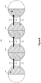
- FIG. 4 abstractly illustrates an environment 400 in which multiple user interface controls are coupled via multiple communication links.
- Each user interface control is represented by a corresponding circle.
- the environment 400 is illustrated as including four user interface controls 401 through 404. If the right half of the circle is filled with diagonal fill, this represents that the user interface control has the collector role. If the left half of the circle is filled with diagonal fill, this represents that the user interface control has the provider role. Accordingly, the user interface control 401 has the collector role, the user interface control 402 has both roles of collector and provider, the user interface control 403 has both roles of collector and provider, and the user interface control 404 has the role of provider.
- a communication link 411 is established between the user interface control 401 (due to its collector role) and the user interface 402 (due to its provider role).
- a communication link 412 is established between the user interface control 402 (due to its collector role) and the user interface 403 (due to its provider role).
- the communication link 413 is established between the user interface control 403 (due to its collector role) and the user interface 404 (due to its provider role).
- the user interface control 401 submits an information request (as represented by arrow 421) to the user interface control 402, and receives the requested information (as represented by arrow 431) from the user interface control 402.
- the user interface control 401 might also request information from a user.
- the user interface control 401 also has the provisioning role as represented by the asterisk. Accordingly, the user interface control 401 may thus use the requested information to perform some task, such as the creation of the resource.
- the user interface control 401 may also cause the user interface control 402 to be instantiated, and submit input data to the user interface control 402.
- the user interface control 402 submits an information request (as represented by arrow 422) to the user interface control 403, and receives the requested information (as represented by arrow 432) from the user interface control 403.
- the user interface control 402 may also prompt the user to input data.
- the user interface control 402 may also cause the user interface control 403 to be instantiated, and submit input data to the user interface control 403.
- the user interface control 403 submits yet another information request (as represented by arrow 423) to the user interface control 404, and receives the requested information (as represented by arrow 433) from the user interface control 404.
- the user interface control 403 may also prompt the user to input data.
- the user interface control 403 may also cause the user interface control 404 to be instantiated, and submit input data to the user interface control 404.
- the user interface control 404 may prompt a user to input data. Once that input data is provided, and the user confirms the input data, the requested information is provided back to the user interface control 403.
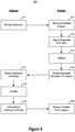
- Figure 5 illustrates a flowchart of a method 500 of a first user interface control (in its capacity as a collector) to acquire data from a second user interface control (in its capacity as a provider).
- the communication protocol does not require that the user interface controls have shared memory. Accordingly, the user interface controls may be running in different processes, or even on different machines. Thus, the principles described herein may be effectively used in distributed application and/or in applications that have multiple sources providing user interface controls (as would be the case when an application allows extension authors to author extensions to the application).
- the method 500 includes acts that are performed by the first user interface control in the communications link (as represented in the left column of Figure 5 under the heading “Collector”). The method 500 also includes acts that are performed by the second user interface control in the communications link (as represented in the left column of Figure 5 under the heading "Provider”).
- the collector first request information from a provider (act 511).
- the collector may also instantiate the user interface control that acts as provider, and cause the instantiated user interface control to take on the provider role.
- the collector may also provide input data to the provider, which input data likely is much smaller than the total amount of data available to the collector.
- the input data might also include metadata, where the input data can be used as defaults for some of the fields.
- Figure 6 illustrates a link communication diagram 600 showing three nodes of communication including the collector, the provider, and the end user.
- the collector is shown as sending the initial data and context information to the provider via arrow 601. Accordingly, arrow 601 of Figure 6 is an example of the act 511 of Figure 5.
- Figure 5 will be described with frequent reference to Figure 6 .
- the provider receives the request to acquire information (act 521). This reception is also represented by arrow 601 in Figure 6 .
- the provider acquires the requested information (act 522). For instance, for some or all of the requested information, the provider may prompt a user for the requested information. Referring to Figure 6 , the provider seeks and gets inputs from the user (as represented by arrow 602). Alternatively, the provider may take upon itself the collector role and recursively initiate the method 500 again, this time as collector, using yet another user interface control.
- the provider performs validation of the requested information. Such validation is in the context of the provider. Referring to Figure 6 , the provider validates as represented by arrow 603.
- the commit communication 604 represents an intent by the user to submit the entered data. For instance, the user might select a "Submit” or “OK” or “Done” button in the user interface control that is acting as provider and is presenting to the user for purposes of receiving user input.
- the provider then provides the requested information to the collector (act 524). At this point, the provider does yet treat the provided data as fully provided. Accordingly, the provider user interface control keeps displaying pending validation by the collector. The collector then receives the requested information (act 512). Acts 524 and 512 are collectively represented by arrow 605 in Figure 6 . Accordingly, the providing of the requested information is like a "try" in a try/commit programming model.
- the collector validates the requested information (act 513) in its own context, which in most cases may be broader than the context of the provider, because the collector asks the provider for only a portion of the data of the larger item being composed. If the collector does not successfully validate the requested information, the collector communicates one or more errors to the provider (represented by arrow 606 in Figure 6 ). The provider may then attempt to get further information that are not subject to the errors, by perhaps prompting the user for different input, and perhaps by displaying the errors to the user (thereby letting the user perform corrective action such as provide additional inputs needed or changing some field values).
- Acts 514 and 525 are represented by arrow 606, which is like a "commit" in a try/commit programming model.
- the collector performs post-validation action (act 526). For instance, perhaps the user interface control that served as the provider closes. This closing of the provider user interface control is represented by the arrow 607 in Figure 6 . Because the user interface control acts as provider of data, the provider serves the collector. Accordingly, although the provider user interface control may perform its own validation of the requested information, the provider's primary imperative is to provide requested information that is acceptable to the collector. Accordingly, the provider does not satisfy itself that it has accomplished this task, until the collector user interface control validates the requested information.
- any hierarchy of communication links may be formed.
- any given collector may enlist multiple providers to provide all of the information that the collector is interested in. There may even be many (dozens or even hundreds perhaps) of providers that are working to provide information requested by the collector).
- Figure 7 illustrates a user interface 700 that represents a user interface element that is supported by a user interface control that is acting in a provider role.
- the provider role is to obtain requested information.
- the user interface 700 provides a form.
- the author of a given user interface control may specify a control template (in this case a form), the creation data (in this case, the name of the fields to be inserted, and potentially a layout template), and a corresponding role that is to be served by the resulting form (in this case, the provider role).
- the user would enter in the requested information into the user interface element 700, and select the OK button, to thereby cause the commit operation of arrow 604 in Figure 6 .
- the author of the user interface control 700 when the author of the user interface control 700 was using the control creator 310, the author may have provided an identifier for a forms template, and provided names for the fields (including in this case, "Server Name”, “Server Admin Login”, "Password” and “Confirm Password), and specified the provider role.
- Figure 8 illustrates a user interface 800 that represents a user interface element that is supported by a user interface control that is acting in both the provider role and a collector role. Also, in this case, the user interface control is also acting in the provisioner role to thereby create an item.
- the form 801 represents that portion of the user interface element that is serving as provider, by collecting creation input from the user.
- the wizard 802 represents that portion of the user interface element that is serving as collector.
- the server is in the process of being configured, meaning that the collector has requested information regarding the server from another provider, and is awaiting the requested information.
- the create button 803 may be enabled once all of the requested information has been collected.
- the author when the author of the user interface control 800 was using the control creator 310, the author may have provided an identifier for a forms template, and provided names for the fields, and specified the provider role. Also, the author may have provided an identifier for a wizard template, and specified the names of the steps to be performed.
- the principles described herein provide an effective mechanism for authoring user interface controls and allowing those controls to work with each other to obtain information needed to accomplish the tasks.
Landscapes
- Engineering & Computer Science (AREA)
- Software Systems (AREA)
- Theoretical Computer Science (AREA)
- General Engineering & Computer Science (AREA)
- Physics & Mathematics (AREA)
- General Physics & Mathematics (AREA)
- Human Computer Interaction (AREA)
- Computer Networks & Wireless Communication (AREA)
- Signal Processing (AREA)
- User Interface Of Digital Computer (AREA)
Description
- A computing system often displays user interface elements called controls that the user may interact with to cause the computing system to execute respective operations, or through which the user may visualize underlying information. Often, user interface controls all operate within the same process and thus may share common shared memory. However, there are other instances in which user interface controls may not run in the same process, or even on the same machine. For instance, there might be a distributed application that has multiple extensions each offered by a different provider. The user interface controls may be offered by the different extensions that are not within the same sphere of trust.
- The subject matter claimed herein is not limited to embodiments that solve any disadvantages or that operate only in environments such as those described above. Rather, this background is only provided to illustrate one exemplary technology area where some embodiments described herein may be practiced.
-
US 2002/070965 A1 relates to a system and method for automatically configuring program data exchange. A developer of a program may specify a data source and/or data target during development of the program, e.g., via a URL. If a data source is specified, the method may operate to automatically determine a GUI element operable to display (or otherwise indicate) data received from the data source and may automatically include the GUI element in the program's graphical user interface (GUI) and automatically configure the GUI element to receive and display data from the specified data source during execution of the program. The implementation of a data viewer program is also disclosed which, when executed, enables an end user to specify a data source, e.g., via a URL, and view data received from the data source, wherein the end user may specify any of various types of data sources, any of various types of data may be received from the data sources, and any of various types of GUI elements may be dynamically displayed to allow the end user to view the received data. - It is the object of the present invention to provide an improved method for user interface control generation and communication, as well as a corresponding system and computer program product.
- This object is solved by the subject matter of the independent claims.
- Preferred embodiments are defined by the dependent claims.
- At least some embodiments described herein related to a user interface control that has different logic components for processing different role logic depending on a role that is played by the user interface control. The user interface control may also have a general function component that performs general functions that may be common across multiple user interface controls. For instance, the general function component may be provided by a template. Furthermore, much of the logic components may also be provided by the template, such that the functionality of the user interface element is data-driven, perhaps only involving defining the functionality of the logic components.
- At least some embodiments described herein also may relate to a protocol for use in communicating between two user interface controls to establish a communications link. For instance, a first user interface control requests information from a Second user interface control, which then obtains the requested information (e.g., by requesting the information from a user, or by soliciting some or all of the requested information from yet another user interface control recursively performing the same communication protocol). The second user interface control then provides the requested information to the first user interface control, and then awaits the validation of the requested information. In this scenario, the first user interface control might have a collector role in which the first user interface control collects information, and the second user interface control might have a provider role in which the second user interface control provides information. There may be multiple such communication links arranged in serial or hierarchical fashion. Accordingly, any given user interface control may perform both collector and provider roles.
- This summary is provided to introduce a selection of concepts in a simplified form that are further described below in the Detailed Description. This Summary is not intended to identify key features or essential features of the claimed subject matter, nor is it intended to be used as an aid in determining the scope of the claimed subject matter.
- In order to describe the manner in which the above-recited and other advantages and features of the invention can be obtained, a more particular description of the invention briefly described above will be rendered by reference to specific embodiments thereof which are illustrated in the appended drawings. Understanding that these drawings depict only typical embodiments of the invention and are not therefore to be considered to be limiting of its scope, the invention will be described and explained with additional specificity and detail through the use of the accompanying drawings in which:
-
Figure 1 illustrates an example computing system in which the principles described herein may be employed; -
Figure 2 illustrates a particular user interface control that may represent a software component that executes role logic components depending on a role occupied by the user interface control; -
Figure 3 illustrates a creation environment in which a creation module is fed control creation data, a template selector, and role identifier to thereby create a user interface control; -
Figure 4 abstractly illustrates an environment in which multiple user interface controls are coupled via multiple communication links; -
Figure 5 illustrates a flowchart of a method of a first user interface control (in its capacity as a collector) to acquire data from a second user interface control (in its capacity as a provider); -
Figure 6 illustrates a link communication diagram showing three nodes of communication including the collector, the provider, and the end user; -
Figure 7 illustrates a user interface that represents a user interface element that is supported by a user interface control that is acting in a provider role; and -
Figure 8 illustrates a user interface that represents a user interface element that is supported by a user interface control that is acting in both the provider role and a collector role. - At least some embodiments described herein relate to a user interface control that has different logic components for processing different role logic depending on a role that is played by the user interface control. The user interface control may also have a general function component that performs general functions that may be common across multiple user interface controls. For instance, the general function component may be provided by a template. Furthermore, much of the logic components may also be provided by the template, such that the functionality of the user interface element is data-driven, perhaps only involving defining the functionality of the logic components in a declarative way.
- At least some embodiments described herein also may relate to a protocol for use in communicating between two user interface controls to establish a communications link. For instance, a first user interface control requests information from a second user interface control, which then obtains the requested information (e.g., by requesting the information from a user, or by soliciting some or all of the requested information from yet another user interface control recursively performing the same communication protocol). The second user interface control then provides the requested information to the first user interface control, and then awaits the validation of the requested information. In this scenario, the first user interface control might have a collector role in which the first user interface control collects information, and the second user interface control might have a provider role in which the second user interface control provides information. There may be multiple such communication links arranged in serial or hierarchical fashion. Furthermore, the hierarchy can be composed with the components being loosely coupled, and reusable in multiple flow. Accordingly, any given user interface control may perform both collector and provider roles.
- Some introductory discussion of a computing system will be described with respect to
Figure 1 . Then, example user interfaces, methods and supporting architectures will be described with respect to subsequent figures. - Computing systems are now increasingly taking a wide variety of forms. Computing systems may, for example, be handheld devices, appliances, laptop computers, desktop computers, mainframes, distributed computing systems, or even devices that have not conventionally been considered a computing system. In this description and in the claims, the term "computing system" is defined broadly as including any device or system (or combination thereof) that includes at least one physical and tangible processor, and a physical and tangible memory capable of having thereon computer-executable instructions that may be executed by the processor. The memory may take any form and may depend on the nature and form of the computing system. A computing system may be distributed over a network environment and may include multiple constituent computing systems.
- As illustrated in
Figure 1 , in its most basic configuration, acomputing system 100 typically includes at least oneprocessing unit 102 andmemory 104. Thememory 104 may be physical system memory, which may be volatile, non-volatile, or some combination of the two. The term "memory" may also be used herein to refer to non-volatile mass storage such as physical storage media. If the computing system is distributed, the processing, memory and/or storage capability may be distributed as well. As used herein, the term "executable module" or "executable component" can refer to software objects, routines, or methods that may be executed on the computing system. The different components, modules, engines, and services described herein may be implemented as objects or processes that execute on the computing system (e.g., as separate threads). - In the description that follows, embodiments are described with reference to acts that are performed by one or more computing systems. If such acts are implemented in software, one or more processors of the associated computing system that performs the act direct the operation of the computing system in response to having executed computer-executable instructions. For example, such computer-executable instructions may be embodied on one or more computer-readable media that form a computer program product. An example of such an operation involves the manipulation of data. The computer-executable instructions (and the manipulated data) may be stored in the
memory 104 of thecomputing system 100.Computing system 100 may also containcommunication channels 108 that allow thecomputing system 100 to communicate with other message processors over, for example,network 110. Thecomputing system 100 also includes adisplay 112 for displaying user interfaces such as those described herein. - Embodiments described herein may comprise or utilize a special purpose or general-purpose computer including computer hardware, such as, for example, one or more processors and system memory, as discussed in greater detail below. Embodiments described herein also include physical and other computer-readable media for carrying or storing computer-executable instructions and/or data structures. Such computer-readable media can be any available media that can be accessed by a general purpose or special purpose computer system. Computer-readable media that store computer-executable instructions are physical storage media. Computer-readable media that carry computer-executable instructions are transmission media. Thus, by way of example, and not limitation, embodiments of the invention can comprise at least two distinctly different kinds of computer-readable media: computer storage media and transmission media.
- Computer storage media includes RAM, ROM, EEPROM, CD-ROM or other optical disk storage, magnetic disk storage or other magnetic storage devices, or any other tangible medium which can be used to store desired program code means in the form of computer-executable instructions or data structures and which can be accessed by a general purpose or special purpose computer.
- A "network" is defined as one or more data links that enable the transport of electronic data between computer systems and/or modules and/or other electronic devices. When information is transferred or provided over a network or another communications connection (either hardwired, wireless, or a combination of hardwired or wireless) to a computer, the computer properly views the connection as a transmission medium. Transmissions media can include a network and/or data links which can be used to carry or desired program code means in the form of computer-executable instructions or data structures and which can be accessed by a general purpose or special purpose computer. Combinations of the above should also be included within the scope of computer-readable media.
- Further, upon reaching various computer system components, program code means in the form of computer-executable instructions or data structures can be transferred automatically from transmission media to computer storage media (or vice versa). For example, computer-executable instructions or data structures received over a network or data link can be buffered in RAM within a network interface module (e.g., a "NIC"), and then eventually transferred to computer system RAM and/or to less volatile computer storage media at a computer system. Thus, it should be understood that computer storage media can be included in computer system components that also (or even primarily) utilize transmission media.
- Computer-executable instructions comprise, for example, instructions and data which, when executed at a processor, cause a general purpose computer, special purpose computer, or special purpose processing device to perform a certain function or group of functions. The computer executable instructions may be, for example, binaries, intermediate format instructions such as assembly language, or even source code. Although the subject matter has been described in language specific to structural features and/or methodological acts, it is to be understood that the subject matter defined in the appended claims is not necessarily limited to the described features or acts described above. Rather, the described features and acts are disclosed as example forms of implementing the claims.
- Those skilled in the art will appreciate that the invention may be practiced in network computing environments with many types of computer system configurations, including, personal computers, desktop computers, laptop computers, message processors, hand-held devices, multi-processor systems, microprocessor-based or programmable consumer electronics, network PCs, minicomputers, mainframe computers, mobile telephones, PDAs, pagers, routers, switches, and the like. The invention may also be practiced in distributed system environments where local and remote computer systems, which are linked (either by hardwired data links, wireless data links, or by a combination of hardwired and wireless data links) through a network, both perform tasks. In a distributed system environment, program modules may be located in both local and remote memory storage devices.
-
Figure 2 illustrates a particularuser interface control 200 that may represent a software component that may be implemented by, for instance, thecomputing system 100 ofFigure 1 , and which may result in a corresponding user interface element to be displayed on thedisplay 112. - The
user interface control 200 is capable of implementing any one or more of several roles. For instance, the particularuser interface control 200 includes three differentrole logic components user interface control 200 has respective first, second and third roles. Specifically, theuser interface control 200 has a firstrole logic component 201 for processing first role logic when theuser interface control 200 has a first role; has a secondrole logic component 202 for processing second role logic when theuser interface control 200 has a second role; and has a thirdrole logic component 202 for processing third role logic when theuser interface control 200 has a third role. Theellipses 204 represent that there may be any number of multiple roles implemented by theuser interface control 200. - The
user interface control 200 also includes ageneral function component 210 for performing general functions. Such general functions may include, for example, acommunication function 211 for communicating with other user interface controls to receive data from or provide data to the other user interface controls. General functions might also include arole management function 212 for maintain a record of a current role or roles of theuser interface control 200. In some embodiments, the user interface control may have been created from a template of a set of available templates. Each template may include a corresponding general function component as well as much of the code for each of the role logic components. In fact, the construction of the user interface control from one of the user interface templates may essentially be data driven. For instance, the template may encompass user interface composition aspects and have a companion code artifact. Accordingly, the template may encapsulate visuals, interaction, and back-end behavior and logic. -
Figure 3 illustrates a user interfacecontrol creation environment 300 in which acreation module 310 is fedcontrol creation data 301, atemplate selection 302, androle identifier 303. Theavailable templates 320 are illustrated as including three userinterface control templates ellipses 324 represent that there may be any number of userinterface control templates 320 made available for user interface control authors. For each role that the user interface control is to have a corresponding role logic component for, the author providescreation data 301 and atemplate selector 302. Thecreation module 310 then provides auser interface control 305 that has the appropriate role logic components (e.g., 201, 202, 203 and 204), and also has the correct general functions 210. - For instance, a wizard template may be used for role logic components that are to guide a user through multiple steps. The wizard template may come with all of the general code for performing steps of the task, and may just require the name of the step and a pointer to the next step. In this case, the template may be data-driven where the user provides the data about the steps (e.g., name, pointer destination, and so forth), and an optional controller logic to react to changes or completion of those steps. A forms template may be used for role logic components that are to display fillable fields. The user might just provide a template for the form layout, and appropriate data. A selector template may be used for role logic components that present a list of selections to the user, in which case, perhaps just the name of the selectable items are provided as data.
- The created user interface control may be reusable in different contexts. In one embodiment, the operation of each instance of the same user interface control may differ depending on the input data and on the context in which the instance of the user interface control operates. Thus, once a user interface control is created, multiple instances of the same user interface control may be used in different processing flows.
- In one embodiment, the first role implemented by the first
role logic component 201 may be, for example, a collector role in which the user interface control collects data from one or more other interface controls. The second role implemented by the secondrole logic component 202 may be, for example, a provider role in which the particular user interface control provides data to one or more other user interface controls. - An example of a third role might be a provisioning role. For instance, the provisioning user interface control may have gathered data for a particular purpose. The provisioning role means that the user interface control may then use the gathered data in order to perform some other task such as, for example, the creation of a resource.
- A communications link between two user interface controls may be implemented between first and second user interface controls when the first user interface control performs the first role of collector and the second user interface control performs the second role of provider. In such a communications link, the first user interface control collects data provided by the second user interface control, after the first user interface control requests such information. More regarding an example communication protocol for the communications link will be described below.
-
Figure 4 abstractly illustrates anenvironment 400 in which multiple user interface controls are coupled via multiple communication links. Each user interface control is represented by a corresponding circle. For instance, theenvironment 400 is illustrated as including four user interface controls 401 through 404. If the right half of the circle is filled with diagonal fill, this represents that the user interface control has the collector role. If the left half of the circle is filled with diagonal fill, this represents that the user interface control has the provider role. Accordingly, theuser interface control 401 has the collector role, theuser interface control 402 has both roles of collector and provider, theuser interface control 403 has both roles of collector and provider, and theuser interface control 404 has the role of provider. - A
communication link 411 is established between the user interface control 401 (due to its collector role) and the user interface 402 (due to its provider role). Likewise, acommunication link 412 is established between the user interface control 402 (due to its collector role) and the user interface 403 (due to its provider role). Finally, thecommunication link 413 is established between the user interface control 403 (due to its collector role) and the user interface 404 (due to its provider role). - In accordance with a protocol described hereinafter, the
user interface control 401 submits an information request (as represented by arrow 421) to theuser interface control 402, and receives the requested information (as represented by arrow 431) from theuser interface control 402. As a collector, theuser interface control 401 might also request information from a user. Theuser interface control 401 also has the provisioning role as represented by the asterisk. Accordingly, theuser interface control 401 may thus use the requested information to perform some task, such as the creation of the resource. When theuser interface control 401 submits theinformation request 421, theuser interface control 401 may also cause theuser interface control 402 to be instantiated, and submit input data to theuser interface control 402. - In order to provide the requested information, the
user interface control 402 submits an information request (as represented by arrow 422) to theuser interface control 403, and receives the requested information (as represented by arrow 432) from theuser interface control 403. Theuser interface control 402 may also prompt the user to input data. When theuser interface control 402 submits theinformation request 422, theuser interface control 402 may also cause theuser interface control 403 to be instantiated, and submit input data to theuser interface control 403. - In order to provide the requested information to the
user interface control 402, theuser interface control 403 submits yet another information request (as represented by arrow 423) to theuser interface control 404, and receives the requested information (as represented by arrow 433) from theuser interface control 404. Theuser interface control 403 may also prompt the user to input data. When theuser interface control 403 submits theinformation request 423, theuser interface control 403 may also cause theuser interface control 404 to be instantiated, and submit input data to theuser interface control 404. - In order to provide the requested information to the
user interface control 403, theuser interface control 404 may prompt a user to input data. Once that input data is provided, and the user confirms the input data, the requested information is provided back to theuser interface control 403. - An example communication protocol for each communication link will now be described with respect to
Figures 5 and6 .Figure 5 illustrates a flowchart of amethod 500 of a first user interface control (in its capacity as a collector) to acquire data from a second user interface control (in its capacity as a provider). The communication protocol does not require that the user interface controls have shared memory. Accordingly, the user interface controls may be running in different processes, or even on different machines. Thus, the principles described herein may be effectively used in distributed application and/or in applications that have multiple sources providing user interface controls (as would be the case when an application allows extension authors to author extensions to the application). - The
method 500 includes acts that are performed by the first user interface control in the communications link (as represented in the left column ofFigure 5 under the heading "Collector"). Themethod 500 also includes acts that are performed by the second user interface control in the communications link (as represented in the left column ofFigure 5 under the heading "Provider"). - The collector first request information from a provider (act 511). As part of this process, the collector may also instantiate the user interface control that acts as provider, and cause the instantiated user interface control to take on the provider role. The collector may also provide input data to the provider, which input data likely is much smaller than the total amount of data available to the collector. The input data might also include metadata, where the input data can be used as defaults for some of the fields.
Figure 6 illustrates a link communication diagram 600 showing three nodes of communication including the collector, the provider, and the end user. The collector is shown as sending the initial data and context information to the provider viaarrow 601. Accordingly,arrow 601 ofFigure 6 is an example of theact 511 ofFigure 5. Figure 5 will be described with frequent reference toFigure 6 . The provider then receives the request to acquire information (act 521). This reception is also represented byarrow 601 inFigure 6 . - The provider then acquires the requested information (act 522). For instance, for some or all of the requested information, the provider may prompt a user for the requested information. Referring to
Figure 6 , the provider seeks and gets inputs from the user (as represented by arrow 602). Alternatively, the provider may take upon itself the collector role and recursively initiate themethod 500 again, this time as collector, using yet another user interface control. - As the provider gets the requested information, the provider performs validation of the requested information. Such validation is in the context of the provider. Referring to
Figure 6 , the provider validates as represented byarrow 603. The commitcommunication 604 represents an intent by the user to submit the entered data. For instance, the user might select a "Submit" or "OK" or "Done" button in the user interface control that is acting as provider and is presenting to the user for purposes of receiving user input. - The provider then provides the requested information to the collector (act 524). At this point, the provider does yet treat the provided data as fully provided. Accordingly, the provider user interface control keeps displaying pending validation by the collector. The collector then receives the requested information (act 512).
Acts arrow 605 inFigure 6 . Accordingly, the providing of the requested information is like a "try" in a try/commit programming model. - The collector then validates the requested information (act 513) in its own context, which in most cases may be broader than the context of the provider, because the collector asks the provider for only a portion of the data of the larger item being composed. If the collector does not successfully validate the requested information, the collector communicates one or more errors to the provider (represented by
arrow 606 inFigure 6 ). The provider may then attempt to get further information that are not subject to the errors, by perhaps prompting the user for different input, and perhaps by displaying the errors to the user (thereby letting the user perform corrective action such as provide additional inputs needed or changing some field values). - If the collector successfully validates the requested information, the collector informs the provider that the requested information is validated (act 514), whereupon the provider receives the communication (act 525).
Acts arrow 606, which is like a "commit" in a try/commit programming model. - Once the provider receives the validation from the collector, then the collector performs post-validation action (act 526). For instance, perhaps the user interface control that served as the provider closes. This closing of the provider user interface control is represented by the
arrow 607 inFigure 6 . Because the user interface control acts as provider of data, the provider serves the collector. Accordingly, although the provider user interface control may perform its own validation of the requested information, the provider's primary imperative is to provide requested information that is acceptable to the collector. Accordingly, the provider does not satisfy itself that it has accomplished this task, until the collector user interface control validates the requested information. - Referring back to
Figure 4 , note that the communication links form a series of user interface controls. However, any hierarchy of communication links may be formed. For instance, any given collector may enlist multiple providers to provide all of the information that the collector is interested in. There may even be many (dozens or even hundreds perhaps) of providers that are working to provide information requested by the collector). -
Figure 7 illustrates auser interface 700 that represents a user interface element that is supported by a user interface control that is acting in a provider role. As previously mentioned, the provider role is to obtain requested information. Accordingly, theuser interface 700 provides a form. Recall fromFigure 3 , that the author of a given user interface control may specify a control template (in this case a form), the creation data (in this case, the name of the fields to be inserted, and potentially a layout template), and a corresponding role that is to be served by the resulting form (in this case, the provider role). The user would enter in the requested information into theuser interface element 700, and select the OK button, to thereby cause the commit operation ofarrow 604 inFigure 6 . Referring toFigure 3 , when the author of theuser interface control 700 was using thecontrol creator 310, the author may have provided an identifier for a forms template, and provided names for the fields (including in this case, "Server Name", "Server Admin Login", "Password" and "Confirm Password), and specified the provider role. -
Figure 8 illustrates auser interface 800 that represents a user interface element that is supported by a user interface control that is acting in both the provider role and a collector role. Also, in this case, the user interface control is also acting in the provisioner role to thereby create an item. For instance, theform 801 represents that portion of the user interface element that is serving as provider, by collecting creation input from the user. Thewizard 802 represents that portion of the user interface element that is serving as collector. Presently, the server is in the process of being configured, meaning that the collector has requested information regarding the server from another provider, and is awaiting the requested information. The createbutton 803 may be enabled once all of the requested information has been collected. Referring toFigure 3 , when the author of theuser interface control 800 was using thecontrol creator 310, the author may have provided an identifier for a forms template, and provided names for the fields, and specified the provider role. Also, the author may have provided an identifier for a wizard template, and specified the names of the steps to be performed. - Accordingly, the principles described herein provide an effective mechanism for authoring user interface controls and allowing those controls to work with each other to obtain information needed to accomplish the tasks.
- The present invention may be embodied in other specific forms without departing from its essential characteristics. The described embodiments are to be considered in all respects only as illustrative and not restrictive. The scope of the invention is, therefore, indicated by the appended claims rather than by the foregoing description.
Claims (9)
- A computer-implemented method performed by one or more processors (102) of a computing system (100) which includes a memory (104) containing computer-executable instructions which cause the one or more processors to perform the computer-implemented method, and wherein the computer-implemented method generates a user interface control (200; 305; 401-404) capable of implementing any of several roles, and thereafter creating multiple instances of the user interface control in different processing flows, the computer-implemented method comprising:for each role that a particular user interface control (200; 305; 401-404) is to have, inputting to a creation module (310) corresponding control creation data (301) and a template selected (302) from a plurality of templates (320-323), the template providing a plurality of role logic components enabling each of a plurality of roles to be instantiated from the template and a general function component for performing one or more general functions that are common to each instance of the user interface control instantiated from the template;creating a first instance of the user interface control that performs a first role in a first processing flow, said first role being implemented by a first role logic component from said plurality of role logic components, said first instance comprising the first role logic component and the general function component (210);creating a second instance of the user interface control that performs a second role different from the first role in a second processing flow, said second role being implemented by a second role logic component from said plurality of role logic components, said second instance comprising the second role logic component and the general function component (210); andwherein at least one of the general functions of the general function component is executable by each of the first and second user interface control instances to provide for communication between the first and second user interface control instances which then permits the first and second interface control instances to constitute a communications link (411-413,431-433) in which the second user interface control instance provides data requested by the first user interface control instance to the first user interface control instance.
- The computer-implemented method in accordance with Claim 1, wherein the first role comprises a collector role which enables the first user interface control instance to collect data from the second user interface control instance.
- The computer-implemented method in accordance with Claim 2, wherein the second role comprises a provider role which enables the second user interface control instance to provide data to the first user interface control instance.
- The computer-implemented method in accordance with Claim 1, wherein a further instance of the particular user interface control performs the first role and the second role at the same time with respect to different communications links.
- The computer-implemented method in accordance with Claim 1, wherein at least one of the general functions of the general function component is a role management function which, when executed, maintains a record of a current role or roles of a corresponding user interface control instance.
- The computer-implemented method in accordance with Claim 1, wherein one of the plurality of role logic components comprises a third role that provides, when executed, a provisioning role for a further instance of the particular user interface control.
- The computer-implemented method in accordance with Claim 1, wherein the general function component is part of the template selection.
- A computer program product storing thereon computer-executable instructions and comprised of one or more storage devices from which the computer-executable instructions can be uploaded to the computer system memory, the computer-executable instructions, when carried out by a processor (102), causing the processor to perform the method of one of claims 1 to 7.
- A system (100) for a computer architecture comprising:one or more processors (102);a display (112);a memory (104) containing computer-executable instructions which, when executed by the one or more processors perform a computer-implemented method performed by one or more processors of a computing system which generates a user interface control at a display, the user interface control (200; 305; 401-404) capable of implementing any of several roles, and thereafter creating multiple instances of the user interface control in different processing flows, the computer-implemented method comprising:for each role that a particular user interface control (200; 305; 401-404) is to have, inputting to a creation module (310) corresponding control creation data (301) and a template selected (302) from a plurality of templates (320-323), the template providing a plurality of role logic components enabling each of a plurality of roles to be instantiated from the template and a general function component for performing one or more general functions that are common to each instance of the user interface control instantiated from the template;creating a first instance of the user interface control that performs a first role in a first processing flow, said first role being implemented by a first role logic component from said plurality of role logic components, said first instance comprising the first role logic component and the general function component (210);creating a second instance of the user interface control that performs a second role different from the first role in a second processing flow, said second role being implemented by a second role logic component from said plurality of role logic components, said second instance comprising the second role logic component and the general function component (210); andwherein at least one of the general functions of the general function component is executable by each of the first and second user interface control instances to provide for communication between the first and second user interface control instances which then permits the first and second interface control instances to constitute a communications link (411-413,431-433) in which the second user interface control instance provides data requested by the first user interface control instance to the first user interface control instance.
Applications Claiming Priority (3)
| Application Number | Priority Date | Filing Date | Title |
|---|---|---|---|
| US201461974185P | 2014-04-02 | 2014-04-02 | |
| US14/306,095 US10175953B2 (en) | 2014-04-02 | 2014-06-16 | User interface control and communication |
| PCT/US2015/023447 WO2015153525A1 (en) | 2014-04-02 | 2015-03-31 | User interface control and communication |
Publications (2)
| Publication Number | Publication Date |
|---|---|
| EP3126964A1 EP3126964A1 (en) | 2017-02-08 |
| EP3126964B1 true EP3126964B1 (en) | 2020-05-06 |
Family
ID=54210805
Family Applications (1)
| Application Number | Title | Priority Date | Filing Date |
|---|---|---|---|
| EP15716337.9A Active EP3126964B1 (en) | 2014-04-02 | 2015-03-31 | User interface control and communication |
Country Status (4)
| Country | Link |
|---|---|
| US (1) | US10175953B2 (en) |
| EP (1) | EP3126964B1 (en) |
| CN (1) | CN106164854B (en) |
| WO (1) | WO2015153525A1 (en) |
Families Citing this family (4)
| Publication number | Priority date | Publication date | Assignee | Title |
|---|---|---|---|---|
| US10078740B2 (en) * | 2014-12-01 | 2018-09-18 | Google Llc | Method to fetch functionality across applications |
| CN108768957B (en) * | 2015-06-12 | 2021-10-15 | 华为技术有限公司 | Method, device and system for user information management of an application |
| US12106039B2 (en) * | 2021-02-23 | 2024-10-01 | Coda Project, Inc. | System, method, and apparatus for publication and external interfacing for a unified document surface |
| US10466867B2 (en) | 2016-04-27 | 2019-11-05 | Coda Project, Inc. | Formulas |
Family Cites Families (24)
| Publication number | Priority date | Publication date | Assignee | Title |
|---|---|---|---|---|
| US5764958A (en) | 1995-11-30 | 1998-06-09 | International Business Machines Corporation | Method and apparatus for creating dynamic roles with a system object model |
| US6785812B1 (en) | 2000-01-14 | 2004-08-31 | Avaya Technology Corp. | Secure and controlled electronic document distribution arrangement |
| US6819343B1 (en) * | 2000-05-05 | 2004-11-16 | Microsoft Corporation | Dynamic controls for use in computing applications |
| US7134085B2 (en) | 2000-12-13 | 2006-11-07 | National Instruments Corporation | System and method for automatically configuring program data exchange |
| US7155681B2 (en) | 2001-02-14 | 2006-12-26 | Sproqit Technologies, Inc. | Platform-independent distributed user interface server architecture |
| US20020116225A1 (en) | 2001-02-15 | 2002-08-22 | Margaret Morse | Tracking and reporting client outcome |
| US20030043192A1 (en) * | 2001-08-31 | 2003-03-06 | Schlumberger Technology Corporation | Dynamically modifiable user interface |
| US7340526B2 (en) | 2001-10-30 | 2008-03-04 | Intel Corporation | Automated content source validation for streaming data |
| US7234158B1 (en) | 2002-04-01 | 2007-06-19 | Microsoft Corporation | Separate client state object and user interface domains |
| US7251808B2 (en) * | 2003-09-11 | 2007-07-31 | International Business Machines Corporation | Graphical debugger with loadmap display manager and custom record display manager displaying user selected customized records from bound program objects |
| ES2362573T3 (en) * | 2004-02-03 | 2011-07-07 | Corizon Limited | METHOD AND APPARATUS FOR THE CREATION OF A USER INTERFACE FOR COMPOSITE APPLICATION. |
| US20060015755A1 (en) | 2004-07-16 | 2006-01-19 | Uptake Systems, Inc. | Data collector systems and methods |
| US20060236254A1 (en) * | 2005-04-18 | 2006-10-19 | Daniel Mateescu | System and method for automated building of component based applications for visualizing complex data structures |
| US7831918B2 (en) * | 2005-09-12 | 2010-11-09 | Microsoft Corporation | Content based user interface design |
| US8782539B2 (en) | 2005-10-05 | 2014-07-15 | Invensys Systems, Inc. | Generic utility supporting on-demand creation of customizable graphical user interfaces for viewing and specifying field device parameters |
| US7921367B2 (en) * | 2005-12-20 | 2011-04-05 | Oracle International Corp. | Application generator for data transformation applications |
| US20070300167A1 (en) * | 2006-06-21 | 2007-12-27 | Prashanth Kadur | Integrated development environment and related methods |
| US8646026B2 (en) | 2007-03-28 | 2014-02-04 | Oracle International Corporation | Smart web services security policy selection and validation |
| US7930646B2 (en) * | 2007-10-19 | 2011-04-19 | Microsoft Corporation | Dynamically updated virtual list view |
| CN101739251A (en) * | 2008-11-17 | 2010-06-16 | 康佳集团股份有限公司 | Method and system for generating interface control |
| US8214753B2 (en) * | 2009-02-20 | 2012-07-03 | International Business Machines Corporation | Logic for designing portlet views |
| US8726230B1 (en) * | 2011-10-07 | 2014-05-13 | Google Inc. | Generating a user interface for sending data among resources |
| US20140115503A1 (en) * | 2012-10-23 | 2014-04-24 | Prashant Mishra | User interface element-based development |
| US8966438B2 (en) * | 2013-06-02 | 2015-02-24 | Mark Spencer Chamberlain | System and methods for end-users to graphically program and manage computers and devices |
-
2014
- 2014-06-16 US US14/306,095 patent/US10175953B2/en active Active
-
2015
- 2015-03-31 EP EP15716337.9A patent/EP3126964B1/en active Active
- 2015-03-31 CN CN201580018581.4A patent/CN106164854B/en active Active
- 2015-03-31 WO PCT/US2015/023447 patent/WO2015153525A1/en not_active Ceased
Non-Patent Citations (1)
| Title |
|---|
| None * |
Also Published As
| Publication number | Publication date |
|---|---|
| CN106164854A (en) | 2016-11-23 |
| WO2015153525A1 (en) | 2015-10-08 |
| US20150288747A1 (en) | 2015-10-08 |
| EP3126964A1 (en) | 2017-02-08 |
| US10175953B2 (en) | 2019-01-08 |
| CN106164854B (en) | 2020-03-10 |
Similar Documents
| Publication | Publication Date | Title |
|---|---|---|
| US9672276B2 (en) | Multi-act creation user interface element | |
| US12327093B2 (en) | Executing a process-based software application in a first computing environment and a second computing environment | |
| CN110532020B (en) | Data processing method, device and system for micro-service arrangement | |
| US11797273B2 (en) | System and method for enhancing component based development models with auto-wiring | |
| US11635974B2 (en) | Providing a different configuration of added functionality for each of the stages of predeployment, deployment, and post deployment using a layer of abstraction | |
| US9792141B1 (en) | Configured generation of virtual machine images | |
| US8762187B2 (en) | Easy process modeling platform | |
| CN102810090B (en) | Gateway data distribution engine | |
| US9239705B2 (en) | Method and apparatus for customized software development kit (SDK) generation | |
| WO2020006076A1 (en) | Method and system for automating web processes utilizing an abstractable underlying platform layer | |
| US11093242B2 (en) | Automatically mapping data while designing process flows | |
| US12393776B2 (en) | Providing bulk server-side custom actions for multiple rows of a client-side spread sheet | |
| US10175953B2 (en) | User interface control and communication | |
| US20170011322A1 (en) | Business process managment | |
| US20180074674A1 (en) | Process initiation | |
| WO2026037243A1 (en) | Data processing flow deployment method and apparatus, electronic device, and storage medium | |
| US20160328219A1 (en) | Mobile application development collaboration system | |
| US11775261B2 (en) | Dynamic process model palette | |
| US20240330418A1 (en) | Collaborative user interfaces to configure parameters of api endpoints | |
| Rosenbaum | Serverless computing in Azure with. NET | |
| KR20250041714A (en) | Service providing method, program and device for generating api with low code | |
| CN119002917A (en) | Dependency information processing method and device, storage medium and electronic equipment | |
| US11132374B2 (en) | Property painter | |
| US9984142B2 (en) | Single unit of work |
Legal Events
| Date | Code | Title | Description |
|---|---|---|---|
| STAA | Information on the status of an ep patent application or granted ep patent |
Free format text: STATUS: THE INTERNATIONAL PUBLICATION HAS BEEN MADE |
|
| PUAI | Public reference made under article 153(3) epc to a published international application that has entered the european phase |
Free format text: ORIGINAL CODE: 0009012 |
|
| STAA | Information on the status of an ep patent application or granted ep patent |
Free format text: STATUS: REQUEST FOR EXAMINATION WAS MADE |
|
| 17P | Request for examination filed |
Effective date: 20160930 |
|
| AK | Designated contracting states |
Kind code of ref document: A1 Designated state(s): AL AT BE BG CH CY CZ DE DK EE ES FI FR GB GR HR HU IE IS IT LI LT LU LV MC MK MT NL NO PL PT RO RS SE SI SK SM TR |
|
| AX | Request for extension of the european patent |
Extension state: BA ME |
|
| DAV | Request for validation of the european patent (deleted) | ||
| DAX | Request for extension of the european patent (deleted) | ||
| STAA | Information on the status of an ep patent application or granted ep patent |
Free format text: STATUS: EXAMINATION IS IN PROGRESS |
|
| 17Q | First examination report despatched |
Effective date: 20180705 |
|
| REG | Reference to a national code |
Ref country code: DE Ref legal event code: R079 Ref document number: 602015052153 Country of ref document: DE Free format text: PREVIOUS MAIN CLASS: G06F0009440000 Ipc: G06F0008380000 |
|
| GRAP | Despatch of communication of intention to grant a patent |
Free format text: ORIGINAL CODE: EPIDOSNIGR1 |
|
| STAA | Information on the status of an ep patent application or granted ep patent |
Free format text: STATUS: GRANT OF PATENT IS INTENDED |
|
| RIC1 | Information provided on ipc code assigned before grant |
Ipc: G06F 9/451 20180101ALI20191121BHEP Ipc: G06F 9/54 20060101ALI20191121BHEP Ipc: G06F 8/38 20180101AFI20191121BHEP |
|
| INTG | Intention to grant announced |
Effective date: 20191216 |
|
| GRAS | Grant fee paid |
Free format text: ORIGINAL CODE: EPIDOSNIGR3 |
|
| GRAA | (expected) grant |
Free format text: ORIGINAL CODE: 0009210 |
|
| STAA | Information on the status of an ep patent application or granted ep patent |
Free format text: STATUS: THE PATENT HAS BEEN GRANTED |
|
| AK | Designated contracting states |
Kind code of ref document: B1 Designated state(s): AL AT BE BG CH CY CZ DE DK EE ES FI FR GB GR HR HU IE IS IT LI LT LU LV MC MK MT NL NO PL PT RO RS SE SI SK SM TR |
|
| REG | Reference to a national code |
Ref country code: GB Ref legal event code: FG4D |
|
| REG | Reference to a national code |
Ref country code: CH Ref legal event code: EP Ref country code: AT Ref legal event code: REF Ref document number: 1267868 Country of ref document: AT Kind code of ref document: T Effective date: 20200515 |
|
| REG | Reference to a national code |
Ref country code: IE Ref legal event code: FG4D |
|
| REG | Reference to a national code |
Ref country code: DE Ref legal event code: R096 Ref document number: 602015052153 Country of ref document: DE |
|
| REG | Reference to a national code |
Ref country code: LT Ref legal event code: MG4D |
|
| REG | Reference to a national code |
Ref country code: NL Ref legal event code: MP Effective date: 20200506 |
|
| PG25 | Lapsed in a contracting state [announced via postgrant information from national office to epo] |
Ref country code: IS Free format text: LAPSE BECAUSE OF FAILURE TO SUBMIT A TRANSLATION OF THE DESCRIPTION OR TO PAY THE FEE WITHIN THE PRESCRIBED TIME-LIMIT Effective date: 20200906 Ref country code: PT Free format text: LAPSE BECAUSE OF FAILURE TO SUBMIT A TRANSLATION OF THE DESCRIPTION OR TO PAY THE FEE WITHIN THE PRESCRIBED TIME-LIMIT Effective date: 20200907 Ref country code: NO Free format text: LAPSE BECAUSE OF FAILURE TO SUBMIT A TRANSLATION OF THE DESCRIPTION OR TO PAY THE FEE WITHIN THE PRESCRIBED TIME-LIMIT Effective date: 20200806 Ref country code: GR Free format text: LAPSE BECAUSE OF FAILURE TO SUBMIT A TRANSLATION OF THE DESCRIPTION OR TO PAY THE FEE WITHIN THE PRESCRIBED TIME-LIMIT Effective date: 20200807 Ref country code: FI Free format text: LAPSE BECAUSE OF FAILURE TO SUBMIT A TRANSLATION OF THE DESCRIPTION OR TO PAY THE FEE WITHIN THE PRESCRIBED TIME-LIMIT Effective date: 20200506 Ref country code: SE Free format text: LAPSE BECAUSE OF FAILURE TO SUBMIT A TRANSLATION OF THE DESCRIPTION OR TO PAY THE FEE WITHIN THE PRESCRIBED TIME-LIMIT Effective date: 20200506 Ref country code: LT Free format text: LAPSE BECAUSE OF FAILURE TO SUBMIT A TRANSLATION OF THE DESCRIPTION OR TO PAY THE FEE WITHIN THE PRESCRIBED TIME-LIMIT Effective date: 20200506 |
|
| PG25 | Lapsed in a contracting state [announced via postgrant information from national office to epo] |
Ref country code: BG Free format text: LAPSE BECAUSE OF FAILURE TO SUBMIT A TRANSLATION OF THE DESCRIPTION OR TO PAY THE FEE WITHIN THE PRESCRIBED TIME-LIMIT Effective date: 20200806 Ref country code: RS Free format text: LAPSE BECAUSE OF FAILURE TO SUBMIT A TRANSLATION OF THE DESCRIPTION OR TO PAY THE FEE WITHIN THE PRESCRIBED TIME-LIMIT Effective date: 20200506 Ref country code: LV Free format text: LAPSE BECAUSE OF FAILURE TO SUBMIT A TRANSLATION OF THE DESCRIPTION OR TO PAY THE FEE WITHIN THE PRESCRIBED TIME-LIMIT Effective date: 20200506 Ref country code: HR Free format text: LAPSE BECAUSE OF FAILURE TO SUBMIT A TRANSLATION OF THE DESCRIPTION OR TO PAY THE FEE WITHIN THE PRESCRIBED TIME-LIMIT Effective date: 20200506 |
|
| REG | Reference to a national code |
Ref country code: AT Ref legal event code: MK05 Ref document number: 1267868 Country of ref document: AT Kind code of ref document: T Effective date: 20200506 |
|
| PG25 | Lapsed in a contracting state [announced via postgrant information from national office to epo] |
Ref country code: NL Free format text: LAPSE BECAUSE OF FAILURE TO SUBMIT A TRANSLATION OF THE DESCRIPTION OR TO PAY THE FEE WITHIN THE PRESCRIBED TIME-LIMIT Effective date: 20200506 Ref country code: AL Free format text: LAPSE BECAUSE OF FAILURE TO SUBMIT A TRANSLATION OF THE DESCRIPTION OR TO PAY THE FEE WITHIN THE PRESCRIBED TIME-LIMIT Effective date: 20200506 |
|
| PG25 | Lapsed in a contracting state [announced via postgrant information from national office to epo] |
Ref country code: AT Free format text: LAPSE BECAUSE OF FAILURE TO SUBMIT A TRANSLATION OF THE DESCRIPTION OR TO PAY THE FEE WITHIN THE PRESCRIBED TIME-LIMIT Effective date: 20200506 Ref country code: SM Free format text: LAPSE BECAUSE OF FAILURE TO SUBMIT A TRANSLATION OF THE DESCRIPTION OR TO PAY THE FEE WITHIN THE PRESCRIBED TIME-LIMIT Effective date: 20200506 Ref country code: EE Free format text: LAPSE BECAUSE OF FAILURE TO SUBMIT A TRANSLATION OF THE DESCRIPTION OR TO PAY THE FEE WITHIN THE PRESCRIBED TIME-LIMIT Effective date: 20200506 Ref country code: DK Free format text: LAPSE BECAUSE OF FAILURE TO SUBMIT A TRANSLATION OF THE DESCRIPTION OR TO PAY THE FEE WITHIN THE PRESCRIBED TIME-LIMIT Effective date: 20200506 Ref country code: RO Free format text: LAPSE BECAUSE OF FAILURE TO SUBMIT A TRANSLATION OF THE DESCRIPTION OR TO PAY THE FEE WITHIN THE PRESCRIBED TIME-LIMIT Effective date: 20200506 Ref country code: CZ Free format text: LAPSE BECAUSE OF FAILURE TO SUBMIT A TRANSLATION OF THE DESCRIPTION OR TO PAY THE FEE WITHIN THE PRESCRIBED TIME-LIMIT Effective date: 20200506 Ref country code: IT Free format text: LAPSE BECAUSE OF FAILURE TO SUBMIT A TRANSLATION OF THE DESCRIPTION OR TO PAY THE FEE WITHIN THE PRESCRIBED TIME-LIMIT Effective date: 20200506 Ref country code: ES Free format text: LAPSE BECAUSE OF FAILURE TO SUBMIT A TRANSLATION OF THE DESCRIPTION OR TO PAY THE FEE WITHIN THE PRESCRIBED TIME-LIMIT Effective date: 20200506 |
|
| REG | Reference to a national code |
Ref country code: DE Ref legal event code: R097 Ref document number: 602015052153 Country of ref document: DE |
|
| PG25 | Lapsed in a contracting state [announced via postgrant information from national office to epo] |
Ref country code: PL Free format text: LAPSE BECAUSE OF FAILURE TO SUBMIT A TRANSLATION OF THE DESCRIPTION OR TO PAY THE FEE WITHIN THE PRESCRIBED TIME-LIMIT Effective date: 20200506 Ref country code: SK Free format text: LAPSE BECAUSE OF FAILURE TO SUBMIT A TRANSLATION OF THE DESCRIPTION OR TO PAY THE FEE WITHIN THE PRESCRIBED TIME-LIMIT Effective date: 20200506 |
|
| PLBE | No opposition filed within time limit |
Free format text: ORIGINAL CODE: 0009261 |
|
| STAA | Information on the status of an ep patent application or granted ep patent |
Free format text: STATUS: NO OPPOSITION FILED WITHIN TIME LIMIT |
|
| 26N | No opposition filed |
Effective date: 20210209 |
|
| PG25 | Lapsed in a contracting state [announced via postgrant information from national office to epo] |
Ref country code: SI Free format text: LAPSE BECAUSE OF FAILURE TO SUBMIT A TRANSLATION OF THE DESCRIPTION OR TO PAY THE FEE WITHIN THE PRESCRIBED TIME-LIMIT Effective date: 20200506 |
|
| PG25 | Lapsed in a contracting state [announced via postgrant information from national office to epo] |
Ref country code: MC Free format text: LAPSE BECAUSE OF FAILURE TO SUBMIT A TRANSLATION OF THE DESCRIPTION OR TO PAY THE FEE WITHIN THE PRESCRIBED TIME-LIMIT Effective date: 20200506 |
|
| REG | Reference to a national code |
Ref country code: CH Ref legal event code: PL |
|
| REG | Reference to a national code |
Ref country code: BE Ref legal event code: MM Effective date: 20210331 |
|
| PG25 | Lapsed in a contracting state [announced via postgrant information from national office to epo] |
Ref country code: CH Free format text: LAPSE BECAUSE OF NON-PAYMENT OF DUE FEES Effective date: 20210331 Ref country code: LU Free format text: LAPSE BECAUSE OF NON-PAYMENT OF DUE FEES Effective date: 20210331 Ref country code: LI Free format text: LAPSE BECAUSE OF NON-PAYMENT OF DUE FEES Effective date: 20210331 Ref country code: IE Free format text: LAPSE BECAUSE OF NON-PAYMENT OF DUE FEES Effective date: 20210331 |
|
| PG25 | Lapsed in a contracting state [announced via postgrant information from national office to epo] |
Ref country code: BE Free format text: LAPSE BECAUSE OF NON-PAYMENT OF DUE FEES Effective date: 20210331 |
|
| PG25 | Lapsed in a contracting state [announced via postgrant information from national office to epo] |
Ref country code: HU Free format text: LAPSE BECAUSE OF FAILURE TO SUBMIT A TRANSLATION OF THE DESCRIPTION OR TO PAY THE FEE WITHIN THE PRESCRIBED TIME-LIMIT; INVALID AB INITIO Effective date: 20150331 |
|
| P01 | Opt-out of the competence of the unified patent court (upc) registered |
Effective date: 20230505 |
|
| PG25 | Lapsed in a contracting state [announced via postgrant information from national office to epo] |
Ref country code: CY Free format text: LAPSE BECAUSE OF FAILURE TO SUBMIT A TRANSLATION OF THE DESCRIPTION OR TO PAY THE FEE WITHIN THE PRESCRIBED TIME-LIMIT Effective date: 20200506 |
|
| PG25 | Lapsed in a contracting state [announced via postgrant information from national office to epo] |
Ref country code: MK Free format text: LAPSE BECAUSE OF FAILURE TO SUBMIT A TRANSLATION OF THE DESCRIPTION OR TO PAY THE FEE WITHIN THE PRESCRIBED TIME-LIMIT Effective date: 20200506 |
|
| PGFP | Annual fee paid to national office [announced via postgrant information from national office to epo] |
Ref country code: FR Payment date: 20240220 Year of fee payment: 10 |
|
| PG25 | Lapsed in a contracting state [announced via postgrant information from national office to epo] |
Ref country code: MT Free format text: LAPSE BECAUSE OF FAILURE TO SUBMIT A TRANSLATION OF THE DESCRIPTION OR TO PAY THE FEE WITHIN THE PRESCRIBED TIME-LIMIT Effective date: 20200506 |
|
| PG25 | Lapsed in a contracting state [announced via postgrant information from national office to epo] |
Ref country code: TR Free format text: LAPSE BECAUSE OF FAILURE TO SUBMIT A TRANSLATION OF THE DESCRIPTION OR TO PAY THE FEE WITHIN THE PRESCRIBED TIME-LIMIT Effective date: 20200506 |
|
| PG25 | Lapsed in a contracting state [announced via postgrant information from national office to epo] |
Ref country code: FR Free format text: LAPSE BECAUSE OF NON-PAYMENT OF DUE FEES Effective date: 20250331 |
|
| PGFP | Annual fee paid to national office [announced via postgrant information from national office to epo] |
Ref country code: GB Payment date: 20260220 Year of fee payment: 12 |
|
| PGFP | Annual fee paid to national office [announced via postgrant information from national office to epo] |
Ref country code: DE Payment date: 20260219 Year of fee payment: 12 |