EP3126677B1 - Fan with learning mode - Google Patents
Fan with learning mode Download PDFInfo
- Publication number
- EP3126677B1 EP3126677B1 EP15773457.5A EP15773457A EP3126677B1 EP 3126677 B1 EP3126677 B1 EP 3126677B1 EP 15773457 A EP15773457 A EP 15773457A EP 3126677 B1 EP3126677 B1 EP 3126677B1
- Authority
- EP
- European Patent Office
- Prior art keywords
- fan
- ambient condition
- speed
- controller
- mode
- Prior art date
- Legal status (The legal status is an assumption and is not a legal conclusion. Google has not performed a legal analysis and makes no representation as to the accuracy of the status listed.)
- Active
Links
Images


Classifications
-
- F—MECHANICAL ENGINEERING; LIGHTING; HEATING; WEAPONS; BLASTING
- F04—POSITIVE - DISPLACEMENT MACHINES FOR LIQUIDS; PUMPS FOR LIQUIDS OR ELASTIC FLUIDS
- F04D—NON-POSITIVE-DISPLACEMENT PUMPS
- F04D25/00—Pumping installations or systems
- F04D25/02—Units comprising pumps and their driving means
- F04D25/08—Units comprising pumps and their driving means the working fluid being air, e.g. for ventilation
-
- F—MECHANICAL ENGINEERING; LIGHTING; HEATING; WEAPONS; BLASTING
- F04—POSITIVE - DISPLACEMENT MACHINES FOR LIQUIDS; PUMPS FOR LIQUIDS OR ELASTIC FLUIDS
- F04D—NON-POSITIVE-DISPLACEMENT PUMPS
- F04D25/00—Pumping installations or systems
- F04D25/02—Units comprising pumps and their driving means
- F04D25/08—Units comprising pumps and their driving means the working fluid being air, e.g. for ventilation
- F04D25/088—Ceiling fans
-
- F—MECHANICAL ENGINEERING; LIGHTING; HEATING; WEAPONS; BLASTING
- F04—POSITIVE - DISPLACEMENT MACHINES FOR LIQUIDS; PUMPS FOR LIQUIDS OR ELASTIC FLUIDS
- F04D—NON-POSITIVE-DISPLACEMENT PUMPS
- F04D27/00—Control, e.g. regulation, of pumps, pumping installations or pumping systems specially adapted for elastic fluids
- F04D27/004—Control, e.g. regulation, of pumps, pumping installations or pumping systems specially adapted for elastic fluids by varying driving speed
-
- F—MECHANICAL ENGINEERING; LIGHTING; HEATING; WEAPONS; BLASTING
- F24—HEATING; RANGES; VENTILATING
- F24F—AIR-CONDITIONING; AIR-HUMIDIFICATION; VENTILATION; USE OF AIR CURRENTS FOR SCREENING
- F24F11/00—Control or safety arrangements
- F24F11/30—Control or safety arrangements for purposes related to the operation of the system, e.g. for safety or monitoring
-
- F—MECHANICAL ENGINEERING; LIGHTING; HEATING; WEAPONS; BLASTING
- F24—HEATING; RANGES; VENTILATING
- F24F—AIR-CONDITIONING; AIR-HUMIDIFICATION; VENTILATION; USE OF AIR CURRENTS FOR SCREENING
- F24F11/00—Control or safety arrangements
- F24F11/62—Control or safety arrangements characterised by the type of control or by internal processing, e.g. using fuzzy logic, adaptive control or estimation of values
- F24F11/63—Electronic processing
- F24F11/65—Electronic processing for selecting an operating mode
-
- F—MECHANICAL ENGINEERING; LIGHTING; HEATING; WEAPONS; BLASTING
- F24—HEATING; RANGES; VENTILATING
- F24F—AIR-CONDITIONING; AIR-HUMIDIFICATION; VENTILATION; USE OF AIR CURRENTS FOR SCREENING
- F24F11/00—Control or safety arrangements
- F24F11/70—Control systems characterised by their outputs; Constructional details thereof
- F24F11/72—Control systems characterised by their outputs; Constructional details thereof for controlling the supply of treated air, e.g. its pressure
- F24F11/74—Control systems characterised by their outputs; Constructional details thereof for controlling the supply of treated air, e.g. its pressure for controlling air flow rate or air velocity
- F24F11/77—Control systems characterised by their outputs; Constructional details thereof for controlling the supply of treated air, e.g. its pressure for controlling air flow rate or air velocity by controlling the speed of ventilators
-
- F—MECHANICAL ENGINEERING; LIGHTING; HEATING; WEAPONS; BLASTING
- F24—HEATING; RANGES; VENTILATING
- F24F—AIR-CONDITIONING; AIR-HUMIDIFICATION; VENTILATION; USE OF AIR CURRENTS FOR SCREENING
- F24F2110/00—Control inputs relating to air properties
- F24F2110/10—Temperature
-
- F—MECHANICAL ENGINEERING; LIGHTING; HEATING; WEAPONS; BLASTING
- F24—HEATING; RANGES; VENTILATING
- F24F—AIR-CONDITIONING; AIR-HUMIDIFICATION; VENTILATION; USE OF AIR CURRENTS FOR SCREENING
- F24F2110/00—Control inputs relating to air properties
- F24F2110/20—Humidity
-
- F—MECHANICAL ENGINEERING; LIGHTING; HEATING; WEAPONS; BLASTING
- F24—HEATING; RANGES; VENTILATING
- F24F—AIR-CONDITIONING; AIR-HUMIDIFICATION; VENTILATION; USE OF AIR CURRENTS FOR SCREENING
- F24F2120/00—Control inputs relating to users or occupants
- F24F2120/20—Feedback from users
-
- Y—GENERAL TAGGING OF NEW TECHNOLOGICAL DEVELOPMENTS; GENERAL TAGGING OF CROSS-SECTIONAL TECHNOLOGIES SPANNING OVER SEVERAL SECTIONS OF THE IPC; TECHNICAL SUBJECTS COVERED BY FORMER USPC CROSS-REFERENCE ART COLLECTIONS [XRACs] AND DIGESTS
- Y02—TECHNOLOGIES OR APPLICATIONS FOR MITIGATION OR ADAPTATION AGAINST CLIMATE CHANGE
- Y02B—CLIMATE CHANGE MITIGATION TECHNOLOGIES RELATED TO BUILDINGS, e.g. HOUSING, HOUSE APPLIANCES OR RELATED END-USER APPLICATIONS
- Y02B30/00—Energy efficient heating, ventilation or air conditioning [HVAC]
- Y02B30/70—Efficient control or regulation technologies, e.g. for control of refrigerant flow, motor or heating
Definitions
- This application relates generally to the air handling arts and, more particularly, to a fan having a learning mode of operation.
- Fans may incorporate temperature sensors to provide a measure of an ambient condition, such as temperature in a space in which the fan is located, in order to regulate the operation of the fan.
- the temperature may be subject to wide variability, and it would be desirable for the fan speed to adjust automatically and accordingly in order to ensure that comfort is maximized over a range of conditions.
- merely adjusting the fan speed based on sensed temperature or other conditions does not account for the fact that the user's preferences for a particular fan speed based on the temperature are not taken into account during the operation. For example, a fan speed that one user finds comfortable at one temperature may not be comfortable for that same user when regulated in a lock-step fashion to a different temperature, or for a different user.
- US 5187472 A1 discloses [ABSTRACT]: "A control unit for a combined ceiling fan and light fixture (ceiling unit) is coupled to a temperature sensor monitoring the temperature of the room containing the ceiling unit, has manual entry keys for controlling fan energization, speed and direction and light energization and intensity and for selecting a mode of operation, and has a first microprocessor for controlling a radio transmitter to transmit a command bit sequence. The transmitted signal is received by the ceiling unit where a second microprocessor responds to the command bit sequence to control the firing of one of several triacs controlling fan energization, speed and direction and to control light energization and intensity.
- fan speed responds to changes in room temperature.
- a "winter mode” the fan blows upwardly at a slow speed, the speed being momentarily increased periodically to break up stratification.
- Two control units at different locations in the room may be used to control the ceiling unit, which responds only to the control unit which last transmitted a manual command in response to key activation.
- An update is transmitted hourly, if all fan and light functions are off, or every ten minutes, if a function is on, the update timer being reset whenever a new command is transmitted.”
- US 2003/0225542 A1 discloses [ABSTRACT]: "An electric fan includes a fan unit, a temperature detector for generating a temperature output that varies in accordance with the ambient temperature, and a processor unit operable so as to control the fan unit to rotate at a selected one of preset speed settings, and further operable in an intelligent mode, wherein the processor unit determines a current selected one of the preset speed settings of the fan unit and receives the temperature output of the temperature detector so as to obtain a reference ambient temperature, and wherein the processor unit controls the fan unit to operate at a higher preset speed setting upon detection of a predetermined increase in the current ambient temperature, and at a lower preset speed setting upon detection of a predetermined decrease in the current ambient temperature.”
- US 5627527 A1 discloses [ABSTRACT]: "An apparatus and method for thermostatically controlling the operation of a multiple speed fan and light assembly by inputting a desired temperature range and airflow direction for each fan speed and by inputting a single number for controlling the on time and duration of the light assembly.
- a temperature sensor determines an initial room temperature
- an input device enters a temperature set-point corresponding to each of the fan speeds
- a processor stores the temperature set-points corresponding to each of the fan speeds from the input device, receives the temperature signal and uses the temperature signal and the temperature set-points to determine a desired fan speed
- a fan driving device changes the initial rotation speed to the desired fan speed in response to the processor and thereby automatically controls the fan speed.
- a fan includes a learning mode of operation.
- the learning mode allows a user to input a desired parameter of operation for the fan, such as speed, for a given environmental condition (such as, for example, temperature), and adjustments for changed conditions may be automatically determined based on the user input.
- a subsequent selection of a fan parameter at that condition (such as, for example, for a different user) or a different condition setting may also be obtained, either during initialization or later, and then used as an updated measure of the desired fan parameter for the condition.
- Related methods of controlling the operation of a fan are also disclosed.
- a fan speed regulatory apparatus comprises a fan and a controller configured to obtain and learn a first user selected fan speed for a first ambient condition, and for controlling the fan to operate substantially at the first user selected fan speed at the first ambient condition, the controller is further configured for controlling the fan to operate in a first mode of operation, wherein in the first mode of operation the controller controls the fan to operate substantially at a first determined speed at a second ambient condition, wherein the second ambient condition is an increase or decrease to the first ambient condition and wherein the first determined speed is determined using a pre-programmed range of values based on the first user selected fan speed and the increase or decrease from the first ambient condition to the second ambient condition, the controller is further configured to obtain and learn a second user selected fan speed for a third ambient condition, wherein the third ambient condition may be the same or different as the second ambient condition and the second user selected fan speed is different to the first determined fan speed determined under the first mode of operation for the third ambient condition and wherein the controller (14) is configured for:
- the controller may be configured to operate the fan at a plurality of different speeds, each substantially corresponding to a different ambient condition.
- the controller may provide a plurality of fan speeds at a plurality of ambient conditions based on the first user selected fan speed.
- the ambient condition may comprise temperature, humidity, or both temperature and humidity.
- the controller may be configured to automatically activate and deactivate the fan at a particular ambient condition.
- the fan may be positioned in a room for causing air movement in the room, and the ambient condition is a temperature sensed within the room.
- a sensor may be provided for sensing the ambient condition, including at a location remote from the fan (e.g., on a wall, floor, or other location in a room).
- a remote controller adapted for communicating wirelessly with the fan may provide user input to the controller for controlling the fan.
- the ambient condition may comprise temperature, humidity, or both temperature and humidity.
- the controller may be configured to automatically activate and deactivate the fan at a particular sensed ambient condition.
- the fan may be positioned in a room for causing air movement in the room, and the ambient condition is a temperature sensed within the room.
- a sensor may be remote from the fan, and a remote controller adapted for communicating wirelessly with the fan may be used to provide a user input to the controller.
- the fan 10 may comprise any type of fan, such as for example an overhead ceiling fan including a plurality of blades actuated by an associated motor.
- the fan 10 includes at least one sensor 12 to detect an ambient condition, either at the fan location or at a location remote from the fan itself (i.e., not at the precise location where the fan is positioned or within part of the fan itself 10).
- the sensor 12 may comprise a temperature sensor, which may be part of the fan 10, and may include a sensor for sensing the remote temperature (e.g., a PIR sensor arrangement; see International Patent Application Ser. No. PCT/US15/20998 )
- the sensed temperature may be used by a controller 14 to control the fan 10, such as by activating it, deactivating it, reversing its direction, or otherwise regulating its speed of operation.
- a user input 16 is provided for allowing a user to input a fan speed during a learning mode of operation (as contrasted with an automatic mode where the fan speed may be regulated independent of any user input in relation to desired speed).
- the input 16 may comprise a wired or wireless remote control.
- the input 16 may be provided by way of a remote control in the form of a user-specific input device, such as a "smart" phone, computer, or the like, running associated software for communicating the desired value to the fan controller 14 in recognizable form.
- the user inputted speed (e.g., speed A in Figure 2 ) is recorded in a memory 18 and stored, along with a sensed temperature (e.g., 22,2 degrees Celsius or 72 degrees Fahrenheit) associated with the user input.
- a sensed temperature e.g., 22,2 degrees Celsius or 72 degrees Fahrenheit
- the controller 14 may regulate the operation of the fan 10 based on an increase or decrease in temperature from the initial value. For example, if the temperature increases or decreases, the fan 10 may be controlled accordingly (note point B for an increased temperature of 24,4 degrees Celsius or 76 degrees Fahrenheit and a corresponding speed increase).
- This adjustment may be done in accordance with a pre-programmed range of values, as represented by line 20, as shown in Figure 2 .
- the pre-programmed values may be based on ASHRAE 55 standards stored in the memory 18 in any form (tables, formulae, etc.), or any other stored values obtained using previously obtained data, including possibly empirical data for a particular fan or environment. For the sake of simplicity, these values are shown in Figure 2 as being arranged in a linear fashion, but may be non-linear as well depending on the approach taken.
- the fan speed values are also shown as being integers correlating to pre-set speeds (e.g., speed 1 is 10 revolutions per minute, speed 2 is 30 revolutions per minute, etc.), but this is for purposes of illustration only and the speed could be infinitely adjustable within a given range, depending on the sensitivity of the fan motor used.
- a user may adjust the fan speed to a changed speed (e.g., point C), such as by using the input 16.
- a changed speed e.g., point C
- the controller 14 associates the changed speed (e.g., point C) with a sensed condition, such as temperature (e.g., 24,4 degrees Celsius or 76 degrees Fahrenheit). Based on the changed speed and the known operating condition, the controller 14 may determine that a user has a particular preference different from the pre-programmed value. Accordingly, the controller 14 may adjust the speed value for the corresponding condition so that a new mode of operation is created, as indicated by the dashed line 22 in Figure 2 .
- the controller 14 may react accordingly. For instance, if a different speed is selected for a sensed temperature (point D for 24,4 degrees Celsius or 76 degrees Fahrenheit), then the values may be adjusted (in this case, to correspond to the original values represented by line 20). However, as should be appreciated, it could also be the case that a new set of values is used for a speed selection that is different from one previously used for a given temperature.
- the adjustment or adjustments may be made by a particular user or a different user of the fan 10.
- the fan 10 via controller 14 would again learn the difference and make a corresponding adjustment.
- the regulation of the fan speed in relation to temperature may be continuously adjusted and updated based on user-specific preferences during the learning mode of operation.
- a desired speed for a given temperature it is also possible to instruct the user to set a desired speed for a given temperature, and then a different speed based on a different temperature (e.g., value A in Figure 2 ).
- the user may be prompted to adjust the temperature of the space in which the fan is located, and then adjust the fan speed to the desired level based on the adjusted temperature (e.g., value D in Figure 2 ).
- the controller 14 may then interpolate using the inputted data for provide a range of speeds based on temperature values (e.g., line 20 and value B for 23,3 degrees Celsius or 74 degrees Fahrenheit), which may then be subjected to being altered through future adjustments to the fan speed based on a sensed temperature for as long as the learning mode operation is selected.
- this second value may also be obtained by simply prompting the user about a desired speed during operation at a later time when the sensed temperature is different from the temperature sensed at the time at which the initial speed value was identified by the user.
- a further embodiment is provided by way of Figure 3 .
- the user selects an initial set point of speed for a given condition, such as ambient temperature (e.g., point A in Figure 3 ).
- the fan 10 may then operate according to the above embodiment with speed being regulated based on sensed changes in the condition.
- a user-selected second speed is inputted, the initial condition is not changed, but rather the user selection at the new condition is simply noted (e.g., point B in Figure 3 ).
- a calculation e.g., interpolation
- the calculation may then be made in order to determine additional values of speed based on the condition(s).
- points C and D the calculation may be likewise adjusted.
- the speed of the fan could be regulated based on a humidity sensed by a humidity sensor.
- a user's initial or later adjustment of the fan speed may be associated with a particular heat index calculated based on a temperature and humidity measurement.
- the conditions in terms of fan speed based on the sensed condition should also be understood to be inexact, such that a temperature being substantially similar to a particular value may be used to regulate the fan at substantially a particular speed, but not necessarily the exact speed. Variations of 10% or more can be expected based on variables such as friction, power, wear, or the like, and will depend on the precise operating conditions encountered in a given situation.
Landscapes
- Engineering & Computer Science (AREA)
- Mechanical Engineering (AREA)
- General Engineering & Computer Science (AREA)
- Chemical & Material Sciences (AREA)
- Combustion & Propulsion (AREA)
- Physics & Mathematics (AREA)
- Signal Processing (AREA)
- Fluid Mechanics (AREA)
- Fuzzy Systems (AREA)
- Mathematical Physics (AREA)
- Control Of Positive-Displacement Air Blowers (AREA)
- Air Conditioning Control Device (AREA)
- Air-Conditioning For Vehicles (AREA)
Description
- This application relates generally to the air handling arts and, more particularly, to a fan having a learning mode of operation.
- Fans may incorporate temperature sensors to provide a measure of an ambient condition, such as temperature in a space in which the fan is located, in order to regulate the operation of the fan. Of course, the temperature may be subject to wide variability, and it would be desirable for the fan speed to adjust automatically and accordingly in order to ensure that comfort is maximized over a range of conditions. However, merely adjusting the fan speed based on sensed temperature or other conditions does not account for the fact that the user's preferences for a particular fan speed based on the temperature are not taken into account during the operation. For example, a fan speed that one user finds comfortable at one temperature may not be comfortable for that same user when regulated in a lock-step fashion to a different temperature, or for a different user.
-
US 5187472 A1 (HART EDWARD F ET AL ) discloses [ABSTRACT]: "A control unit for a combined ceiling fan and light fixture (ceiling unit) is coupled to a temperature sensor monitoring the temperature of the room containing the ceiling unit, has manual entry keys for controlling fan energization, speed and direction and light energization and intensity and for selecting a mode of operation, and has a first microprocessor for controlling a radio transmitter to transmit a command bit sequence. The transmitted signal is received by the ceiling unit where a second microprocessor responds to the command bit sequence to control the firing of one of several triacs controlling fan energization, speed and direction and to control light energization and intensity. In an "auto-speed" mode, fan speed responds to changes in room temperature. In a "winter mode", the fan blows upwardly at a slow speed, the speed being momentarily increased periodically to break up stratification. Two control units at different locations in the room may be used to control the ceiling unit, which responds only to the control unit which last transmitted a manual command in response to key activation. An update is transmitted hourly, if all fan and light functions are off, or every ten minutes, if a function is on, the update timer being reset whenever a new command is transmitted." -
US 2003/0225542 A1 (LIU CHANG-MING ET AL ) discloses [ABSTRACT]: "An electric fan includes a fan unit, a temperature detector for generating a temperature output that varies in accordance with the ambient temperature, and a processor unit operable so as to control the fan unit to rotate at a selected one of preset speed settings, and further operable in an intelligent mode, wherein the processor unit determines a current selected one of the preset speed settings of the fan unit and receives the temperature output of the temperature detector so as to obtain a reference ambient temperature, and wherein the processor unit controls the fan unit to operate at a higher preset speed setting upon detection of a predetermined increase in the current ambient temperature, and at a lower preset speed setting upon detection of a predetermined decrease in the current ambient temperature." -
US 5627527 A1 (MEHTA VINAY ) discloses [ABSTRACT]: "An apparatus and method for thermostatically controlling the operation of a multiple speed fan and light assembly by inputting a desired temperature range and airflow direction for each fan speed and by inputting a single number for controlling the on time and duration of the light assembly. A temperature sensor determines an initial room temperature, an input device enters a temperature set-point corresponding to each of the fan speeds, a processor stores the temperature set-points corresponding to each of the fan speeds from the input device, receives the temperature signal and uses the temperature signal and the temperature set-points to determine a desired fan speed, and a fan driving device changes the initial rotation speed to the desired fan speed in response to the processor and thereby automatically controls the fan speed." - Accordingly, a need is identified for a solution that may address any or all of the foregoing limitations, as well as others that have yet to be identified.
- The present invention is set out in the appended claims. Any embodiments, aspects or examples of the present description/disclosure that do not fall within the scope of said claims are provided for illustrative purposes only and do not form part of the present invention.
- In one aspect of the disclosure, a fan includes a learning mode of operation. The learning mode allows a user to input a desired parameter of operation for the fan, such as speed, for a given environmental condition (such as, for example, temperature), and adjustments for changed conditions may be automatically determined based on the user input. A subsequent selection of a fan parameter at that condition (such as, for example, for a different user) or a different condition setting may also be obtained, either during initialization or later, and then used as an updated measure of the desired fan parameter for the condition. Related methods of controlling the operation of a fan are also disclosed.
- According to the invention, a fan speed regulatory apparatus comprises a fan and a controller configured to obtain and learn a first user selected fan speed for a first ambient condition, and for controlling the fan to operate substantially at the first user selected fan speed at the first ambient condition, the controller is further configured for controlling the fan to operate in a first mode of operation, wherein in the first mode of operation the controller controls the fan to operate substantially at a first determined speed at a second ambient condition, wherein the second ambient condition is an increase or decrease to the first ambient condition and wherein the first determined speed is determined using a pre-programmed range of values based on the first user selected fan speed and the increase or decrease from the first ambient condition to the second ambient condition, the controller is further configured to obtain and learn a second user selected fan speed for a third ambient condition, wherein the third ambient condition may be the same or different as the second ambient condition and the second user selected fan speed is different to the first determined fan speed determined under the first mode of operation for the third ambient condition and wherein the controller (14) is configured for:
- (a) controlling the fan (10) to operate substantially at the second user selected fan speed at the third ambient condition, and
- (b) using the second user selected fan speed at the third ambient condition to create a second mode of operation (22), wherein, in the second mode of operation, the controller controls the fan to operate substantially at a second determined speed at a fourth ambient condition, wherein the fourth ambient condition is an increase or decrease to the third ambient condition and wherein the second determined speed is determined different from the pre-programmed range of values and now based on the second user selected fan speed and the increase or decrease from the third ambient condition to the fourth ambient condition, and
- (c) controlling the fan to operate in the second mode of operation instead of in the first mode of operation; and the controller is further configured to repeat the above steps based on yet a further user selected fan speed (D) for a further ambient condition, in this way, the controlling of the fan speed in relation to the ambient condition is continuously adjusted and updated based on user specific preferences.
- The controller may be configured to operate the fan at a plurality of different speeds, each substantially corresponding to a different ambient condition.
- The controller may provide a plurality of fan speeds at a plurality of ambient conditions based on the first user selected fan speed. The ambient condition may comprise temperature, humidity, or both temperature and humidity. The controller may be configured to automatically activate and deactivate the fan at a particular ambient condition.
- The fan may be positioned in a room for causing air movement in the room, and the ambient condition is a temperature sensed within the room. A sensor may be provided for sensing the ambient condition, including at a location remote from the fan (e.g., on a wall, floor, or other location in a room). A remote controller adapted for communicating wirelessly with the fan may provide user input to the controller for controlling the fan.
- The ambient condition may comprise temperature, humidity, or both temperature and humidity. The controller may be configured to automatically activate and deactivate the fan at a particular sensed ambient condition. The fan may be positioned in a room for causing air movement in the room, and the ambient condition is a temperature sensed within the room. A sensor may be remote from the fan, and a remote controller adapted for communicating wirelessly with the fan may be used to provide a user input to the controller.
-
-
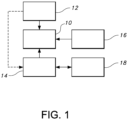
Figure 1 is a schematic representation of a fan with a control for implementing a learning mode of operation; -
Figure 2 is a graphical illustration of one embodiment of the learning mode of operation; and -
Figure 3 is a graphical illustration of another embodiment of the learning mode of operation. - Reference is now made to
Figure 1 , which schematically illustrates one possible embodiment of afan 10 according to the present disclosure. Thefan 10 may comprise any type of fan, such as for example an overhead ceiling fan including a plurality of blades actuated by an associated motor. - The
fan 10 includes at least onesensor 12 to detect an ambient condition, either at the fan location or at a location remote from the fan itself (i.e., not at the precise location where the fan is positioned or within part of the fan itself 10). For example, thesensor 12 may comprise a temperature sensor, which may be part of thefan 10, and may include a sensor for sensing the remote temperature (e.g., a PIR sensor arrangement; see International Patent Application Ser. No.PCT/US15/20998 ) - The sensed temperature may be used by a
controller 14 to control thefan 10, such as by activating it, deactivating it, reversing its direction, or otherwise regulating its speed of operation. - In one embodiment, a
user input 16 is provided for allowing a user to input a fan speed during a learning mode of operation (as contrasted with an automatic mode where the fan speed may be regulated independent of any user input in relation to desired speed). Theinput 16 may comprise a wired or wireless remote control. As one example, theinput 16 may be provided by way of a remote control in the form of a user-specific input device, such as a "smart" phone, computer, or the like, running associated software for communicating the desired value to thefan controller 14 in recognizable form. - In this learning mode, the user inputted speed (e.g., speed A in
Figure 2 ) is recorded in amemory 18 and stored, along with a sensed temperature (e.g., 22,2 degrees Celsius or 72 degrees Fahrenheit) associated with the user input. This recording may be done during an initialization of thefan 10 once installed, or later when a learning mode of operation is selected by the user via theinput 16. - Based on the user selected speed for a given temperature, the
controller 14 may regulate the operation of thefan 10 based on an increase or decrease in temperature from the initial value. For example, if the temperature increases or decreases, thefan 10 may be controlled accordingly (note point B for an increased temperature of 24,4 degrees Celsius or 76 degrees Fahrenheit and a corresponding speed increase). - This adjustment may be done in accordance with a pre-programmed range of values, as represented by
line 20, as shown inFigure 2 . The pre-programmed values may be based on ASHRAE 55 standards stored in thememory 18 in any form (tables, formulae, etc.), or any other stored values obtained using previously obtained data, including possibly empirical data for a particular fan or environment. For the sake of simplicity, these values are shown inFigure 2 as being arranged in a linear fashion, but may be non-linear as well depending on the approach taken. The fan speed values are also shown as being integers correlating to pre-set speeds (e.g.,speed 1 is 10 revolutions per minute,speed 2 is 30 revolutions per minute, etc.), but this is for purposes of illustration only and the speed could be infinitely adjustable within a given range, depending on the sensitivity of the fan motor used. - Later in time, a user (which could be a different user than the one making the initial setting) may adjust the fan speed to a changed speed (e.g., point C), such as by using the
input 16. When this later selection is made, thecontroller 14 associates the changed speed (e.g., point C) with a sensed condition, such as temperature (e.g., 24,4 degrees Celsius or 76 degrees Fahrenheit). Based on the changed speed and the known operating condition, thecontroller 14 may determine that a user has a particular preference different from the pre-programmed value. Accordingly, thecontroller 14 may adjust the speed value for the corresponding condition so that a new mode of operation is created, as indicated by the dashedline 22 inFigure 2 . - Likewise, if an adjustment is made by a user later in time that is different from the adjustment previously made, the
controller 14 may react accordingly. For instance, if a different speed is selected for a sensed temperature (point D for 24,4 degrees Celsius or 76 degrees Fahrenheit), then the values may be adjusted (in this case, to correspond to the original values represented by line 20). However, as should be appreciated, it could also be the case that a new set of values is used for a speed selection that is different from one previously used for a given temperature. - As can further be appreciated, the adjustment or adjustments may be made by a particular user or a different user of the
fan 10. In the case of a different user later making the adjustment, followed by the earlier user returning and making a different adjustment, thefan 10 viacontroller 14 would again learn the difference and make a corresponding adjustment. In this way, the regulation of the fan speed in relation to temperature may be continuously adjusted and updated based on user-specific preferences during the learning mode of operation. - During initialization, it is also possible to instruct the user to set a desired speed for a given temperature, and then a different speed based on a different temperature (e.g., value A in
Figure 2 ). For instance, the user may be prompted to adjust the temperature of the space in which the fan is located, and then adjust the fan speed to the desired level based on the adjusted temperature (e.g., value D inFigure 2 ). Thecontroller 14 may then interpolate using the inputted data for provide a range of speeds based on temperature values (e.g.,line 20 and value B for 23,3 degrees Celsius or 74 degrees Fahrenheit),
which may then be subjected to being altered through future adjustments to the fan speed based on a sensed temperature for as long as the learning mode operation is selected. Instead of during initialization, this second value may also be obtained by simply prompting the user about a desired speed during operation at a later time when the sensed temperature is different from the temperature sensed at the time at which the initial speed value was identified by the user. - A further embodiment is provided by way of
Figure 3 . In this embodiment, the user selects an initial set point of speed for a given condition, such as ambient temperature (e.g., point A inFigure 3 ). Thefan 10 may then operate according to the above embodiment with speed being regulated based on sensed changes in the condition. When a user-selected second speed is inputted, the initial condition is not changed, but rather the user selection at the new condition is simply noted (e.g., point B inFigure 3 ). A calculation (e.g., interpolation) may then be made in order to determine additional values of speed based on the condition(s). As further adjustments are made (e.g., points C and D), the calculation may be likewise adjusted. - While the use of temperature exclusively is described above, it should be appreciated that the same approach could be taken using a different ambient condition, such as humidity. Thus, the speed of the fan could be regulated based on a humidity sensed by a humidity sensor. Of course, it is also possible to regulate the speed based on both temperature and humidity. Indeed, the regulation may be based on a heat index, as determined by the following formula:
Heat Index = -42.379 + 2.04901523T + 10.14333127R - 0.22475541TR - 6.83783 x 10⁻³T2 - 5.481717 x 10⁻²R2 + 1.22874 x 10⁻³T2R + 8.5282 x 10⁻⁴TR2 - 1.99 x 10- 6T2R2 - T - air temperature (F)
- R - relative humidity (percentage)
- Accordingly, a user's initial or later adjustment of the fan speed may be associated with a particular heat index calculated based on a temperature and humidity measurement.
- The conditions in terms of fan speed based on the sensed condition should also be understood to be inexact, such that a temperature being substantially similar to a particular value may be used to regulate the fan at substantially a particular speed, but not necessarily the exact speed. Variations of 10% or more can be expected based on variables such as friction, power, wear, or the like, and will depend on the precise operating conditions encountered in a given situation.
- Having shown and described various embodiments, further adaptations of the apparatuses, methods and systems described herein may be accomplished by appropriate modifications by one of ordinary skill in the art without departing from the scope of the disclosure. Several of such potential modifications have been mentioned, and others will be apparent to those skilled in the art. For instance, the examples, embodiments, geometries, materials, dimensions, ratios, steps, and the like discussed above are illustrative and are not required. The scope of the invention is solely defined by the appended claims and is understood not to be limited to the details of structure and operation shown and described in the specification and drawings.
Claims (11)
- A fan speed regulatory apparatus, comprising:a fan (10); anda controller (14) configured to obtain and learn a first user selected fan speed (A) for a first ambient condition, and for controlling the fan to operate substantially at the first user selected fan speed at the first ambient condition, the controller is further configured for controlling the fan to operate in a first mode of operation (20), wherein in the first mode of operation the controller controls the fan to operate substantially at a first determined speed (B) at a second ambient condition, wherein the second ambient condition is an increase or decrease to the first ambient condition and wherein the first determined speed is determined using a pre-programmed range of values based on the first user selected fan speed and the increase or decrease from the first ambient condition to the second ambient condition,the controller is further configured to obtain and learn a second user selected fan speed (C) for a third ambient condition, wherein the third ambient condition may be the same or different as the second ambient condition and the second user selected fan speed is different to the first determined fan speed determined under the first mode of operation for the third ambient condition, and wherein the controller is configured for:(a) controlling the fan to operate substantially at the second user selected fan speed at the third ambient condition,(b) using the second user selected fan speed at the third ambient condition to create a second mode of operation (22), wherein, in the second mode of operation, the controller controls the fan to operate substantially at a second determined speed at a fourth ambient condition, wherein the fourth ambient condition is an increase or decrease to the third ambient condition and wherein the second determined speed is determined different from the pre-programmed range of values and now based on the second user selected fan speed and the increase or decrease from the third ambient condition to the fourth ambient condition, and(c) controlling the fan to operate in the second mode of operation instead of in the first mode of operation; and the controller is further configured to repeat the above steps based on yet a further user selected fan speed (D) for a further ambient condition, in this way, the controlling of the fan speed in relation to the ambient condition is continuously adjusted and updated based on user-specific preferences.
- An apparatus according to claim 1, wherein in the second mode of operation, the second determined speed at the first ambient condition is different to the first user determined speed at the first ambient condition.
- An apparatus according to claim 1, wherein in the second mode of operation, the second determined speed at the first ambient condition is the same as the first user determined speed at the first ambient condition.
- The apparatus of any one of the foregoing claims, wherein the ambient condition comprises temperature, humidity, or both temperature and humidity.
- The apparatus of any one of the foregoing claims, wherein the controller is configured to automatically activate and deactivate the fan at a particular ambient condition.
- The apparatus of any one of the foregoing claims, wherein the fan is configured to be positioned in a room for causing air movement in the room, and the ambient condition is a temperature within the room.
- The apparatus of any one of the foregoing claims, further including a sensor for sensing the one or more ambient conditions.
- The apparatus of claim 7, wherein the sensor is remote from the fan.
- The apparatus of any one of the foregoing claims, further including a remote controller adapted for communicating wirelessly with the controller (14), the remote controller adapted for providing the user selected fan speeds.
- The apparatus of any one of the foregoing claims, wherein the fan is an overhead fan.
- The apparatus of any one of the foregoing claims, wherein the fan comprises a plurality of fan blades.
Applications Claiming Priority (2)
| Application Number | Priority Date | Filing Date | Title |
|---|---|---|---|
| US201461972619P | 2014-03-31 | 2014-03-31 | |
| PCT/US2015/023582 WO2015153604A1 (en) | 2014-03-31 | 2015-03-31 | Fan with learning mode |
Publications (3)
| Publication Number | Publication Date |
|---|---|
| EP3126677A1 EP3126677A1 (en) | 2017-02-08 |
| EP3126677A4 EP3126677A4 (en) | 2017-12-20 |
| EP3126677B1 true EP3126677B1 (en) | 2025-05-07 |
Family
ID=54241212
Family Applications (1)
| Application Number | Title | Priority Date | Filing Date |
|---|---|---|---|
| EP15773457.5A Active EP3126677B1 (en) | 2014-03-31 | 2015-03-31 | Fan with learning mode |
Country Status (12)
| Country | Link |
|---|---|
| US (2) | US10746185B2 (en) |
| EP (1) | EP3126677B1 (en) |
| JP (1) | JP7136535B2 (en) |
| CN (2) | CN110469525B (en) |
| AU (3) | AU2015240946B2 (en) |
| CA (1) | CA2944431C (en) |
| ES (1) | ES3034666T3 (en) |
| IL (1) | IL248171B (en) |
| MX (1) | MX2016012911A (en) |
| MY (3) | MY208955A (en) |
| SG (2) | SG11201608170RA (en) |
| WO (1) | WO2015153604A1 (en) |
Families Citing this family (7)
| Publication number | Priority date | Publication date | Assignee | Title |
|---|---|---|---|---|
| US9874214B2 (en) | 2014-01-28 | 2018-01-23 | 4Front Engineered Solutions, Inc. | Fan with fan blade mounting structure |
| US11085455B1 (en) * | 2014-08-11 | 2021-08-10 | Delta T, Llc | System for regulating airflow associated with product for sale |
| US11506215B1 (en) | 2014-10-14 | 2022-11-22 | Delta T, Llc | Fan with automatic thermal comfort control |
| US9726192B2 (en) | 2015-03-31 | 2017-08-08 | Assa Abloy Entrance Systems Ab | Fan blades and associated blade tips |
| WO2019126310A1 (en) | 2017-12-20 | 2019-06-27 | Hubbell Incorporated | Connected fan systems |
| CN111550428B (en) * | 2020-05-09 | 2021-11-23 | 成都中邦智能科技有限责任公司 | Control method and system for temperature-sensing variable-frequency fan |
| CN114060296B (en) * | 2020-08-03 | 2023-06-09 | 广东美的环境电器制造有限公司 | Electric fan control method and device, electric fan and computer readable storage medium |
Citations (2)
| Publication number | Priority date | Publication date | Assignee | Title |
|---|---|---|---|---|
| US20090032236A1 (en) * | 2007-08-03 | 2009-02-05 | Honeywell International Inc. | Fan coil thermostat with automatic fan reset |
| US11506215B1 (en) * | 2014-10-14 | 2022-11-22 | Delta T, Llc | Fan with automatic thermal comfort control |
Family Cites Families (67)
| Publication number | Priority date | Publication date | Assignee | Title |
|---|---|---|---|---|
| US4659290A (en) | 1985-03-25 | 1987-04-21 | Control Resources, Inc. | Fan speed controller |
| JPH067022B2 (en) | 1988-02-01 | 1994-01-26 | 三菱電機株式会社 | Air conditioner |
| US5187472A (en) * | 1989-11-03 | 1993-02-16 | Casablanca Industries, Inc. | Remote control system for combined ceiling fan and light fixture |
| US5041825A (en) * | 1989-11-03 | 1991-08-20 | Casablanca Industries, Inc. | Remote control system for combined ceiling fan and light fixture |
| JP2714220B2 (en) | 1990-03-31 | 1998-02-16 | 株式会社東芝 | Ventilation equipment |
| US5189412A (en) | 1990-05-11 | 1993-02-23 | Hunter Fan Company | Remote control for a ceiling fan |
| JP3138058B2 (en) | 1992-05-25 | 2001-02-26 | 東芝キヤリア株式会社 | Ventilation fan control device |
| US5390206A (en) | 1991-10-01 | 1995-02-14 | American Standard Inc. | Wireless communication system for air distribution system |
| US5180333A (en) | 1991-10-28 | 1993-01-19 | Norm Pacific Automation Corp. | Ventilation device adjusted and controlled automatically with movement of human body |
| US5364026A (en) | 1991-11-14 | 1994-11-15 | Control Resources, Inc. | Ventilation fan control |
| US5253804A (en) | 1992-05-12 | 1993-10-19 | Sarazen Jr Paul M | Temperature and humidity sensitive high efficiency exhaust ventilator apparatus |
| US5449275A (en) | 1993-05-11 | 1995-09-12 | Gluszek; Andrzej | Controller and method for operation of electric fan |
| US5528229A (en) * | 1993-10-29 | 1996-06-18 | Hunter Fan Company | Thermostatically controlled remote control for a ceiling fan and light |
| US5449112A (en) | 1994-03-15 | 1995-09-12 | Heitman; Lynn B. | Method and apparatus for monitoring and controlling air handling systems |
| GB9503016D0 (en) | 1995-02-16 | 1995-04-05 | Smiths Industries Plc | Ventilation control |
| US5701117A (en) | 1996-01-18 | 1997-12-23 | Brian Page Platner | Occupancy detector |
| ID16934A (en) | 1996-05-22 | 1997-11-20 | Samsung Electronics Co Ltd | DIRECTION CONTROL DIRECTION AND AIR FLOW SPEED EXTENDED BY AIR CONDUCTING MACHINE AND WORK METHOD |
| US5996898A (en) * | 1998-04-07 | 1999-12-07 | University Of Central Florida | Automatic occupancy and temperature control for ceiling fan operation |
| US6155341A (en) | 1998-12-09 | 2000-12-05 | Carrier Corporation | Continuous fan adjustment method |
| US6201351B1 (en) | 1999-06-11 | 2001-03-13 | The Holmes Group, Inc. | Ceiling fan with a light-sensitive circuit |
| US6912429B1 (en) | 2000-10-19 | 2005-06-28 | Destiny Networks, Inc. | Home automation system and method |
| US6792319B1 (en) | 2000-10-19 | 2004-09-14 | Destiny Networks, Inc. | Home automation system and method |
| US6909921B1 (en) | 2000-10-19 | 2005-06-21 | Destiny Networks, Inc. | Occupancy sensor and method for home automation system |
| US6445984B1 (en) * | 2001-05-25 | 2002-09-03 | The Raymond Corporation | Steer control system for material handling vehicles |
| US6669101B2 (en) | 2001-10-04 | 2003-12-30 | Denso Corporation | Vehicle air conditioner with automatic air-conditioning control having learning function of manual operation |
| US20030225542A1 (en) * | 2002-05-28 | 2003-12-04 | Chang-Ming Liu | Electronic fan capable of automatic fan speed adjustment according to ambient temperature conditions |
| US20030225480A1 (en) | 2002-05-28 | 2003-12-04 | Chang-Ming Liu | Electric fan operable in a breeze-simulating mode |
| US6651895B1 (en) | 2002-08-16 | 2003-11-25 | Delphi Technologies, Inc. | Adaptive automatic climate control method for a motor vehicle |
| JP4093079B2 (en) | 2003-02-25 | 2008-05-28 | 株式会社デンソー | Vehicle air conditioner and control program therefor |
| US20050125083A1 (en) | 2003-11-10 | 2005-06-09 | Kiko Frederick J. | Automation apparatus and methods |
| US6968707B2 (en) | 2003-12-02 | 2005-11-29 | Electrolux Home Products, Inc. | Variable speed, electronically controlled, room air conditioner |
| JP4434998B2 (en) * | 2005-03-09 | 2010-03-17 | 辻川 俊弘 | Indoor temperature control system |
| TWI292654B (en) * | 2005-04-22 | 2008-01-11 | Delta Electronics Inc | Fan control device and method |
| US7392662B2 (en) | 2005-08-11 | 2008-07-01 | Chrysler Llc | Method and system for controlling a climate control system |
| US7747246B2 (en) | 2006-03-02 | 2010-06-29 | At&T Intellectual Property I, L.P. | Environment independent user preference communication |
| JP4914096B2 (en) * | 2006-03-30 | 2012-04-11 | 愛知電機株式会社 | Ventilator for barn |
| US7571865B2 (en) | 2006-10-31 | 2009-08-11 | Tonerhead, Inc. | Wireless temperature control system |
| US7690583B2 (en) | 2007-08-27 | 2010-04-06 | Spring Loop Quail Limited Partnership | Humidity sensor and fan control device |
| US8374725B1 (en) | 2007-11-27 | 2013-02-12 | Joseph David Ols | Climate control |
| CN101939604B (en) | 2008-02-04 | 2013-10-23 | 德尔塔T公司 | Fan system and method of installing and operating the fan system |
| WO2009108228A1 (en) | 2008-02-25 | 2009-09-03 | Kingsdown, Inc. | Systems and methods for controlling a bedroom environment and for providing sleep data |
| US8543244B2 (en) | 2008-12-19 | 2013-09-24 | Oliver Joe Keeling | Heating and cooling control methods and systems |
| CN102292552B (en) | 2009-01-23 | 2014-03-19 | 松下电器产业株式会社 | Ceiling fan |
| JP5375282B2 (en) | 2009-04-07 | 2013-12-25 | パナソニック株式会社 | Ceiling fan |
| US8241008B2 (en) | 2009-02-26 | 2012-08-14 | Standard Microsystems Corporation | RPM controller using drive profiles |
| US8626344B2 (en) | 2009-08-21 | 2014-01-07 | Allure Energy, Inc. | Energy management system and method |
| JP2011122550A (en) * | 2009-12-14 | 2011-06-23 | Toshiba Home Technology Corp | Electric fan |
| US9255720B2 (en) | 2010-04-21 | 2016-02-09 | Honeywell International Inc. | Demand control ventilation system with commissioning and checkout sequence control |
| US8364318B2 (en) | 2010-04-21 | 2013-01-29 | Honeywell International Inc. | Demand control ventilation with fan speed control |
| US9500382B2 (en) | 2010-04-21 | 2016-11-22 | Honeywell International Inc. | Automatic calibration of a demand control ventilation system |
| US8918218B2 (en) | 2010-04-21 | 2014-12-23 | Honeywell International Inc. | Demand control ventilation system with remote monitoring |
| US20110313579A1 (en) | 2010-05-25 | 2011-12-22 | Cheuk Ting Ling | Method for Energy Saving On Electrical Systems Using Habit Oriented Control |
| US9104211B2 (en) | 2010-11-19 | 2015-08-11 | Google Inc. | Temperature controller with model-based time to target calculation and display |
| US8510255B2 (en) | 2010-09-14 | 2013-08-13 | Nest Labs, Inc. | Occupancy pattern detection, estimation and prediction |
| US8843239B2 (en) | 2010-11-19 | 2014-09-23 | Nest Labs, Inc. | Methods, systems, and related architectures for managing network connected thermostats |
| US8606374B2 (en) | 2010-09-14 | 2013-12-10 | Nest Labs, Inc. | Thermodynamic modeling for enclosures |
| US10346275B2 (en) | 2010-11-19 | 2019-07-09 | Google Llc | Attributing causation for energy usage and setpoint changes with a network-connected thermostat |
| US8195313B1 (en) | 2010-11-19 | 2012-06-05 | Nest Labs, Inc. | Thermostat user interface |
| US8850348B2 (en) | 2010-12-31 | 2014-09-30 | Google Inc. | Dynamic device-associated feedback indicative of responsible device usage |
| CN102226563B (en) * | 2011-06-03 | 2013-09-25 | 深圳和而泰智能控制股份有限公司 | Low-cost self-study temperature controller and its methods |
| US9300138B2 (en) | 2011-06-07 | 2016-03-29 | Fujitsu Limited | System and method for managing power consumption |
| US8893032B2 (en) | 2012-03-29 | 2014-11-18 | Google Inc. | User interfaces for HVAC schedule display and modification on smartphone or other space-limited touchscreen device |
| CA2853033C (en) | 2011-10-21 | 2019-07-16 | Nest Labs, Inc. | User-friendly, network connected learning thermostat and related systems and methods |
| US9158310B2 (en) | 2011-12-14 | 2015-10-13 | International Business Machines Corporation | Integrating a data center thermal control system and individual fan controllers for controlling a thermal environment in a data center room |
| US8620841B1 (en) | 2012-08-31 | 2013-12-31 | Nest Labs, Inc. | Dynamic distributed-sensor thermostat network for forecasting external events |
| US8594850B1 (en) | 2012-09-30 | 2013-11-26 | Nest Labs, Inc. | Updating control software on a network-connected HVAC controller |
| CN203269283U (en) * | 2013-04-12 | 2013-11-06 | 快意电梯股份有限公司 | Elevator cab lighting, fan and air-conditioner energy-saving control system |
-
2015
- 2015-03-31 EP EP15773457.5A patent/EP3126677B1/en active Active
- 2015-03-31 CN CN201910692245.8A patent/CN110469525B/en active Active
- 2015-03-31 MX MX2016012911A patent/MX2016012911A/en unknown
- 2015-03-31 US US15/300,844 patent/US10746185B2/en active Active
- 2015-03-31 AU AU2015240946A patent/AU2015240946B2/en active Active
- 2015-03-31 WO PCT/US2015/023582 patent/WO2015153604A1/en not_active Ceased
- 2015-03-31 ES ES15773457T patent/ES3034666T3/en active Active
- 2015-03-31 IL IL248171A patent/IL248171B/en unknown
- 2015-03-31 MY MYPI2021000141A patent/MY208955A/en unknown
- 2015-03-31 SG SG11201608170RA patent/SG11201608170RA/en unknown
- 2015-03-31 SG SG10201808483TA patent/SG10201808483TA/en unknown
- 2015-03-31 JP JP2016560348A patent/JP7136535B2/en active Active
- 2015-03-31 CA CA2944431A patent/CA2944431C/en active Active
- 2015-03-31 CN CN201580026727.XA patent/CN106460861B/en active Active
- 2015-03-31 MY MYPI2016703618A patent/MY174474A/en unknown
- 2015-03-31 MY MYPI2019007268A patent/MY185643A/en unknown
-
2019
- 2019-03-08 AU AU2019201620A patent/AU2019201620B2/en active Active
-
2020
- 2020-08-17 US US16/995,148 patent/US11378087B2/en active Active
-
2021
- 2021-01-12 AU AU2021200150A patent/AU2021200150B2/en active Active
Patent Citations (2)
| Publication number | Priority date | Publication date | Assignee | Title |
|---|---|---|---|---|
| US20090032236A1 (en) * | 2007-08-03 | 2009-02-05 | Honeywell International Inc. | Fan coil thermostat with automatic fan reset |
| US11506215B1 (en) * | 2014-10-14 | 2022-11-22 | Delta T, Llc | Fan with automatic thermal comfort control |
Also Published As
| Publication number | Publication date |
|---|---|
| AU2021200150A1 (en) | 2021-03-18 |
| SG11201608170RA (en) | 2016-10-28 |
| IL248171A0 (en) | 2016-11-30 |
| MX2016012911A (en) | 2017-05-01 |
| CN106460861A (en) | 2017-02-22 |
| AU2019201620A1 (en) | 2019-04-04 |
| AU2019201620B2 (en) | 2020-10-15 |
| US20170016451A1 (en) | 2017-01-19 |
| MY174474A (en) | 2020-04-21 |
| CA2944431A1 (en) | 2015-10-08 |
| MY208955A (en) | 2025-06-12 |
| CA2944431C (en) | 2023-03-21 |
| AU2015240946B2 (en) | 2019-03-28 |
| EP3126677A4 (en) | 2017-12-20 |
| JP2017511438A (en) | 2017-04-20 |
| CN110469525B (en) | 2022-02-18 |
| ES3034666T3 (en) | 2025-08-21 |
| MY185643A (en) | 2021-05-27 |
| EP3126677A1 (en) | 2017-02-08 |
| US10746185B2 (en) | 2020-08-18 |
| US11378087B2 (en) | 2022-07-05 |
| AU2015240946A1 (en) | 2016-11-10 |
| US20210033098A1 (en) | 2021-02-04 |
| JP7136535B2 (en) | 2022-09-13 |
| AU2021200150B2 (en) | 2022-11-03 |
| CN106460861B (en) | 2019-08-06 |
| IL248171B (en) | 2022-09-01 |
| WO2015153604A1 (en) | 2015-10-08 |
| SG10201808483TA (en) | 2018-11-29 |
| CN110469525A (en) | 2019-11-19 |
Similar Documents
| Publication | Publication Date | Title |
|---|---|---|
| AU2021200150B2 (en) | Fan with Learning Mode | |
| US10126010B2 (en) | Controlling system for environmental comfort degree and controlling method of the controlling system | |
| US10900682B2 (en) | HVAC controller with indoor air quality scheduling | |
| US10635119B2 (en) | Method and system for configuring wireless sensors in an HVAC system | |
| US20050119766A1 (en) | Controller interface with menu schedule override | |
| US20130245838A1 (en) | Hvac controller and remote control unit | |
| US20120078420A1 (en) | Fan speed control | |
| WO2009073496A2 (en) | Hvac controller | |
| TW264588B (en) | Thermostatically controlled remote control for a ceiling fan and light | |
| JP2015031473A (en) | Air conditioner | |
| US11506215B1 (en) | Fan with automatic thermal comfort control | |
| CA3042575C (en) | Method and environment controller using a neural network for bypassing a legacy environment control software module | |
| WO2015141118A1 (en) | Air-blowing control system and air-blowing control program | |
| US10724753B2 (en) | System and method for operating a variable speed compressor | |
| HK1232933A1 (en) | Fan with learning mode | |
| HK1232933B (en) | Fan with learning mode | |
| JPWO2022097225A5 (en) | ||
| EP3067634B1 (en) | A method of controlling the ventilation of one or more room spaces and a ventilation level control |
Legal Events
| Date | Code | Title | Description |
|---|---|---|---|
| STAA | Information on the status of an ep patent application or granted ep patent |
Free format text: STATUS: THE INTERNATIONAL PUBLICATION HAS BEEN MADE |
|
| PUAI | Public reference made under article 153(3) epc to a published international application that has entered the european phase |
Free format text: ORIGINAL CODE: 0009012 |
|
| STAA | Information on the status of an ep patent application or granted ep patent |
Free format text: STATUS: REQUEST FOR EXAMINATION WAS MADE |
|
| 17P | Request for examination filed |
Effective date: 20161019 |
|
| AK | Designated contracting states |
Kind code of ref document: A1 Designated state(s): AL AT BE BG CH CY CZ DE DK EE ES FI FR GB GR HR HU IE IS IT LI LT LU LV MC MK MT NL NO PL PT RO RS SE SI SK SM TR |
|
| AX | Request for extension of the european patent |
Extension state: BA ME |
|
| DAV | Request for validation of the european patent (deleted) | ||
| DAX | Request for extension of the european patent (deleted) | ||
| A4 | Supplementary search report drawn up and despatched |
Effective date: 20171117 |
|
| RIC1 | Information provided on ipc code assigned before grant |
Ipc: F04D 25/08 20060101AFI20171113BHEP Ipc: F04D 27/00 20060101ALI20171113BHEP Ipc: F24F 11/00 20060101ALI20171113BHEP |
|
| STAA | Information on the status of an ep patent application or granted ep patent |
Free format text: STATUS: EXAMINATION IS IN PROGRESS |
|
| 17Q | First examination report despatched |
Effective date: 20190514 |
|
| RAP3 | Party data changed (applicant data changed or rights of an application transferred) |
Owner name: DELTA T, LLC |
|
| REG | Reference to a national code |
Ref country code: DE Ref legal event code: R079 Free format text: PREVIOUS MAIN CLASS: F04D0027000000 Ipc: F04D0025080000 Ref country code: DE Ref legal event code: R079 Ref document number: 602015091597 Country of ref document: DE Free format text: PREVIOUS MAIN CLASS: F04D0027000000 Ipc: F04D0025080000 |
|
| GRAP | Despatch of communication of intention to grant a patent |
Free format text: ORIGINAL CODE: EPIDOSNIGR1 |
|
| STAA | Information on the status of an ep patent application or granted ep patent |
Free format text: STATUS: GRANT OF PATENT IS INTENDED |
|
| RIC1 | Information provided on ipc code assigned before grant |
Ipc: F24F 120/20 20180101ALN20241104BHEP Ipc: F24F 110/20 20180101ALN20241104BHEP Ipc: F24F 110/10 20180101ALN20241104BHEP Ipc: F24F 11/65 20180101ALI20241104BHEP Ipc: F24F 11/77 20180101ALI20241104BHEP Ipc: F24F 11/30 20180101ALI20241104BHEP Ipc: F04D 27/00 20060101ALI20241104BHEP Ipc: F04D 25/08 20060101AFI20241104BHEP |
|
| INTG | Intention to grant announced |
Effective date: 20241119 |
|
| GRAS | Grant fee paid |
Free format text: ORIGINAL CODE: EPIDOSNIGR3 |
|
| GRAA | (expected) grant |
Free format text: ORIGINAL CODE: 0009210 |
|
| STAA | Information on the status of an ep patent application or granted ep patent |
Free format text: STATUS: THE PATENT HAS BEEN GRANTED |
|
| AK | Designated contracting states |
Kind code of ref document: B1 Designated state(s): AL AT BE BG CH CY CZ DE DK EE ES FI FR GB GR HR HU IE IS IT LI LT LU LV MC MK MT NL NO PL PT RO RS SE SI SK SM TR |
|
| REG | Reference to a national code |
Ref country code: GB Ref legal event code: FG4D |
|
| REG | Reference to a national code |
Ref country code: CH Ref legal event code: EP |
|
| REG | Reference to a national code |
Ref country code: DE Ref legal event code: R096 Ref document number: 602015091597 Country of ref document: DE |
|
| P01 | Opt-out of the competence of the unified patent court (upc) registered |
Free format text: CASE NUMBER: APP_18756/2025 Effective date: 20250417 |
|
| REG | Reference to a national code |
Ref country code: IE Ref legal event code: FG4D |
|
| REG | Reference to a national code |
Ref country code: ES Ref legal event code: FG2A Ref document number: 3034666 Country of ref document: ES Kind code of ref document: T3 Effective date: 20250821 |
|
| REG | Reference to a national code |
Ref country code: NL Ref legal event code: MP Effective date: 20250507 |
|
| PG25 | Lapsed in a contracting state [announced via postgrant information from national office to epo] |
Ref country code: FI Free format text: LAPSE BECAUSE OF FAILURE TO SUBMIT A TRANSLATION OF THE DESCRIPTION OR TO PAY THE FEE WITHIN THE PRESCRIBED TIME-LIMIT Effective date: 20250507 Ref country code: PT Free format text: LAPSE BECAUSE OF FAILURE TO SUBMIT A TRANSLATION OF THE DESCRIPTION OR TO PAY THE FEE WITHIN THE PRESCRIBED TIME-LIMIT Effective date: 20250908 |
|
| REG | Reference to a national code |
Ref country code: LT Ref legal event code: MG9D |
|
| PG25 | Lapsed in a contracting state [announced via postgrant information from national office to epo] |
Ref country code: NO Free format text: LAPSE BECAUSE OF FAILURE TO SUBMIT A TRANSLATION OF THE DESCRIPTION OR TO PAY THE FEE WITHIN THE PRESCRIBED TIME-LIMIT Effective date: 20250807 Ref country code: GR Free format text: LAPSE BECAUSE OF FAILURE TO SUBMIT A TRANSLATION OF THE DESCRIPTION OR TO PAY THE FEE WITHIN THE PRESCRIBED TIME-LIMIT Effective date: 20250808 |
|
| PG25 | Lapsed in a contracting state [announced via postgrant information from national office to epo] |
Ref country code: NL Free format text: LAPSE BECAUSE OF FAILURE TO SUBMIT A TRANSLATION OF THE DESCRIPTION OR TO PAY THE FEE WITHIN THE PRESCRIBED TIME-LIMIT Effective date: 20250507 Ref country code: PL Free format text: LAPSE BECAUSE OF FAILURE TO SUBMIT A TRANSLATION OF THE DESCRIPTION OR TO PAY THE FEE WITHIN THE PRESCRIBED TIME-LIMIT Effective date: 20250507 |
|
| REG | Reference to a national code |
Ref country code: AT Ref legal event code: MK05 Ref document number: 1792733 Country of ref document: AT Kind code of ref document: T Effective date: 20250507 |
|
| PG25 | Lapsed in a contracting state [announced via postgrant information from national office to epo] |
Ref country code: BG Free format text: LAPSE BECAUSE OF FAILURE TO SUBMIT A TRANSLATION OF THE DESCRIPTION OR TO PAY THE FEE WITHIN THE PRESCRIBED TIME-LIMIT Effective date: 20250507 |
|
| PG25 | Lapsed in a contracting state [announced via postgrant information from national office to epo] |
Ref country code: HR Free format text: LAPSE BECAUSE OF FAILURE TO SUBMIT A TRANSLATION OF THE DESCRIPTION OR TO PAY THE FEE WITHIN THE PRESCRIBED TIME-LIMIT Effective date: 20250507 |
|
| PG25 | Lapsed in a contracting state [announced via postgrant information from national office to epo] |
Ref country code: AT Free format text: LAPSE BECAUSE OF FAILURE TO SUBMIT A TRANSLATION OF THE DESCRIPTION OR TO PAY THE FEE WITHIN THE PRESCRIBED TIME-LIMIT Effective date: 20250507 |
|
| PG25 | Lapsed in a contracting state [announced via postgrant information from national office to epo] |
Ref country code: RS Free format text: LAPSE BECAUSE OF FAILURE TO SUBMIT A TRANSLATION OF THE DESCRIPTION OR TO PAY THE FEE WITHIN THE PRESCRIBED TIME-LIMIT Effective date: 20250807 |
|
| PG25 | Lapsed in a contracting state [announced via postgrant information from national office to epo] |
Ref country code: IS Free format text: LAPSE BECAUSE OF FAILURE TO SUBMIT A TRANSLATION OF THE DESCRIPTION OR TO PAY THE FEE WITHIN THE PRESCRIBED TIME-LIMIT Effective date: 20250907 |
|
| PG25 | Lapsed in a contracting state [announced via postgrant information from national office to epo] |
Ref country code: LV Free format text: LAPSE BECAUSE OF FAILURE TO SUBMIT A TRANSLATION OF THE DESCRIPTION OR TO PAY THE FEE WITHIN THE PRESCRIBED TIME-LIMIT Effective date: 20250507 |
|
| PG25 | Lapsed in a contracting state [announced via postgrant information from national office to epo] |
Ref country code: DK Free format text: LAPSE BECAUSE OF FAILURE TO SUBMIT A TRANSLATION OF THE DESCRIPTION OR TO PAY THE FEE WITHIN THE PRESCRIBED TIME-LIMIT Effective date: 20250507 Ref country code: SM Free format text: LAPSE BECAUSE OF FAILURE TO SUBMIT A TRANSLATION OF THE DESCRIPTION OR TO PAY THE FEE WITHIN THE PRESCRIBED TIME-LIMIT Effective date: 20250507 |
|
| PG25 | Lapsed in a contracting state [announced via postgrant information from national office to epo] |
Ref country code: CZ Free format text: LAPSE BECAUSE OF FAILURE TO SUBMIT A TRANSLATION OF THE DESCRIPTION OR TO PAY THE FEE WITHIN THE PRESCRIBED TIME-LIMIT Effective date: 20250507 |
|
| PG25 | Lapsed in a contracting state [announced via postgrant information from national office to epo] |
Ref country code: EE Free format text: LAPSE BECAUSE OF FAILURE TO SUBMIT A TRANSLATION OF THE DESCRIPTION OR TO PAY THE FEE WITHIN THE PRESCRIBED TIME-LIMIT Effective date: 20250507 |
|
| PG25 | Lapsed in a contracting state [announced via postgrant information from national office to epo] |
Ref country code: RO Free format text: LAPSE BECAUSE OF FAILURE TO SUBMIT A TRANSLATION OF THE DESCRIPTION OR TO PAY THE FEE WITHIN THE PRESCRIBED TIME-LIMIT Effective date: 20250507 Ref country code: SK Free format text: LAPSE BECAUSE OF FAILURE TO SUBMIT A TRANSLATION OF THE DESCRIPTION OR TO PAY THE FEE WITHIN THE PRESCRIBED TIME-LIMIT Effective date: 20250507 |
|
| REG | Reference to a national code |
Ref country code: DE Ref legal event code: R097 Ref document number: 602015091597 Country of ref document: DE |
|
| PLBE | No opposition filed within time limit |
Free format text: ORIGINAL CODE: 0009261 |
|
| STAA | Information on the status of an ep patent application or granted ep patent |
Free format text: STATUS: NO OPPOSITION FILED WITHIN TIME LIMIT |
|
| REG | Reference to a national code |
Ref country code: CH Ref legal event code: L10 Free format text: ST27 STATUS EVENT CODE: U-0-0-L10-L00 (AS PROVIDED BY THE NATIONAL OFFICE) Effective date: 20260318 |
|
| 26N | No opposition filed |
Effective date: 20260210 |