EP3126661B1 - Solid propellant rocket motor - Google Patents
Solid propellant rocket motor Download PDFInfo
- Publication number
- EP3126661B1 EP3126661B1 EP15724020.1A EP15724020A EP3126661B1 EP 3126661 B1 EP3126661 B1 EP 3126661B1 EP 15724020 A EP15724020 A EP 15724020A EP 3126661 B1 EP3126661 B1 EP 3126661B1
- Authority
- EP
- European Patent Office
- Prior art keywords
- motor
- casing
- blocking
- portions
- abutting surface
- Prior art date
- Legal status (The legal status is an assumption and is not a legal conclusion. Google has not performed a legal analysis and makes no representation as to the accuracy of the status listed.)
- Active
Links
Images

Classifications
-
- F—MECHANICAL ENGINEERING; LIGHTING; HEATING; WEAPONS; BLASTING
- F02—COMBUSTION ENGINES; HOT-GAS OR COMBUSTION-PRODUCT ENGINE PLANTS
- F02K—JET-PROPULSION PLANTS
- F02K9/00—Rocket-engine plants, i.e. plants carrying both fuel and oxidant therefor; Control thereof
- F02K9/08—Rocket-engine plants, i.e. plants carrying both fuel and oxidant therefor; Control thereof using solid propellants
- F02K9/32—Constructional parts; Details not otherwise provided for
- F02K9/36—Propellant charge supports
-
- F—MECHANICAL ENGINEERING; LIGHTING; HEATING; WEAPONS; BLASTING
- F02—COMBUSTION ENGINES; HOT-GAS OR COMBUSTION-PRODUCT ENGINE PLANTS
- F02K—JET-PROPULSION PLANTS
- F02K7/00—Plants in which the working fluid is used in a jet only, i.e. the plants not having a turbine or other engine driving a compressor or a ducted fan; Control thereof
- F02K7/10—Plants in which the working fluid is used in a jet only, i.e. the plants not having a turbine or other engine driving a compressor or a ducted fan; Control thereof characterised by having ram-action compression, i.e. aero-thermo-dynamic-ducts or ram-jet engines
- F02K7/105—Plants in which the working fluid is used in a jet only, i.e. the plants not having a turbine or other engine driving a compressor or a ducted fan; Control thereof characterised by having ram-action compression, i.e. aero-thermo-dynamic-ducts or ram-jet engines using a solid fuel
-
- F—MECHANICAL ENGINEERING; LIGHTING; HEATING; WEAPONS; BLASTING
- F02—COMBUSTION ENGINES; HOT-GAS OR COMBUSTION-PRODUCT ENGINE PLANTS
- F02K—JET-PROPULSION PLANTS
- F02K9/00—Rocket-engine plants, i.e. plants carrying both fuel and oxidant therefor; Control thereof
- F02K9/08—Rocket-engine plants, i.e. plants carrying both fuel and oxidant therefor; Control thereof using solid propellants
- F02K9/10—Shape or structure of solid propellant charges
-
- F—MECHANICAL ENGINEERING; LIGHTING; HEATING; WEAPONS; BLASTING
- F02—COMBUSTION ENGINES; HOT-GAS OR COMBUSTION-PRODUCT ENGINE PLANTS
- F02K—JET-PROPULSION PLANTS
- F02K9/00—Rocket-engine plants, i.e. plants carrying both fuel and oxidant therefor; Control thereof
- F02K9/08—Rocket-engine plants, i.e. plants carrying both fuel and oxidant therefor; Control thereof using solid propellants
- F02K9/26—Burning control
-
- F—MECHANICAL ENGINEERING; LIGHTING; HEATING; WEAPONS; BLASTING
- F02—COMBUSTION ENGINES; HOT-GAS OR COMBUSTION-PRODUCT ENGINE PLANTS
- F02K—JET-PROPULSION PLANTS
- F02K9/00—Rocket-engine plants, i.e. plants carrying both fuel and oxidant therefor; Control thereof
- F02K9/08—Rocket-engine plants, i.e. plants carrying both fuel and oxidant therefor; Control thereof using solid propellants
- F02K9/32—Constructional parts; Details not otherwise provided for
- F02K9/34—Casings; Combustion chambers; Liners thereof
- F02K9/343—Joints, connections, seals therefor
-
- F—MECHANICAL ENGINEERING; LIGHTING; HEATING; WEAPONS; BLASTING
- F02—COMBUSTION ENGINES; HOT-GAS OR COMBUSTION-PRODUCT ENGINE PLANTS
- F02K—JET-PROPULSION PLANTS
- F02K9/00—Rocket-engine plants, i.e. plants carrying both fuel and oxidant therefor; Control thereof
- F02K9/08—Rocket-engine plants, i.e. plants carrying both fuel and oxidant therefor; Control thereof using solid propellants
- F02K9/32—Constructional parts; Details not otherwise provided for
- F02K9/38—Safety devices, e.g. to prevent accidental ignition
-
- F—MECHANICAL ENGINEERING; LIGHTING; HEATING; WEAPONS; BLASTING
- F02—COMBUSTION ENGINES; HOT-GAS OR COMBUSTION-PRODUCT ENGINE PLANTS
- F02K—JET-PROPULSION PLANTS
- F02K9/00—Rocket-engine plants, i.e. plants carrying both fuel and oxidant therefor; Control thereof
- F02K9/80—Rocket-engine plants, i.e. plants carrying both fuel and oxidant therefor; Control thereof characterised by thrust or thrust vector control
- F02K9/86—Rocket-engine plants, i.e. plants carrying both fuel and oxidant therefor; Control thereof characterised by thrust or thrust vector control using nozzle throats of adjustable cross- section
-
- F—MECHANICAL ENGINEERING; LIGHTING; HEATING; WEAPONS; BLASTING
- F05—INDEXING SCHEMES RELATING TO ENGINES OR PUMPS IN VARIOUS SUBCLASSES OF CLASSES F01-F04
- F05D—INDEXING SCHEME FOR ASPECTS RELATING TO NON-POSITIVE-DISPLACEMENT MACHINES OR ENGINES, GAS-TURBINES OR JET-PROPULSION PLANTS
- F05D2220/00—Application
- F05D2220/80—Application in supersonic vehicles excluding hypersonic vehicles or ram, scram or rocket propulsion
-
- F—MECHANICAL ENGINEERING; LIGHTING; HEATING; WEAPONS; BLASTING
- F05—INDEXING SCHEMES RELATING TO ENGINES OR PUMPS IN VARIOUS SUBCLASSES OF CLASSES F01-F04
- F05D—INDEXING SCHEME FOR ASPECTS RELATING TO NON-POSITIVE-DISPLACEMENT MACHINES OR ENGINES, GAS-TURBINES OR JET-PROPULSION PLANTS
- F05D2250/00—Geometry
- F05D2250/40—Movement of components
- F05D2250/41—Movement of components with one degree of freedom
- F05D2250/411—Movement of components with one degree of freedom in rotation
-
- F—MECHANICAL ENGINEERING; LIGHTING; HEATING; WEAPONS; BLASTING
- F05—INDEXING SCHEMES RELATING TO ENGINES OR PUMPS IN VARIOUS SUBCLASSES OF CLASSES F01-F04
- F05D—INDEXING SCHEME FOR ASPECTS RELATING TO NON-POSITIVE-DISPLACEMENT MACHINES OR ENGINES, GAS-TURBINES OR JET-PROPULSION PLANTS
- F05D2260/00—Function
- F05D2260/30—Retaining components in desired mutual position
-
- F—MECHANICAL ENGINEERING; LIGHTING; HEATING; WEAPONS; BLASTING
- F05—INDEXING SCHEMES RELATING TO ENGINES OR PUMPS IN VARIOUS SUBCLASSES OF CLASSES F01-F04
- F05D—INDEXING SCHEME FOR ASPECTS RELATING TO NON-POSITIVE-DISPLACEMENT MACHINES OR ENGINES, GAS-TURBINES OR JET-PROPULSION PLANTS
- F05D2300/00—Materials; Properties thereof
- F05D2300/50—Intrinsic material properties or characteristics
- F05D2300/501—Elasticity
Definitions
- the present invention concerns a solid propellant rocket motor.
- solid propellant motors are used both in the military field and in the field of space launchers.
- the known motors comprise an outer casing, which houses a predefined annular mass of solid propellant and is closed at the opposite ends by two closing heads distinct from the casing.
- One of said heads carries an ignition device for igniting the solid propellant while the other supports a nozzle for outlet of the exhaust gases resulting from combustion of the propellant inside the casing.
- Loading of the solid propellant in the casing, assembly of the heads and connection of the heads to the casing and any subsequent storage are generally performed in sites or on different platforms normally well away from the launch platform.
- the heads are initially coupled to the casing by means of distinct temporary connecting elements with predefined breaking points which, in the event of spontaneous ignition, rupture due to the action generated by the pressure of the gases inside the casing, permitting an increase in the outflow section of the gases towards the outside. This reduces the pressure inside the motor combustion chamber and, consequently, the thrust generated.
- a condition of safety at spontaneous ignition is never fully achieved when several motors are stacked on top of one another, as in the case of multistage launchers.
- the permanent connecting elements must be inserted before stacking one motor on top of the motor below which, at this point, is ready for ignition and therefore has the same problems as described before concerning prevention of the effects of spontaneous ignition.
- a propeller with closing heads screwed on the ends of an intermediate tubular body is described in JP document S 604 78 52 .
- the object of the present invention is to provide a solid propellant rocket motor which solves the above problems simply and inexpensively.
- a solid propellant rocket motor is provided, as claimed in claim 1.
- the number 1 indicates, as a whole, a solid propellant rocket motor.
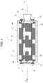
- the motor 1 comprises, in the particular example described, an elongated cylindrical tubular casing 3, which has a longitudinal axis 4 and houses, in a per se known manner, a mass 5 of solid propellant delimiting a central channel 6 defining an elongated combustion chamber along the axis 4.
- the casing 3 comprises, in turn, a lateral wall 7 and two frontal walls 8 and 9, which delimit respective passages 10 closed by respective heads 11 and 12.
- the head 11 carries an ignition assembly 14, known per se and not described in detail, arranged in an end section of the duct 6 to ignite the solid propellant 5, while the head 12 carries a nozzle 15 for outlet of the exhaust gases resulting from combustion of the propellant 5 inside the casing 3, also known per se and not described in detail.
- the heads 11 and 12 are connected to the respective frontal walls 8 and 9 by respective connection assemblies 16 that can be configured from the outside to arrange the motor 1 in an operating or launching configuration or in a safety condition, or in an assembly condition, as will be described in detail below.
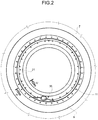
- each connection assembly 16 comprises a circumferential groove 18 obtained coaxially to the axis 4 inside the respective wall 8,9 through a surface 8A,9A delimiting the relative opening.
- each groove 18 has in radial semi-section a rectangular shape elongated in a radial direction and is delimited by a bottom surface 19 and by an axial abutment surface 20.
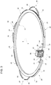
- each connecting assembly 16 further comprises an open circular annular body 21, which extends coaxially to the axis 4 and to the outside of the relative head 11,12 and is made of elastically deformable material, for example steel or aluminium alloy.
- the body 21 is shaped like an ordinary Seeger ring, is deformable on a plane orthogonal to the axis 4 and comprises a curved intermediate portion 22 and two free end portions 23 adjacent to and facing each other.
- the annular body 21 has, in radial semi-section, a shape complementary to the groove 19 and external dimensions such as to engage the groove 19 itself sliding in a radial direction.
- the annular body 21 is laterally delimited by a cylindrical perimeter surface 24 facing the bottom wall 19 of the groove 18 and axially by two flat surfaces 25 and 26 parallel to each other and orthogonal to the axis 4, the surface 26 of which is arranged abutting against the relative head 11,12, while the surface 25 is adapted to be arranged abutting against, or on the outside of, the surface 20 according to the deformation of the annular body 21.
- the body 21 carries a plurality of radial appendixes 28, which are distributed at a predefined pitch on the perimeter surface 24, protrude from the surface 24 and in this specific case constitute with the annular body 21 part of a body made in one single piece.
- the appendixes 28 are welded on the surface 24.
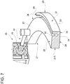
- Each appendix 28 has a resistant radial section which is smaller than the section of the annular body 21, as can be clearly seen from figure 7 , and is axially delimited by two axial surfaces 29 and 30 coplanar with the surface 25 and with the surface 26 respectively ( fig. 7 ).
- Each appendix 28 is then laterally delimited by a cylindrical surface 31 parallel to and facing the bottom surface 19 of the groove 18.
- each appendix 28 has in radial section an upturned L shape and comprises two curved walls 33 and 34 orthogonal to each other and delimiting with the surface 24 a curved axial channel 32 having an axial opening facing outwards.
- each assembly 16 further comprises a device 35 for inflexion or elastic deformation of the annular body 21.
- each device 35 is arranged between the relative end portions 23 and outside the relative head 11,12.
- Each device 35 comprises an actuation assembly 36, in turn comprising a frame 37 permanently connected to the relative head 11,12 between the terminal portions 23, a worm 40 coupled to the frame 37 to rotate about an axis 41 orthogonal to the axis 4 and a helical wheel 38 engaging with the worm 40 and revolving about an axis 39 tangential and orthogonal to the axes 4 and 41.
- the worm 40 is manually activated by an operator from the outside of the casing 37 and the head 11,12 by means of an appropriate wrench, not illustrated, which is inserted in the hollow hub of the worm 40.
- the worm 40 is driven by an electric, hydraulic or pneumatic motor controlled by a dedicated control unit, not illustrated, which can be activated in remote mode.
- the opposite axial ends of the wheel end 39 protrude outside the casing 37 and are each connected to a relative end portion 23 by means of a respective corner joint 43, for example of cardan type, and via a relative screw/screw-nut assembly 44.
- Each assembly 44 comprises a screw 45 angularly integral with the relative joint 43 and a screw-nut 46 hinged to the respective portion 23 in a position angularly fixed by means of a pin 47 parallel to the axis 4.
- the assembly 16 comprises, lastly, a plurality of pairs 48 of elastic fins 49 arranged along the outer periphery of the annular body 21 between two consecutive appendixes.
- the fins 49 of each pair 48 of fins are curved fins with concavity facing towards the surface 24 of the annular body 21 and are integrally connected to the surface 24 itself, for example, by welding or bolting. In a non-deformed condition, the fins 49 of each pair 48 of fins extend from the surface 24 towards each other and towards the outside, whereas in a condition of maximum deformation they envelop the surface 24 without coming into contact with each other.
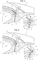
- the fins 49 have, in a direction parallel to the axis 4, dimensions such as to engage by sliding in the groove 18 to maintain, when arranged in a non-deformed or partially deformed condition, the annular body 21 in an assembly position, illustrated in figure 4 , in which the annular body 21 extends in a position coaxial to the axis 4 and the appendixes 28 are arranged outside the groove 18.
- the annular body 21 is progressively deformed spacing its end portions 23 from each other. Following said spacing, the fins 49 elastically deform, moving progressively closer to the annular body 21 and the appendixes 28 are progressively inserted inside the groove 18. The deformation of the annular body 21 continues until the walls 33 are completely arranged abutting against the surface 20 and the channels 32 communicate axially with the outside, as illustrated in figure 5 .
- the motor 1 is arranged in a safe condition in which it is not able to develop the maximum rated power.
- the head 11, while closing to seal the casing 3 is blocked with respect to the casing 3 by deliberately weakened or breakable portions, so that a sudden pressure increase inside the casing 3 resulting from accidental ignition of the solid propellant 5 is interrupted, allowing the head 11,12 to disengage from the casing 3 when the pressure value inside said casing 3 exceeds a threshold value at the preset design stage, expediently in the order of 10 bar or equal to a predefined percentage of the motor operating pressure.
- the motor 1 is set to a propulsion position by spacing, again via device 35, the portions 23 from each other and elastically deforming the body 21 until bringing an outer perimeter portion 21A of the annular body 21 inside the groove 18, abutting against the surface 20 of the groove 18, as indicated in figure 6 .
- the head 11 is permanently blocked with respect to the casing 3 regardless of the pressure present inside the casing 3 since the annular portion 21A has a much bigger resistant section than the resistant section of the appendixes 28. In said condition, the motor 1 is ready to be used.
- the devices 16 described allow the motor 1 to be configured extremely rapidly and particularly easily.
- the devices 16 allow the motor 1 to be set to a safe condition or a propulsion operating condition in addition to an assembly position by simply operating an actuator assembly arranged on the outer periphery of the casing 3 and, therefore, without the need to disassemble elements and re-fit others in their place, as in the solutions known today.
- the use of the devices 16 described is particularly advantageous in cases in which two or more motors 1 are stacked on top of one another since, unlike the known solutions, the various motors are set to their operating condition simultaneously and only after all the other assembly and preparation operations have been completed, thus increasing safety on the launch platform.
- the appendixes 28 and the portion 21A could be carried by a support and movement body different in construction terms from the elastic body 21 but always such as to selectively arrange the blocking portions with different strength between at least one of the heads 11,12 and the casing 3.
- both the weakened appendixes 28 and the fins 49 provided to maintain the portions with different strength in a reference position around the axis 4 could be different in terms of geometry and/or number.
- the motor 1 described could comprise one single configurable device 16.
Landscapes
- Engineering & Computer Science (AREA)
- Chemical & Material Sciences (AREA)
- Combustion & Propulsion (AREA)
- Mechanical Engineering (AREA)
- General Engineering & Computer Science (AREA)
- Connection Of Motors, Electrical Generators, Mechanical Devices, And The Like (AREA)
- Actuator (AREA)
- Structures Of Non-Positive Displacement Pumps (AREA)
Description
- The present invention concerns a solid propellant rocket motor.
- As is known, solid propellant motors are used both in the military field and in the field of space launchers.
- In both applications, the known motors comprise an outer casing, which houses a predefined annular mass of solid propellant and is closed at the opposite ends by two closing heads distinct from the casing.
- One of said heads carries an ignition device for igniting the solid propellant while the other supports a nozzle for outlet of the exhaust gases resulting from combustion of the propellant inside the casing.
- Loading of the solid propellant in the casing, assembly of the heads and connection of the heads to the casing and any subsequent storage are generally performed in sites or on different platforms normally well away from the launch platform.
- Both in the storage period and during transport towards the launch platform and in any case for the entire launch preparation phase on the same platform, external causes such as an increase in temperature, an impact or an electrostatic discharge, for example, can cause a sudden and uncontrolled ignition of the solid fuel with devastating effects in terms of financial losses or loss of human life. For this reason, the heads are initially coupled to the casing by means of distinct temporary connecting elements with predefined breaking points which, in the event of spontaneous ignition, rupture due to the action generated by the pressure of the gases inside the casing, permitting an increase in the outflow section of the gases towards the outside. This reduces the pressure inside the motor combustion chamber and, consequently, the thrust generated.
- When all the preparatory operations have been positively completed on the launch platform, the temporary connecting elements are removed and replaced with permanent structural elements which permanently connect the heads to the casing, enabling the motor for flight.
- The removal of the temporary connecting elements and assembly of the permanent ones involves complications and obliges the technicians in charge to work in difficult conditions exposed to risks.
- A condition of safety at spontaneous ignition is never fully achieved when several motors are stacked on top of one another, as in the case of multistage launchers. In said cases, in fact, the permanent connecting elements must be inserted before stacking one motor on top of the motor below which, at this point, is ready for ignition and therefore has the same problems as described before concerning prevention of the effects of spontaneous ignition.
A propeller with closing heads screwed on the ends of an intermediate tubular body is described inJP document S 604 78 52 - The object of the present invention is to provide a solid propellant rocket motor which solves the above problems simply and inexpensively.
- According to the present invention, a solid propellant rocket motor is provided, as claimed in
claim 1. - The invention will now be described with reference to the accompanying drawings, which illustrate a non-limiting implementation example thereof, in which:
-
figure 1 illustrates, schematically and in section, a preferred embodiment of the solid propellant rocket motor according to the present invention; -
figure 2 is a view according to the arrow A offigure 1 ; -
figure 3 is a perspective view, on a highly enlarged scale, of a detail offigures 1 and2 ; -
figure 4 is a section, on an enlarged scale, according to the line IV-IV offigure 2 ; -
figures 5 and6 are figures analogous tofigure 4 and illustrate a detail offigure 4 in two different functional positions; -
figure 7 illustrates, on an enlarged scale, a detail offigure 3 ; and -
figure 8 illustrates schematically, in a perspective view and on an enlarged scale, a further detail offigure 3 . - In
figure 1 , thenumber 1 indicates, as a whole, a solid propellant rocket motor. - The
motor 1 comprises, in the particular example described, an elongated cylindricaltubular casing 3, which has a longitudinal axis 4 and houses, in a per se known manner, amass 5 of solid propellant delimiting a central channel 6 defining an elongated combustion chamber along the axis 4. - The
casing 3 comprises, in turn, alateral wall 7 and twofrontal walls respective passages 10 closed byrespective heads - The
head 11 carries anignition assembly 14, known per se and not described in detail, arranged in an end section of the duct 6 to ignite thesolid propellant 5, while thehead 12 carries anozzle 15 for outlet of the exhaust gases resulting from combustion of thepropellant 5 inside thecasing 3, also known per se and not described in detail. - The
heads frontal walls respective connection assemblies 16 that can be configured from the outside to arrange themotor 1 in an operating or launching configuration or in a safety condition, or in an assembly condition, as will be described in detail below. - With reference to
figures 2 and3 , eachconnection assembly 16 comprises acircumferential groove 18 obtained coaxially to the axis 4 inside therespective wall surface groove 18 has in radial semi-section a rectangular shape elongated in a radial direction and is delimited by abottom surface 19 and by anaxial abutment surface 20. - With reference to
figures 3 to 6 , each connectingassembly 16 further comprises an open circularannular body 21, which extends coaxially to the axis 4 and to the outside of therelative head body 21 is shaped like an ordinary Seeger ring, is deformable on a plane orthogonal to the axis 4 and comprises a curvedintermediate portion 22 and twofree end portions 23 adjacent to and facing each other. - Preferably, the
annular body 21 has, in radial semi-section, a shape complementary to thegroove 19 and external dimensions such as to engage thegroove 19 itself sliding in a radial direction. - Specifically, the
annular body 21 is laterally delimited by acylindrical perimeter surface 24 facing thebottom wall 19 of thegroove 18 and axially by twoflat surfaces surface 26 of which is arranged abutting against therelative head surface 25 is adapted to be arranged abutting against, or on the outside of, thesurface 20 according to the deformation of theannular body 21. - Again with reference to
figures 3 to 6 , thebody 21 carries a plurality ofradial appendixes 28, which are distributed at a predefined pitch on theperimeter surface 24, protrude from thesurface 24 and in this specific case constitute with theannular body 21 part of a body made in one single piece. - Alternatively, according to a variation, the
appendixes 28 are welded on thesurface 24. - Each
appendix 28 has a resistant radial section which is smaller than the section of theannular body 21, as can be clearly seen fromfigure 7 , and is axially delimited by twoaxial surfaces surface 25 and with thesurface 26 respectively (fig. 7 ). - Each
appendix 28 is then laterally delimited by acylindrical surface 31 parallel to and facing thebottom surface 19 of thegroove 18. - In the particular example described, each
appendix 28 has in radial section an upturned L shape and comprises twocurved walls axial channel 32 having an axial opening facing outwards. - With reference to
figures 2 ,3 and8 , eachassembly 16 further comprises adevice 35 for inflexion or elastic deformation of theannular body 21. In the particular example described, eachdevice 35 is arranged between therelative end portions 23 and outside therelative head device 35 comprises anactuation assembly 36, in turn comprising aframe 37 permanently connected to therelative head terminal portions 23, aworm 40 coupled to theframe 37 to rotate about anaxis 41 orthogonal to the axis 4 and ahelical wheel 38 engaging with theworm 40 and revolving about anaxis 39 tangential and orthogonal to theaxes 4 and 41. Conveniently, theworm 40 is manually activated by an operator from the outside of thecasing 37 and thehead worm 40. - Alternatively, according to a variation, the
worm 40 is driven by an electric, hydraulic or pneumatic motor controlled by a dedicated control unit, not illustrated, which can be activated in remote mode. - The opposite axial ends of the
wheel end 39 protrude outside thecasing 37 and are each connected to arelative end portion 23 by means of arespective corner joint 43, for example of cardan type, and via a relative screw/screw-nut assembly 44. - Each
assembly 44 comprises ascrew 45 angularly integral with therelative joint 43 and a screw-nut 46 hinged to therespective portion 23 in a position angularly fixed by means of apin 47 parallel to the axis 4. - Again with reference to
figure 3 , theassembly 16 comprises, lastly, a plurality ofpairs 48 ofelastic fins 49 arranged along the outer periphery of theannular body 21 between two consecutive appendixes. - The
fins 49 of eachpair 48 of fins are curved fins with concavity facing towards thesurface 24 of theannular body 21 and are integrally connected to thesurface 24 itself, for example, by welding or bolting. In a non-deformed condition, thefins 49 of eachpair 48 of fins extend from thesurface 24 towards each other and towards the outside, whereas in a condition of maximum deformation they envelop thesurface 24 without coming into contact with each other. Thefins 49 have, in a direction parallel to the axis 4, dimensions such as to engage by sliding in thegroove 18 to maintain, when arranged in a non-deformed or partially deformed condition, theannular body 21 in an assembly position, illustrated infigure 4 , in which theannular body 21 extends in a position coaxial to the axis 4 and theappendixes 28 are arranged outside thegroove 18. - Operation of the
devices 16 will now be described considering thehead 11, analogous considerations obviously apply to thehead 12, and starting from the assembly condition illustrated infigure 4 , in which the solid propellant material is accommodated in thecasing 3, thehead 11 is inserted in thepassage 10, theannular body 21 is maintained by thedevice 35 in a practically non-deformed condition with itssurface 26 in contact with thehead 11, thefins 49 are partially accommodated in thegroove 18 and abutting against thesurface 19 and theappendixes 28 are arranged on the outside of thegroove 19. - Starting from said assembly condition, when it is necessary to set the
motor 1 to a safe condition, for example in order to be stored, transported, positioned on the launch platform and/or coupled to the unit to be transported, acting from the outside on thedevice 35, theannular body 21 is progressively deformed spacing itsend portions 23 from each other. Following said spacing, thefins 49 elastically deform, moving progressively closer to theannular body 21 and theappendixes 28 are progressively inserted inside thegroove 18. The deformation of theannular body 21 continues until thewalls 33 are completely arranged abutting against thesurface 20 and thechannels 32 communicate axially with the outside, as illustrated infigure 5 . - Having reached this position which is indicated, in the particular example described, by a section of the
screws 45 coloured green and directly visible from the outside, themotor 1 is arranged in a safe condition in which it is not able to develop the maximum rated power. In said condition, in fact, thehead 11, while closing to seal thecasing 3, is blocked with respect to thecasing 3 by deliberately weakened or breakable portions, so that a sudden pressure increase inside thecasing 3 resulting from accidental ignition of thesolid propellant 5 is interrupted, allowing thehead casing 3 when the pressure value inside saidcasing 3 exceeds a threshold value at the preset design stage, expediently in the order of 10 bar or equal to a predefined percentage of the motor operating pressure. - In this way, the propellant continues to burn but with reduced combustion speed and, above all, without providing the necessary thrust for flight and therefore in conditions of greater safety for the personnel in charge.
- When all the operations for preparation of the
motor 1 and connection of the same to the units to be moved have been positively completed, themotor 1 is set to a propulsion position by spacing, again viadevice 35, theportions 23 from each other and elastically deforming thebody 21 until bringing anouter perimeter portion 21A of theannular body 21 inside thegroove 18, abutting against thesurface 20 of thegroove 18, as indicated infigure 6 . - Once said position has been reached, indicated by a coloured section, for example red, of the
screws 45, thehead 11 is permanently blocked with respect to thecasing 3 regardless of the pressure present inside thecasing 3 since theannular portion 21A has a much bigger resistant section than the resistant section of theappendixes 28. In said condition, themotor 1 is ready to be used. - From the above it therefore appears obvious that, with respect to the known solutions, the
devices 16 described allow themotor 1 to be configured extremely rapidly and particularly easily. In particular, thedevices 16 allow themotor 1 to be set to a safe condition or a propulsion operating condition in addition to an assembly position by simply operating an actuator assembly arranged on the outer periphery of thecasing 3 and, therefore, without the need to disassemble elements and re-fit others in their place, as in the solutions known today. - The above is essentially a consequence of the fact that in the
devices 16 described, the portions with different strength are all carried by one single body which performs the dual function of support and movement and said portions replace one another by means of a simple radial forward movement within a circumferential groove which is not only delimited by a common supporting surface but is such as to accommodate the weakenedappendixes 28 when theheads portion 21A. - The use of the
devices 16 described is particularly advantageous in cases in which two ormore motors 1 are stacked on top of one another since, unlike the known solutions, the various motors are set to their operating condition simultaneously and only after all the other assembly and preparation operations have been completed, thus increasing safety on the launch platform. - From the above, it is obvious that modifications and variations can be made to the
devices 16 described. In particular, theappendixes 28 and theportion 21A could be carried by a support and movement body different in construction terms from theelastic body 21 but always such as to selectively arrange the blocking portions with different strength between at least one of theheads casing 3. - Furthermore, both the weakened
appendixes 28 and thefins 49 provided to maintain the portions with different strength in a reference position around the axis 4 could be different in terms of geometry and/or number. - Lastly, also the
casing 3 and thedevice 35 for deformation of theannular body 21 could be different from those indicated, likewise the manner of indicating to an operator the instantaneous functional configuration of themotor 1 could be different. - Lastly, it is obvious that the
motor 1 described could comprise one singleconfigurable device 16.
Claims (10)
- A solid propellant rocket motor (1) comprising a cylindrical tubular outer casing (3) accommodating a mass (5) of solid propellant material and having at least one opening (10) for the space in the casing (3) to communicate with the outside; a closing head (11) for closing said opening; and means for connecting said closing head to a connection portion of said cylindrical tubular casing (3); said connection means comprise an annular abutting surface carried by said tubular casing, a first blocking portion, at least a second blocking portion having a lower strength than the strength of said first blocking portion, and support and moving means of said first and second blocking portions ; said second blocking portion extends so as to protrude from said first blocking portion and said first and second blocking portions form part of a radially elastically deformable, annular open body (21) made in one piece; said open annular body (21) having opposite end portions adjacent to each other and said support and moving means comprising actuator spacing means interposed between said end portions for spacing in a circumferential direction the end portions relative to each other and for elastically deforming said annular body (21).
- A motor (1) according to claim 1, characterized in that said first blocking portion is a curved elongated portion and in that it comprises a plurality of said second blocking portions distributed along the outer periphery of said first blocking portion.
- A motor (1) according to claim 1 or 2, characterized in that said connection portion of said casing delimits said opening, and in that it comprises an inner circumferential groove obtained in said connection portion and partly delimited by said abutting surface; said groove accommodating said second portion when said first portion is arranged between said head and against said abutting surface.
- A motor (1) according to claim 3, characterized in that it further comprises means indicating the motor configuration or status which can be seen from the outside; said indicator means comprising first indicator means for indicating an operating condition of the motor corresponding to an inserting condition of said first blocking portion between said closing head and said abutting surface, and second indicator means for indicating a safety condition corresponding to an inserting condition of said second blocking portion between said closing head and said abutting surface.
- A motor (1) according to claim 4, characterized in that said actuator means are arranged along the outer periphery of said casing and in that said first and second indicator means comprise different coloured zones carried by said actuator means.
- A motor (1) according to any one of the preceding claims, characterized in that said actuator means comprise at least one screw/screw-nut assembly.
- A motor (1) according to any one of the preceding claims, characterized in that said actuator means can be manually activated from the outside of said casing.
- A motor (1) according to any one of the preceding claims, characterized in that it comprises elastic means for positioning said first and second portions in an inoperative reference position, wherein the blocking portions allow a free movement of said head with respect to said tubular casing.
- A motor (1) according to claim 8, characterized in that it comprises at least a pair of said second blocking portions; said elastic positioning means comprising elastic fins carried by said first portion and extending between said second blocking portions.
- A motor (1) according to claim 8 or 9, characterized in that said elastic positioning means extend partly inside a circumferential groove carried by said casing and axially delimited by said annular abutting surface.
Applications Claiming Priority (2)
| Application Number | Priority Date | Filing Date | Title |
|---|---|---|---|
| ITTO20140276 | 2014-04-02 | ||
| PCT/IB2015/052448 WO2015151062A1 (en) | 2014-04-02 | 2015-04-02 | Solid propellant rocket motor |
Publications (2)
| Publication Number | Publication Date |
|---|---|
| EP3126661A1 EP3126661A1 (en) | 2017-02-08 |
| EP3126661B1 true EP3126661B1 (en) | 2020-02-19 |
Family
ID=51033403
Family Applications (1)
| Application Number | Title | Priority Date | Filing Date |
|---|---|---|---|
| EP15724020.1A Active EP3126661B1 (en) | 2014-04-02 | 2015-04-02 | Solid propellant rocket motor |
Country Status (3)
| Country | Link |
|---|---|
| US (1) | US10359005B2 (en) |
| EP (1) | EP3126661B1 (en) |
| WO (1) | WO2015151062A1 (en) |
Families Citing this family (2)
| Publication number | Priority date | Publication date | Assignee | Title |
|---|---|---|---|---|
| CN115263601B (en) * | 2022-07-14 | 2024-08-02 | 西安近代化学研究所 | Integrated clamping ring connection structure of combustion chamber shell and spray pipe shell |
| CN117989020B (en) * | 2024-01-30 | 2025-01-28 | 北京星河动力装备科技有限公司 | Snap ring connection structure and solid rocket motor |
Family Cites Families (9)
| Publication number | Priority date | Publication date | Assignee | Title |
|---|---|---|---|---|
| NL85039C (en) * | 1951-03-21 | |||
| FR2518172B1 (en) * | 1981-12-15 | 1988-10-14 | Onera (Off Nat Aerospatiale) | IMPROVEMENTS RELATING TO SOLID PROPERGOL GAS GENERATOR STATOREACTORS |
| JPS6047852A (en) * | 1983-08-25 | 1985-03-15 | Nissan Motor Co Ltd | Fore end structure of solid rocket motor |
| FR2594490B1 (en) * | 1986-02-18 | 1989-09-15 | Aerospatiale | DEVICE FOR VARIING THE PUSH OF A SOLID PROPERGOL PROPELLER |
| US6035631A (en) * | 1995-07-04 | 2000-03-14 | Royal Ordnance Public Limited Company | Safety in solid fuel rocket motors |
| US7036674B2 (en) * | 2001-11-05 | 2006-05-02 | Robbins & Myers Energy Systems, L.P. | Closure for a pressure vessel and method |
| EP1799338A1 (en) * | 2004-09-21 | 2007-06-27 | Alliance Technology Group, Inc | Pressure vessel door seal mechanism |
| US7896187B2 (en) * | 2007-10-02 | 2011-03-01 | Sypris Technologies, Inc. | Locking ring actuator for a pressure retaining closure |
| US8998574B2 (en) * | 2011-09-01 | 2015-04-07 | Pratt & Whitney Canada Corp. | Spring-tensioned stator restraining strap |
-
2015
- 2015-04-02 WO PCT/IB2015/052448 patent/WO2015151062A1/en not_active Ceased
- 2015-04-02 EP EP15724020.1A patent/EP3126661B1/en active Active
- 2015-04-02 US US15/129,396 patent/US10359005B2/en active Active
Non-Patent Citations (1)
| Title |
|---|
| None * |
Also Published As
| Publication number | Publication date |
|---|---|
| WO2015151062A1 (en) | 2015-10-08 |
| US10359005B2 (en) | 2019-07-23 |
| EP3126661A1 (en) | 2017-02-08 |
| US20170191450A1 (en) | 2017-07-06 |
Similar Documents
| Publication | Publication Date | Title |
|---|---|---|
| US10352247B2 (en) | Low spool starter system for gas turbine engine | |
| JP6740137B2 (en) | Device to assist solid propellant propulsion system of single-shot helicopter, single-shot helicopter equipped with such device | |
| US7549375B2 (en) | Temperature responsive safety devices for munitions | |
| CN104246181A (en) | Method and system for the emergency start-up of an energy generator set | |
| US8082846B2 (en) | Temperature responsive safety devices for munitions | |
| US10359005B2 (en) | Solid propellant rocket motor | |
| US3855789A (en) | Explosive coupling assembly | |
| US4936092A (en) | Propellant grain design | |
| RU2076058C1 (en) | Multi-stage missile | |
| PT2923171T (en) | Spin-stabilised projectile that expels a payload | |
| US6073886A (en) | Constant pressure area telescoping piston and method of using same | |
| US6640720B1 (en) | Translation and locking mechanism in missile | |
| EP4581323A1 (en) | Effector inlet cover, and method of separation | |
| US5808231A (en) | Solid propellant combustion apparatus | |
| US9303591B2 (en) | Propulsion system and rocket having the same | |
| CN114636355A (en) | High-altitude cover throwing and separating mechanism for aircraft | |
| US8453572B2 (en) | Gun fired propellant support assemblies and methods for same | |
| US6769643B2 (en) | Projectile to be fired from a barrel with an over-caliber control surface assembly | |
| US3084506A (en) | Fire extinguisher for a rocket motor | |
| CN106458323A (en) | Drive chain for a helicopter incorporating a pyrotechnic assistance drive module and helicopter comprising same | |
| JP5036853B2 (en) | Flying object separation structure and separation method | |
| US10422612B2 (en) | Projectile, and warhead assembly and deployment system therfor | |
| US9228811B2 (en) | Gas generator provided with a safety device for slow warm-ups | |
| US5171931A (en) | Pressure relief means for jet-propelled missiles | |
| US12066039B2 (en) | Pneumatic actuator |
Legal Events
| Date | Code | Title | Description |
|---|---|---|---|
| STAA | Information on the status of an ep patent application or granted ep patent |
Free format text: STATUS: THE INTERNATIONAL PUBLICATION HAS BEEN MADE |
|
| PUAI | Public reference made under article 153(3) epc to a published international application that has entered the european phase |
Free format text: ORIGINAL CODE: 0009012 |
|
| STAA | Information on the status of an ep patent application or granted ep patent |
Free format text: STATUS: REQUEST FOR EXAMINATION WAS MADE |
|
| 17P | Request for examination filed |
Effective date: 20161025 |
|
| AK | Designated contracting states |
Kind code of ref document: A1 Designated state(s): AL AT BE BG CH CY CZ DE DK EE ES FI FR GB GR HR HU IE IS IT LI LT LU LV MC MK MT NL NO PL PT RO RS SE SI SK SM TR |
|
| AX | Request for extension of the european patent |
Extension state: BA ME |
|
| RIN1 | Information on inventor provided before grant (corrected) |
Inventor name: MANCINI, VINCENZO Inventor name: BELLOMI, PAOLO |
|
| DAV | Request for validation of the european patent (deleted) | ||
| DAX | Request for extension of the european patent (deleted) | ||
| RAP1 | Party data changed (applicant data changed or rights of an application transferred) |
Owner name: AVIO S.P.A. |
|
| GRAP | Despatch of communication of intention to grant a patent |
Free format text: ORIGINAL CODE: EPIDOSNIGR1 |
|
| STAA | Information on the status of an ep patent application or granted ep patent |
Free format text: STATUS: GRANT OF PATENT IS INTENDED |
|
| INTG | Intention to grant announced |
Effective date: 20190909 |
|
| GRAS | Grant fee paid |
Free format text: ORIGINAL CODE: EPIDOSNIGR3 |
|
| GRAA | (expected) grant |
Free format text: ORIGINAL CODE: 0009210 |
|
| STAA | Information on the status of an ep patent application or granted ep patent |
Free format text: STATUS: THE PATENT HAS BEEN GRANTED |
|
| AK | Designated contracting states |
Kind code of ref document: B1 Designated state(s): AL AT BE BG CH CY CZ DE DK EE ES FI FR GB GR HR HU IE IS IT LI LT LU LV MC MK MT NL NO PL PT RO RS SE SI SK SM TR |
|
| REG | Reference to a national code |
Ref country code: CH Ref legal event code: EP |
|
| REG | Reference to a national code |
Ref country code: DE Ref legal event code: R096 Ref document number: 602015047260 Country of ref document: DE |
|
| REG | Reference to a national code |
Ref country code: AT Ref legal event code: REF Ref document number: 1235246 Country of ref document: AT Kind code of ref document: T Effective date: 20200315 |
|
| REG | Reference to a national code |
Ref country code: IE Ref legal event code: FG4D |
|
| REG | Reference to a national code |
Ref country code: DE Ref legal event code: R082 Ref document number: 602015047260 Country of ref document: DE Representative=s name: GLAWE DELFS MOLL PARTNERSCHAFT MBB VON PATENT-, DE |
|
| REG | Reference to a national code |
Ref country code: NL Ref legal event code: MP Effective date: 20200219 |
|
| PG25 | Lapsed in a contracting state [announced via postgrant information from national office to epo] |
Ref country code: FI Free format text: LAPSE BECAUSE OF FAILURE TO SUBMIT A TRANSLATION OF THE DESCRIPTION OR TO PAY THE FEE WITHIN THE PRESCRIBED TIME-LIMIT Effective date: 20200219 Ref country code: RS Free format text: LAPSE BECAUSE OF FAILURE TO SUBMIT A TRANSLATION OF THE DESCRIPTION OR TO PAY THE FEE WITHIN THE PRESCRIBED TIME-LIMIT Effective date: 20200219 Ref country code: NO Free format text: LAPSE BECAUSE OF FAILURE TO SUBMIT A TRANSLATION OF THE DESCRIPTION OR TO PAY THE FEE WITHIN THE PRESCRIBED TIME-LIMIT Effective date: 20200519 |
|
| REG | Reference to a national code |
Ref country code: LT Ref legal event code: MG4D |
|
| PG25 | Lapsed in a contracting state [announced via postgrant information from national office to epo] |
Ref country code: HR Free format text: LAPSE BECAUSE OF FAILURE TO SUBMIT A TRANSLATION OF THE DESCRIPTION OR TO PAY THE FEE WITHIN THE PRESCRIBED TIME-LIMIT Effective date: 20200219 Ref country code: LV Free format text: LAPSE BECAUSE OF FAILURE TO SUBMIT A TRANSLATION OF THE DESCRIPTION OR TO PAY THE FEE WITHIN THE PRESCRIBED TIME-LIMIT Effective date: 20200219 Ref country code: SE Free format text: LAPSE BECAUSE OF FAILURE TO SUBMIT A TRANSLATION OF THE DESCRIPTION OR TO PAY THE FEE WITHIN THE PRESCRIBED TIME-LIMIT Effective date: 20200219 Ref country code: IS Free format text: LAPSE BECAUSE OF FAILURE TO SUBMIT A TRANSLATION OF THE DESCRIPTION OR TO PAY THE FEE WITHIN THE PRESCRIBED TIME-LIMIT Effective date: 20200619 Ref country code: BG Free format text: LAPSE BECAUSE OF FAILURE TO SUBMIT A TRANSLATION OF THE DESCRIPTION OR TO PAY THE FEE WITHIN THE PRESCRIBED TIME-LIMIT Effective date: 20200519 Ref country code: GR Free format text: LAPSE BECAUSE OF FAILURE TO SUBMIT A TRANSLATION OF THE DESCRIPTION OR TO PAY THE FEE WITHIN THE PRESCRIBED TIME-LIMIT Effective date: 20200520 |
|
| PG25 | Lapsed in a contracting state [announced via postgrant information from national office to epo] |
Ref country code: NL Free format text: LAPSE BECAUSE OF FAILURE TO SUBMIT A TRANSLATION OF THE DESCRIPTION OR TO PAY THE FEE WITHIN THE PRESCRIBED TIME-LIMIT Effective date: 20200219 |
|
| PG25 | Lapsed in a contracting state [announced via postgrant information from national office to epo] |
Ref country code: CZ Free format text: LAPSE BECAUSE OF FAILURE TO SUBMIT A TRANSLATION OF THE DESCRIPTION OR TO PAY THE FEE WITHIN THE PRESCRIBED TIME-LIMIT Effective date: 20200219 Ref country code: RO Free format text: LAPSE BECAUSE OF FAILURE TO SUBMIT A TRANSLATION OF THE DESCRIPTION OR TO PAY THE FEE WITHIN THE PRESCRIBED TIME-LIMIT Effective date: 20200219 Ref country code: SK Free format text: LAPSE BECAUSE OF FAILURE TO SUBMIT A TRANSLATION OF THE DESCRIPTION OR TO PAY THE FEE WITHIN THE PRESCRIBED TIME-LIMIT Effective date: 20200219 Ref country code: ES Free format text: LAPSE BECAUSE OF FAILURE TO SUBMIT A TRANSLATION OF THE DESCRIPTION OR TO PAY THE FEE WITHIN THE PRESCRIBED TIME-LIMIT Effective date: 20200219 Ref country code: LT Free format text: LAPSE BECAUSE OF FAILURE TO SUBMIT A TRANSLATION OF THE DESCRIPTION OR TO PAY THE FEE WITHIN THE PRESCRIBED TIME-LIMIT Effective date: 20200219 Ref country code: DK Free format text: LAPSE BECAUSE OF FAILURE TO SUBMIT A TRANSLATION OF THE DESCRIPTION OR TO PAY THE FEE WITHIN THE PRESCRIBED TIME-LIMIT Effective date: 20200219 Ref country code: SM Free format text: LAPSE BECAUSE OF FAILURE TO SUBMIT A TRANSLATION OF THE DESCRIPTION OR TO PAY THE FEE WITHIN THE PRESCRIBED TIME-LIMIT Effective date: 20200219 Ref country code: EE Free format text: LAPSE BECAUSE OF FAILURE TO SUBMIT A TRANSLATION OF THE DESCRIPTION OR TO PAY THE FEE WITHIN THE PRESCRIBED TIME-LIMIT Effective date: 20200219 Ref country code: PT Free format text: LAPSE BECAUSE OF FAILURE TO SUBMIT A TRANSLATION OF THE DESCRIPTION OR TO PAY THE FEE WITHIN THE PRESCRIBED TIME-LIMIT Effective date: 20200712 |
|
| REG | Reference to a national code |
Ref country code: AT Ref legal event code: MK05 Ref document number: 1235246 Country of ref document: AT Kind code of ref document: T Effective date: 20200219 |
|
| REG | Reference to a national code |
Ref country code: DE Ref legal event code: R097 Ref document number: 602015047260 Country of ref document: DE |
|
| PG25 | Lapsed in a contracting state [announced via postgrant information from national office to epo] |
Ref country code: MC Free format text: LAPSE BECAUSE OF FAILURE TO SUBMIT A TRANSLATION OF THE DESCRIPTION OR TO PAY THE FEE WITHIN THE PRESCRIBED TIME-LIMIT Effective date: 20200219 |
|
| REG | Reference to a national code |
Ref country code: CH Ref legal event code: PL |
|
| PLBE | No opposition filed within time limit |
Free format text: ORIGINAL CODE: 0009261 |
|
| STAA | Information on the status of an ep patent application or granted ep patent |
Free format text: STATUS: NO OPPOSITION FILED WITHIN TIME LIMIT |
|
| 26N | No opposition filed |
Effective date: 20201120 |
|
| PG25 | Lapsed in a contracting state [announced via postgrant information from national office to epo] |
Ref country code: AT Free format text: LAPSE BECAUSE OF FAILURE TO SUBMIT A TRANSLATION OF THE DESCRIPTION OR TO PAY THE FEE WITHIN THE PRESCRIBED TIME-LIMIT Effective date: 20200219 Ref country code: LI Free format text: LAPSE BECAUSE OF NON-PAYMENT OF DUE FEES Effective date: 20200430 Ref country code: CH Free format text: LAPSE BECAUSE OF NON-PAYMENT OF DUE FEES Effective date: 20200430 Ref country code: LU Free format text: LAPSE BECAUSE OF NON-PAYMENT OF DUE FEES Effective date: 20200402 |
|
| REG | Reference to a national code |
Ref country code: BE Ref legal event code: MM Effective date: 20200430 |
|
| PG25 | Lapsed in a contracting state [announced via postgrant information from national office to epo] |
Ref country code: BE Free format text: LAPSE BECAUSE OF NON-PAYMENT OF DUE FEES Effective date: 20200430 Ref country code: SI Free format text: LAPSE BECAUSE OF FAILURE TO SUBMIT A TRANSLATION OF THE DESCRIPTION OR TO PAY THE FEE WITHIN THE PRESCRIBED TIME-LIMIT Effective date: 20200219 Ref country code: PL Free format text: LAPSE BECAUSE OF FAILURE TO SUBMIT A TRANSLATION OF THE DESCRIPTION OR TO PAY THE FEE WITHIN THE PRESCRIBED TIME-LIMIT Effective date: 20200219 |
|
| GBPC | Gb: european patent ceased through non-payment of renewal fee |
Effective date: 20200519 |
|
| PG25 | Lapsed in a contracting state [announced via postgrant information from national office to epo] |
Ref country code: GB Free format text: LAPSE BECAUSE OF NON-PAYMENT OF DUE FEES Effective date: 20200519 Ref country code: IE Free format text: LAPSE BECAUSE OF NON-PAYMENT OF DUE FEES Effective date: 20200402 |
|
| PGFP | Annual fee paid to national office [announced via postgrant information from national office to epo] |
Ref country code: IT Payment date: 20210324 Year of fee payment: 7 |
|
| PG25 | Lapsed in a contracting state [announced via postgrant information from national office to epo] |
Ref country code: TR Free format text: LAPSE BECAUSE OF FAILURE TO SUBMIT A TRANSLATION OF THE DESCRIPTION OR TO PAY THE FEE WITHIN THE PRESCRIBED TIME-LIMIT Effective date: 20200219 Ref country code: MT Free format text: LAPSE BECAUSE OF FAILURE TO SUBMIT A TRANSLATION OF THE DESCRIPTION OR TO PAY THE FEE WITHIN THE PRESCRIBED TIME-LIMIT Effective date: 20200219 Ref country code: CY Free format text: LAPSE BECAUSE OF FAILURE TO SUBMIT A TRANSLATION OF THE DESCRIPTION OR TO PAY THE FEE WITHIN THE PRESCRIBED TIME-LIMIT Effective date: 20200219 |
|
| PG25 | Lapsed in a contracting state [announced via postgrant information from national office to epo] |
Ref country code: MK Free format text: LAPSE BECAUSE OF FAILURE TO SUBMIT A TRANSLATION OF THE DESCRIPTION OR TO PAY THE FEE WITHIN THE PRESCRIBED TIME-LIMIT Effective date: 20200219 Ref country code: AL Free format text: LAPSE BECAUSE OF FAILURE TO SUBMIT A TRANSLATION OF THE DESCRIPTION OR TO PAY THE FEE WITHIN THE PRESCRIBED TIME-LIMIT Effective date: 20200219 |
|
| PG25 | Lapsed in a contracting state [announced via postgrant information from national office to epo] |
Ref country code: IT Free format text: LAPSE BECAUSE OF NON-PAYMENT OF DUE FEES Effective date: 20220402 |
|
| PGFP | Annual fee paid to national office [announced via postgrant information from national office to epo] |
Ref country code: FR Payment date: 20260226 Year of fee payment: 12 |
|
| PGFP | Annual fee paid to national office [announced via postgrant information from national office to epo] |
Ref country code: DE Payment date: 20260423 Year of fee payment: 12 |