EP3126277B1 - Grooved belt for elevator system - Google Patents
Grooved belt for elevator system Download PDFInfo
- Publication number
- EP3126277B1 EP3126277B1 EP14888104.8A EP14888104A EP3126277B1 EP 3126277 B1 EP3126277 B1 EP 3126277B1 EP 14888104 A EP14888104 A EP 14888104A EP 3126277 B1 EP3126277 B1 EP 3126277B1
- Authority
- EP
- European Patent Office
- Prior art keywords
- belt
- groove
- jacket
- sheaves
- elevator system
- Prior art date
- Legal status (The legal status is an assumption and is not a legal conclusion. Google has not performed a legal analysis and makes no representation as to the accuracy of the status listed.)
- Active
Links
Images


Classifications
-
- B—PERFORMING OPERATIONS; TRANSPORTING
- B66—HOISTING; LIFTING; HAULING
- B66B—ELEVATORS; ESCALATORS OR MOVING WALKWAYS
- B66B7/00—Other common features of elevators
- B66B7/06—Arrangements of ropes or cables
- B66B7/062—Belts
-
- B—PERFORMING OPERATIONS; TRANSPORTING
- B66—HOISTING; LIFTING; HAULING
- B66B—ELEVATORS; ESCALATORS OR MOVING WALKWAYS
- B66B9/00—Kinds or types of lifts in, or associated with, buildings or other structures
-
- D—TEXTILES; PAPER
- D07—ROPES; CABLES OTHER THAN ELECTRIC
- D07B—ROPES OR CABLES IN GENERAL
- D07B1/00—Constructional features of ropes or cables
- D07B1/22—Flat or flat-sided ropes; Sets of ropes consisting of a series of parallel ropes
-
- D—TEXTILES; PAPER
- D07—ROPES; CABLES OTHER THAN ELECTRIC
- D07B—ROPES OR CABLES IN GENERAL
- D07B5/00—Making ropes or cables from special materials or of particular form
- D07B5/005—Making ropes or cables from special materials or of particular form characterised by their outer shape or surface properties
- D07B5/006—Making ropes or cables from special materials or of particular form characterised by their outer shape or surface properties by the properties of an outer surface polymeric coating
-
- D—TEXTILES; PAPER
- D07—ROPES; CABLES OTHER THAN ELECTRIC
- D07B—ROPES OR CABLES IN GENERAL
- D07B2201/00—Ropes or cables
- D07B2201/20—Rope or cable components
- D07B2201/2083—Jackets or coverings
- D07B2201/2084—Jackets or coverings characterised by their shape
- D07B2201/2086—Jackets or coverings characterised by their shape concerning the external shape
-
- D—TEXTILES; PAPER
- D07—ROPES; CABLES OTHER THAN ELECTRIC
- D07B—ROPES OR CABLES IN GENERAL
- D07B2201/00—Ropes or cables
- D07B2201/20—Rope or cable components
- D07B2201/2083—Jackets or coverings
- D07B2201/2087—Jackets or coverings being of the coated type
-
- D—TEXTILES; PAPER
- D07—ROPES; CABLES OTHER THAN ELECTRIC
- D07B—ROPES OR CABLES IN GENERAL
- D07B2501/00—Application field
- D07B2501/20—Application field related to ropes or cables
- D07B2501/2007—Elevators
Definitions
- the subject matter disclosed herein relates to elevator systems. More specifically, the subject disclosure relates to configurations of coated steel belts for suspending and/or driving elevator cars of an elevator system.
- Elevator systems utilize ropes or belts operably connected to an elevator car, and routed over one or more sheaves, also known as pulleys, to propel the elevator car along a hoistway.
- Coated steel belts in particular include a plurality of wires located at least partially within a jacket material. The plurality of wires is often arranged into one or more strands and the strands are then arranged into one or more cords.
- a plurality of cords is typically arranged equally spaced within a jacket in a longitudinal direction.
- the jacket is typically a polymeric-based material such as rubber or polyurethane.
- the belt interacts with the sheaves in the elevator system, one or more of which is a traction sheave driven by a machine.
- the system utilizes traction between the belt and the traction sheave, such that when the traction sheave is rotated by the machine, the belt is driven over the traction sheave to raise or lower the elevator car along its path.
- a critical characteristic of the traction sheave/belt interface is stable and predictable traction of a desired level between the belt and the surface of the traction sheave. Further, the belt should be flexible in order to travel uniformly over crowned sheaves of the elevator system used to enhance tracking of the elevator belt.
- DE 10 2009 003 796 A1 discloses a mechanism having steel cables coated by a coating consisting of an elastomer material, i.e., polyurethane, to form coated steel cables.
- a free space is provided passing from a broadside of the mechanism to a center plane fixed in cross-section of mechanism by center of the cables. Ratio between diameter of its coated steel cable and diameter of the steel cable is 1.2-1.6. Its cables are connected with each other by a connector layer with a through hole at which a space is provided passing through entire cross-sectional height of the mechanism.
- DE 10 2009 025 954 A1 discloses a belt having traction supports arranged at a distance from each other in a common plane and running in longitudinal direction of the belt, where the belt is embedded in elastomer material, i.e., polyurethane.
- a groove runs in longitudinal direction of its belt, and is formed in a projection of the traction supports on a belt surface. Its belt is structured in single traces by the groove, where single trace traction surfaces of the traces are combined to form a surface that is smaller around 5-10% than a traction surface formed by entire width of the belt surface.
- US 2008/0087500 A1 discloses an elevator with belt-sheaves and at least one flat belt to suspend and move an elevator car.
- its belt has at least one guide groove in which at least one guide rib projecting from the sheave running surface of the belt-sheave engages.
- US 2010/0243378 A1 discloses an elevator with a car, a counterweight, a suspension working together with the car and the counterweight, and a wheel at least partially wound around by the suspension, wherein the suspension comprises a tie beam arrangement made of two tie beams and a shell encasing the tie beam arrangement, its shell having a longitudinal structure in an area of an outer surface partially winding around the wheel, and wherein the ratio of the width of the suspension to the height thereof is greater than one and less than or equal to three.
- Its wheel comprises a groove for guiding the suspension on the sides, in which the suspension is at least partially received, and the groove floor thereof being formed flat.
- Its shell is coated, at least in areas, on the outer surface thereof, wherein its coating optionally has a friction-reducing, friction-increasing, and/or wear-reducing effect.
- a belt according to claim 1 is provided.
- the groove is positioned laterally between adjacent tension members of the plurality of tension members.
- the groove has a ratio of groove width to groove depth of 1 or more.
- two or more grooves are arranged in nonidentical lateral positions in the belt outer surface.
- the two or more grooves are staggered in position longitudinally along the belt length.
- two belt outer surfaces define a belt thickness, each outer belt surface including a groove.
- the plurality of tension members include a plurality of wires arranged into a plurality of cords.
- the jacket material is one of a rubber or polyurethane material.
- an elevator system according to claim 9 is provided.
- a sheave of the one or more sheaves includes a crowned sheave surface and the groove increases belt conformance to the crowned sheave surface.
- FIGS. 1A , 1B and 1C are schematics of exemplary traction elevator systems 10.
- the elevator system 10 includes an elevator car 12 operatively suspended or supported in a hoistway 14 with one or more belts 16.
- the one or more belts 16 interact with one or more sheaves 18 to be routed around various components of the elevator system 10.
- the one or more belts 16 could also be connected to a counterweight 22, which is used to help balance the elevator system 10 and reduce the difference in belt tension on both sides of the traction sheave during operation.
- the sheaves 18 each have a diameter 20, which may be the same or different than the diameters of the other sheaves 18 in the elevator system 10. At least one of the sheaves 18 could be a drive sheave.
- a drive sheave is driven by a machine 50. Movement of drive sheave by the machine 50 drives, moves and/or propels (through traction) the one or more belts 16 that are routed around the drive sheave.
- At least one of the sheaves 18 could be a diverter, deflector or idler sheave. Diverter, deflector or idler sheaves are not driven by a machine 50, but help guide the one or more belts 16 around the various components of the elevator system 10.
- the elevator system 10 could use two or more belts 16 for suspending and/or driving the elevator car 12.
- the elevator system 10 could have various configurations such that either both sides of the one or more belts 16 engage the one or more sheaves 18 (such as shown in the exemplary elevator systems in FIGS. 1A , 1B or 1C ) or only one side of the one or more belts 16 engages the one or more sheaves 18.
- FIG 1A provides a 1:1 roping arrangement in which the one or more belts 16 terminate at the car 12 and counterweight 22.
- FIGS. 1B and 1C provide different roping arrangements. Specifically, FIGS. 1B and 1C show that the car 12 and/or the counterweight 22 can have one or more sheaves 18 thereon engaging the one or more belts 16 and the one or more belts 16 can terminate elsewhere, typically at a structure within the hoistway 14 (such as for a machine room-less elevator system) or within the machine room (for elevator systems utilizing a machine room.
- the number of sheaves 18 used in the arrangement determines the specific roping ratio (e.g. the 2:1 roping ratio shown in FIGS. 1B and 1C or a different ratio).
- FIG 1C also provides a so-called rucksack or cantilevered type elevator. The present invention could be used on elevator systems other than the exemplary types shown in FIGS. 1A , 1B and 1C .
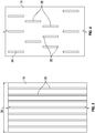
- FIG. 2 provides a schematic of an exemplary belt construction or design.
- Each belt 16 is constructed of a plurality of tension members, for example, cords 24 in a jacket 26.
- the cords 24 of the belt 16 could all be identical, or some or all of the cords 24 used in the belt 16 could be different than the other cords 24.
- the cords 24 are the primary load-carrying members of the belt 16.
- one or more of the cords 24 could have a different construction or size than the other cords 24.
- the cords 24 may be formed from a plurality of wires 28, which in some embodiments are arranged into a plurality of strands 30.
- the belt 16 has an aspect ratio greater than one (i.e. belt width is greater than belt thickness).
- the belt 16 is constructed to have sufficient flexibility when passing over the one or more sheaves 18 to provide low bending stresses, meet belt life requirements and have smooth operation, while being sufficiently strong to be capable of meeting strength requirements for suspending and/or driving the elevator car 12.
- the jacket 26 could be any suitable material, including a single material, multiple materials, two or more layers using the same or dissimilar materials, and/or a film.
- the jacket 26 could be a polymer, such as an elastomer, applied to the cords 24 using, for example, an extrusion or a mold wheel process.
- the jacket 26 could be a textile that engages and/or integrates the cords 24.
- the jacket 26 could be one or more of the previously mentioned alternatives in combination.
- the jacket 26 can substantially retain the cords 24 therein.
- the phrase substantially retain means that the jacket 26 has sufficient engagement with the cords 24 such that the cords 24 do not pull out of, detach from, and/or cut through the jacket 26 during the application on the belt 16 of a load that can be encountered during use in an elevator system 10 with, potentially, an additional factor of safety.
- the cords 24 remain at their original positions relative to the jacket 26 during use in an elevator system 10.
- the jacket 26 could completely envelop the cords 24 (such as shown in FIG. 2 ), substantially envelop the cords 24, or at least partially envelop the cords 24
- the belt 16 includes at least one traction surface 32 interactive with a sheave outer surface 34.
- the sheave outer surface 34 may be substantially flat along its width as shown, or alternatively may include a crown or other features to improve tracking of the belt 16 over the sheave 18.
- Some belts 16 may have two traction surfaces 32, for use in elevator systems where the sheave 18 dictates that two traction surfaces 32 will interact with sheaves 18, such as the arrangement shown in FIG. 1A .
- the belt 16 includes a plurality of grooves 36 formed in the jacket 26, extending longitudinally along a length of the belt 16 as shown in FIG. 3 .
- the grooves 36 are arrayed along a belt width 38 with, in some embodiments, each groove 36 positioned between adjacent cords 24 of the belt 16.
- Each groove 36 has a groove width 40 and a groove depth 42, and in some embodiments a ratio of groove width 40 to groove depth 42 is greater than 1.
- the groove depth 42 is related to a jacket material depth 44 at each cord 24, at which the jacket material depth is thinnest, and may be between one-tenth and one-half of the jacket material depth 44.
- the grooves 36 may have a smooth, continuous curvilinear shape along their width as shown in FIG. 2 , but other groove 36 shapes, such as U-shaped or V-shaped may also be utilized. Further, the grooves 36 may have substantially identical cross-sections as shown or may be varied depending on their location in the belt 16. In some embodiments, as shown in FIG. 3 , the grooves 36 are continuous along a length of the belt 16, while in other embodiments, such as shown in FIG. 4 , the grooves 36 may be discontinuous or staggered along the length of the belt 16. Further, the grooves 36 may have varying cross-sectional shapes along their length.
- the grooves 36 may be formed in the belt 16 during the mold wheel or extrusion process of jacket 26 application to the cords 24, or alternatively may be formed via a secondary process.
- the belt 16 may be passed through a secondary molding process to form the grooves 36 in the jacket 26 while the jacket 26 is still at an elevated temperature from the initial application process.
- the grooves 36 may be formed in the jacket 26 by, for example, a machining process.
- the grooved traction surface 32 interacts with the continuous sheave outer surface 34 to stabilize traction due to the reduction in surface area of the traction surface 32 in contact with the sheave outer surface 34, compared to a continuous, grooveless traction surface.
- the introduction of grooves 36 also improves flexibility of the belt 16, increasing conformability of the belt 16 to the sheave outer surface 34, especially when the sheave outer surface 34 includes a crown. This property is useful, too when it is required to utilize a comparatively stiff jacket 26 material to satisfy other performance requirements such as durability or service life.
- Y et another advantage provided by inclusion of the grooves 36 in the belt 16 is that the grooves 36 increase resistance of the belt 16 to decreases in performance due to external contaminants, such as dry contaminants. During operation of the elevator system, such materials are shunted to and collected in the grooves 36 away from the contact portians of the traction surface 32 to the sheave outer surface 34.
Landscapes
- Engineering & Computer Science (AREA)
- Automation & Control Theory (AREA)
- Structural Engineering (AREA)
- Lift-Guide Devices, And Elevator Ropes And Cables (AREA)
- Cage And Drive Apparatuses For Elevators (AREA)
Description
- The subject matter disclosed herein relates to elevator systems. More specifically, the subject disclosure relates to configurations of coated steel belts for suspending and/or driving elevator cars of an elevator system.
- Elevator systems utilize ropes or belts operably connected to an elevator car, and routed over one or more sheaves, also known as pulleys, to propel the elevator car along a hoistway. Coated steel belts in particular include a plurality of wires located at least partially within a jacket material. The plurality of wires is often arranged into one or more strands and the strands are then arranged into one or more cords. In an exemplary belt construction, a plurality of cords is typically arranged equally spaced within a jacket in a longitudinal direction. The jacket is typically a polymeric-based material such as rubber or polyurethane.
- The belt interacts with the sheaves in the elevator system, one or more of which is a traction sheave driven by a machine. The system utilizes traction between the belt and the traction sheave, such that when the traction sheave is rotated by the machine, the belt is driven over the traction sheave to raise or lower the elevator car along its path. A critical characteristic of the traction sheave/belt interface is stable and predictable traction of a desired level between the belt and the surface of the traction sheave. Further, the belt should be flexible in order to travel uniformly over crowned sheaves of the elevator system used to enhance tracking of the elevator belt.
-
DE 10 2009 003 796 A1 discloses a mechanism having steel cables coated by a coating consisting of an elastomer material, i.e., polyurethane, to form coated steel cables. A free space is provided passing from a broadside of the mechanism to a center plane fixed in cross-section of mechanism by center of the cables. Ratio between diameter of its coated steel cable and diameter of the steel cable is 1.2-1.6. Its cables are connected with each other by a connector layer with a through hole at which a space is provided passing through entire cross-sectional height of the mechanism. -
DE 10 2009 025 954 A1 discloses a belt having traction supports arranged at a distance from each other in a common plane and running in longitudinal direction of the belt, where the belt is embedded in elastomer material, i.e., polyurethane. A groove runs in longitudinal direction of its belt, and is formed in a projection of the traction supports on a belt surface. Its belt is structured in single traces by the groove, where single trace traction surfaces of the traces are combined to form a surface that is smaller around 5-10% than a traction surface formed by entire width of the belt surface. -
US 2008/0087500 A1 discloses an elevator with belt-sheaves and at least one flat belt to suspend and move an elevator car. For the purpose of guiding the flat belt on the belt-sheaves, its belt has at least one guide groove in which at least one guide rib projecting from the sheave running surface of the belt-sheave engages. -
US 2010/0243378 A1 discloses an elevator with a car, a counterweight, a suspension working together with the car and the counterweight, and a wheel at least partially wound around by the suspension, wherein the suspension comprises a tie beam arrangement made of two tie beams and a shell encasing the tie beam arrangement, its shell having a longitudinal structure in an area of an outer surface partially winding around the wheel, and wherein the ratio of the width of the suspension to the height thereof is greater than one and less than or equal to three. Its wheel comprises a groove for guiding the suspension on the sides, in which the suspension is at least partially received, and the groove floor thereof being formed flat. Its shell is coated, at least in areas, on the outer surface thereof, wherein its coating optionally has a friction-reducing, friction-increasing, and/or wear-reducing effect. - In one embodiment, a belt according to claim 1 is provided.
- Additionally, the groove is positioned laterally between adjacent tension members of the plurality of tension members.
- Additionally, the groove has a ratio of groove width to groove depth of 1 or more.
- Additionally, two or more grooves are arranged in nonidentical lateral positions in the belt outer surface.
- Additionally, the two or more grooves are staggered in position longitudinally along the belt length.
- Additionally, two belt outer surfaces define a belt thickness, each outer belt surface including a groove.
- Additionally, the plurality of tension members include a plurality of wires arranged into a plurality of cords.
- Additionally, the jacket material is one of a rubber or polyurethane material.
- In another embodiment, an elevator system according to claim 9 is provided.
- Additionally, a sheave of the one or more sheaves includes a crowned sheave surface and the groove increases belt conformance to the crowned sheave surface.
-
-
FIG. 1A is a schematic of an exemplary elevator system having a 1:1 roping arrangement; -
FIG. 1B is a schematic of another exemplary elevator system having a different roping arrangement; -
FIG. 1C is a schematic of another exemplary elevator system having a cantilevered arrangement; -
FIG. 2 is a cross-sectional view of a non-claimed embodiment of a belt for an elevator system; -
FIG. 3 is a plan view of a non-claimed embodiment of a belt for an elevator system; and -
FIG. 4 is a plan view of another embodiment of a belt for an elevator system. - The detailed description explains the invention, together with advantages and features, by way of examples with reference to the drawings.
- Shown in
FIGS. 1A ,1B and1C are schematics of exemplarytraction elevator systems 10. Features of theelevator system 10 that are not required for an understanding of the present invention (such as the guide rails, safeties, etc.) are not discussed herein. Theelevator system 10 includes anelevator car 12 operatively suspended or supported in ahoistway 14 with one ormore belts 16. The one ormore belts 16 interact with one ormore sheaves 18 to be routed around various components of theelevator system 10. The one ormore belts 16 could also be connected to acounterweight 22, which is used to help balance theelevator system 10 and reduce the difference in belt tension on both sides of the traction sheave during operation. - The
sheaves 18 each have adiameter 20, which may be the same or different than the diameters of theother sheaves 18 in theelevator system 10. At least one of thesheaves 18 could be a drive sheave. A drive sheave is driven by amachine 50. Movement of drive sheave by themachine 50 drives, moves and/or propels (through traction) the one ormore belts 16 that are routed around the drive sheave. - At least one of the
sheaves 18 could be a diverter, deflector or idler sheave. Diverter, deflector or idler sheaves are not driven by amachine 50, but help guide the one ormore belts 16 around the various components of theelevator system 10. - In some embodiments, the
elevator system 10 could use two ormore belts 16 for suspending and/or driving theelevator car 12. In addition, theelevator system 10 could have various configurations such that either both sides of the one ormore belts 16 engage the one or more sheaves 18 (such as shown in the exemplary elevator systems inFIGS. 1A ,1B or1C ) or only one side of the one ormore belts 16 engages the one ormore sheaves 18. -
FIG 1A provides a 1:1 roping arrangement in which the one ormore belts 16 terminate at thecar 12 andcounterweight 22.FIGS. 1B and1C provide different roping arrangements. Specifically,FIGS. 1B and1C show that thecar 12 and/or thecounterweight 22 can have one ormore sheaves 18 thereon engaging the one ormore belts 16 and the one ormore belts 16 can terminate elsewhere, typically at a structure within the hoistway 14 (such as for a machine room-less elevator system) or within the machine room (for elevator systems utilizing a machine room. The number ofsheaves 18 used in the arrangement determines the specific roping ratio (e.g. the 2:1 roping ratio shown inFIGS. 1B and1C or a different ratio).FIG 1C also provides a so-called rucksack or cantilevered type elevator. The present invention could be used on elevator systems other than the exemplary types shown inFIGS. 1A ,1B and1C . -
FIG. 2 provides a schematic of an exemplary belt construction or design. Eachbelt 16 is constructed of a plurality of tension members, for example,cords 24 in ajacket 26. Thecords 24 of thebelt 16 could all be identical, or some or all of thecords 24 used in thebelt 16 could be different than theother cords 24. Thecords 24 are the primary load-carrying members of thebelt 16. For example, one or more of thecords 24 could have a different construction or size than theother cords 24. Thecords 24 may be formed from a plurality ofwires 28, which in some embodiments are arranged into a plurality ofstrands 30. As seen inFIG. 2 , thebelt 16 has an aspect ratio greater than one (i.e. belt width is greater than belt thickness). - The
belt 16 is constructed to have sufficient flexibility when passing over the one ormore sheaves 18 to provide low bending stresses, meet belt life requirements and have smooth operation, while being sufficiently strong to be capable of meeting strength requirements for suspending and/or driving theelevator car 12. - The
jacket 26 could be any suitable material, including a single material, multiple materials, two or more layers using the same or dissimilar materials, and/or a film. In one arrangement, thejacket 26 could be a polymer, such as an elastomer, applied to thecords 24 using, for example, an extrusion or a mold wheel process. In another arrangement, thejacket 26 could be a textile that engages and/or integrates thecords 24. As an additional arrangement, thejacket 26 could be one or more of the previously mentioned alternatives in combination. - The
jacket 26 can substantially retain thecords 24 therein. The phrase substantially retain means that thejacket 26 has sufficient engagement with thecords 24 such that thecords 24 do not pull out of, detach from, and/or cut through thejacket 26 during the application on thebelt 16 of a load that can be encountered during use in anelevator system 10 with, potentially, an additional factor of safety. In other words, thecords 24 remain at their original positions relative to thejacket 26 during use in anelevator system 10. Thejacket 26 could completely envelop the cords 24 (such as shown inFIG. 2 ), substantially envelop thecords 24, or at least partially envelop thecords 24 - The
belt 16 includes at least onetraction surface 32 interactive with a sheaveouter surface 34. The sheaveouter surface 34 may be substantially flat along its width as shown, or alternatively may include a crown or other features to improve tracking of thebelt 16 over thesheave 18. Somebelts 16 may have two traction surfaces 32, for use in elevator systems where thesheave 18 dictates that two traction surfaces 32 will interact withsheaves 18, such as the arrangement shown inFIG. 1A . - The
belt 16 includes a plurality ofgrooves 36 formed in thejacket 26, extending longitudinally along a length of thebelt 16 as shown inFIG. 3 . Referring again to the cross-section ofFIG. 2 , thegrooves 36 are arrayed along abelt width 38 with, in some embodiments, eachgroove 36 positioned betweenadjacent cords 24 of thebelt 16. Eachgroove 36 has agroove width 40 and agroove depth 42, and in some embodiments a ratio ofgroove width 40 to groovedepth 42 is greater than 1. In some embodiments, thegroove depth 42 is related to ajacket material depth 44 at eachcord 24, at which the jacket material depth is thinnest, and may be between one-tenth and one-half of thejacket material depth 44. Thegrooves 36 may have a smooth, continuous curvilinear shape along their width as shown inFIG. 2 , butother groove 36 shapes, such as U-shaped or V-shaped may also be utilized. Further, thegrooves 36 may have substantially identical cross-sections as shown or may be varied depending on their location in thebelt 16. In some embodiments, as shown inFIG. 3 , thegrooves 36 are continuous along a length of thebelt 16, while in other embodiments, such as shown inFIG. 4 , thegrooves 36 may be discontinuous or staggered along the length of thebelt 16. Further, thegrooves 36 may have varying cross-sectional shapes along their length. - The
grooves 36 may be formed in thebelt 16 during the mold wheel or extrusion process ofjacket 26 application to thecords 24, or alternatively may be formed via a secondary process. For example, thebelt 16 may be passed through a secondary molding process to form thegrooves 36 in thejacket 26 while thejacket 26 is still at an elevated temperature from the initial application process. Alternatively, after forming of thejacket 26 on thebelt 16 in completed, thegrooves 36 may be formed in thejacket 26 by, for example, a machining process. - The grooved
traction surface 32 interacts with the continuous sheaveouter surface 34 to stabilize traction due to the reduction in surface area of thetraction surface 32 in contact with the sheaveouter surface 34, compared to a continuous, grooveless traction surface. The introduction ofgrooves 36 also improves flexibility of thebelt 16, increasing conformability of thebelt 16 to the sheaveouter surface 34, especially when the sheaveouter surface 34 includes a crown. This property is useful, too when it is required to utilize a comparativelystiff jacket 26 material to satisfy other performance requirements such as durability or service life. Y et another advantage provided by inclusion of thegrooves 36 in thebelt 16 is that thegrooves 36 increase resistance of thebelt 16 to decreases in performance due to external contaminants, such as dry contaminants. During operation of the elevator system, such materials are shunted to and collected in thegrooves 36 away from the contact portians of thetraction surface 32 to the sheaveouter surface 34. - While the invention has been described in detail in connection with only a limited number of embodiments, it should be readily understood that the invention is not limited to such disclosed embodiments. Rather, the invention can be modified to incorporate any number of variations, alterations, Substitutions or equivalent arrangements not heretofore described, but which are commensurate with the scope of the claims. Additionally, while various embodiments of the invention have been described, it is to be understood that aspects of the invention may include only some of the described embodiments. Accordingly, the invention is not to be seen as limited by the foregoing description, but is only limited by the scope of the appended claims.
Claims (10)
- A belt (16) for suspending and/or driving an elevator car (12) of an elevator system (10) comprising:a plurality of tension members (30) spaced from each other along a width (38) of the belt (16) and extending longitudinally along a length of the belt (16);a jacket (26) at least partially enveloping the plurality of tension members (30) and forming at least one outer belt surface (32) along the width (38) of the belt (16);a groove (36) located in the at least one outer belt surface (32) extending longitudinally along the length of the belt (16),characterized in thatthe groove (36) has a groove depth (42) between one tenth and one half of a jacket material depth (44) at the tension member (30) andthe groove (36) is discontinuous along a length of the belt (16).
- The belt (16) of claim 1, wherein the groove (36) is disposed laterally between adjacent tension members (30) of the plurality of tension members (30).
- The belt (16) of any of claims 1-2, wherein the groove (36) has a ratio of groove width (40) to groove depth (42) of 1 or more.
- The belt (16) of any of claims 1-3, further comprising two or more grooves (36) arranged in nonidentical lateral positions in the belt outer surface (32).
- The belt (16) of claim 4, wherein the two or more grooves (36) are staggered in position longitudinally along the belt length.
- The belt (16) of any of claims 1-5, further comprising two belt outer surfaces (32) defining a belt thickness, each outer belt surface (32) including a groove (36).
- The belt (16) of any of claims 1-6, wherein the plurality of tension members (30) comprise a plurality of wires (28) arranged into a plurality of cords (24).
- The belt (16) of any of claims 1-7, wherein the jacket material is one of a rubber or polyurethane material.
- An elevator system (10) comprising:an elevator car (12);one or more sheaves (18); andone or more belts (16) according to any of the previous claims, the one or more belts (16) operably connected to the car (12) and interactive with the one or more sheaves (18) for suspending and/or driving the elevator car (12),the jacket (26) forming at least one outer belt surface (32) along a width (38) of the belt (16), the outer belt surface (32) interactive with the one or more sheaves (18).
- The elevator system of claim 9, wherein a sheave (18) of the one or more sheaves (18) includes a crowned sheave surface (34) and the groove (36) increases belt conformance to the crowned sheave surface (34). .
Applications Claiming Priority (1)
| Application Number | Priority Date | Filing Date | Title |
|---|---|---|---|
| PCT/US2014/032524 WO2015152899A1 (en) | 2014-04-01 | 2014-04-01 | Grooved belt for elevator system |
Publications (3)
| Publication Number | Publication Date |
|---|---|
| EP3126277A1 EP3126277A1 (en) | 2017-02-08 |
| EP3126277A4 EP3126277A4 (en) | 2017-11-01 |
| EP3126277B1 true EP3126277B1 (en) | 2020-08-12 |
Family
ID=54241028
Family Applications (1)
| Application Number | Title | Priority Date | Filing Date |
|---|---|---|---|
| EP14888104.8A Active EP3126277B1 (en) | 2014-04-01 | 2014-04-01 | Grooved belt for elevator system |
Country Status (4)
| Country | Link |
|---|---|
| US (1) | US10926975B2 (en) |
| EP (1) | EP3126277B1 (en) |
| CN (2) | CN106163961A (en) |
| WO (1) | WO2015152899A1 (en) |
Families Citing this family (4)
| Publication number | Priority date | Publication date | Assignee | Title |
|---|---|---|---|---|
| KR102435427B1 (en) | 2016-03-15 | 2022-08-24 | 오티스 엘리베이터 컴파니 | Load-bearing members with transverse layers |
| US10894696B2 (en) | 2016-07-11 | 2021-01-19 | Otis Elevator Company | Belt with guide elements |
| US10926976B2 (en) * | 2018-06-18 | 2021-02-23 | Otis Elevator Company | Belt with corrugated material |
| DE102019212671A1 (en) * | 2019-08-23 | 2021-02-25 | Contitech Antriebssysteme Gmbh | Pull or shoulder strap |
Family Cites Families (17)
| Publication number | Priority date | Publication date | Assignee | Title |
|---|---|---|---|---|
| US3948113A (en) * | 1974-11-29 | 1976-04-06 | The Goodyear Tire & Rubber Company | Multi-ribbed power transmission belt and method of making said belt |
| US5704862A (en) | 1997-01-13 | 1998-01-06 | The Goodyear Tire & Rubber Company | Dual sided poly-V drive belt and pulley therefor |
| US6056656A (en) * | 1997-03-04 | 2000-05-02 | Bando Chemical Industries, Ltd. | V-ribbed belt |
| EP1561719B1 (en) * | 2002-11-12 | 2012-01-25 | Mitsubishi Denki Kabushiki Kaisha | Rope for elevator and elevator equipment |
| ATE325771T1 (en) | 2004-01-06 | 2006-06-15 | Inventio Ag | ELEVATOR SYSTEM |
| MY143607A (en) * | 2004-10-18 | 2011-06-15 | Inventio Ag | Lift comprising a flat-belt as a tractive element |
| TW200710013A (en) * | 2005-07-25 | 2007-03-16 | Inventio Ag | Installation with support means for driving a lift cage, and corresponding support means |
| WO2009050182A2 (en) * | 2007-10-17 | 2009-04-23 | Inventio Ag | Elevator having a suspension |
| US9050768B2 (en) * | 2008-04-14 | 2015-06-09 | Inventio Ag | Method and device for producing a support belt for an elevator installation |
| DE102008037536A1 (en) * | 2008-11-10 | 2010-05-12 | Contitech Antriebssysteme Gmbh | Traction means, traction drive with this traction device and elevator system |
| JP5600683B2 (en) | 2008-11-14 | 2014-10-01 | オーチス エレベータ カンパニー | Elevator belt forming method |
| DE102009003796A1 (en) * | 2009-04-17 | 2010-10-21 | Contitech Antriebssysteme Gmbh | Traction mechanism for use in traction mechanism drive for lift facility, has connector layer including through hole at which free space is passed through entire cross-sectional height of traction mechanism |
| DE102009025954A1 (en) * | 2009-06-10 | 2010-12-16 | Contitech Antriebssysteme Gmbh | Flat belt for flat belt drive of lift, has traction supports arranged at distance from each other, where traction surfaces of traces are combined to form surface that is smaller than traction surface formed by entire width of belt surface |
| EP2558398A2 (en) * | 2010-04-12 | 2013-02-20 | Inventio AG | Supporting means for an elevator system |
| CN202072377U (en) * | 2011-05-09 | 2011-12-14 | 黄立成 | Elevator traction component and asynchronous gearless driving device applied to same |
| US10023433B2 (en) * | 2012-10-22 | 2018-07-17 | Inventio Ag | Monitoring of support in elevator installations |
| ES2609467T3 (en) * | 2013-10-10 | 2017-04-20 | Kone Corporation | Cable for a lifting and lifting device |
-
2014
- 2014-04-01 US US15/301,442 patent/US10926975B2/en active Active
- 2014-04-01 EP EP14888104.8A patent/EP3126277B1/en active Active
- 2014-04-01 CN CN201480077809.2A patent/CN106163961A/en active Pending
- 2014-04-01 CN CN202011368029.7A patent/CN112551308B/en active Active
- 2014-04-01 WO PCT/US2014/032524 patent/WO2015152899A1/en not_active Ceased
Non-Patent Citations (1)
| Title |
|---|
| None * |
Also Published As
| Publication number | Publication date |
|---|---|
| CN106163961A (en) | 2016-11-23 |
| US20170022029A1 (en) | 2017-01-26 |
| WO2015152899A1 (en) | 2015-10-08 |
| EP3126277A4 (en) | 2017-11-01 |
| EP3126277A1 (en) | 2017-02-08 |
| CN112551308B (en) | 2022-08-02 |
| US10926975B2 (en) | 2021-02-23 |
| CN112551308A (en) | 2021-03-26 |
Similar Documents
| Publication | Publication Date | Title |
|---|---|---|
| EP3071504B1 (en) | Idler or deflector sheave for elevator system | |
| KR102558426B1 (en) | Tension member for elevator system belt | |
| CN106115436B (en) | Refractory coated steel strip | |
| EP3205616B1 (en) | Surface construction of elevator belt | |
| EP3126277B1 (en) | Grooved belt for elevator system | |
| EP3336034B1 (en) | Elevator system suspension member | |
| US10301151B2 (en) | Traction sheave for elevator system | |
| US10221043B2 (en) | Elevator suspension and/or driving arrangement | |
| US20180179023A1 (en) | Increased traction of elevator system belt | |
| EP2909372B1 (en) | Method of elevator cord cleaning and heating | |
| HK1188427A (en) | Elevator suspension and/or driving arrangement | |
| HK1188426A (en) | Elevator system belt | |
| HK1188426B (en) | Elevator system belt | |
| HK1181024B (en) | Elevator suspension and/or driving assembly having at least one traction surface defined by weave fibers |
Legal Events
| Date | Code | Title | Description |
|---|---|---|---|
| STAA | Information on the status of an ep patent application or granted ep patent |
Free format text: STATUS: THE INTERNATIONAL PUBLICATION HAS BEEN MADE |
|
| PUAI | Public reference made under article 153(3) epc to a published international application that has entered the european phase |
Free format text: ORIGINAL CODE: 0009012 |
|
| STAA | Information on the status of an ep patent application or granted ep patent |
Free format text: STATUS: REQUEST FOR EXAMINATION WAS MADE |
|
| 17P | Request for examination filed |
Effective date: 20161027 |
|
| AK | Designated contracting states |
Kind code of ref document: A1 Designated state(s): AL AT BE BG CH CY CZ DE DK EE ES FI FR GB GR HR HU IE IS IT LI LT LU LV MC MK MT NL NO PL PT RO RS SE SI SK SM TR |
|
| AX | Request for extension of the european patent |
Extension state: BA ME |
|
| DAX | Request for extension of the european patent (deleted) | ||
| RAP1 | Party data changed (applicant data changed or rights of an application transferred) |
Owner name: OTIS ELEVATOR COMPANY |
|
| A4 | Supplementary search report drawn up and despatched |
Effective date: 20171002 |
|
| RIC1 | Information provided on ipc code assigned before grant |
Ipc: B66B 7/06 20060101AFI20170926BHEP |
|
| STAA | Information on the status of an ep patent application or granted ep patent |
Free format text: STATUS: EXAMINATION IS IN PROGRESS |
|
| 17Q | First examination report despatched |
Effective date: 20190830 |
|
| GRAP | Despatch of communication of intention to grant a patent |
Free format text: ORIGINAL CODE: EPIDOSNIGR1 |
|
| STAA | Information on the status of an ep patent application or granted ep patent |
Free format text: STATUS: GRANT OF PATENT IS INTENDED |
|
| INTG | Intention to grant announced |
Effective date: 20200305 |
|
| GRAS | Grant fee paid |
Free format text: ORIGINAL CODE: EPIDOSNIGR3 |
|
| GRAA | (expected) grant |
Free format text: ORIGINAL CODE: 0009210 |
|
| STAA | Information on the status of an ep patent application or granted ep patent |
Free format text: STATUS: THE PATENT HAS BEEN GRANTED |
|
| AK | Designated contracting states |
Kind code of ref document: B1 Designated state(s): AL AT BE BG CH CY CZ DE DK EE ES FI FR GB GR HR HU IE IS IT LI LT LU LV MC MK MT NL NO PL PT RO RS SE SI SK SM TR |
|
| REG | Reference to a national code |
Ref country code: CH Ref legal event code: EP |
|
| REG | Reference to a national code |
Ref country code: IE Ref legal event code: FG4D |
|
| REG | Reference to a national code |
Ref country code: DE Ref legal event code: R096 Ref document number: 602014069011 Country of ref document: DE |
|
| REG | Reference to a national code |
Ref country code: AT Ref legal event code: REF Ref document number: 1301380 Country of ref document: AT Kind code of ref document: T Effective date: 20200915 |
|
| REG | Reference to a national code |
Ref country code: LT Ref legal event code: MG4D |
|
| REG | Reference to a national code |
Ref country code: NL Ref legal event code: MP Effective date: 20200812 |
|
| PG25 | Lapsed in a contracting state [announced via postgrant information from national office to epo] |
Ref country code: FI Free format text: LAPSE BECAUSE OF FAILURE TO SUBMIT A TRANSLATION OF THE DESCRIPTION OR TO PAY THE FEE WITHIN THE PRESCRIBED TIME-LIMIT Effective date: 20200812 Ref country code: GR Free format text: LAPSE BECAUSE OF FAILURE TO SUBMIT A TRANSLATION OF THE DESCRIPTION OR TO PAY THE FEE WITHIN THE PRESCRIBED TIME-LIMIT Effective date: 20201113 Ref country code: NO Free format text: LAPSE BECAUSE OF FAILURE TO SUBMIT A TRANSLATION OF THE DESCRIPTION OR TO PAY THE FEE WITHIN THE PRESCRIBED TIME-LIMIT Effective date: 20201112 Ref country code: SE Free format text: LAPSE BECAUSE OF FAILURE TO SUBMIT A TRANSLATION OF THE DESCRIPTION OR TO PAY THE FEE WITHIN THE PRESCRIBED TIME-LIMIT Effective date: 20200812 Ref country code: BG Free format text: LAPSE BECAUSE OF FAILURE TO SUBMIT A TRANSLATION OF THE DESCRIPTION OR TO PAY THE FEE WITHIN THE PRESCRIBED TIME-LIMIT Effective date: 20201112 Ref country code: LT Free format text: LAPSE BECAUSE OF FAILURE TO SUBMIT A TRANSLATION OF THE DESCRIPTION OR TO PAY THE FEE WITHIN THE PRESCRIBED TIME-LIMIT Effective date: 20200812 Ref country code: HR Free format text: LAPSE BECAUSE OF FAILURE TO SUBMIT A TRANSLATION OF THE DESCRIPTION OR TO PAY THE FEE WITHIN THE PRESCRIBED TIME-LIMIT Effective date: 20200812 |
|
| REG | Reference to a national code |
Ref country code: AT Ref legal event code: MK05 Ref document number: 1301380 Country of ref document: AT Kind code of ref document: T Effective date: 20200812 |
|
| PG25 | Lapsed in a contracting state [announced via postgrant information from national office to epo] |
Ref country code: PL Free format text: LAPSE BECAUSE OF FAILURE TO SUBMIT A TRANSLATION OF THE DESCRIPTION OR TO PAY THE FEE WITHIN THE PRESCRIBED TIME-LIMIT Effective date: 20200812 Ref country code: LV Free format text: LAPSE BECAUSE OF FAILURE TO SUBMIT A TRANSLATION OF THE DESCRIPTION OR TO PAY THE FEE WITHIN THE PRESCRIBED TIME-LIMIT Effective date: 20200812 Ref country code: NL Free format text: LAPSE BECAUSE OF FAILURE TO SUBMIT A TRANSLATION OF THE DESCRIPTION OR TO PAY THE FEE WITHIN THE PRESCRIBED TIME-LIMIT Effective date: 20200812 Ref country code: RS Free format text: LAPSE BECAUSE OF FAILURE TO SUBMIT A TRANSLATION OF THE DESCRIPTION OR TO PAY THE FEE WITHIN THE PRESCRIBED TIME-LIMIT Effective date: 20200812 Ref country code: IS Free format text: LAPSE BECAUSE OF FAILURE TO SUBMIT A TRANSLATION OF THE DESCRIPTION OR TO PAY THE FEE WITHIN THE PRESCRIBED TIME-LIMIT Effective date: 20201212 |
|
| PG25 | Lapsed in a contracting state [announced via postgrant information from national office to epo] |
Ref country code: DK Free format text: LAPSE BECAUSE OF FAILURE TO SUBMIT A TRANSLATION OF THE DESCRIPTION OR TO PAY THE FEE WITHIN THE PRESCRIBED TIME-LIMIT Effective date: 20200812 Ref country code: CZ Free format text: LAPSE BECAUSE OF FAILURE TO SUBMIT A TRANSLATION OF THE DESCRIPTION OR TO PAY THE FEE WITHIN THE PRESCRIBED TIME-LIMIT Effective date: 20200812 Ref country code: EE Free format text: LAPSE BECAUSE OF FAILURE TO SUBMIT A TRANSLATION OF THE DESCRIPTION OR TO PAY THE FEE WITHIN THE PRESCRIBED TIME-LIMIT Effective date: 20200812 Ref country code: RO Free format text: LAPSE BECAUSE OF FAILURE TO SUBMIT A TRANSLATION OF THE DESCRIPTION OR TO PAY THE FEE WITHIN THE PRESCRIBED TIME-LIMIT Effective date: 20200812 Ref country code: SM Free format text: LAPSE BECAUSE OF FAILURE TO SUBMIT A TRANSLATION OF THE DESCRIPTION OR TO PAY THE FEE WITHIN THE PRESCRIBED TIME-LIMIT Effective date: 20200812 |
|
| REG | Reference to a national code |
Ref country code: DE Ref legal event code: R097 Ref document number: 602014069011 Country of ref document: DE |
|
| PG25 | Lapsed in a contracting state [announced via postgrant information from national office to epo] |
Ref country code: ES Free format text: LAPSE BECAUSE OF FAILURE TO SUBMIT A TRANSLATION OF THE DESCRIPTION OR TO PAY THE FEE WITHIN THE PRESCRIBED TIME-LIMIT Effective date: 20200812 Ref country code: AL Free format text: LAPSE BECAUSE OF FAILURE TO SUBMIT A TRANSLATION OF THE DESCRIPTION OR TO PAY THE FEE WITHIN THE PRESCRIBED TIME-LIMIT Effective date: 20200812 Ref country code: AT Free format text: LAPSE BECAUSE OF FAILURE TO SUBMIT A TRANSLATION OF THE DESCRIPTION OR TO PAY THE FEE WITHIN THE PRESCRIBED TIME-LIMIT Effective date: 20200812 |
|
| PLBE | No opposition filed within time limit |
Free format text: ORIGINAL CODE: 0009261 |
|
| STAA | Information on the status of an ep patent application or granted ep patent |
Free format text: STATUS: NO OPPOSITION FILED WITHIN TIME LIMIT |
|
| PG25 | Lapsed in a contracting state [announced via postgrant information from national office to epo] |
Ref country code: SK Free format text: LAPSE BECAUSE OF FAILURE TO SUBMIT A TRANSLATION OF THE DESCRIPTION OR TO PAY THE FEE WITHIN THE PRESCRIBED TIME-LIMIT Effective date: 20200812 |
|
| 26N | No opposition filed |
Effective date: 20210514 |
|
| PG25 | Lapsed in a contracting state [announced via postgrant information from national office to epo] |
Ref country code: IT Free format text: LAPSE BECAUSE OF FAILURE TO SUBMIT A TRANSLATION OF THE DESCRIPTION OR TO PAY THE FEE WITHIN THE PRESCRIBED TIME-LIMIT Effective date: 20200812 |
|
| PG25 | Lapsed in a contracting state [announced via postgrant information from national office to epo] |
Ref country code: SI Free format text: LAPSE BECAUSE OF FAILURE TO SUBMIT A TRANSLATION OF THE DESCRIPTION OR TO PAY THE FEE WITHIN THE PRESCRIBED TIME-LIMIT Effective date: 20200812 |
|
| PG25 | Lapsed in a contracting state [announced via postgrant information from national office to epo] |
Ref country code: MC Free format text: LAPSE BECAUSE OF FAILURE TO SUBMIT A TRANSLATION OF THE DESCRIPTION OR TO PAY THE FEE WITHIN THE PRESCRIBED TIME-LIMIT Effective date: 20200812 |
|
| GBPC | Gb: european patent ceased through non-payment of renewal fee |
Effective date: 20210401 |
|
| PG25 | Lapsed in a contracting state [announced via postgrant information from national office to epo] |
Ref country code: LU Free format text: LAPSE BECAUSE OF NON-PAYMENT OF DUE FEES Effective date: 20210401 |
|
| REG | Reference to a national code |
Ref country code: BE Ref legal event code: MM Effective date: 20210430 |
|
| PG25 | Lapsed in a contracting state [announced via postgrant information from national office to epo] |
Ref country code: GB Free format text: LAPSE BECAUSE OF NON-PAYMENT OF DUE FEES Effective date: 20210401 Ref country code: CH Free format text: LAPSE BECAUSE OF NON-PAYMENT OF DUE FEES Effective date: 20210430 Ref country code: LI Free format text: LAPSE BECAUSE OF NON-PAYMENT OF DUE FEES Effective date: 20210430 |
|
| PG25 | Lapsed in a contracting state [announced via postgrant information from national office to epo] |
Ref country code: IE Free format text: LAPSE BECAUSE OF NON-PAYMENT OF DUE FEES Effective date: 20210401 |
|
| PG25 | Lapsed in a contracting state [announced via postgrant information from national office to epo] |
Ref country code: IS Free format text: LAPSE BECAUSE OF FAILURE TO SUBMIT A TRANSLATION OF THE DESCRIPTION OR TO PAY THE FEE WITHIN THE PRESCRIBED TIME-LIMIT Effective date: 20201212 |
|
| PG25 | Lapsed in a contracting state [announced via postgrant information from national office to epo] |
Ref country code: BE Free format text: LAPSE BECAUSE OF NON-PAYMENT OF DUE FEES Effective date: 20210430 |
|
| PG25 | Lapsed in a contracting state [announced via postgrant information from national office to epo] |
Ref country code: PT Free format text: LAPSE BECAUSE OF FAILURE TO SUBMIT A TRANSLATION OF THE DESCRIPTION OR TO PAY THE FEE WITHIN THE PRESCRIBED TIME-LIMIT Effective date: 20201214 |
|
| PG25 | Lapsed in a contracting state [announced via postgrant information from national office to epo] |
Ref country code: HU Free format text: LAPSE BECAUSE OF FAILURE TO SUBMIT A TRANSLATION OF THE DESCRIPTION OR TO PAY THE FEE WITHIN THE PRESCRIBED TIME-LIMIT; INVALID AB INITIO Effective date: 20140401 |
|
| PG25 | Lapsed in a contracting state [announced via postgrant information from national office to epo] |
Ref country code: CY Free format text: LAPSE BECAUSE OF FAILURE TO SUBMIT A TRANSLATION OF THE DESCRIPTION OR TO PAY THE FEE WITHIN THE PRESCRIBED TIME-LIMIT Effective date: 20200812 |
|
| PG25 | Lapsed in a contracting state [announced via postgrant information from national office to epo] |
Ref country code: MK Free format text: LAPSE BECAUSE OF FAILURE TO SUBMIT A TRANSLATION OF THE DESCRIPTION OR TO PAY THE FEE WITHIN THE PRESCRIBED TIME-LIMIT Effective date: 20200812 |
|
| PG25 | Lapsed in a contracting state [announced via postgrant information from national office to epo] |
Ref country code: MT Free format text: LAPSE BECAUSE OF FAILURE TO SUBMIT A TRANSLATION OF THE DESCRIPTION OR TO PAY THE FEE WITHIN THE PRESCRIBED TIME-LIMIT Effective date: 20200812 |
|
| PGFP | Annual fee paid to national office [announced via postgrant information from national office to epo] |
Ref country code: DE Payment date: 20250319 Year of fee payment: 12 |
|
| PG25 | Lapsed in a contracting state [announced via postgrant information from national office to epo] |
Ref country code: TR Free format text: LAPSE BECAUSE OF FAILURE TO SUBMIT A TRANSLATION OF THE DESCRIPTION OR TO PAY THE FEE WITHIN THE PRESCRIBED TIME-LIMIT Effective date: 20200812 |
|
| PGFP | Annual fee paid to national office [announced via postgrant information from national office to epo] |
Ref country code: FR Payment date: 20260320 Year of fee payment: 13 |