EP3125710B1 - Cartouche de cigarette électronique jetable, et procédé de fabrication correspondant - Google Patents
Cartouche de cigarette électronique jetable, et procédé de fabrication correspondant Download PDFInfo
- Publication number
- EP3125710B1 EP3125710B1 EP15721845.4A EP15721845A EP3125710B1 EP 3125710 B1 EP3125710 B1 EP 3125710B1 EP 15721845 A EP15721845 A EP 15721845A EP 3125710 B1 EP3125710 B1 EP 3125710B1
- Authority
- EP
- European Patent Office
- Prior art keywords
- hygroscopic pad
- disposable cartridge
- liquid substance
- hygroscopic
- pad
- Prior art date
- Legal status (The legal status is an assumption and is not a legal conclusion. Google has not performed a legal analysis and makes no representation as to the accuracy of the status listed.)
- Not-in-force
Links
Images

Classifications
-
- A—HUMAN NECESSITIES
- A24—TOBACCO; CIGARS; CIGARETTES; SIMULATED SMOKING DEVICES; SMOKERS' REQUISITES
- A24F—SMOKERS' REQUISITES; MATCH BOXES; SIMULATED SMOKING DEVICES
- A24F40/00—Electrically operated smoking devices; Component parts thereof; Manufacture thereof; Maintenance or testing thereof; Charging means specially adapted therefor
- A24F40/50—Control or monitoring
- A24F40/51—Arrangement of sensors
-
- A—HUMAN NECESSITIES
- A24—TOBACCO; CIGARS; CIGARETTES; SIMULATED SMOKING DEVICES; SMOKERS' REQUISITES
- A24F—SMOKERS' REQUISITES; MATCH BOXES; SIMULATED SMOKING DEVICES
- A24F40/00—Electrically operated smoking devices; Component parts thereof; Manufacture thereof; Maintenance or testing thereof; Charging means specially adapted therefor
- A24F40/40—Constructional details, e.g. connection of cartridges and battery parts
- A24F40/42—Cartridges or containers for inhalable precursors
-
- A—HUMAN NECESSITIES
- A24—TOBACCO; CIGARS; CIGARETTES; SIMULATED SMOKING DEVICES; SMOKERS' REQUISITES
- A24F—SMOKERS' REQUISITES; MATCH BOXES; SIMULATED SMOKING DEVICES
- A24F40/00—Electrically operated smoking devices; Component parts thereof; Manufacture thereof; Maintenance or testing thereof; Charging means specially adapted therefor
- A24F40/70—Manufacture
-
- H—ELECTRICITY
- H05—ELECTRIC TECHNIQUES NOT OTHERWISE PROVIDED FOR
- H05B—ELECTRIC HEATING; ELECTRIC LIGHT SOURCES NOT OTHERWISE PROVIDED FOR; CIRCUIT ARRANGEMENTS FOR ELECTRIC LIGHT SOURCES, IN GENERAL
- H05B1/00—Details of electric heating devices
- H05B1/02—Automatic switching arrangements specially adapted to apparatus ; Control of heating devices
- H05B1/0227—Applications
- H05B1/023—Industrial applications
- H05B1/0244—Heating of fluids
-
- A—HUMAN NECESSITIES
- A24—TOBACCO; CIGARS; CIGARETTES; SIMULATED SMOKING DEVICES; SMOKERS' REQUISITES
- A24F—SMOKERS' REQUISITES; MATCH BOXES; SIMULATED SMOKING DEVICES
- A24F40/00—Electrically operated smoking devices; Component parts thereof; Manufacture thereof; Maintenance or testing thereof; Charging means specially adapted therefor
- A24F40/10—Devices using liquid inhalable precursors
-
- H—ELECTRICITY
- H05—ELECTRIC TECHNIQUES NOT OTHERWISE PROVIDED FOR
- H05B—ELECTRIC HEATING; ELECTRIC LIGHT SOURCES NOT OTHERWISE PROVIDED FOR; CIRCUIT ARRANGEMENTS FOR ELECTRIC LIGHT SOURCES, IN GENERAL
- H05B2203/00—Aspects relating to Ohmic resistive heating covered by group H05B3/00
- H05B2203/021—Heaters specially adapted for heating liquids
Definitions
- the present invention relates to a disposable electronic-cigarette cartridge and to a respective production method.
- a known disposable cartridge (for example as disclosed in Patent Application EP2489391A1 ) comprises a rigid container (generally of a cylindrical shape), inside which a hygroscopic pad is housed (such as a cotton pad) that has been previously impregnated with the viscous liquid substance containing nicotine and possible flavourings; a resistor is also provided, which is thermally coupled to the hygroscopic pad (for example, the electric resistor is constituted by a wire wound around the hygroscopic pad) and in use electrical current flows through it so as to heat the hygroscopic pad and therefore cause the slow volatilization (vapourization) of the viscous liquid substance which impregnates the hygroscopic pad.
- the rigid container has openings (typically on one of the two circular bases) through which the vapours generated by the volatilization (vapourization) of the liquid substance flow out from the rigid container to be inhaled by the smoker.
- the production of said disposable cartridges entails producing the rigid container with an open top end, inserting the dry hygroscopic pad inside the rigid containers, filling the rigid container with a calibrated amount of the liquid substance, and then capping the rigid containers by applying to the open top end a cap permeable to vapours (i.e. a cap that prevents the liquid substance from leaking, but that does not prevent the vapour, generated by heating the liquid substance, from escaping); once the cap is applied, a corresponding adhesive label is wrapped around each cartridge to terminate the production process.
- a cap permeable to vapours i.e. a cap that prevents the liquid substance from leaking, but that does not prevent the vapour, generated by heating the liquid substance, from escaping
- the known disposable cartridges of the type described above have some drawbacks. In the first place, mainly due to the presence of the rigid container, the known disposable cartridges are not easily biodegradable and therefore have a significant environmental impact. In addition, the known disposable cartridges are rather expensive due to the number of components of each disposable cartridge. Finally, because of their complexity, the known disposable cartridges are difficult to produce. Consequently, the production thereof is performed manually or with rudimentary machines which provide a continuous use of labour; therefore, the current production of disposable cartridges takes place in a slow manner (that is, with a low productivity) and with very variable quality (but generally modest).
- the object of the present invention is to provide a disposable electronic-cigarette cartridge and a respective production method, the disposable cartridge of which is free from the drawbacks described above and is, at the same time, easy and inexpensive to manufacture.
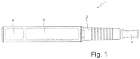
- number 1 indicates as a whole a electronic-cigarette.
- the electronic-cigarette comprises a tubular body 2, which has a front compartment in which a disposable cartridge 3 (i.e. for single use) is housed filled with a viscous liquid substance (for example propylene glycol) containing nicotine and possible flavourings. Furthermore, in the front compartment of the tubular body 2 a controlling device 4 is housed, which is electrically connected to the disposable cartridge 3 for controlling the heating of the disposable cartridge 3 itself so as to determine in use the slow vapourization of the liquid substance contained in the disposable cartridge 3; the vapours produced by heating the liquid substance flow along the tubular body 2 until reaching a mouthpiece 5.
- a controlling device 4 is housed, which is electrically connected to the disposable cartridge 3 for controlling the heating of the disposable cartridge 3 itself so as to determine in use the slow vapourization of the liquid substance contained in the disposable cartridge 3; the vapours produced by heating the liquid substance flow along the tubular body 2 until reaching a mouthpiece 5.
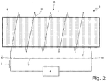
- the disposable cartridge 3 comprises a cylindrical-shaped hygroscopic pad 6 which is impregnated with the liquid substance (i.e. the hygroscopic pad 6 internally contains a certain amount of liquid substance which impregnates the hygroscopic pad 6 itself).
- the pad 6 can be formed by means of hygroscopic glass and silica fibres (that resist without damage to very high temperatures above 1000°C), or can be made from less costly materials such as cellulose acetate (commonly used to make traditional cigarette filters).
- the hygroscopic pad 6 is provided with a surface covering 7, which is located on the outside of the hygroscopic pad 6 and completely covers the hygroscopic pad 6 itself.
- the surface covering 7 is impermeable to liquids (i.e. prevents the passage of liquids so as to prevent the liquid substance, in the liquid state, from leaking from the hygroscopic pad 6) and, at the same time, it is permeable to gas (i.e. allows the passage of gas so as to allow the outflow of the liquid substance, in the vapourous state, from the hygroscopic pad 6).
- the surface covering 7 being permeable to gas allows the passage of both vapour (outflowing from the hygroscopic pad 6), and air (inflowing to the hygroscopic pad 6 and outflowing from the hygroscopic pad 6).
- the surface covering 7 which has high impermeable capability (i.e. is impermeable to polar and apolar liquids) and transpiring (i.e. permeable to gas) is made from polytetrafluoroethylene (PTFE) thermo-mechanically expanded so as to be microporous.
- PTFE polytetrafluoroethylene
- the coating has many microscopic holes (of the order of billions per square centimeter), each of which is much smaller (thousands of times) than a drop of water, but allows the passage of gas, making the coating at the same time impermeable and transpiring.
- the surface covering 7 is made by means of silica and inert material based nano-technological treatments.
- the surface covering 7 adheres directly to an outer surface of the hygroscopic pad 6, i.e. the surface covering 7 is applied directly (for example as a covering paint) to the outer surface of the hygroscopic pad 6.
- a liner (obviously of a material at least permeable to gas) which encloses the hygroscopic pad 6 and supports the surface covering 7 is provided; in other words, the hygroscopic pad 6 is completely enclosed by the liner 7 and the surface covering is applied to the liner itself.
- the disposable cartridge 3 comprises an electric heating resistor 8, which is fitted (thermally) to the hygroscopic pad 6.
- the electric heating resistor 8 is constituted by a metallic conducting wire 9, which is wound in a spiral around the hygroscopic pad 6.
- the electric heating resistor 8 is printed on the outer surface of the hygroscopic pad 6 using conductive inks (e.g. an ink of silver, carbon or copper nanoparticles).
- the electric heating resistor 8 rests on the surface covering 7 of the hygroscopic pad 6, i.e. in direct contact with the surface covering 7 of the hygroscopic pad 6.
- the electric heating resistor 8 has two terminals (terminals, ends) 10, to which the controlling device 4 is connected; in use, the controlling device 4 applies a voltage V to the terminals 10 of the electric heating resistor 8 to circulate through the electric heating resistor 8 a current I which determines heating, by Joule effect, of the electric heating resistor 8 itself; said heating of electric heating resistor 8 itself determines the slow evapouration of the liquid substance contained in the hygroscopic pad 6 of the disposable cartridge 3.
- the controlling device 4 estimates the actual temperature of the electric heating resistor 8, and then varies the voltage V applied to the terminals 10 of the electric heating resistor 8 according to the actual temperature of the electric heating resistor 8 (typically to maintain the actual temperature of the electric heating resistor 8 at about a predetermined desired value). In this way, the controlling device 4 avoids to excessively heat the hygroscopic pad 6 (particularly when the hygroscopic pad 6 is empty, i.e. devoid of the liquid substance due to the depletion of the liquid substance itself). According to a preferred embodiment, the controlling device 4 estimates the actual temperature of the electric heating resistor 8 as a function of an actual electric resistance of the electric heating resistor 8 (i.e. the actual electric resistance revealed at the terminals 10).
- the controlling device 4 determines (measures or estimates) the voltage V applied to the terminals 10 of the electric heating resistor 8, determines (measures or estimates) the intensity of the current I that circulates through the electric heating resistor 8, and then calculates the actual resistance of the electric heating resistor 8 by dividing the voltage V applied to the terminals 10 of the electric heating resistor 8 by the intensity of the current I that circulates through the electric heating resistor 8.
- the electric heating resistor 8 estimates the actual temperature of the electric heating resistor 8 directly as a function of the actual resistance of the electric heating resistor 8.
- the controlling device 4 compares (for example by means of a bridge), the actual electric resistance of the electric heating resistor 8 with the electric resistance of a sample electric resistor (having a value depending on the desired temperature value of the electric heating resistor 8), and then estimates the actual temperature of the electric heating resistor 8 as a function of the comparison between the actual electric resistance of the electric heating resistor 8 and the electric resistance of the specimen electric resistor.
- the controlling device 4 varies the voltage V applied to the terminals 10 of the electric heating resistor 8 so that the actual electric resistance of the electric heating resistor 8 is identical (as much as possible) to the electric resistance of the sample electric resistor.
- the hygroscopic pad 6 By controlling the temperature of the electric heating resistor 8 excessive heating of the hygroscopic pad 6 is avoided, and then the hygroscopic pad 6 itself can be made in less costly materials that cannot withstand very high temperatures. Moreover, by controlling the temperature of the electric heating resistor 8 the health of the smoker is protected, as excessive heating of the hygroscopic pad 6 it prevented (for example when the hygroscopic pad 6 is dry, i.e. devoid of liquid substance that by vapourizing limits the maximum temperature of the hygroscopic pad 6 itself), thus avoiding that the hygroscopic pad 6, subjected to high temperatures, can release gas that is potentially toxic or otherwise undesirable although harmless.
- the controlling device 4 estimates the amount of electrical energy that has been consumed overall by the electric heating resistor 8 during heating (or the total amount of electrical energy that was absorbed by the electric heating resistor 8 from the beginning of its implementation) and then estimates the amount of liquid substance that has been evapourated as a function of the amount of electrical energy that has been consumed overall by the electric heating resistor 8 during heating.
- the controlling device 4 estimates the amount of electrical energy that has been consumed overall by the electric heating resistor 8 during heating (or the total amount of electrical energy that was absorbed by the electric heating resistor 8 from the beginning of its implementation) and then estimates the amount of liquid substance that has been evapourated as a function of the amount of electrical energy that has been consumed overall by the electric heating resistor 8 during heating.
- the controlling device 4 can estimate the amount of liquid substance that was evapourated and, by simply subtracting it from the amount of initial liquid substance, it can then determine the amount of liquid substance remaining in the hygroscopic pad 6 of the disposable cartridge 3.
- the relationship between the amount of electrical energy that has been consumed overall by the electric heating resistor 8 during heating and the amount of liquid substance that has been evapourated is generally determined experimentally.
- the electrical energy absorbed by the electric heating resistor 8 during heating is estimated by integrating over time the electrical power consumed by the electric heating resistor 8 during heating; the electrical power absorbed by the electric heating resistor 8 during heating is normally calculated by multiplying the voltage V (measured or estimated) applied to the terminals 10 of the electric heating resistor 8 by the intensity (measured or estimated) of the current I that circulates through the electric heating resistor 8.
- the disposable cartridge 3 comprises a moisture sensor 11 fitted to the hygroscopic pad 6 of the disposable cartridge 3 for determining the content of liquid substance inside the hygroscopic pad 6 itself.
- the moisture sensor 11 is a capacitive type and comprises a conducting element 12, which is applied to an outer surface of the hygroscopic pad 6 and is connected to a terminal (terminal/end) 13, and a conducting element 14, which is applied to the outer surface of the hygroscopic pad 6, is electrically insulated from the conducting element 12, is located in proximity to the conducting element 12, and fishes at a terminal (terminal/end) 15.
- each conducting element 12 or 14 is comb-shaped and has a plurality of teeth which penetrate without contact between the teeth of the other conducting element 14 or 12.
- the conducting elements 24 and 14 of the moisture sensor 11 are printed on the outer surface of the hygroscopic pad 6 using conductive inks (such as an ink of silver, carbon or copper nanoparticles).
- the controlling device 4 determines (measures) the actual capacitance at the end of terminals 13 and 15 and therefore according to the actual capacitance at the end of terminals 13 and 15 estimates the content of liquid substance inside the hygroscopic pad 6 of the disposable cartridge 3; in other words, the electric capacitance measured between the two terminals 13 and 15 depends upon the quantity of liquid substance inside the hygroscopic pad 6 and increases as the amount of liquid substance inside the hygroscopic pad 6 increases.
- the relation between the actual capacitance at the ends of the terminals 13 and 15 and the quantity of the liquid substance contained inside the hygroscopic pad 6 of the disposable cartridge 3 is normally determined in an experimental way.
- the ability to estimate with high accuracy the amount of liquid substance contained inside the hygroscopic pad 6 of the disposable cartridge 3 allows to inform the user in advance when the disposable cartridge 3 is close to be completely empty avoiding the user to be caught by surprise (i.e. without a new , spare disposable cartridge 3) by the emptying of the disposable cartridge 3 in use.
- the ability to estimate with high precision the quantity of liquid substance contained inside the hygroscopic pad 6 of the disposable cartridge 3 allows to interrupt the heating of an already emptied disposable cartridge 3 avoiding to unnecessarily heat the exhausted hygroscopic pad 6 (in this way preventing that the temperature of the hygroscopic pad 6, no longer mitigated by the latent evapouration heat of the liquid substance, can reach high values that could cause the generation of potentially toxic or otherwise unwanted although harmless volatile substances).
- the hygroscopic pad 6 is initially prepared and then the surface covering 7 is applied to the hygroscopic pad 6 (impermeable to liquids and permeable to gas), which is located outside the hygroscopic pad 6 and completely covers the hygroscopic pad 6 itself.
- the surface covering 7 is applied to the hygroscopic pad 6, the hygroscopic pad 6 itself is impregnated with the liquid substance which vapourizes in use; in other words, the hygroscopic pad 6 is impregnated with the liquid substance after applying the surface covering 7.
- the hygroscopic pad 6 is impregnated with the liquid substance using a needle which locally penetrates the hygroscopic pad 6 and therefore allows to inject the liquid substance directly inside the hygroscopic pad 6 overcoming the liquid barrier formed by the surface covering 7 (obviously the needle receives the liquid substance under pressure by a feed device which can for example be shaped as a syringe).
- the needle is withdrawn from the hygroscopic pad 6; the small hole in the surface covering 7 determined by the penetration of the needle closes spontaneously by elastic return of the hygroscopic pad 6 and therefore does not determine appreciable loss of liquid substance from the hygroscopic pad 6.
- the disposable cartridge 3 described above has numerous advantages.
- the disposable cartridge 3 described above has a very low production cost, as compared to a similar known disposable cartridge is completely devoid of an outer rigid container (i.e. completely devoid of rigid materials that require an assembly process).
- the disposable cartridge 3 described above has a low environmental impact as, compared to a similar known disposable cartridge, it is entirely without external rigid container (i.e. totally devoid of rigid materials).
- the disposable cartridge 3 described above can be (almost) completely biodegradable in a relatively short time, and then in addition to being environmentally friendly may not even require any type of recycling of the used disposable cartridges 3.
- the permeability of the hygroscopic pad 6 to air allows to facilitate mixing between the vapour that is released from the hygroscopic pad 6 and the outside air thus reducing the risk of scalding by steam (saturated steam transposes a large amount of latent heat, while dry air has a very low thermal conductivity and even at temperatures of hundreds of degrees does not cause damage to mucous membranes).
Claims (13)
- Cartouche de cigarettes électroniques jetable (3) ; la cartouche jetable (3) comprenant :un tampon hygroscopique (6) ; etune substance liquide qui imprègne le tampon hygroscopique (6) et est vaporisée en utilisation ;la cartouche jetable (3) étant caractérisée en ce qu'elle comprend un recouvrement de surface (7) qui est situé sur l'extérieur du tampon hygroscopique (6), recouvre totalement le tampon hygroscopique (6), est imperméable aux liquides, et est perméable aux gaz.
- Cartouche jetable (3) selon la revendication 1, dans laquelle le recouvrement de surface (7) est imperméable aux liquides pour empêcher la substance liquide de fuir à l'état liquide depuis le tampon hygroscopique (6), et est perméable aux gaz pour permettre à la substance liquide de sortir à l'état de vapeur du tampon hygroscopique (6).
- Cartouche jetable (3) selon la revendication 1 ou 2, dans laquelle le recouvrement de surface (7) adhère directement à une surface extérieure du tampon hygroscopique (6).
- Cartouche jetable (3) selon la revendication 1 ou 2, et comprenant une doublure qui renferme le tampon hygroscopique (6) et supporte le recouvrement de surface (7).
- Cartouche jetable (3) selon l'une des revendications 1 à 4, et comprenant une résistance chauffante électrique (8) installée sur le tampon hygroscopique (6).
- Cartouche jetable (3) selon la revendication 5, dans laquelle la résistance chauffante électrique (8) repose sur le recouvrement de surface (7) du tampon hygroscopique (6).
- Cartouche jetable (3) selon l'une des revendications 1 à 6, et comprenant un capteur d'humidité (11) installé sur le tampon hygroscopique (6) pour déterminer la teneur en substance liquide du tampon hygroscopique (6).
- Cartouche jetable (3) selon la revendication 7, dans laquelle le capteur d'humidité (11) est d'un type capacitif.
- Cartouche jetable (3) selon la revendication 8, dans laquelle le capteur d'humidité (11) comprend :un premier élément conducteur (12) appliqué à une surface extérieure du tampon hygroscopique (6) et connecté à une première borne (13) ; etun second élément conducteur (14) qui est appliqué à une surface extérieure du tampon hygroscopique (6), est isolé électriquement du premier élément conducteur (12), est situé près du premier élément conducteur (12), et est connecté à une seconde borne (15).
- Cartouche jetable (3) selon la revendication 9, dans laquelle chaque élément conducteur (12 ; 14) est en forme de peigne, et a un nombre de dents qui pénètrent, sans entrer en contact, entre les dents de l'autre élément conducteur (14 ; 12) .
- Cartouche jetable (3) selon la revendication 9 ou 10, dans laquelle la capacitance mesurée entre les deux bornes (13, 15) dépend de la quantité de substance liquide à l'intérieur du tampon hygroscopique (6), et augmente conjointement à une augmentation de la quantité de substance liquide à l'intérieur du tampon hygroscopique (6).
- Procédé de production d'une cartouche de cigarettes électroniques jetable (3) ; le procédé comprenant les étapes de :préparation d'un tampon hygroscopique (6) ; etimprégnation du tampon hygroscopique (6) d'une substance liquide qui est vaporisée en utilisation ;le procédé étant caractérisé en ce qu'il comprend l'étape supplémentaire d'application au tampon hygroscopique (6) d'un recouvrement de surface (7) qui est situé sur l'extérieur du tampon hygroscopique (6), recouvre totalement le tampon hygroscopique (6), est imperméable aux liquides, et est perméable aux gaz.
- Procédé selon la revendication 12, dans lequel le tampon hygroscopique (6) est imprégné de la substance liquide après que le recouvrement de surface (7) est appliqué, et utilisant une aiguille qui pénètre localement dans le tampon hygroscopique (6).
Priority Applications (1)
| Application Number | Priority Date | Filing Date | Title |
|---|---|---|---|
| PL15721845T PL3125710T3 (pl) | 2014-04-01 | 2015-04-01 | Wkład jednorazowego użytku dla elektronicznych papierosów oraz odpowiedni sposób wytwarzania |
Applications Claiming Priority (2)
| Application Number | Priority Date | Filing Date | Title |
|---|---|---|---|
| ITBO20140181 | 2014-04-01 | ||
| PCT/IB2015/052411 WO2015151053A2 (fr) | 2014-04-01 | 2015-04-01 | Cartouche de cigarette électronique jetable, et procédé de fabrication correspondant |
Publications (2)
| Publication Number | Publication Date |
|---|---|
| EP3125710A2 EP3125710A2 (fr) | 2017-02-08 |
| EP3125710B1 true EP3125710B1 (fr) | 2018-07-04 |
Family
ID=50897694
Family Applications (1)
| Application Number | Title | Priority Date | Filing Date |
|---|---|---|---|
| EP15721845.4A Not-in-force EP3125710B1 (fr) | 2014-04-01 | 2015-04-01 | Cartouche de cigarette électronique jetable, et procédé de fabrication correspondant |
Country Status (5)
| Country | Link |
|---|---|
| US (1) | US10299512B2 (fr) |
| EP (1) | EP3125710B1 (fr) |
| JP (1) | JP2017517246A (fr) |
| PL (1) | PL3125710T3 (fr) |
| WO (1) | WO2015151053A2 (fr) |
Families Citing this family (34)
| Publication number | Priority date | Publication date | Assignee | Title |
|---|---|---|---|---|
| US10244793B2 (en) | 2005-07-19 | 2019-04-02 | Juul Labs, Inc. | Devices for vaporization of a substance |
| US10279934B2 (en) | 2013-03-15 | 2019-05-07 | Juul Labs, Inc. | Fillable vaporizer cartridge and method of filling |
| US10980273B2 (en) | 2013-11-12 | 2021-04-20 | VMR Products, LLC | Vaporizer, charger and methods of use |
| KR102256886B1 (ko) | 2013-12-23 | 2021-05-31 | 쥴 랩스, 인크. | 기화 디바이스 시스템 및 방법 |
| USD842536S1 (en) | 2016-07-28 | 2019-03-05 | Juul Labs, Inc. | Vaporizer cartridge |
| USD825102S1 (en) | 2016-07-28 | 2018-08-07 | Juul Labs, Inc. | Vaporizer device with cartridge |
| US20160366947A1 (en) | 2013-12-23 | 2016-12-22 | James Monsees | Vaporizer apparatus |
| US10058129B2 (en) | 2013-12-23 | 2018-08-28 | Juul Labs, Inc. | Vaporization device systems and methods |
| US10159282B2 (en) | 2013-12-23 | 2018-12-25 | Juul Labs, Inc. | Cartridge for use with a vaporizer device |
| US10076139B2 (en) | 2013-12-23 | 2018-09-18 | Juul Labs, Inc. | Vaporizer apparatus |
| US10058123B2 (en) * | 2014-07-11 | 2018-08-28 | R. J. Reynolds Tobacco Company | Heater for an aerosol delivery device and methods of formation thereof |
| KR102627987B1 (ko) | 2014-12-05 | 2024-01-22 | 쥴 랩스, 인크. | 교정된 투여량 제어 |
| US10701981B2 (en) | 2015-04-22 | 2020-07-07 | Altria Client Services Llc | Pod assembly and e-vapor apparatus including the same |
| US9999258B2 (en) | 2015-04-22 | 2018-06-19 | Altria Client Services Llc | Pod assembly, dispensing body, and e-vapor apparatus including the same |
| RU2706837C2 (ru) * | 2015-09-24 | 2019-11-21 | Филип Моррис Продактс С.А. | Изделие, генерирующее аэрозоль, с конденсатором |
| MX2018009703A (es) | 2016-02-11 | 2019-07-08 | Juul Labs Inc | Cartuchos de fijacion segura para dispositivos vaporizadores. |
| SG11201806793TA (en) | 2016-02-11 | 2018-09-27 | Juul Labs Inc | Fillable vaporizer cartridge and method of filling |
| US11006668B2 (en) * | 2016-02-12 | 2021-05-18 | Altria Client Services Llc | Aerosol-generating system with electrodes |
| US10405582B2 (en) | 2016-03-10 | 2019-09-10 | Pax Labs, Inc. | Vaporization device with lip sensing |
| USD849996S1 (en) | 2016-06-16 | 2019-05-28 | Pax Labs, Inc. | Vaporizer cartridge |
| USD851830S1 (en) | 2016-06-23 | 2019-06-18 | Pax Labs, Inc. | Combined vaporizer tamp and pick tool |
| USD836541S1 (en) | 2016-06-23 | 2018-12-25 | Pax Labs, Inc. | Charging device |
| US11147315B2 (en) | 2016-07-25 | 2021-10-19 | Fontem Holdings 1 B.V. | Controlling an operation of an electronic cigarette |
| CN106820266A (zh) * | 2016-09-19 | 2017-06-13 | 卓尔悦欧洲控股有限公司 | 一种电子烟及其控制方法 |
| KR102327122B1 (ko) | 2016-12-12 | 2021-11-16 | 브이엠알 프로덕츠 엘엘씨 | 기화기 카트리지 |
| CN107156911A (zh) | 2017-05-27 | 2017-09-15 | 深圳市合元科技有限公司 | 电子烟及使用方法 |
| USD887632S1 (en) | 2017-09-14 | 2020-06-16 | Pax Labs, Inc. | Vaporizer cartridge |
| CN107536100B (zh) * | 2017-09-26 | 2022-12-30 | 南通烟滤嘴有限责任公司 | 一种具有腔体式容器段的加热不燃烧卷烟 |
| WO2019237052A1 (fr) | 2018-06-07 | 2019-12-12 | Juul Labs, Inc. | Cartouches pour dispositifs de vaporisateur |
| JP7411634B2 (ja) * | 2018-08-08 | 2024-01-11 | ジー.デー ソチエタ ペル アツィオニ | 電子たばこ用使い捨てカートリッジの生産のための生産設備 |
| GB201906516D0 (en) * | 2019-05-09 | 2019-06-26 | E Breathe Ltd | Improvements relating to electronic vapourisers |
| CN112385896A (zh) * | 2019-08-13 | 2021-02-23 | 金箭印刷科技(昆山)有限公司 | 用于制备干化纸制品的一贯化自动化生产机台以及其制备方法 |
| EP3782492A1 (fr) * | 2019-08-23 | 2021-02-24 | Nerudia Limited | Consommable à fumer de substitution |
| WO2023084196A1 (fr) * | 2021-11-10 | 2023-05-19 | Nicoventures Trading Limited | Dispositif de fourniture d'aérosol doté d'un capteur d'humidité |
Family Cites Families (24)
| Publication number | Priority date | Publication date | Assignee | Title |
|---|---|---|---|---|
| US3911080A (en) * | 1971-09-10 | 1975-10-07 | Wright H Dudley | Air pollution control |
| US4182743A (en) * | 1975-11-10 | 1980-01-08 | Philip Morris Incorporated | Filter material for selective removal of aldehydes for cigarette smoke |
| US4941483A (en) * | 1989-09-18 | 1990-07-17 | R. J. Reynolds Tobacco Company | Aerosol delivery article |
| TW245766B (fr) * | 1992-09-11 | 1995-04-21 | Philip Morris Prod | |
| KR100289448B1 (ko) | 1997-07-23 | 2001-05-02 | 미즈노 마사루 | 향미발생장치 |
| US9675109B2 (en) * | 2005-07-19 | 2017-06-13 | J. T. International Sa | Method and system for vaporization of a substance |
| CN201067079Y (zh) * | 2006-05-16 | 2008-06-04 | 韩力 | 仿真气溶胶吸入器 |
| WO2008029381A2 (fr) * | 2006-09-05 | 2008-03-13 | Oglesby & Butler Research & Development Limited | Contenant comprenant une matière vaporisable, utilisé dans un dispositif de vaporisation afin de permettre la vaporisation d'un constituant vaporisable de cette dernière |
| US7726320B2 (en) | 2006-10-18 | 2010-06-01 | R. J. Reynolds Tobacco Company | Tobacco-containing smoking article |
| EP2110033A1 (fr) | 2008-03-25 | 2009-10-21 | Philip Morris Products S.A. | Procédé pour le contrôle de la formation de constituants de fumée dans un système électrique de génération d'aérosol |
| WO2011009920A1 (fr) * | 2009-07-22 | 2011-01-27 | Wedegree Gmbh | Produit de substitution de cigarette sans fumée |
| US8897628B2 (en) | 2009-07-27 | 2014-11-25 | Gregory D. Conley | Electronic vaporizer |
| EP2340729A1 (fr) * | 2009-12-30 | 2011-07-06 | Philip Morris Products S.A. | Chauffage amélioré pour système de génération d'aérosol chauffé électriquement |
| JP2012029633A (ja) * | 2010-07-30 | 2012-02-16 | Jbs:Kk | 電子タバコ |
| EP3508083B1 (fr) * | 2010-08-24 | 2021-07-14 | JT International S.A. | Dispositif d'inhalation comprenant des commandes d'usage de substance |
| CN102160906B (zh) * | 2010-11-01 | 2012-08-08 | 常州市富艾发进出口有限公司 | 口吸式便携雾化器 |
| EP2468118A1 (fr) | 2010-12-24 | 2012-06-27 | Philip Morris Products S.A. | Système de génération d'aérosol afin de désactiver un consommable |
| US9351522B2 (en) * | 2011-09-29 | 2016-05-31 | Robert Safari | Cartomizer e-cigarette |
| US20130255702A1 (en) | 2012-03-28 | 2013-10-03 | R.J. Reynolds Tobacco Company | Smoking article incorporating a conductive substrate |
| US9814262B2 (en) | 2012-07-11 | 2017-11-14 | Sis Resources, Ltd. | Hot-wire control for an electronic cigarette |
| DE102012108477A1 (de) | 2012-09-11 | 2014-03-13 | SNOKE GmbH & Co. KG | Mundstückverschluss für ein Mundstück einer elektrischen Zigarette |
| DE202013010359U1 (de) | 2013-11-18 | 2014-01-07 | Steamo Gmbh | Elektrische Zigarette |
| US9974334B2 (en) * | 2014-01-17 | 2018-05-22 | Rai Strategic Holdings, Inc. | Electronic smoking article with improved storage of aerosol precursor compositions |
| MX2018014310A (es) * | 2016-05-31 | 2019-02-25 | Philip Morris Products Sa | Sistema generador de aerosol que comprende un articulo generador de aerosol calentado. |
-
2015
- 2015-04-01 JP JP2016559534A patent/JP2017517246A/ja not_active Ceased
- 2015-04-01 PL PL15721845T patent/PL3125710T3/pl unknown
- 2015-04-01 US US15/127,830 patent/US10299512B2/en not_active Expired - Fee Related
- 2015-04-01 EP EP15721845.4A patent/EP3125710B1/fr not_active Not-in-force
- 2015-04-01 WO PCT/IB2015/052411 patent/WO2015151053A2/fr active Application Filing
Non-Patent Citations (1)
| Title |
|---|
| None * |
Also Published As
| Publication number | Publication date |
|---|---|
| JP2017517246A (ja) | 2017-06-29 |
| US10299512B2 (en) | 2019-05-28 |
| WO2015151053A2 (fr) | 2015-10-08 |
| WO2015151053A3 (fr) | 2016-01-07 |
| EP3125710A2 (fr) | 2017-02-08 |
| US20170095000A1 (en) | 2017-04-06 |
| PL3125710T3 (pl) | 2018-10-31 |
Similar Documents
| Publication | Publication Date | Title |
|---|---|---|
| EP3125710B1 (fr) | Cartouche de cigarette électronique jetable, et procédé de fabrication correspondant | |
| US11116916B2 (en) | Vapor-generating article with volatile substrate, and a vapor-generating system with the vapor-generating article | |
| RU2726762C2 (ru) | Комбинированный картридж для электронного вейпингового устройства | |
| RU2728073C2 (ru) | Электронное устройство для парения и набор | |
| RU2724175C2 (ru) | Блок ароматизирующего вещества для электронного устройства для вейпинга | |
| RU2739019C2 (ru) | Негорючий вейпинговый элемент с табачной вставкой | |
| RU2678817C2 (ru) | Образующие аэрозоль устройства, содержащие взаимно переплетенные фитиль и нагревательный элемент | |
| KR102194730B1 (ko) | 제1히터 및 제2히터를 갖는 에어로졸 생성장치 및 에어로졸 생성장치의 제1히터 및 제2히터의 전력을 제어하는 방법 | |
| KR102476998B1 (ko) | 전자 베이핑 장치 | |
| RU2727856C2 (ru) | Электронное устройство для парения | |
| EP3525608B1 (fr) | Conception et application d'une cartouche à chambres multiples comprenant une formulation d'hydrogel | |
| DE102017111119B4 (de) | Verdampfereinheit für einen Inhalator | |
| RU2600915C1 (ru) | Нагреваемое устройство, генерирующее аэрозоль, и способ генерирования аэрозоля с устойчивыми свойствами | |
| UA126983C2 (uk) | Пристрій для генерування аерозолю з нагрівачем | |
| RU2635970C2 (ru) | Электронное курительное изделие и улучшенный нагревательный элемент | |
| JP2021503932A (ja) | エアロゾル発生装置およびエアロゾル発生装置のヒーターを制御するための方法 | |
| KR20190126865A (ko) | 흡연 가능한 재료를 휘발시키기 위한 장치 및 흡연 물품 | |
| CN105142443A (zh) | 电子吸烟器具 | |
| KR102500897B1 (ko) | 에어로졸 발생 시스템용 히터 및 심지 조립체 | |
| EA039061B1 (ru) | Система генерирования аэрозоля со средством блокирования потребляемой части | |
| MX2014006834A (es) | Un dispositivo generador de aerosol con una interfaz capilar. | |
| KR20200020690A (ko) | E-베이핑 장치용 캡슐화된 성분 및 그 제조 방법 | |
| JP7367146B2 (ja) | eベイピング装置のための折り畳み可能な繊維基質貯蔵部 | |
| JP2019502403A (ja) | 不燃性喫煙装置およびその要素 | |
| CN209769009U (zh) | 一种具有刺破型发热元件的电子烟雾化芯 |
Legal Events
| Date | Code | Title | Description |
|---|---|---|---|
| STAA | Information on the status of an ep patent application or granted ep patent |
Free format text: STATUS: THE INTERNATIONAL PUBLICATION HAS BEEN MADE |
|
| PUAI | Public reference made under article 153(3) epc to a published international application that has entered the european phase |
Free format text: ORIGINAL CODE: 0009012 |
|
| STAA | Information on the status of an ep patent application or granted ep patent |
Free format text: STATUS: REQUEST FOR EXAMINATION WAS MADE |
|
| 17P | Request for examination filed |
Effective date: 20161020 |
|
| AK | Designated contracting states |
Kind code of ref document: A2 Designated state(s): AL AT BE BG CH CY CZ DE DK EE ES FI FR GB GR HR HU IE IS IT LI LT LU LV MC MK MT NL NO PL PT RO RS SE SI SK SM TR |
|
| AX | Request for extension of the european patent |
Extension state: BA ME |
|
| DAV | Request for validation of the european patent (deleted) | ||
| DAX | Request for extension of the european patent (deleted) | ||
| GRAP | Despatch of communication of intention to grant a patent |
Free format text: ORIGINAL CODE: EPIDOSNIGR1 |
|
| STAA | Information on the status of an ep patent application or granted ep patent |
Free format text: STATUS: GRANT OF PATENT IS INTENDED |
|
| INTG | Intention to grant announced |
Effective date: 20180104 |
|
| RIN1 | Information on inventor provided before grant (corrected) |
Inventor name: SPIRITO, GILBERTO Inventor name: NEGRINI, STEFANO |
|
| GRAJ | Information related to disapproval of communication of intention to grant by the applicant or resumption of examination proceedings by the epo deleted |
Free format text: ORIGINAL CODE: EPIDOSDIGR1 |
|
| STAA | Information on the status of an ep patent application or granted ep patent |
Free format text: STATUS: REQUEST FOR EXAMINATION WAS MADE |
|
| GRAR | Information related to intention to grant a patent recorded |
Free format text: ORIGINAL CODE: EPIDOSNIGR71 |
|
| GRAS | Grant fee paid |
Free format text: ORIGINAL CODE: EPIDOSNIGR3 |
|
| STAA | Information on the status of an ep patent application or granted ep patent |
Free format text: STATUS: GRANT OF PATENT IS INTENDED |
|
| GRAA | (expected) grant |
Free format text: ORIGINAL CODE: 0009210 |
|
| STAA | Information on the status of an ep patent application or granted ep patent |
Free format text: STATUS: THE PATENT HAS BEEN GRANTED |
|
| INTC | Intention to grant announced (deleted) | ||
| INTG | Intention to grant announced |
Effective date: 20180524 |
|
| AK | Designated contracting states |
Kind code of ref document: B1 Designated state(s): AL AT BE BG CH CY CZ DE DK EE ES FI FR GB GR HR HU IE IS IT LI LT LU LV MC MK MT NL NO PL PT RO RS SE SI SK SM TR |
|
| REG | Reference to a national code |
Ref country code: GB Ref legal event code: FG4D |
|
| REG | Reference to a national code |
Ref country code: CH Ref legal event code: EP |
|
| REG | Reference to a national code |
Ref country code: AT Ref legal event code: REF Ref document number: 1013561 Country of ref document: AT Kind code of ref document: T Effective date: 20180715 |
|
| REG | Reference to a national code |
Ref country code: IE Ref legal event code: FG4D |
|
| REG | Reference to a national code |
Ref country code: CH Ref legal event code: NV Representative=s name: ANDRE ROLAND S.A., CH |
|
| REG | Reference to a national code |
Ref country code: DE Ref legal event code: R096 Ref document number: 602015013036 Country of ref document: DE |
|
| REG | Reference to a national code |
Ref country code: NL Ref legal event code: MP Effective date: 20180704 |
|
| REG | Reference to a national code |
Ref country code: LT Ref legal event code: MG4D |
|
| REG | Reference to a national code |
Ref country code: AT Ref legal event code: MK05 Ref document number: 1013561 Country of ref document: AT Kind code of ref document: T Effective date: 20180704 |
|
| PG25 | Lapsed in a contracting state [announced via postgrant information from national office to epo] |
Ref country code: NL Free format text: LAPSE BECAUSE OF FAILURE TO SUBMIT A TRANSLATION OF THE DESCRIPTION OR TO PAY THE FEE WITHIN THE PRESCRIBED TIME-LIMIT Effective date: 20180704 |
|
| PG25 | Lapsed in a contracting state [announced via postgrant information from national office to epo] |
Ref country code: CZ Free format text: LAPSE BECAUSE OF FAILURE TO SUBMIT A TRANSLATION OF THE DESCRIPTION OR TO PAY THE FEE WITHIN THE PRESCRIBED TIME-LIMIT Effective date: 20180704 Ref country code: FI Free format text: LAPSE BECAUSE OF FAILURE TO SUBMIT A TRANSLATION OF THE DESCRIPTION OR TO PAY THE FEE WITHIN THE PRESCRIBED TIME-LIMIT Effective date: 20180704 Ref country code: AT Free format text: LAPSE BECAUSE OF FAILURE TO SUBMIT A TRANSLATION OF THE DESCRIPTION OR TO PAY THE FEE WITHIN THE PRESCRIBED TIME-LIMIT Effective date: 20180704 Ref country code: SE Free format text: LAPSE BECAUSE OF FAILURE TO SUBMIT A TRANSLATION OF THE DESCRIPTION OR TO PAY THE FEE WITHIN THE PRESCRIBED TIME-LIMIT Effective date: 20180704 Ref country code: BG Free format text: LAPSE BECAUSE OF FAILURE TO SUBMIT A TRANSLATION OF THE DESCRIPTION OR TO PAY THE FEE WITHIN THE PRESCRIBED TIME-LIMIT Effective date: 20181004 Ref country code: IS Free format text: LAPSE BECAUSE OF FAILURE TO SUBMIT A TRANSLATION OF THE DESCRIPTION OR TO PAY THE FEE WITHIN THE PRESCRIBED TIME-LIMIT Effective date: 20181104 Ref country code: LT Free format text: LAPSE BECAUSE OF FAILURE TO SUBMIT A TRANSLATION OF THE DESCRIPTION OR TO PAY THE FEE WITHIN THE PRESCRIBED TIME-LIMIT Effective date: 20180704 Ref country code: GR Free format text: LAPSE BECAUSE OF FAILURE TO SUBMIT A TRANSLATION OF THE DESCRIPTION OR TO PAY THE FEE WITHIN THE PRESCRIBED TIME-LIMIT Effective date: 20181005 Ref country code: NO Free format text: LAPSE BECAUSE OF FAILURE TO SUBMIT A TRANSLATION OF THE DESCRIPTION OR TO PAY THE FEE WITHIN THE PRESCRIBED TIME-LIMIT Effective date: 20181004 Ref country code: RS Free format text: LAPSE BECAUSE OF FAILURE TO SUBMIT A TRANSLATION OF THE DESCRIPTION OR TO PAY THE FEE WITHIN THE PRESCRIBED TIME-LIMIT Effective date: 20180704 |
|
| PG25 | Lapsed in a contracting state [announced via postgrant information from national office to epo] |
Ref country code: ES Free format text: LAPSE BECAUSE OF FAILURE TO SUBMIT A TRANSLATION OF THE DESCRIPTION OR TO PAY THE FEE WITHIN THE PRESCRIBED TIME-LIMIT Effective date: 20180704 Ref country code: HR Free format text: LAPSE BECAUSE OF FAILURE TO SUBMIT A TRANSLATION OF THE DESCRIPTION OR TO PAY THE FEE WITHIN THE PRESCRIBED TIME-LIMIT Effective date: 20180704 Ref country code: LV Free format text: LAPSE BECAUSE OF FAILURE TO SUBMIT A TRANSLATION OF THE DESCRIPTION OR TO PAY THE FEE WITHIN THE PRESCRIBED TIME-LIMIT Effective date: 20180704 Ref country code: AL Free format text: LAPSE BECAUSE OF FAILURE TO SUBMIT A TRANSLATION OF THE DESCRIPTION OR TO PAY THE FEE WITHIN THE PRESCRIBED TIME-LIMIT Effective date: 20180704 |
|
| REG | Reference to a national code |
Ref country code: DE Ref legal event code: R097 Ref document number: 602015013036 Country of ref document: DE |
|
| PG25 | Lapsed in a contracting state [announced via postgrant information from national office to epo] |
Ref country code: EE Free format text: LAPSE BECAUSE OF FAILURE TO SUBMIT A TRANSLATION OF THE DESCRIPTION OR TO PAY THE FEE WITHIN THE PRESCRIBED TIME-LIMIT Effective date: 20180704 Ref country code: RO Free format text: LAPSE BECAUSE OF FAILURE TO SUBMIT A TRANSLATION OF THE DESCRIPTION OR TO PAY THE FEE WITHIN THE PRESCRIBED TIME-LIMIT Effective date: 20180704 Ref country code: IT Free format text: LAPSE BECAUSE OF FAILURE TO SUBMIT A TRANSLATION OF THE DESCRIPTION OR TO PAY THE FEE WITHIN THE PRESCRIBED TIME-LIMIT Effective date: 20180704 |
|
| PLBE | No opposition filed within time limit |
Free format text: ORIGINAL CODE: 0009261 |
|
| STAA | Information on the status of an ep patent application or granted ep patent |
Free format text: STATUS: NO OPPOSITION FILED WITHIN TIME LIMIT |
|
| PG25 | Lapsed in a contracting state [announced via postgrant information from national office to epo] |
Ref country code: SM Free format text: LAPSE BECAUSE OF FAILURE TO SUBMIT A TRANSLATION OF THE DESCRIPTION OR TO PAY THE FEE WITHIN THE PRESCRIBED TIME-LIMIT Effective date: 20180704 Ref country code: DK Free format text: LAPSE BECAUSE OF FAILURE TO SUBMIT A TRANSLATION OF THE DESCRIPTION OR TO PAY THE FEE WITHIN THE PRESCRIBED TIME-LIMIT Effective date: 20180704 Ref country code: SK Free format text: LAPSE BECAUSE OF FAILURE TO SUBMIT A TRANSLATION OF THE DESCRIPTION OR TO PAY THE FEE WITHIN THE PRESCRIBED TIME-LIMIT Effective date: 20180704 |
|
| 26N | No opposition filed |
Effective date: 20190405 |
|
| PG25 | Lapsed in a contracting state [announced via postgrant information from national office to epo] |
Ref country code: SI Free format text: LAPSE BECAUSE OF FAILURE TO SUBMIT A TRANSLATION OF THE DESCRIPTION OR TO PAY THE FEE WITHIN THE PRESCRIBED TIME-LIMIT Effective date: 20180704 |
|
| REG | Reference to a national code |
Ref country code: CH Ref legal event code: PL |
|
| REG | Reference to a national code |
Ref country code: BE Ref legal event code: MM Effective date: 20190430 |
|
| GBPC | Gb: european patent ceased through non-payment of renewal fee |
Effective date: 20190401 |
|
| PG25 | Lapsed in a contracting state [announced via postgrant information from national office to epo] |
Ref country code: LU Free format text: LAPSE BECAUSE OF NON-PAYMENT OF DUE FEES Effective date: 20190401 Ref country code: MC Free format text: LAPSE BECAUSE OF FAILURE TO SUBMIT A TRANSLATION OF THE DESCRIPTION OR TO PAY THE FEE WITHIN THE PRESCRIBED TIME-LIMIT Effective date: 20180704 |
|
| PG25 | Lapsed in a contracting state [announced via postgrant information from national office to epo] |
Ref country code: LI Free format text: LAPSE BECAUSE OF NON-PAYMENT OF DUE FEES Effective date: 20190430 Ref country code: GB Free format text: LAPSE BECAUSE OF NON-PAYMENT OF DUE FEES Effective date: 20190401 Ref country code: CH Free format text: LAPSE BECAUSE OF NON-PAYMENT OF DUE FEES Effective date: 20190430 |
|
| PG25 | Lapsed in a contracting state [announced via postgrant information from national office to epo] |
Ref country code: BE Free format text: LAPSE BECAUSE OF NON-PAYMENT OF DUE FEES Effective date: 20190430 |
|
| PG25 | Lapsed in a contracting state [announced via postgrant information from national office to epo] |
Ref country code: TR Free format text: LAPSE BECAUSE OF FAILURE TO SUBMIT A TRANSLATION OF THE DESCRIPTION OR TO PAY THE FEE WITHIN THE PRESCRIBED TIME-LIMIT Effective date: 20180704 |
|
| PG25 | Lapsed in a contracting state [announced via postgrant information from national office to epo] |
Ref country code: IE Free format text: LAPSE BECAUSE OF NON-PAYMENT OF DUE FEES Effective date: 20190401 |
|
| PG25 | Lapsed in a contracting state [announced via postgrant information from national office to epo] |
Ref country code: PT Free format text: LAPSE BECAUSE OF FAILURE TO SUBMIT A TRANSLATION OF THE DESCRIPTION OR TO PAY THE FEE WITHIN THE PRESCRIBED TIME-LIMIT Effective date: 20181104 |
|
| PG25 | Lapsed in a contracting state [announced via postgrant information from national office to epo] |
Ref country code: CY Free format text: LAPSE BECAUSE OF FAILURE TO SUBMIT A TRANSLATION OF THE DESCRIPTION OR TO PAY THE FEE WITHIN THE PRESCRIBED TIME-LIMIT Effective date: 20180704 |
|
| PGFP | Annual fee paid to national office [announced via postgrant information from national office to epo] |
Ref country code: PL Payment date: 20210319 Year of fee payment: 7 |
|
| PG25 | Lapsed in a contracting state [announced via postgrant information from national office to epo] |
Ref country code: MT Free format text: LAPSE BECAUSE OF FAILURE TO SUBMIT A TRANSLATION OF THE DESCRIPTION OR TO PAY THE FEE WITHIN THE PRESCRIBED TIME-LIMIT Effective date: 20180704 Ref country code: HU Free format text: LAPSE BECAUSE OF FAILURE TO SUBMIT A TRANSLATION OF THE DESCRIPTION OR TO PAY THE FEE WITHIN THE PRESCRIBED TIME-LIMIT; INVALID AB INITIO Effective date: 20150401 |
|
| PGFP | Annual fee paid to national office [announced via postgrant information from national office to epo] |
Ref country code: DE Payment date: 20210428 Year of fee payment: 7 Ref country code: FR Payment date: 20210426 Year of fee payment: 7 |
|
| PG25 | Lapsed in a contracting state [announced via postgrant information from national office to epo] |
Ref country code: MK Free format text: LAPSE BECAUSE OF FAILURE TO SUBMIT A TRANSLATION OF THE DESCRIPTION OR TO PAY THE FEE WITHIN THE PRESCRIBED TIME-LIMIT Effective date: 20180704 |
|
| REG | Reference to a national code |
Ref country code: DE Ref legal event code: R119 Ref document number: 602015013036 Country of ref document: DE |
|
| PG25 | Lapsed in a contracting state [announced via postgrant information from national office to epo] |
Ref country code: FR Free format text: LAPSE BECAUSE OF NON-PAYMENT OF DUE FEES Effective date: 20220430 Ref country code: DE Free format text: LAPSE BECAUSE OF NON-PAYMENT OF DUE FEES Effective date: 20221103 |
|
| PG25 | Lapsed in a contracting state [announced via postgrant information from national office to epo] |
Ref country code: PL Free format text: LAPSE BECAUSE OF NON-PAYMENT OF DUE FEES Effective date: 20220401 |