EP3125396A1 - Power loss measuring system for measuring power loss at harmonic filter included in high voltage direct current (hvdc) transmission system, and power loss measuring method thereof - Google Patents
Power loss measuring system for measuring power loss at harmonic filter included in high voltage direct current (hvdc) transmission system, and power loss measuring method thereof Download PDFInfo
- Publication number
- EP3125396A1 EP3125396A1 EP16163648.5A EP16163648A EP3125396A1 EP 3125396 A1 EP3125396 A1 EP 3125396A1 EP 16163648 A EP16163648 A EP 16163648A EP 3125396 A1 EP3125396 A1 EP 3125396A1
- Authority
- EP
- European Patent Office
- Prior art keywords
- power loss
- impedance
- elements
- variation
- amount
- Prior art date
- Legal status (The legal status is an assumption and is not a legal conclusion. Google has not performed a legal analysis and makes no representation as to the accuracy of the status listed.)
- Granted
Links
Images


Classifications
-
- G—PHYSICS
- G01—MEASURING; TESTING
- G01R—MEASURING ELECTRIC VARIABLES; MEASURING MAGNETIC VARIABLES
- G01R31/00—Arrangements for testing electric properties; Arrangements for locating electric faults; Arrangements for electrical testing characterised by what is being tested not provided for elsewhere
- G01R31/40—Testing power supplies
-
- G—PHYSICS
- G01—MEASURING; TESTING
- G01R—MEASURING ELECTRIC VARIABLES; MEASURING MAGNETIC VARIABLES
- G01R21/00—Arrangements for measuring electric power or power factor
-
- H—ELECTRICITY
- H02—GENERATION; CONVERSION OR DISTRIBUTION OF ELECTRIC POWER
- H02J—ELECTRIC POWER NETWORKS; CIRCUIT ARRANGEMENTS OR SYSTEMS FOR SUPPLYING OR DISTRIBUTING ELECTRIC POWER; SYSTEMS FOR STORING ELECTRIC ENERGY
- H02J3/00—Circuit arrangements for AC mains or AC distribution networks
- H02J3/01—Arrangements for reducing harmonics or ripples
-
- H—ELECTRICITY
- H02—GENERATION; CONVERSION OR DISTRIBUTION OF ELECTRIC POWER
- H02J—ELECTRIC POWER NETWORKS; CIRCUIT ARRANGEMENTS OR SYSTEMS FOR SUPPLYING OR DISTRIBUTING ELECTRIC POWER; SYSTEMS FOR STORING ELECTRIC ENERGY
- H02J3/00—Circuit arrangements for AC mains or AC distribution networks
- H02J3/36—Arrangements for transfer of electric power between AC networks via high-voltage DC [HVDC] links; Arrangements for transfer of electric power between generators and networks via HVDC links
-
- H—ELECTRICITY
- H02—GENERATION; CONVERSION OR DISTRIBUTION OF ELECTRIC POWER
- H02J—ELECTRIC POWER NETWORKS; CIRCUIT ARRANGEMENTS OR SYSTEMS FOR SUPPLYING OR DISTRIBUTING ELECTRIC POWER; SYSTEMS FOR STORING ELECTRIC ENERGY
- H02J3/00—Circuit arrangements for AC mains or AC distribution networks
- H02J3/36—Arrangements for transfer of electric power between AC networks via high-voltage DC [HVDC] links; Arrangements for transfer of electric power between generators and networks via HVDC links
- H02J2003/365—Reducing harmonics or oscillations in HVDC
-
- Y—GENERAL TAGGING OF NEW TECHNOLOGICAL DEVELOPMENTS; GENERAL TAGGING OF CROSS-SECTIONAL TECHNOLOGIES SPANNING OVER SEVERAL SECTIONS OF THE IPC; TECHNICAL SUBJECTS COVERED BY FORMER USPC CROSS-REFERENCE ART COLLECTIONS [XRACs] AND DIGESTS
- Y02—TECHNOLOGIES OR APPLICATIONS FOR MITIGATION OR ADAPTATION AGAINST CLIMATE CHANGE
- Y02E—REDUCTION OF GREENHOUSE GAS [GHG] EMISSIONS, RELATED TO ENERGY GENERATION, TRANSMISSION OR DISTRIBUTION
- Y02E40/00—Technologies for an efficient electrical power generation, transmission or distribution
- Y02E40/40—Arrangements for reducing harmonics
-
- Y—GENERAL TAGGING OF NEW TECHNOLOGICAL DEVELOPMENTS; GENERAL TAGGING OF CROSS-SECTIONAL TECHNOLOGIES SPANNING OVER SEVERAL SECTIONS OF THE IPC; TECHNICAL SUBJECTS COVERED BY FORMER USPC CROSS-REFERENCE ART COLLECTIONS [XRACs] AND DIGESTS
- Y02—TECHNOLOGIES OR APPLICATIONS FOR MITIGATION OR ADAPTATION AGAINST CLIMATE CHANGE
- Y02E—REDUCTION OF GREENHOUSE GAS [GHG] EMISSIONS, RELATED TO ENERGY GENERATION, TRANSMISSION OR DISTRIBUTION
- Y02E60/00—Enabling technologies; Technologies with a potential or indirect contribution to GHG emissions mitigation
- Y02E60/60—Arrangements for transfer of electric power between AC networks or generators via a high voltage DC link [HVCD]
Definitions
- the present disclosure relates to power loss measuring system for measuring power loss in a harmonic filter using variation in impedance of each element included in the harmonic filter, and a power losing measuring method thereof.
- High Voltage Direct Current (HVDC) transmission indicates a power transmission method of converting, by a transmission site, AC power produced at a power station into DC power to transmit the DC power and then re-converting, by a reception site, the DC power into the AC power to supply power.
- the HVDC transmission may enable efficient and economical power transmission through a voltage increase that is the advantage of AC transmission.
- the HVDC transmission may overcome many limitations of the Ac transmission.
- a general configuration of the harmonic filter is as shown in Fig. 1 .
- the harmonic filter includes at least one inductor, at least one capacitor, and at least one resistor.
- GIS Gas Insulated Switchgear
- an existing system for measuring power loss in a harmonic filter aims mainly to measure voltage and current, rather than the power loss itself.
- it is hard to measure power loss according to a real-time change in temperature and frequency because variation in impedance according to a change in temperature and frequency is not known.
- power loss of each element cannot be measured, and variation in impedance according to a change in a voltage and a current is not known, so that they cannot be reflected in the system design.
- the present disclosure is provided to solve the aforementioned drawbacks, and relates to power loss measuring system, which measures a loss in a harmonic filter based on variation in impedance of each element of the harmonic element, and power loss measuring method thereof.
- a power loss measuring system for measuring power loss in a harmonic filter included in a High Voltage Direct Current (HVDC) transmission system, the power loss measuring system including: the harmonic filter including a plurality of elements; a monitoring sensor unit sensing variation in impedance of the plurality of elements; and a controller obtaining power loss in the harmonic filter using amount of variation in impedance of the plurality of elements.
- HVDC High Voltage Direct Current
- the plurality of elements may include at least one resistor, at least one capacitor, and at least one inductor; the monitoring sensor unit may sense variation in impedance of each of the at least one resistor, the at least one capacitor, and the at least one inductor; and the controller may obtain power loss occurring in each of the at least one resistor, the at least one capacitor, and the at least one inductor based on the amount of variation in impedance of each of the at least one resistor, the at least one capacitor, and the at least one inductor.
- the monitoring sensor unit may obtain the amount of variation in impedance using an impedance value, which is sensed by the monitoring sensor unit, and an initial impedance value of each of the at least one resistor, the at least one capacitor, and the at least one inductor.
- Impedance of the plurality of elements may be changed due to at least one of a change in temperature and a change in frequency of the plurality of elements.
- the controller may obtain the power loss in the harmonic filter using variation in impedance of each of the plurality of elements and at least one of a rated voltage and a rated current of each of the plurality of elements.
- the rated voltage of each of the plurality of elements may be a fixed value.
- the controller may include a communication module communicating with a server, calculate at least one of amount of the power loss in each of the plurality of elements and amount of the power loss in the harmonic filter based on the amount of variation in impedance of each of the plurality of elements, and transmit the at least one of the amount of the power loss in each of the plurality of elements and the power loss in the harmonic filter via the communication module to the server.
- the monitoring sensor unit may comprise a communication module communicating with a server and transmit the amount of variation in impedance of each of the plurality of elements via the communication module to the server.
- the power loss measuring system may further include a storage, wherein the controller stores, in the storage, at least one of an initial impedance value of each of the plurality of elements, amount of variation in impedance of each of the plurality of elements, amount of power loss occurring in each of the plurality of elements, and amount of power loss occurring in the harmonic filter.
- the monitoring sensor unit may sense an impedance value of each of the plurality of elements and transmit the sensed impedance value of each of the plurality of elements to the controller, and the controller may calculate amount of variation in impedance of each of the plurality of elements based on the received impedance value of each of the plurality of elements.
- a power loss measuring method of power loss measuring system for measuring power loss in a harmonic filter included in a High Voltage Direct Current (HVDC) transmission system, the power loss measuring method including: sensing impedance values of a plurality of elements included in the harmonic filter; obtaining variation in impedance of the plurality of elements; and obtaining power loss in the harmonic filter using amount of variation in impedance of the plurality of elements.
- HVDC High Voltage Direct Current
- Fig. 2 is a block diagram illustrating a loss power measuring system according to an embodiment of the present disclosure.
- power loss measuring system 10 may include a harmonic filter 100, a monitoring sensor 200, a controller 300, and storage 400.
- the harmonic filter 100 may remove harmonics occurring in a High Voltage Direct Current (HVDC) system. Specifically, in a HVDC transmission method, a thyristor converter is used to convert AC power into DC power, and harmonics occur during the conversion due to characteristics of the thyristor converter that controls a phase. In addition, the harmonic filter 100 may remove the harmonics that occur during the conversion.
- HVDC High Voltage Direct Current
- the harmonic filter 100 may include a plurality of elements. Specifically, the harmonic filter 100 may include a capacitive element, an inductive element, and a resistor, and may remove n-th harmonics that occur when AC power is rectified.
- a capacitor may be used as the capacitive element, and an inductor may be used as the inductive element.
- the harmonic filter 100 installed in a transceiver of the HVDC system may remove harmonics occurring when AC power is converted into DC power.
- the harmonic filter 100 installed in a receiver of the HVDC system may remove harmonics occurring when DC power is converted into AC power.
- the harmonic filter 100 may improve a power factor by supplying reactive power to the HVDC system.
- the monitoring sensor unit 200 may sense variation in impedance of a plurality of devices.
- the monitoring sensor unit 200 may include a plurality of monitoring sensors which correspond to the number of a capacitive element(s), an inductive element(s), and a resistor(s) included in the harmonic filter 100, and may sense an impedance value of each of the capacitive element(s), the inductive element(s), and the resistor(s) included in the harmonic filter 100.
- the plurality of monitoring sensors obtain amount of variation in impedance using the sensed impedance value, and transmit the obtained amount of variation in impedance to the controller 300.
- each monitoring sensor may calculate the amount of variation in impedance based on the initial impedance value that each capacitive element, inductive element, and resistor has in a specific condition.
- Each monitoring sensor may include a sensing module for sensing impedance of an element, a calculation module for calculating amount of variation in impedance of an element, a communication module for transmitting the calculated amount of variation in impedance to the controller 300.
- each of the plurality monitoring sensor included in the monitoring sensor unit 200 calculates amount of variation in impedance in the above-described embodiment, but aspects of the present disclosure are not limited thereto.
- each of the plurality of monitoring sensors may consist of a sensing component for sensing impedance value of an element and a communicating component for transmitting the sensed impedance value to the controller 300, and amount of variation in impedance may be calculated by the controller 300.
- the controller 300 may measure amount of variation in impedance of a plurality of elements. Specifically, when receiving information on an impedance value of each of the plurality of elements from the monitoring sensor unit 200, the controller 300 may calculate amount of variation in impedance using the received information. More specifically, the controller 300 stores, in the storage 400, an initial impedance value that each capacitive element, inductive element, or resistor has in a specific condition. Then, the controller 300 compares a receive impedance value with a stored initial impedance value to calculate amount of variation in impedance of each element.
- the controller 300 may calculate power loss occurring at the harmonic filter 300. Specifically, by calculating variation in power loss occurring in each element based on calculated amount of variation in impedance of each element included in the harmonic filter 100, the controller 300 may calculate amount of variation in power loss occurring in the harmonic filter 100. In addition, by calculating amount of variation in power loss occurring in each element based on received variation in impedance of each element from the monitoring sensor unit 200, the controller 300 may calculate the amount of variation in the entire power loss occurring in the harmonic filter 100.
- the storage 400 is under control of the controller 300 and may store at least one of the following: an initial impedance value of each element included in the harmonic filter 100, amount of variation in impedance, amount of power loss occurring in each element, and amount of an entire power loss occurring in the harmonic filter 100.
- Fig. 3 is a flowchart illustrating power loss measuring method of power loss measuring system according to an embodiment of the present disclosure.
- power loss measuring method of power loss measuring system may include measuring impedance of a plurality of elements (s310), calculating power loss in a harmonic filter based on amount of variation in impedance of the plurality of elements (S330), and storing data (S350).
- step 310 Measuring impedance of the plurality of elements in step 310 is described in detail with reference to Fig. 4 .
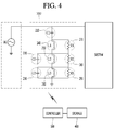
- Fig. 4 is a diagram for explanation of a method for measuring power loss in each of a plurality of elements included in a harmonic filter according to an embodiment of the present disclosure.
- a harmonic filter 100 may include a plurality of elements. Specifically, as shown in Fig. 4 , the harmonic filter 100 may include a plurality of capacitors C1, C2, and C3, a plurality of inductors L1, L2, and L3, and a plurality of resistors R1, R2, and R3, and may remove harmonics equal to higher than a reference level by using a combination of the capacitors, inductors, and resistors. Meanwhile, Fig. 4 shows a harmonic filter including three capacitors, three inductors, and three resistors, but aspects of the present disclosure are not limited thereto. That is, a harmonic filter of the present disclosure may be any filter which is able to remove harmonics by using various combinations of at least one capacitor, at least one inductor, and at least one resistor.
- the plurality of capacitors C1, C2, and C3, the plurality of inductors L1, L2, and L3, and the plurality of resistors R1, R2, and R3 have impedance values, respectively, and the impedance values are able to be changed.
- the impedance values may be changed according to a voltage or a current frequency.
- an impedance value may be changed according to characteristics of an element.
- power loss in each element may be calculated using a change in frequency and temperature, a voltage value, and a current value.
- these values are often changed so accurate measurements thereof are hard to obtain.
- amount of variation in impedance of each element where power loss occurs it is possible to calculate the power loss.
- a plurality of sensors 210, 220, 230, 240, 250, 260, 270, 280, 290 included in the monitoring sensor unit 200 may measure impedance of a plurality of capacitors C1, C2, and C3, impedance of a plurality of inductors L1, L2, and L3, and a plurality of resistors R1, R2, and R3, respectively.
- the plurality of sensors 210, 220, 230, 240, 250, 260, 270, 280, and 290 senses not only amount of variation in impedance of each of a plurality of elements, but also a voltage and current applied to each of the plurality of elements and frequency and temperature of each of the plurality of elements, so that the controller 300 may be enabled to monitor a voltage and a current of each element based on a combination thereof and improve accuracy in calculation of power loss.
- power loss measuring method proposed in the present disclosure it is possible to measure power loss in each element based solely on a change in an impedance value, and thus, it is not essential to measure a voltage and a current.
- the amount of variation in impedance may be a difference between an initial impedance value and a current impedance value of an element.
- the plurality of sensors 210, 220, 230, 240, 250, 260, 270, 280, and 290 may store initial impedance values of respective elements.
- an initial impedance value may be an impedance value that an element has in a basic condition (basic frequency, basic temperature, basic voltage, and basic current).
- the plurality of sensors 210, 220, 230, 240, 250, 260, 270, 280, and 290 may calculate amount of variation in impedance by sensing impedance values of the respective elements and comparing the sensed impedance values with initial impedance values of the respective elements.
- the plurality of sensors 210, 220, 230, 240, 250, 260, 270, 280, and 290 may transmit impedance values measured by the plurality of elements to the controller 300.
- the controller 300 may calculate amount of variation in impedance.
- the impedance values measured by the plurality of elements may be used to calculate power loss in each element without calculating amount of variation in impedance by the controller 300.
- Each of the plurality of sensors 210, 220, 230, 240, 250, 260, 270, 280, and 290 may include a storage module for storing an initial impedance value of a corresponding element, and a calculation module for calculating amount of variation in impedance of a corresponding element.
- each of the plurality of sensors 210, 220, 230, 240, 250, 260, 270, 280, and 290 may include a communication module for transmitting amount of variation in impedance or an impedance value of each element.
- the current value I in each element is a fixed value according to a rated current of the system.
- the fixed current value I and the value of variation of impedance ⁇ Z it is possible to measure variation in power loss in an element.
- the controller 300 may calculate variation in amount of power loss ⁇ W in each of the plurality of elements (the capacitors C1, C2, and C3, the inductors L1, L2, and L3, and the resistors R1, R2, and R3) by using amount of variation in impedance and a rated current value of each of the plurality of the elements (the capacitors C1, C2, and C3, the inductors L1, L2, and L3, and the resistors R1, R2, and R3).
- the voltage value v of each element is a fixed value according to a rated voltage of the system.
- the current value I may be calculated using the fixed voltage value v and an impedance value in each element, and amount of variation in power loss ⁇ W in each element may be calculated using the current value I and the amount of variation in impedance ⁇ Z.
- the voltage value v in each element is a fixed value according to a rated voltage of the system, and amount of variation in power loss ⁇ W in each element may be calculated using the fixed voltage value v and the amount of variation in impedance ⁇ Z.
- the controller 300 may calculate amount of variation in power loss ⁇ W in each element.
- the controller 300 may calculate amount of variation in the entire power loss that occurs in the harmonic filter 100.
- amount of variation in power loss ⁇ W are calculated using amount of variation in impedance ⁇ Z, so the amount of variation in power loss ⁇ W calculated in this embodiment may be an amount of power loss that is changed from amount of power loss which occurs in a basic condition (basic frequency, basic temperature, basic voltage, and basic current).
- this embodiments is a case where the controller 300 calculate amount of variation in power loss in each element based on amount of variation in impedance in each element, which is received from each of the plurality of sensors 210, 220, 230, 240, 250, 260, 270, 280, and 290, but aspects of the present disclosure are not limited thereto.
- the plurality of sensors 210, 220, 230, 240, 250, 260, 270, 280, and 290 may sense impedance value of each of the plurality of elements and transmit the sensed impedance value to the controller 300, and then the controller 300 may calculate amount of variation in impedance of each element by using an initial impedance value of each element, which is stored in the storage 400, and may calculate amount of variation in power loss in each element by using the calculated amount of variation in impedance and a rated voltage of each element.
- the calculated power loss W may be strengthened amount of power loss. Specifically, the power loss W is calculated using the magnitude of impedance
- the controller 300 may calculate power loss occurring in the entire harmonic filter 100.
- the controller 300 may store calculated data in the storage 400. Specifically, the controller 300 may store, in the storage 400, at least one of the following: a voltage value of each element, a current value of each element, temperature of each element, a frequency of each element, an impedance value of each element, amount of variation in impedance of each element, amount of power loss in each element, and amount of variation in power loss in each element, wherein the aforementioned data items are transmitted from the monitoring sensor unit 200.
- the controller 300 may store, in the storage 400, time information which includes at least one measurement of the following: a voltage value of each element, a current value of each element, temperature of each element, a frequency of each element, an impedance value of each element, amount of variation in impedance of each element, amount of power loss in each element, and variation in power loss in each element.
- time information which includes at least one measurement of the following: a voltage value of each element, a current value of each element, temperature of each element, a frequency of each element, an impedance value of each element, amount of variation in impedance of each element, amount of power loss in each element, and variation in power loss in each element.
- the stored data may be used to monitor the plurality of elements and design the system.
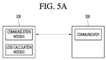
- Fig. 5 is a diagram for explanation of a method of transmitting data to a server according to an embodiment of the present disclosure.
- a controller 300 may transmit, to a server 500, at least one of the following: a voltage value of each element, a current value of each element, temperature of each element, a frequency of each element, an impedance value of each element, amount of variation in impedance of each element, amount of power loss in each element, and amount of variation in power loss in each element, wherein the voltage value, current value, temperature, frequency, impedance value, and amount of variation in impedance are transmitted from a plurality of elements included in a monitoring sensor unit 200, and the amount of power loss in each element and the amount of variation in power loss in each element are calculated by power loss calculation module.
- the server 500 may be a server of a company providing power in an HVDC system or a server of an operator managing provided power via the HVDC system. Such an operator or company may monitor power loss occurring in each element of a harmonic filter based on information received from the controller 300.
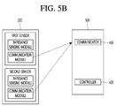
- Fig. 5b is a diagram for explanation of an example in which a monitoring sensor unit and a server communicate with each other directly without a procedure in which a controller calculates power loss.
- each sensor of a monitoring sensor unit 200 may include not just an impedance sensing module, but also a communication module.
- each sensor of the monitoring sensor unit 200 may communicate directly with a server 500. Specifically, using the communication modules, the monitoring sensor unit 200 may transmit, to the server 500, at least one of the following: a voltage value each element, a current value, temperature, frequency, impedance value, and amount of variation in impedance in each element.
- the server 500 may receive data from the monitoring sensor unit 200 through a communicator 410. Based on the received data, a controller 420 of the server 500 may calculate amount of power loss in each element, amount of variation in power loss in each element, amount of power loss in a harmonic filter, amount of variation in power loss in a harmonic filter.
- the server 500 may include a display (not shown), and the server 500 may output, through the display (not shown), at least one of the following: a voltage value of each element, a current value of each element, temperature of each element, an impedance value of each element, amount of variation in impedance of each element, power loss in each element, amount of variation in power loss in each element, power loss in a harmonic filter, variation in power loss in the harmonic filter.
- the power loss measuring system does not measure an entire power loss in a harmonic filter, but measure power loss in each element of the harmonic filter, so that it enables accurate monitoring of the power loss and reflect the monitoring result in designing a configuration and specifications of the harmonic filter
- the power loss measuring system is able to precisely measure power loss relative to variation in impedance according to an applied voltage, current, temperature, and frequency.
- the power loss measuring system measures amount of power loss by measuring amount of variation in impedance of each element, and thus it is easy to measure amount of power loss than the case where a power is measured by measuring a voltage value and a current value of each element.
- controller 300 is a configuration generally in charge of controlling a device, and may be the same as a Central Processing Unit (CPU), a microprocessor, and a processor.
- CPU Central Processing Unit
- microprocessor a microprocessor
- processor a processor
- the methods and/or operations described above may be recorded, stored, or fixed in one or more computer-readable storage media that includes program instructions to be implemented by a computer to cause a processor to execute or perform the program instructions.
- the media may also include, alone or in combination with the program instructions, data files, data structures, and the like.
- Examples of computer-readable storage media include Hard Disk Drive (HDD), Solid State Disk (SSD), Silicon Disk Drive (SDD), read-only memory (ROM), random access memory (RAM), CD-ROM, magnetic tape, floppy disks, optical data storage device, and a carrier wave (e.g., transmission on the Internet).
- the computer may include a controller 180 of a terminal. Therefore, the above descriptions should not be understood in a limited range, but they should be considered examples. The scope of the disclosure should be determined by reasonable interpretation of the following claims, and the disclosure is to cover all modifications, equivalents, and alternatives falling within the spirit and scope of the invention as defined by the claims.
Landscapes
- Engineering & Computer Science (AREA)
- Power Engineering (AREA)
- Physics & Mathematics (AREA)
- General Physics & Mathematics (AREA)
- Remote Monitoring And Control Of Power-Distribution Networks (AREA)
- Supply And Distribution Of Alternating Current (AREA)
Abstract
Description
- The present disclosure relates to power loss measuring system for measuring power loss in a harmonic filter using variation in impedance of each element included in the harmonic filter, and a power losing measuring method thereof.
- High Voltage Direct Current (HVDC) transmission indicates a power transmission method of converting, by a transmission site, AC power produced at a power station into DC power to transmit the DC power and then re-converting, by a reception site, the DC power into the AC power to supply power. The HVDC transmission may enable efficient and economical power transmission through a voltage increase that is the advantage of AC transmission. In addition, the HVDC transmission may overcome many limitations of the Ac transmission.
- In such HVDC transmission, it is essential to convert AC power into DC power and then the DC power into Ac power. However, harmonics occur due to characteristics of a switch and a load during the conversion, and therefore, a harmonic filter is generally used to prevent harmful effects of the harmonics.
- A general configuration of the harmonic filter is as shown in
Fig. 1 . - Referring to
Fig. 1 , the harmonic filter includes at least one inductor, at least one capacitor, and at least one resistor. - Conventionally, to measure power loss occurring at a harmonic filter, a voltage and a current are measured in a Gas Insulated Switchgear (GIS) 10 disposed in a receiver of the harmonic filter. That is, the power loss occurring at the harmonic filter is conventionally calculated using voltage and current values measured by the receiver of the harmonic filter.
- However, an existing system for measuring power loss in a harmonic filter aims mainly to measure voltage and current, rather than the power loss itself. In addition, it is hard to measure power loss according to a real-time change in temperature and frequency because variation in impedance according to a change in temperature and frequency is not known. Further, power loss of each element cannot be measured, and variation in impedance according to a change in a voltage and a current is not known, so that they cannot be reflected in the system design.
- The present disclosure is provided to solve the aforementioned drawbacks, and relates to power loss measuring system, which measures a loss in a harmonic filter based on variation in impedance of each element of the harmonic element, and power loss measuring method thereof.
- According to one embodiment of the present disclosure, there is provided a power loss measuring system for measuring power loss in a harmonic filter included in a High Voltage Direct Current (HVDC) transmission system, the power loss measuring system including: the harmonic filter including a plurality of elements; a monitoring sensor unit sensing variation in impedance of the plurality of elements; and a controller obtaining power loss in the harmonic filter using amount of variation in impedance of the plurality of elements.
- The plurality of elements may include at least one resistor, at least one capacitor, and at least one inductor; the monitoring sensor unit may sense variation in impedance of each of the at least one resistor, the at least one capacitor, and the at least one inductor; and the controller may obtain power loss occurring in each of the at least one resistor, the at least one capacitor, and the at least one inductor based on the amount of variation in impedance of each of the at least one resistor, the at least one capacitor, and the at least one inductor.
- The monitoring sensor unit may obtain the amount of variation in impedance using an impedance value, which is sensed by the monitoring sensor unit, and an initial impedance value of each of the at least one resistor, the at least one capacitor, and the at least one inductor.
- Impedance of the plurality of elements may be changed due to at least one of a change in temperature and a change in frequency of the plurality of elements.
- The controller may obtain the power loss in the harmonic filter using variation in impedance of each of the plurality of elements and at least one of a rated voltage and a rated current of each of the plurality of elements.
- The rated voltage of each of the plurality of elements may be a fixed value.
- The controller may include a communication module communicating with a server, calculate at least one of amount of the power loss in each of the plurality of elements and amount of the power loss in the harmonic filter based on the amount of variation in impedance of each of the plurality of elements, and transmit the at least one of the amount of the power loss in each of the plurality of elements and the power loss in the harmonic filter via the communication module to the server.
- The monitoring sensor unit may comprise a communication module communicating with a server and transmit the amount of variation in impedance of each of the plurality of elements via the communication module to the server.
- The power loss measuring system may further include a storage, wherein the controller stores, in the storage, at least one of an initial impedance value of each of the plurality of elements, amount of variation in impedance of each of the plurality of elements, amount of power loss occurring in each of the plurality of elements, and amount of power loss occurring in the harmonic filter.
- The monitoring sensor unit may sense an impedance value of each of the plurality of elements and transmit the sensed impedance value of each of the plurality of elements to the controller, and the controller may calculate amount of variation in impedance of each of the plurality of elements based on the received impedance value of each of the plurality of elements.
- According to another aspect of the present disclosure, there is provided a power loss measuring method of power loss measuring system for measuring power loss in a harmonic filter included in a High Voltage Direct Current (HVDC) transmission system, the power loss measuring method including: sensing impedance values of a plurality of elements included in the harmonic filter; obtaining variation in impedance of the plurality of elements; and obtaining power loss in the harmonic filter using amount of variation in impedance of the plurality of elements.
- The plurality of elements may include at least one resistor, at least one capacitor, and at least one inductor; the obtaining of variation in impedance of the plurality of elements may include calculating variation in impedance of each of the at least one resistor, the at least one capacitor, and the at least one inductor; and the obtaining of power loss in the harmonic filter may include calculating power loss occurring in each of the at least one resistor, the at least one capacitor, and the at least one inductor based on the amount of variation in impedance of each of the at least one resistor, the at least one capacitor, and the at least one inductor.
-
-
Fig. 1 is a diagram illustrating a method for measuring power loss in an existing harmonic filter. -
Fig. 2 is a block diagram illustrating a configuration of power loss measuring system according to an embodiment of the present disclosure. -
Fig. 3 is a flowchart illustrating power loss measuring method of power loss measuring system according to an embodiment of the present disclosure. -
Fig. 4 is a diagram for explanation of a method for measuring power loss in each element included in a harmonic filter according to an embodiment of the present disclosure. -
Fig. 5A and B is a diagram for explanation of a method for transmitting data to a server according to an embodiment of the present disclosure. - The present invention will now be described more fully with reference to the accompanying drawings, in which exemplary embodiments of the invention are shown. Like reference numerals in the drawings, even in different drawings, denote like elements. Throughout the drawings and the detailed description, unless otherwise described, the same drawing reference numerals are understood to refer to the same elements, features, and structures. In the following, the terms "module" and "unit" are used for convenience of descriptions, not for distinction or difference of elements. Hereinafter, in describing the present invention, detailed descriptions of relevant functions or structures well-known to those skilled in the art will be omitted when it is considered that the descriptions obscure the point of the present invention. The invention is described more fully hereinafter with reference to the accompanying drawings, in which exemplary embodiments of the invention are shown. This invention may, however, be embodied in many different forms and should not be construed as limited to the embodiments set forth herein. It should be understood, however, that there is no intent to limit the invention to the particular forms disclosed, but on the contrary, the invention is to cover all modifications, equivalents, and alternatives falling within the spirit and scope of the invention as defined by the claims.
-
Fig. 2 is a block diagram illustrating a loss power measuring system according to an embodiment of the present disclosure. - Referring to
Fig. 2 , powerloss measuring system 10 according to the present disclosure may include aharmonic filter 100, amonitoring sensor 200, acontroller 300, andstorage 400. - The
harmonic filter 100 may remove harmonics occurring in a High Voltage Direct Current (HVDC) system. Specifically, in a HVDC transmission method, a thyristor converter is used to convert AC power into DC power, and harmonics occur during the conversion due to characteristics of the thyristor converter that controls a phase. In addition, theharmonic filter 100 may remove the harmonics that occur during the conversion. - The
harmonic filter 100 may include a plurality of elements. Specifically, theharmonic filter 100 may include a capacitive element, an inductive element, and a resistor, and may remove n-th harmonics that occur when AC power is rectified. - A capacitor may be used as the capacitive element, and an inductor may be used as the inductive element.
- The
harmonic filter 100 installed in a transceiver of the HVDC system may remove harmonics occurring when AC power is converted into DC power. In addition, theharmonic filter 100 installed in a receiver of the HVDC system may remove harmonics occurring when DC power is converted into AC power. Furthermore, theharmonic filter 100 may improve a power factor by supplying reactive power to the HVDC system. - The
monitoring sensor unit 200 may sense variation in impedance of a plurality of devices. Specifically, themonitoring sensor unit 200 may include a plurality of monitoring sensors which correspond to the number of a capacitive element(s), an inductive element(s), and a resistor(s) included in theharmonic filter 100, and may sense an impedance value of each of the capacitive element(s), the inductive element(s), and the resistor(s) included in theharmonic filter 100. In addition, the plurality of monitoring sensors obtain amount of variation in impedance using the sensed impedance value, and transmit the obtained amount of variation in impedance to thecontroller 300. In this case, each monitoring sensor may calculate the amount of variation in impedance based on the initial impedance value that each capacitive element, inductive element, and resistor has in a specific condition. - Each monitoring sensor may include a sensing module for sensing impedance of an element, a calculation module for calculating amount of variation in impedance of an element, a communication module for transmitting the calculated amount of variation in impedance to the
controller 300. - Meanwhile, each of the plurality monitoring sensor included in the
monitoring sensor unit 200 calculates amount of variation in impedance in the above-described embodiment, but aspects of the present disclosure are not limited thereto. Specifically, each of the plurality of monitoring sensors may consist of a sensing component for sensing impedance value of an element and a communicating component for transmitting the sensed impedance value to thecontroller 300, and amount of variation in impedance may be calculated by thecontroller 300. - The
controller 300 may measure amount of variation in impedance of a plurality of elements. Specifically, when receiving information on an impedance value of each of the plurality of elements from themonitoring sensor unit 200, thecontroller 300 may calculate amount of variation in impedance using the received information. More specifically, thecontroller 300 stores, in thestorage 400, an initial impedance value that each capacitive element, inductive element, or resistor has in a specific condition. Then, thecontroller 300 compares a receive impedance value with a stored initial impedance value to calculate amount of variation in impedance of each element. - In addition, based on amount of variation in impedance of each element, the
controller 300 may calculate power loss occurring at theharmonic filter 300. Specifically, by calculating variation in power loss occurring in each element based on calculated amount of variation in impedance of each element included in theharmonic filter 100, thecontroller 300 may calculate amount of variation in power loss occurring in theharmonic filter 100. In addition, by calculating amount of variation in power loss occurring in each element based on received variation in impedance of each element from themonitoring sensor unit 200, thecontroller 300 may calculate the amount of variation in the entire power loss occurring in theharmonic filter 100. - The
storage 400 is under control of thecontroller 300 and may store at least one of the following: an initial impedance value of each element included in theharmonic filter 100, amount of variation in impedance, amount of power loss occurring in each element, and amount of an entire power loss occurring in theharmonic filter 100. -
Fig. 3 is a flowchart illustrating power loss measuring method of power loss measuring system according to an embodiment of the present disclosure. - Referring to
Fig. 3 , power loss measuring method of power loss measuring system according to an embodiment of the present disclosure may include measuring impedance of a plurality of elements (s310), calculating power loss in a harmonic filter based on amount of variation in impedance of the plurality of elements (S330), and storing data (S350). - Measuring impedance of the plurality of elements in
step 310 is described in detail with reference toFig. 4 . -
Fig. 4 is a diagram for explanation of a method for measuring power loss in each of a plurality of elements included in a harmonic filter according to an embodiment of the present disclosure. - Referring to
Fig. 4 , aharmonic filter 100 may include a plurality of elements. Specifically, as shown inFig. 4 , theharmonic filter 100 may include a plurality of capacitors C1, C2, and C3, a plurality of inductors L1, L2, and L3, and a plurality of resistors R1, R2, and R3, and may remove harmonics equal to higher than a reference level by using a combination of the capacitors, inductors, and resistors. Meanwhile,Fig. 4 shows a harmonic filter including three capacitors, three inductors, and three resistors, but aspects of the present disclosure are not limited thereto. That is, a harmonic filter of the present disclosure may be any filter which is able to remove harmonics by using various combinations of at least one capacitor, at least one inductor, and at least one resistor. - Meanwhile, the plurality of capacitors C1, C2, and C3, the plurality of inductors L1, L2, and L3, and the plurality of resistors R1, R2, and R3 have impedance values, respectively, and the impedance values are able to be changed. Specifically, the impedance values may be changed according to a voltage or a current frequency. In addition, if there is a change in temperature, an impedance value may be changed according to characteristics of an element.
- Meanwhile, power loss in each element may be calculated using a change in frequency and temperature, a voltage value, and a current value. However, these values are often changed so accurate measurements thereof are hard to obtain. However, as proposed in the present disclosure, if amount of variation in impedance of each element where power loss occurs, it is possible to calculate the power loss.
- A plurality of
sensors monitoring sensor unit 200 may measure impedance of a plurality of capacitors C1, C2, and C3, impedance of a plurality of inductors L1, L2, and L3, and a plurality of resistors R1, R2, and R3, respectively. In addition, the plurality ofsensors controller 300 may be enabled to monitor a voltage and a current of each element based on a combination thereof and improve accuracy in calculation of power loss. However, in power loss measuring method proposed in the present disclosure, it is possible to measure power loss in each element based solely on a change in an impedance value, and thus, it is not essential to measure a voltage and a current. - The amount of variation in impedance may be a difference between an initial impedance value and a current impedance value of an element. Specifically, the plurality of
sensors sensors - Meanwhile, without storing the initial impedance values for calculation of variation in impedance, the plurality of
sensors controller 300. In this case, thecontroller 300 may calculate amount of variation in impedance. Alternatively, the impedance values measured by the plurality of elements may be used to calculate power loss in each element without calculating amount of variation in impedance by thecontroller 300. - Each of the plurality of
sensors sensors - Using variation in impedance of the plurality of elements, the
controller 300 may calculate power loss in a harmonic filter. Specifically, using each element's amount of variation in impedance transmitted from the plurality ofsensors controller 300 may calculate amount of variation in power loss in each element. The amount of power loss in each element may be calculated as the following formula:
- The current value I in each element is a fixed value according to a rated current of the system. Thus, using the fixed current value I and the value of variation of impedance ΔZ, it is possible to measure variation in power loss in an element.
- That is, the
controller 300 may calculate variation in amount of power loss ΔW in each of the plurality of elements (the capacitors C1, C2, and C3, the inductors L1, L2, and L3, and the resistors R1, R2, and R3) by using amount of variation in impedance and a rated current value of each of the plurality of the elements (the capacitors C1, C2, and C3, the inductors L1, L2, and L3, and the resistors R1, R2, and R3). - In addition, the voltage value v of each element is a fixed value according to a rated voltage of the system. Thus, the current value I may be calculated using the fixed voltage value v and an impedance value in each element, and amount of variation in power loss ΔW in each element may be calculated using the current value I and the amount of variation in impedance ΔZ.
- In addition, variation in power loss in each element may be calculated as the following formula:

- The voltage value v in each element is a fixed value according to a rated voltage of the system, and amount of variation in power loss ΔW in each element may be calculated using the fixed voltage value v and the amount of variation in impedance ΔZ.
- In addition, using variation in impedance and a rated voltage of each of the plurality of elements (the capacitors C1, C2, and C3, the inductors L1, L2, and L3, and the resistors R1, R2, and R3), the
controller 300 may calculate amount of variation in power loss ΔW in each element. - In addition, using the variation in power loss ΔW in each element, the
controller 300 may calculate amount of variation in the entire power loss that occurs in theharmonic filter 100. - Meanwhile, in this embodiment, amount of variation in power loss ΔW are calculated using amount of variation in impedance ΔZ, so the amount of variation in power loss ΔW calculated in this embodiment may be an amount of power loss that is changed from amount of power loss which occurs in a basic condition (basic frequency, basic temperature, basic voltage, and basic current).
- Meanwhile, this embodiments is a case where the
controller 300 calculate amount of variation in power loss in each element based on amount of variation in impedance in each element, which is received from each of the plurality ofsensors sensors controller 300, and then thecontroller 300 may calculate amount of variation in impedance of each element by using an initial impedance value of each element, which is stored in thestorage 400, and may calculate amount of variation in power loss in each element by using the calculated amount of variation in impedance and a rated voltage of each element. - Meanwhile, based on impedance of each of the plurality of elements, the
controller 300 may calculate power loss in a harmonic filter. Specifically, based on impedance value of each of the plurality of elements, which are transmitted from the plurality ofsensors controller 300 may calculate amount of power loss in each of the plurality of elements. The amount of power loss in each element may be calculated as the following formula:
- In addition, the power loss in each element may be calculated as the following formula:

- The calculated power loss W may be strengthened amount of power loss. Specifically, the power loss W is calculated using the magnitude of impedance |Z| in this embodiment, so the power loss W may be an absolute value of power loss occurring in each of the plurality of elements.
- In addition, using the amount of power loss in each element, the
controller 300 may calculate power loss occurring in the entireharmonic filter 100. - Meanwhile, the
controller 300 may store calculated data in thestorage 400. Specifically, thecontroller 300 may store, in thestorage 400, at least one of the following: a voltage value of each element, a current value of each element, temperature of each element, a frequency of each element, an impedance value of each element, amount of variation in impedance of each element, amount of power loss in each element, and amount of variation in power loss in each element, wherein the aforementioned data items are transmitted from themonitoring sensor unit 200. In addition, thecontroller 300 may store, in thestorage 400, time information which includes at least one measurement of the following: a voltage value of each element, a current value of each element, temperature of each element, a frequency of each element, an impedance value of each element, amount of variation in impedance of each element, amount of power loss in each element, and variation in power loss in each element. In addition, the stored data may be used to monitor the plurality of elements and design the system. -
Fig. 5 is a diagram for explanation of a method of transmitting data to a server according to an embodiment of the present disclosure. - Referring to
Fig. 5A , through an embedded communication module, acontroller 300 may transmit, to aserver 500, at least one of the following: a voltage value of each element, a current value of each element, temperature of each element, a frequency of each element, an impedance value of each element, amount of variation in impedance of each element, amount of power loss in each element, and amount of variation in power loss in each element, wherein the voltage value, current value, temperature, frequency, impedance value, and amount of variation in impedance are transmitted from a plurality of elements included in amonitoring sensor unit 200, and the amount of power loss in each element and the amount of variation in power loss in each element are calculated by power loss calculation module. Here, theserver 500 may be a server of a company providing power in an HVDC system or a server of an operator managing provided power via the HVDC system. Such an operator or company may monitor power loss occurring in each element of a harmonic filter based on information received from thecontroller 300. -
Fig. 5b is a diagram for explanation of an example in which a monitoring sensor unit and a server communicate with each other directly without a procedure in which a controller calculates power loss. - Referring to
Fig. 5b , each sensor of amonitoring sensor unit 200 may include not just an impedance sensing module, but also a communication module. In addition, each sensor of themonitoring sensor unit 200 may communicate directly with aserver 500. Specifically, using the communication modules, themonitoring sensor unit 200 may transmit, to theserver 500, at least one of the following: a voltage value each element, a current value, temperature, frequency, impedance value, and amount of variation in impedance in each element. - The
server 500 may receive data from themonitoring sensor unit 200 through acommunicator 410. Based on the received data, acontroller 420 of theserver 500 may calculate amount of power loss in each element, amount of variation in power loss in each element, amount of power loss in a harmonic filter, amount of variation in power loss in a harmonic filter. - Meanwhile, the
server 500 may include a display (not shown), and theserver 500 may output, through the display (not shown), at least one of the following: a voltage value of each element, a current value of each element, temperature of each element, an impedance value of each element, amount of variation in impedance of each element, power loss in each element, amount of variation in power loss in each element, power loss in a harmonic filter, variation in power loss in the harmonic filter. - As described above, the power loss measuring system according to an embodiment of the present disclosure does not measure an entire power loss in a harmonic filter, but measure power loss in each element of the harmonic filter, so that it enables accurate monitoring of the power loss and reflect the monitoring result in designing a configuration and specifications of the harmonic filter
- In addition, the power loss measuring system according to an embodiment of the present disclosure is able to precisely measure power loss relative to variation in impedance according to an applied voltage, current, temperature, and frequency.
- In addition, the power loss measuring system according to an embodiment of the present disclosure measures amount of power loss by measuring amount of variation in impedance of each element, and thus it is easy to measure amount of power loss than the case where a power is measured by measuring a voltage value and a current value of each element.
- Meanwhile, the
controller 300 is a configuration generally in charge of controlling a device, and may be the same as a Central Processing Unit (CPU), a microprocessor, and a processor. - The methods and/or operations described above may be recorded, stored, or fixed in one or more computer-readable storage media that includes program instructions to be implemented by a computer to cause a processor to execute or perform the program instructions. The media may also include, alone or in combination with the program instructions, data files, data structures, and the like. Examples of computer-readable storage media include Hard Disk Drive (HDD), Solid State Disk (SSD), Silicon Disk Drive (SDD), read-only memory (ROM), random access memory (RAM), CD-ROM, magnetic tape, floppy disks, optical data storage device, and a carrier wave (e.g., transmission on the Internet). In addition, the computer may include a controller 180 of a terminal. Therefore, the above descriptions should not be understood in a limited range, but they should be considered examples. The scope of the disclosure should be determined by reasonable interpretation of the following claims, and the disclosure is to cover all modifications, equivalents, and alternatives falling within the spirit and scope of the invention as defined by the claims.
Claims (15)
- A power loss measuring system (10) for measuring power loss in a harmonic filter (100) included in a High Voltage Direct Current (HVDC) transmission system, the power loss measuring system comprising:the harmonic filter (100) including a plurality of elements;a monitoring sensor unit (200) sensing variation in impedance of the plurality of elements; anda controller (300) obtaining power loss in the harmonic filter (100) using amount of variation in impedance of the plurality of elements.
- The power loss measuring system of claim 1, wherein:the plurality of elements comprises at least one resistor, at least one capacitor, and at least one inductor;the monitoring sensor unit (200) senses variation in impedance of each of the at least one resistor, the at least one capacitor, and the at least one inductor; andthe controller (300) obtains power loss occurring in each of the at least one resistor, the at least one capacitor, and the at least one inductor based on the amount of variation in impedance of each of the at least one resistor, the at least one capacitor, and the at least one inductor.
- The power loss measuring system of claim 2, wherein the monitoring sensor unit (200) obtains the amount of variation in impedance using an impedance value, which is sensed by the monitoring sensor unit (200), and an initial impedance value of each of the at least one resistor, the at least one capacitor, and the at least one inductor.
- The power loss measuring system of any one of claims 1 to 3, wherein the impedance of the plurality of elements is changed by at least one of a change in temperature and a change in frequency of the plurality of elements.
- The power loss measuring system of any one of claims 1 to 4, wherein the controller (300) obtains the power loss in the harmonic filter using variation in impedance of each of the plurality of elements and at least one of a rated voltage and a rated current of each of the plurality of elements.
- The power loss measuring system of claim 5, wherein the rated voltage of each of the plurality of elements is a fixed value.
- The power loss measuring system of any one of claims 1 to 6, wherein the controller (300) comprises a communication module communicating with a server (500), calculates at least one of amount of the power loss in each of the plurality of elements and amount of the power loss in the harmonic filter (100) based on the amount of variation in impedance of each of the plurality of elements, and transmits the at least one of the amount of the power loss in each of the plurality of elements and the amount of the power loss in the harmonic filter (100) via the communication module to the server (500).
- The power loss measuring system of any one of claims 1 to 7, wherein the monitoring sensor unit (200) comprises a communication module communicating with a server (500) and transmits the amount of variation in impedance of each of the plurality of elements via the communication module to the server (500).
- The power loss measuring system of any one of claims 1 to 8, further comprising a storage (400),
wherein the controller stores, in the storage (400), at least one of an initial impedance value of each of the plurality of elements, amount of variation in impedance of each of the plurality of elements, amount of power loss occurring in each of the plurality of elements, and amount of power loss occurring in the harmonic filter. - The power loss measuring system of claim 1,
wherein the monitoring sensor unit (200) senses an impedance value of each of the plurality of elements and transmits the sensed impedance value of each of the plurality of elements to the controller (300), and
wherein the controller (300) calculates amount of variation in impedance of each of the plurality of elements based on the received impedance value of each of the plurality of elements. - A power loss measuring method of power loss measuring system for measuring power loss in a harmonic filter (100) included in a High Voltage Direct Current (HVDC) transmission system, the power loss measuring method comprising:sensing impedance values of a plurality of elements included in the harmonic filter (100);obtaining variation in impedance of the plurality of elements; andobtaining power loss in the harmonic filter (100) using amount of variation in impedance of the plurality of elements.
- The power loss measuring method of claim 11, wherein:the plurality of elements comprises at least one resistor, at least one capacitor, and at least one inductor;the obtaining of variation in impedance of the plurality of elements comprises calculating variation in impedance of each of the at least one resistor, the at least one capacitor, and the at least one inductor; andthe obtaining of power loss in the harmonic filter (100) comprises calculating power loss occurring in each of the at least one resistor, the at least one capacitor, and the at least one inductor based on the amount of variation in impedance of each of the at least one resistor, the at least one capacitor, and the at least one inductor.
- The power loss measuring method of claim 12, wherein the obtaining of variation in impedance of the plurality of elements comprises calculating the amount of variation in impedance based on an initial impedance value and a sensed impedance value of each of the at least one resistor, the at least one capacitor, and the at least one inductor.
- The power loss measuring method of any one of claims 11 to 13, wherein the impedance of the plurality of elements is changed by at least one of a change in temperature and a change in frequency of the plurality of elements.
- The power loss measuring method of any one of claims 11 to 14, wherein the obtaining of power loss in the harmonic filter (100) comprises obtaining the power loss in the harmonic filter based on variation in impedance of each of the plurality of elements and at least one of a rated voltage and a rated current of each of the plurality of elements.
Applications Claiming Priority (1)
| Application Number | Priority Date | Filing Date | Title |
|---|---|---|---|
| KR1020150108401A KR102027558B1 (en) | 2015-07-30 | 2015-07-30 | Power loss measuring system for measuring power loss at harmonic filter included in high voltage direct current(hvdc) ststem and method for measuring power loss thereof |
Publications (2)
| Publication Number | Publication Date |
|---|---|
| EP3125396A1 true EP3125396A1 (en) | 2017-02-01 |
| EP3125396B1 EP3125396B1 (en) | 2020-03-25 |
Family
ID=55697038
Family Applications (1)
| Application Number | Title | Priority Date | Filing Date |
|---|---|---|---|
| EP16163648.5A Active EP3125396B1 (en) | 2015-07-30 | 2016-04-04 | Power loss measuring system for measuring power loss at harmonic filter included in high voltage direct current (hvdc) transmission system, and power loss measuring method thereof |
Country Status (6)
| Country | Link |
|---|---|
| US (1) | US10345393B2 (en) |
| EP (1) | EP3125396B1 (en) |
| JP (1) | JP6284986B2 (en) |
| KR (1) | KR102027558B1 (en) |
| CN (1) | CN106405217B (en) |
| ES (1) | ES2797099T3 (en) |
Cited By (1)
| Publication number | Priority date | Publication date | Assignee | Title |
|---|---|---|---|---|
| CN109347106A (en) * | 2018-11-07 | 2019-02-15 | 国家电网有限公司 | A method and system for evaluating AC filter loss |
Families Citing this family (4)
| Publication number | Priority date | Publication date | Assignee | Title |
|---|---|---|---|---|
| KR102404595B1 (en) * | 2017-06-30 | 2022-06-07 | 한국전력공사 | Apparatus for detecting error of HVDC AC filter |
| US10644756B2 (en) * | 2018-07-30 | 2020-05-05 | Nxp B.V. | Transmitter calibration for NFC (near field communication) device |
| CN109768565B (en) * | 2019-02-27 | 2020-07-10 | 南方电网科学研究院有限责任公司 | Passive impedance adapter parameter design method and device suitable for flexible direct current |
| US11585836B2 (en) * | 2020-03-20 | 2023-02-21 | InductEV, Inc. | Current sensing in a wireless power transfer system |
Citations (4)
| Publication number | Priority date | Publication date | Assignee | Title |
|---|---|---|---|---|
| WO1997049167A1 (en) * | 1996-06-17 | 1997-12-24 | Asea Brown Boveri Ab | Filter equipment |
| WO1997049168A1 (en) * | 1996-06-21 | 1997-12-24 | Wisconsin Alumni Research Foundation | Power line harmonic reduction by hybrid parallel active/passive filter system with square wave inverter and dc bus control |
| DE19838111A1 (en) * | 1998-08-21 | 2000-03-02 | Siemens Ag | Monitoring method for DC-link filter in HVDC power transmission installation |
| WO2012000510A1 (en) * | 2010-06-29 | 2012-01-05 | Vestas Wind Systems A/S | Method and system for monitoring structural health of a filter in a wind turbine, and a wind turbine |
Family Cites Families (14)
| Publication number | Priority date | Publication date | Assignee | Title |
|---|---|---|---|---|
| JP2889667B2 (en) | 1990-07-26 | 1999-05-10 | 日新電機 株式会社 | AC filter overload detection device |
| JPH1155857A (en) | 1997-07-29 | 1999-02-26 | Toshiba Corp | Harmonic filter |
| US7593380B1 (en) | 1999-03-05 | 2009-09-22 | Ipr Licensing, Inc. | Variable rate forward error correction for enabling high performance communication |
| TW535081B (en) | 2000-12-20 | 2003-06-01 | Ibm | Method and system of fulfilling requests for information from a network client |
| US6907460B2 (en) | 2001-01-18 | 2005-06-14 | Koninklijke Philips Electronics N.V. | Method for efficient retransmission timeout estimation in NACK-based protocols |
| US7792121B2 (en) | 2003-01-03 | 2010-09-07 | Microsoft Corporation | Frame protocol and scheduling system |
| CN100403036C (en) | 2006-03-10 | 2008-07-16 | 中国航天科技集团公司第五研究院第五一四研究所 | A method of measuring electric power and its measuring device |
| KR100666509B1 (en) | 2006-08-03 | 2007-01-09 | (주) 피에스디테크 | Harmonic filter with ON / OFF switching function |
| KR100883502B1 (en) | 2008-09-02 | 2009-02-16 | 이성고 | Automatic harmonic control device |
| JP2012105523A (en) | 2010-10-15 | 2012-05-31 | Sony Corp | Communication device, power distribution control device and power distribution control system |
| CN102074951B (en) | 2011-01-24 | 2012-12-26 | 浙江大学 | Design method for direct current (DC) filter in high voltage DC transmission project |
| KR101149906B1 (en) | 2012-02-20 | 2012-06-12 | 백용호 | Harmonics Reduction Apparatus for decreasing a Harmonic Current |
| KR101425400B1 (en) | 2013-08-29 | 2014-08-13 | 한국전력공사 | Power converter for high voltage direct current transmission |
| CN104698265A (en) | 2015-03-27 | 2015-06-10 | 国家电网公司 | High-voltage direct current transmission line corona loss measurement system |
-
2015
- 2015-07-30 KR KR1020150108401A patent/KR102027558B1/en not_active Expired - Fee Related
-
2016
- 2016-04-04 EP EP16163648.5A patent/EP3125396B1/en active Active
- 2016-04-04 ES ES16163648T patent/ES2797099T3/en active Active
- 2016-07-19 US US15/214,190 patent/US10345393B2/en not_active Expired - Fee Related
- 2016-07-21 JP JP2016143157A patent/JP6284986B2/en not_active Expired - Fee Related
- 2016-07-29 CN CN201610618995.7A patent/CN106405217B/en not_active Expired - Fee Related
Patent Citations (4)
| Publication number | Priority date | Publication date | Assignee | Title |
|---|---|---|---|---|
| WO1997049167A1 (en) * | 1996-06-17 | 1997-12-24 | Asea Brown Boveri Ab | Filter equipment |
| WO1997049168A1 (en) * | 1996-06-21 | 1997-12-24 | Wisconsin Alumni Research Foundation | Power line harmonic reduction by hybrid parallel active/passive filter system with square wave inverter and dc bus control |
| DE19838111A1 (en) * | 1998-08-21 | 2000-03-02 | Siemens Ag | Monitoring method for DC-link filter in HVDC power transmission installation |
| WO2012000510A1 (en) * | 2010-06-29 | 2012-01-05 | Vestas Wind Systems A/S | Method and system for monitoring structural health of a filter in a wind turbine, and a wind turbine |
Non-Patent Citations (2)
| Title |
|---|
| TAFFESE ABEL A ET AL: "Modular Multilevel Converter with tuned filter: Operational possibility and simple control", 2014 IEEE 15TH WORKSHOP ON CONTROL AND MODELING FOR POWER ELECTRONICS (COMPEL), IEEE, 22 June 2014 (2014-06-22), pages 1 - 6, XP032628756, DOI: 10.1109/COMPEL.2014.6877214 * |
| YONG LI ET AL: "Simulation of the Electromagnetic Response Characteristic of an Inductively Filtered HVDC Converter Transformer Using Field-Circuit Coupling", IEEE TRANSACTIONS ON INDUSTRIAL ELECTRONICS, IEEE SERVICE CENTER, PISCATAWAY, NJ, USA, vol. 59, no. 11, 1 November 2012 (2012-11-01), pages 4020 - 4031, XP011448875, ISSN: 0278-0046, DOI: 10.1109/TIE.2011.2175673 * |
Cited By (2)
| Publication number | Priority date | Publication date | Assignee | Title |
|---|---|---|---|---|
| CN109347106A (en) * | 2018-11-07 | 2019-02-15 | 国家电网有限公司 | A method and system for evaluating AC filter loss |
| CN109347106B (en) * | 2018-11-07 | 2022-02-01 | 国家电网有限公司 | Method and system for evaluating loss of alternating current filter |
Also Published As
| Publication number | Publication date |
|---|---|
| US10345393B2 (en) | 2019-07-09 |
| KR102027558B1 (en) | 2019-10-01 |
| CN106405217B (en) | 2019-04-30 |
| KR20170014671A (en) | 2017-02-08 |
| CN106405217A (en) | 2017-02-15 |
| EP3125396B1 (en) | 2020-03-25 |
| ES2797099T3 (en) | 2020-12-01 |
| JP2017034981A (en) | 2017-02-09 |
| US20170030978A1 (en) | 2017-02-02 |
| JP6284986B2 (en) | 2018-02-28 |
Similar Documents
| Publication | Publication Date | Title |
|---|---|---|
| EP3125396B1 (en) | Power loss measuring system for measuring power loss at harmonic filter included in high voltage direct current (hvdc) transmission system, and power loss measuring method thereof | |
| RU2464581C2 (en) | Measurement of full resistance of power transmission line | |
| KR101928904B1 (en) | A method of calibrating a parasitic metal detection system and a method of collecting calibration data for a parasitic metal detection system | |
| EP3242371B1 (en) | Apparatus for predicting power loss of transformer | |
| US20190229561A1 (en) | Foreign object detection in inductive power transfer field | |
| EP2905871A1 (en) | Control device, power transmission device, power reception device, and control method | |
| US20210135506A1 (en) | Detecting foreign objects in wireless power transfer systems | |
| US8446157B2 (en) | Capacitance meter, method, computer program and computer program product for improved capacitance measurement | |
| JP6034437B2 (en) | Damage measurement system for HVDC | |
| CN113381516A (en) | Wireless charging foreign matter detection method and device | |
| KR20200063197A (en) | Q factor measurement | |
| US20220416588A1 (en) | Wireless charging method, device and system | |
| US20170031050A1 (en) | Distance determination based on reflected admittance | |
| WO2015004447A1 (en) | Method of determining a condition of an electrical power network and apparatus therefor | |
| FI113592B (en) | Procedure for adjusting a compensation choke in an electricity distribution network | |
| US11175322B2 (en) | Gating energy consumption accumulation by detecting a fundamental component of a current | |
| EP3285382B1 (en) | Detection methods | |
| JP3891434B2 (en) | Judgment method of electric quantity change factor | |
| US20230176094A1 (en) | Alternating-current energy detection apparatus | |
| US12413104B1 (en) | Power loss accounting method for in-power foreign object detection |
Legal Events
| Date | Code | Title | Description |
|---|---|---|---|
| PUAI | Public reference made under article 153(3) epc to a published international application that has entered the european phase |
Free format text: ORIGINAL CODE: 0009012 |
|
| STAA | Information on the status of an ep patent application or granted ep patent |
Free format text: STATUS: THE APPLICATION HAS BEEN PUBLISHED |
|
| AK | Designated contracting states |
Kind code of ref document: A1 Designated state(s): AL AT BE BG CH CY CZ DE DK EE ES FI FR GB GR HR HU IE IS IT LI LT LU LV MC MK MT NL NO PL PT RO RS SE SI SK SM TR |
|
| AX | Request for extension of the european patent |
Extension state: BA ME |
|
| STAA | Information on the status of an ep patent application or granted ep patent |
Free format text: STATUS: REQUEST FOR EXAMINATION WAS MADE |
|
| 17P | Request for examination filed |
Effective date: 20170728 |
|
| RBV | Designated contracting states (corrected) |
Designated state(s): AL AT BE BG CH CY CZ DE DK EE ES FI FR GB GR HR HU IE IS IT LI LT LU LV MC MK MT NL NO PL PT RO RS SE SI SK SM TR |
|
| STAA | Information on the status of an ep patent application or granted ep patent |
Free format text: STATUS: EXAMINATION IS IN PROGRESS |
|
| 17Q | First examination report despatched |
Effective date: 20180726 |
|
| GRAP | Despatch of communication of intention to grant a patent |
Free format text: ORIGINAL CODE: EPIDOSNIGR1 |
|
| STAA | Information on the status of an ep patent application or granted ep patent |
Free format text: STATUS: GRANT OF PATENT IS INTENDED |
|
| INTG | Intention to grant announced |
Effective date: 20191205 |
|
| GRAS | Grant fee paid |
Free format text: ORIGINAL CODE: EPIDOSNIGR3 |
|
| GRAA | (expected) grant |
Free format text: ORIGINAL CODE: 0009210 |
|
| STAA | Information on the status of an ep patent application or granted ep patent |
Free format text: STATUS: THE PATENT HAS BEEN GRANTED |
|
| AK | Designated contracting states |
Kind code of ref document: B1 Designated state(s): AL AT BE BG CH CY CZ DE DK EE ES FI FR GB GR HR HU IE IS IT LI LT LU LV MC MK MT NL NO PL PT RO RS SE SI SK SM TR |
|
| REG | Reference to a national code |
Ref country code: GB Ref legal event code: FG4D |
|
| REG | Reference to a national code |
Ref country code: AT Ref legal event code: REF Ref document number: 1249692 Country of ref document: AT Kind code of ref document: T Effective date: 20200415 Ref country code: IE Ref legal event code: FG4D |
|
| REG | Reference to a national code |
Ref country code: DE Ref legal event code: R096 Ref document number: 602016032381 Country of ref document: DE |
|
| PG25 | Lapsed in a contracting state [announced via postgrant information from national office to epo] |
Ref country code: NO Free format text: LAPSE BECAUSE OF FAILURE TO SUBMIT A TRANSLATION OF THE DESCRIPTION OR TO PAY THE FEE WITHIN THE PRESCRIBED TIME-LIMIT Effective date: 20200625 Ref country code: RS Free format text: LAPSE BECAUSE OF FAILURE TO SUBMIT A TRANSLATION OF THE DESCRIPTION OR TO PAY THE FEE WITHIN THE PRESCRIBED TIME-LIMIT Effective date: 20200325 Ref country code: FI Free format text: LAPSE BECAUSE OF FAILURE TO SUBMIT A TRANSLATION OF THE DESCRIPTION OR TO PAY THE FEE WITHIN THE PRESCRIBED TIME-LIMIT Effective date: 20200325 |
|
| PGFP | Annual fee paid to national office [announced via postgrant information from national office to epo] |
Ref country code: DE Payment date: 20200421 Year of fee payment: 5 Ref country code: ES Payment date: 20200511 Year of fee payment: 5 Ref country code: FR Payment date: 20200423 Year of fee payment: 5 |
|
| PG25 | Lapsed in a contracting state [announced via postgrant information from national office to epo] |
Ref country code: GR Free format text: LAPSE BECAUSE OF FAILURE TO SUBMIT A TRANSLATION OF THE DESCRIPTION OR TO PAY THE FEE WITHIN THE PRESCRIBED TIME-LIMIT Effective date: 20200626 Ref country code: LV Free format text: LAPSE BECAUSE OF FAILURE TO SUBMIT A TRANSLATION OF THE DESCRIPTION OR TO PAY THE FEE WITHIN THE PRESCRIBED TIME-LIMIT Effective date: 20200325 Ref country code: HR Free format text: LAPSE BECAUSE OF FAILURE TO SUBMIT A TRANSLATION OF THE DESCRIPTION OR TO PAY THE FEE WITHIN THE PRESCRIBED TIME-LIMIT Effective date: 20200325 Ref country code: SE Free format text: LAPSE BECAUSE OF FAILURE TO SUBMIT A TRANSLATION OF THE DESCRIPTION OR TO PAY THE FEE WITHIN THE PRESCRIBED TIME-LIMIT Effective date: 20200325 Ref country code: BG Free format text: LAPSE BECAUSE OF FAILURE TO SUBMIT A TRANSLATION OF THE DESCRIPTION OR TO PAY THE FEE WITHIN THE PRESCRIBED TIME-LIMIT Effective date: 20200625 |
|
| PGFP | Annual fee paid to national office [announced via postgrant information from national office to epo] |
Ref country code: IT Payment date: 20200422 Year of fee payment: 5 Ref country code: GB Payment date: 20200423 Year of fee payment: 5 |
|
| REG | Reference to a national code |
Ref country code: NL Ref legal event code: MP Effective date: 20200325 |
|
| REG | Reference to a national code |
Ref country code: LT Ref legal event code: MG4D |
|
| PG25 | Lapsed in a contracting state [announced via postgrant information from national office to epo] |
Ref country code: NL Free format text: LAPSE BECAUSE OF FAILURE TO SUBMIT A TRANSLATION OF THE DESCRIPTION OR TO PAY THE FEE WITHIN THE PRESCRIBED TIME-LIMIT Effective date: 20200325 |
|
| PG25 | Lapsed in a contracting state [announced via postgrant information from national office to epo] |
Ref country code: PT Free format text: LAPSE BECAUSE OF FAILURE TO SUBMIT A TRANSLATION OF THE DESCRIPTION OR TO PAY THE FEE WITHIN THE PRESCRIBED TIME-LIMIT Effective date: 20200818 Ref country code: EE Free format text: LAPSE BECAUSE OF FAILURE TO SUBMIT A TRANSLATION OF THE DESCRIPTION OR TO PAY THE FEE WITHIN THE PRESCRIBED TIME-LIMIT Effective date: 20200325 Ref country code: LT Free format text: LAPSE BECAUSE OF FAILURE TO SUBMIT A TRANSLATION OF THE DESCRIPTION OR TO PAY THE FEE WITHIN THE PRESCRIBED TIME-LIMIT Effective date: 20200325 Ref country code: IS Free format text: LAPSE BECAUSE OF FAILURE TO SUBMIT A TRANSLATION OF THE DESCRIPTION OR TO PAY THE FEE WITHIN THE PRESCRIBED TIME-LIMIT Effective date: 20200725 Ref country code: CZ Free format text: LAPSE BECAUSE OF FAILURE TO SUBMIT A TRANSLATION OF THE DESCRIPTION OR TO PAY THE FEE WITHIN THE PRESCRIBED TIME-LIMIT Effective date: 20200325 Ref country code: RO Free format text: LAPSE BECAUSE OF FAILURE TO SUBMIT A TRANSLATION OF THE DESCRIPTION OR TO PAY THE FEE WITHIN THE PRESCRIBED TIME-LIMIT Effective date: 20200325 Ref country code: SK Free format text: LAPSE BECAUSE OF FAILURE TO SUBMIT A TRANSLATION OF THE DESCRIPTION OR TO PAY THE FEE WITHIN THE PRESCRIBED TIME-LIMIT Effective date: 20200325 Ref country code: SM Free format text: LAPSE BECAUSE OF FAILURE TO SUBMIT A TRANSLATION OF THE DESCRIPTION OR TO PAY THE FEE WITHIN THE PRESCRIBED TIME-LIMIT Effective date: 20200325 |
|
| REG | Reference to a national code |
Ref country code: AT Ref legal event code: MK05 Ref document number: 1249692 Country of ref document: AT Kind code of ref document: T Effective date: 20200325 |
|
| REG | Reference to a national code |
Ref country code: CH Ref legal event code: PL |
|
| REG | Reference to a national code |
Ref country code: ES Ref legal event code: FG2A Ref document number: 2797099 Country of ref document: ES Kind code of ref document: T3 Effective date: 20201201 |
|
| PG25 | Lapsed in a contracting state [announced via postgrant information from national office to epo] |
Ref country code: MC Free format text: LAPSE BECAUSE OF FAILURE TO SUBMIT A TRANSLATION OF THE DESCRIPTION OR TO PAY THE FEE WITHIN THE PRESCRIBED TIME-LIMIT Effective date: 20200325 |
|
| REG | Reference to a national code |
Ref country code: DE Ref legal event code: R097 Ref document number: 602016032381 Country of ref document: DE |
|
| PG25 | Lapsed in a contracting state [announced via postgrant information from national office to epo] |
Ref country code: LU Free format text: LAPSE BECAUSE OF NON-PAYMENT OF DUE FEES Effective date: 20200404 Ref country code: LI Free format text: LAPSE BECAUSE OF NON-PAYMENT OF DUE FEES Effective date: 20200430 Ref country code: AT Free format text: LAPSE BECAUSE OF FAILURE TO SUBMIT A TRANSLATION OF THE DESCRIPTION OR TO PAY THE FEE WITHIN THE PRESCRIBED TIME-LIMIT Effective date: 20200325 Ref country code: CH Free format text: LAPSE BECAUSE OF NON-PAYMENT OF DUE FEES Effective date: 20200430 Ref country code: DK Free format text: LAPSE BECAUSE OF FAILURE TO SUBMIT A TRANSLATION OF THE DESCRIPTION OR TO PAY THE FEE WITHIN THE PRESCRIBED TIME-LIMIT Effective date: 20200325 |
|
| REG | Reference to a national code |
Ref country code: BE Ref legal event code: MM Effective date: 20200430 |
|
| PLBE | No opposition filed within time limit |
Free format text: ORIGINAL CODE: 0009261 |
|
| STAA | Information on the status of an ep patent application or granted ep patent |
Free format text: STATUS: NO OPPOSITION FILED WITHIN TIME LIMIT |
|
| PG25 | Lapsed in a contracting state [announced via postgrant information from national office to epo] |
Ref country code: PL Free format text: LAPSE BECAUSE OF FAILURE TO SUBMIT A TRANSLATION OF THE DESCRIPTION OR TO PAY THE FEE WITHIN THE PRESCRIBED TIME-LIMIT Effective date: 20200325 Ref country code: BE Free format text: LAPSE BECAUSE OF NON-PAYMENT OF DUE FEES Effective date: 20200430 |
|
| 26N | No opposition filed |
Effective date: 20210112 |
|
| PG25 | Lapsed in a contracting state [announced via postgrant information from national office to epo] |
Ref country code: IE Free format text: LAPSE BECAUSE OF NON-PAYMENT OF DUE FEES Effective date: 20200404 |
|
| PG25 | Lapsed in a contracting state [announced via postgrant information from national office to epo] |
Ref country code: SI Free format text: LAPSE BECAUSE OF FAILURE TO SUBMIT A TRANSLATION OF THE DESCRIPTION OR TO PAY THE FEE WITHIN THE PRESCRIBED TIME-LIMIT Effective date: 20200325 |
|
| REG | Reference to a national code |
Ref country code: DE Ref legal event code: R119 Ref document number: 602016032381 Country of ref document: DE |
|
| GBPC | Gb: european patent ceased through non-payment of renewal fee |
Effective date: 20210404 |
|
| PG25 | Lapsed in a contracting state [announced via postgrant information from national office to epo] |
Ref country code: DE Free format text: LAPSE BECAUSE OF NON-PAYMENT OF DUE FEES Effective date: 20211103 Ref country code: FR Free format text: LAPSE BECAUSE OF NON-PAYMENT OF DUE FEES Effective date: 20210430 Ref country code: GB Free format text: LAPSE BECAUSE OF NON-PAYMENT OF DUE FEES Effective date: 20210404 |
|
| PG25 | Lapsed in a contracting state [announced via postgrant information from national office to epo] |
Ref country code: TR Free format text: LAPSE BECAUSE OF FAILURE TO SUBMIT A TRANSLATION OF THE DESCRIPTION OR TO PAY THE FEE WITHIN THE PRESCRIBED TIME-LIMIT Effective date: 20200325 Ref country code: MT Free format text: LAPSE BECAUSE OF FAILURE TO SUBMIT A TRANSLATION OF THE DESCRIPTION OR TO PAY THE FEE WITHIN THE PRESCRIBED TIME-LIMIT Effective date: 20200325 Ref country code: CY Free format text: LAPSE BECAUSE OF FAILURE TO SUBMIT A TRANSLATION OF THE DESCRIPTION OR TO PAY THE FEE WITHIN THE PRESCRIBED TIME-LIMIT Effective date: 20200325 |
|
| REG | Reference to a national code |
Ref country code: ES Ref legal event code: FD2A Effective date: 20220629 |
|
| PG25 | Lapsed in a contracting state [announced via postgrant information from national office to epo] |
Ref country code: MK Free format text: LAPSE BECAUSE OF FAILURE TO SUBMIT A TRANSLATION OF THE DESCRIPTION OR TO PAY THE FEE WITHIN THE PRESCRIBED TIME-LIMIT Effective date: 20200325 Ref country code: AL Free format text: LAPSE BECAUSE OF FAILURE TO SUBMIT A TRANSLATION OF THE DESCRIPTION OR TO PAY THE FEE WITHIN THE PRESCRIBED TIME-LIMIT Effective date: 20200325 |
|
| PG25 | Lapsed in a contracting state [announced via postgrant information from national office to epo] |
Ref country code: ES Free format text: LAPSE BECAUSE OF NON-PAYMENT OF DUE FEES Effective date: 20210405 |
|
| PG25 | Lapsed in a contracting state [announced via postgrant information from national office to epo] |
Ref country code: IT Free format text: LAPSE BECAUSE OF NON-PAYMENT OF DUE FEES Effective date: 20200404 |
|
| PG25 | Lapsed in a contracting state [announced via postgrant information from national office to epo] |
Ref country code: IT Free format text: LAPSE BECAUSE OF NON-PAYMENT OF DUE FEES Effective date: 20210404 |