EP3125105A1 - Image forming apparatus and display method of the image forming apparatus - Google Patents
Image forming apparatus and display method of the image forming apparatus Download PDFInfo
- Publication number
- EP3125105A1 EP3125105A1 EP16171454.8A EP16171454A EP3125105A1 EP 3125105 A1 EP3125105 A1 EP 3125105A1 EP 16171454 A EP16171454 A EP 16171454A EP 3125105 A1 EP3125105 A1 EP 3125105A1
- Authority
- EP
- European Patent Office
- Prior art keywords
- job
- user
- section
- identification information
- authentication
- Prior art date
- Legal status (The legal status is an assumption and is not a legal conclusion. Google has not performed a legal analysis and makes no representation as to the accuracy of the status listed.)
- Granted
Links
Images




Classifications
-
- H—ELECTRICITY
- H04—ELECTRIC COMMUNICATION TECHNIQUE
- H04N—PICTORIAL COMMUNICATION, e.g. TELEVISION
- H04N1/00—Scanning, transmission or reproduction of documents or the like, e.g. facsimile transmission; Details thereof
- H04N1/00912—Arrangements for controlling a still picture apparatus or components thereof not otherwise provided for
- H04N1/00931—Synchronising different operations or sub-apparatus, e.g. controlling on-times taking into account different warm-up times
-
- H—ELECTRICITY
- H04—ELECTRIC COMMUNICATION TECHNIQUE
- H04N—PICTORIAL COMMUNICATION, e.g. TELEVISION
- H04N1/00—Scanning, transmission or reproduction of documents or the like, e.g. facsimile transmission; Details thereof
- H04N1/0035—User-machine interface; Control console
- H04N1/00405—Output means
- H04N1/00408—Display of information to the user, e.g. menus
-
- G—PHYSICS
- G06—COMPUTING OR CALCULATING; COUNTING
- G06F—ELECTRIC DIGITAL DATA PROCESSING
- G06F3/00—Input arrangements for transferring data to be processed into a form capable of being handled by the computer; Output arrangements for transferring data from processing unit to output unit, e.g. interface arrangements
- G06F3/12—Digital output to print unit, e.g. line printer, chain printer
- G06F3/1201—Dedicated interfaces to print systems
- G06F3/1202—Dedicated interfaces to print systems specifically adapted to achieve a particular effect
- G06F3/1218—Reducing or saving of used resources, e.g. avoiding waste of consumables or improving usage of hardware resources
-
- G—PHYSICS
- G06—COMPUTING OR CALCULATING; COUNTING
- G06F—ELECTRIC DIGITAL DATA PROCESSING
- G06F3/00—Input arrangements for transferring data to be processed into a form capable of being handled by the computer; Output arrangements for transferring data from processing unit to output unit, e.g. interface arrangements
- G06F3/12—Digital output to print unit, e.g. line printer, chain printer
- G06F3/1201—Dedicated interfaces to print systems
- G06F3/1202—Dedicated interfaces to print systems specifically adapted to achieve a particular effect
- G06F3/1222—Increasing security of the print job
-
- G—PHYSICS
- G06—COMPUTING OR CALCULATING; COUNTING
- G06F—ELECTRIC DIGITAL DATA PROCESSING
- G06F3/00—Input arrangements for transferring data to be processed into a form capable of being handled by the computer; Output arrangements for transferring data from processing unit to output unit, e.g. interface arrangements
- G06F3/12—Digital output to print unit, e.g. line printer, chain printer
- G06F3/1201—Dedicated interfaces to print systems
- G06F3/1223—Dedicated interfaces to print systems specifically adapted to use a particular technique
- G06F3/1237—Print job management
- G06F3/1238—Secure printing, e.g. user identification, user rights for device usage, unallowed content, blanking portions or fields of a page, releasing held jobs
-
- G—PHYSICS
- G06—COMPUTING OR CALCULATING; COUNTING
- G06F—ELECTRIC DIGITAL DATA PROCESSING
- G06F3/00—Input arrangements for transferring data to be processed into a form capable of being handled by the computer; Output arrangements for transferring data from processing unit to output unit, e.g. interface arrangements
- G06F3/12—Digital output to print unit, e.g. line printer, chain printer
- G06F3/1201—Dedicated interfaces to print systems
- G06F3/1223—Dedicated interfaces to print systems specifically adapted to use a particular technique
- G06F3/1237—Print job management
- G06F3/126—Job scheduling, e.g. queuing, determine appropriate device
-
- G—PHYSICS
- G06—COMPUTING OR CALCULATING; COUNTING
- G06F—ELECTRIC DIGITAL DATA PROCESSING
- G06F3/00—Input arrangements for transferring data to be processed into a form capable of being handled by the computer; Output arrangements for transferring data from processing unit to output unit, e.g. interface arrangements
- G06F3/12—Digital output to print unit, e.g. line printer, chain printer
- G06F3/1201—Dedicated interfaces to print systems
- G06F3/1278—Dedicated interfaces to print systems specifically adapted to adopt a particular infrastructure
- G06F3/1285—Remote printer device, e.g. being remote from client or server
-
- H—ELECTRICITY
- H04—ELECTRIC COMMUNICATION TECHNIQUE
- H04N—PICTORIAL COMMUNICATION, e.g. TELEVISION
- H04N1/00—Scanning, transmission or reproduction of documents or the like, e.g. facsimile transmission; Details thereof
- H04N1/0035—User-machine interface; Control console
- H04N1/00405—Output means
- H04N1/00477—Indicating status, e.g. of a job
-
- H—ELECTRICITY
- H04—ELECTRIC COMMUNICATION TECHNIQUE
- H04N—PICTORIAL COMMUNICATION, e.g. TELEVISION
- H04N1/00—Scanning, transmission or reproduction of documents or the like, e.g. facsimile transmission; Details thereof
- H04N1/44—Secrecy systems
- H04N1/4406—Restricting access, e.g. according to user identity
- H04N1/442—Restricting access, e.g. according to user identity using a biometric data reading device
-
- H—ELECTRICITY
- H04—ELECTRIC COMMUNICATION TECHNIQUE
- H04N—PICTORIAL COMMUNICATION, e.g. TELEVISION
- H04N2201/00—Indexing scheme relating to scanning, transmission or reproduction of documents or the like, and to details thereof
- H04N2201/0077—Types of the still picture apparatus
- H04N2201/0094—Multifunctional device, i.e. a device capable of all of reading, reproducing, copying, facsimile transception, file transception
Definitions
- Embodiments described herein relate generally to an image forming apparatus or system, and a display method of the image forming apparatus.
- an MFP multi-functional peripheral
- a MFP multi-functional peripheral
- the MFP cannot process a "print” job and a "copy” job through a network at the same time.
- the MFP is possible to process a "scan" job and a "print” job at the same time.
- the MFP can enable the user to use a "FAX transmission” operation as well as the "print” operation. Further, the MFP can enable the user to use a "mail transmission” operation as well as the "copy” operation.
- the MFP doesn't inform that the user can use other operations different from the "print” operation during the "print” operation.
- the user waits for print output after activating print jobs respectively.
- the user needs to wait for his/her turn.
- the user waits for an operation chance until the print operation that is being executed is ended.
- the MFP cannot run the plurality of devices efficiently, which hinders the improvement of operation efficiency of devices.
- an image forming apparatus comprising:
- the image forming apparatus comprises:
- the image forming apparatus further comprises:
- the image forming apparatus further comprises:
- the determination section ranks orders for the user identification information of a plurality of users obtained from the determination result.
- the determination section selects a job category that can be processed in parallel to the job category that has been registered in the job management section as the other job category.
- the invention also relates to a display method of the image forming apparatus, including:
- the user is photographed; a face image is obtained from the photographed image and a database is retrieved; and the user identification information of the plurality of users are listed through a face authentication of the face image.
- the user identification information of the plurality of users are ranked with orders.
- a job category that is processed in parallel to the job category from the job management section is assigned to the user identification information as the other job category.
- the invention further relates to an image forming system, comprising:
- an image forming apparatus comprising: a plurality of devices configured to carry out compound control action; a job management section configured to store identification information of a job registered user using more than one of the plurality of devices in association with a job category; an authentication section configured to identify a user in the vicinity of the apparatus through a personal authentication separately from the job management section; a determination section configured to determine user identification information different from the identification information of the registrant among the user identification information of a plurality of users identified by the authentication section and other job categories that can be used in the execution of the job; and a display section configured to display the user identification information and the other job categories.
- Fig. 1 is a diagram illustrating the constitution of an image forming apparatus according to the embodiment.
- An MFP 10 comprises a plurality of devices including a scanner 11, a network interface 12, a print section 13, a storage 14, a FAX device 15 and the like.
- the scanner 11, the network interface 12, the print section 13, the storage 14, and the FAX device 15 are devices.
- the scanner 11 and the print section 13 are capable of carrying out compound control operations.
- the "capable of carrying out compound control operations” refers to capable of executing jobs such as the print job, the copy job and the like simultaneously.
- the MFP 10 comprises a job management section 16, an authentication section 17, a determination section 18, a display section 19, a control panel 20, a main controller 21 and a camera 22.
- the job management section 16 stores identification information of a job registered user using more than one of the devices such as the scanner 11, the print section 13 and the like in association with a job category.
- the MFP 10 may use, for example, a staff ID (identification) as the identification information.
- the authentication section 17 identifies a user in the vicinity of the MFP 10 through a face authentication separately from the job management section 16.
- the authentication section 17 authenticates an individual through the face authentication with the camera 22.
- the "in the vicinity of the MFP 10" refers to a space in a range in which an authentication success rate of the authentication section 17 higher than a desired threshold value can be obtained among all the spaces around the MFP 10.
- the determination section 18 determines user identification information different from the identification information of the job registrant among the plurality of user identification information identified by the authentication section 17 and other job category that can be used during the execution of job.
- the other job category is, for example, a FAX transmission job of a user B during a period of time a user A is carrying out a print job of a large number of pages.
- the display section 19 displays the user identification information and the other job category.
- the scanner 11 scans documents from an ADF (Automatic Document Feeder) 33.
- the ADF 33 presses a document against a glass plate 32.
- the scanner 11 reflects light from a light source 27 on the glass plate 32.
- the reflected light is received by a CCD (charge coupled device) sensor 201 through mirrors 28, 29 and 30 and a lens 31.
- CCD charge coupled device
- the network interface 12 receives print request from a PC (personal computer) 24 through a network 23.
- the network interface 12 is an LAN (local area network) card.
- the print section 13 is a print engine which prints and outputs an image with four print colors (C, M, Y and K).
- the print section 13 comprises four exposure devices 129, image forming sections 131C, 131M, 131Y and 131K, and a belt 130.
- the exposure device 129 modulates a laser light of a semiconductor laser of each color through an image signal.
- the belt 130 travels endlessly in an anticlockwise direction V.
- the image forming section 131Y for forming a yellow image is provided with a drum 132, a charger 133, a developing device 134 and a transfer device 135.
- the drum 132 is a photoconductor drum which rotates in a clockwise direction T.
- the charger 133 charges the surface of the drum 132.
- the developing device 134 develops an electrostatic latent image on the drum 132 with toner.
- the transfer device 135 primarily transfers a toner image on the drum 132 to the belt 130.
- Each of the constitutions of the image forming section 131M for forming a magenta image, the image forming section 131C for forming a cyan image and the image forming section 131K for forming a black image are substantially identical to the constitution of the image forming section 131Y.
- the print section 13 is provided with a sheet conveyer 136, a secondary transfer device 137, and a fixing device 138.
- the sheet conveyer 136 guides a sheet P from a tray 139 to the print section 13.
- the secondary transfer device 137 transfers a four-color toner image formed by the image forming sections 131C, 131M, 131Y and 131K to the sheet P secondarily.
- the fixing device 138 fixes the toner image that has not been fixed yet on the sheet P.
- the FAX device 15 serving as a device sends an image through a FAX.
- the FAX device 15 also receives an image through a FAX.
- Fig. 2 is a functional block diagram of an image forming apparatus according to the embodiment.
- the reference numerals described above represent same components as those shown in Fig. 1 .
- Fig. 2 mainly illustrates a control system 50 of the MFP 10.
- the control system 50 includes an ROM (read only memory) 212, an RAM (random access memory) 213, and a CPU (central processing unit) 219 on a bus 218 and a bus 223.
- ROM read only memory
- RAM random access memory
- CPU central processing unit
- the buses 218 and 223 are common data buses.
- the ROM 212 stores programs.
- the CPU 219 controls the RAM 213 according to the programs.
- the CPU 219 outputs signals indicating setting and instruction to each device (the print section 13 and the like) through the buses 218 and 223.
- the CPU 219 reads out a processing result of each device.
- the CPU 219 executes the functions of the main controller 21.
- the CPU 219 collectively controls the whole control system 50 of the MFP 10.
- the RAM 213 provided a storage area for operation to the CPU 219.
- the RAM 213 generates a memory table for managing jobs of the OS.
- the job management section 16 stores a list of processing operations such as the print job registered through the PC 24 via the network 23.
- the job management section 16 manages the processing operations according to the job categories.
- the job management section 16 uses a job management table 25 of the OS.
- Fig. 3 is a diagram illustrating an example of the job management table of the job management section 16.
- the reference numerals described above represent same components as those shown in Fig. 1 and Fig. 2 .
- the job categories refers to a copy job, a print job, a scan job, an FAX transmission job, an FAX reception job, a mail transmission job and a mail reception job.
- the copy job is a job printing the data scanned through the scanner 11 with the print section 13.
- the print job is a job printing a print spool data from the PC 24 with the print section 13.
- the scan job is a job sending the scanned data to a remote server through the network 23.
- the scan job includes a job mailing the scanned data to an address.
- the scan job also includes a job storing the scanned data in the storage 14.
- the FAX transmission job is a job transmitting the scanned data through a FAX.
- the FAX reception job is a job printing the image data received by the FAX device 15 with the print section 13.
- the mail transmission job is a job mailing the file stored in the storage 14 to an address.
- the mail transmission job also includes a job mailing a scanned image to an address.
- the mail reception job is a job receiving a mail.
- a first HDD (hard disk drive) 216 and a second HDD (hard disk drive) 217 are used in the storage 14.
- the HDD 216 stores various kinds of files generated when the MFP 10 carries out processing.
- the HDD 216 stores a scanned file.
- the HDD 217 may store a database 215 for authentication.
- the database 215 stores a plurality of face images and corresponding user identification information in an associated manner.
- the database 215 stores the face image, the user identification information and user feature information in an associated manner.
- Any of the HDDs 216 and 217 stores an OS (operating system) and a plurality of pieces of application software.
- the OS manages the generation of jobs through a plurality of devices (the scanner 11 and the print section 13).
- the FAX device 15 may store the image data received through a FAX in the storage 14.
- the authentication section 17 authenticates an individual through the face authentication with the camera 22.
- the camera 22 acquires an image including a user in the vicinity of the MFP 10.
- the camera 22 has a wide field of view (angle of view).
- CMOS complementary MOS
- the authentication section 17 comprises an image extraction section 214 and an authentication control section 204.
- the image extraction section 214 detects a person according to the image data from the camera 22.
- the image extraction section 214 extracts feature information for indentifying a face from the image data.
- the authentication control section 204 may output an image capturing timing signal to the camera 22.
- the authentication control section 204 outputs user identification information through the face authentication according to the captured image from the camera 22 and the face image of the database 215.
- the authentication control section 204 compares the feature information extracted by the image feature section 214 with feature information of the user registered in the second HDD 217 in advance.
- the authentication control section 204 identifies a user according to the comparison result to authenticate the user.
- the determination section 18 determines identification information representing a non-registered user who has not been registered in the job management section 16 yet among the plurality of users identified by the authentication section 17 as the user identification information.
- the determination section 18 may rank orders for user identification information of a plurality of users obtained as the determination results.
- the determination section 18 selects other job category that can be used by the non-registered user when a job is being executed.
- the determination section 18 selects a job category that can be processed in parallel to a job category that has been registered in the job management section 16 as the other job category.
- the determination section 18 may be arranged in a compound control section determination section 222.
- the functions required to determine compound control operations other than the functions of the determination section 18 are executed by the compound control section determination section 222.
- the compound control section determination section 222 is executed through cooperation of the CPU 219, the ROM 212 and the RAM 213.
- the MFP 10 includes the display section 19 on the control panel 20.
- the display section 19 displays, for example, a user name and information such as "scan is available".
- the MFP 10 may include a speaker 26 in the control panel 20.
- the speaker 26 outputs the user identification information and the job category through sound with an amplifier.
- the control panel 20 includes an input section 210.
- the input section 210 includes buttons and numeric keys for receiving operations of users.
- the control system 50 is provided with a control panel control section 209.
- the control panel control section 209 controls the input section 210 and a display section 211.
- the control panel control section 209 controls a display of screen, a switch of screen on the control panel 20 and an input of operations of the user.
- the control system 50 includes a network control section 220 for controlling a network communication.
- the control system 50 includes a printer image processing section 207.
- the printer image processing section 207 executes a filtering processing and a gradation processing on the image data to be sent to the print section 13.
- the printer control section 208 controls a printing operation of the print section 13.
- the control system 50 includes a CCD sensor 201, a CCD pre-processing section 202, a scanner image processing section 203, a page memory 205, and a page memory control section 206.
- the CCD sensor 201 is a four-line CCD in the scanner 11.
- the CCD sensor 201 reads a document in the horizontal scanning direction through CCD elements.
- the CCD sensor 201 converts the read document into image data through a scanning in the vertical scanning direction.
- the CCD pre-processing section 202 converts an analog signal of four-color from the CCD sensor 201 into a digital signal.
- the CCD pre-processing section 202 generates a driving signal of the CCD elements.
- the scanner image processing section 203 corrects the bending of a curve representing characteristics of the CCD elements.
- the scanner image processing section 203 carries out an image processing required in next stage processing.
- the processing is a correction of the lens 31 and the like, a range correction, a filter processing and the like.
- the page memory 205 stores page data of one page or more than one page of the document.
- the page memory control section 206 controls read access and write access to the page memory 205.
- a part of components shown in Fig. 2 is according to the control procedure of the buses 218 and 223.
- the main controller 21 mediates data transmission between components.
- Each component of the control system 50 is realized through a semiconductor circuit such as an LSI (large scale integration) and the like.
- the control system 50 may be realized through software partially or wholly.
- a display method of the image forming apparatus is a method notifying a user from the MFP 10.
- the main controller 21 enables the job management section 16 to register a job using the print section 13, the scanner 11 and the like.
- the main controller 21 enables the authentication section 17 to execute a face authentication for a user in the vicinity of the MFP 10.
- the main controller 21 enables the determination section 18 to determine whether or not the user identified through the face authentication has been registered in the job management section 16.
- the main controller 21 sends a control signal to the control panel 20.
- the main controller 21 enables the display section 19 to display user identification information and other job category that can be used in the execution of the job for a non-registered user who has not been registered in the job management section 16 yet.
- the determination section 18 may rank orders for the user identification information of the plurality of users.
- the determination section 18 assigns a job category processed in parallel to the job category from the job management section 16 to user identification information.
- the authentication section 17 photographs the user through the camera 22.
- the authentication section 17 obtains a face image from the photographed image and retrieves the database 215.
- the authentication section 17 lists the user identification information of the plurality of users through a face authentication of the face image.
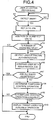
- Fig. 4 is a flowchart illustrating display operations of the MFP 10.
- the authentication section 17 continues a detection processing of a user.
- Fig. 5 is a diagram planarly illustrating a visual field range of the camera 22.
- the reference numerals described above represent same components as those shown in Fig. 1 ⁇ Fig. 4 .
- a visual field range F of the camera 22 is a stereo range.
- a user positioned in the vicinity of the MFP 10 is contained in the range.
- the camera 22 outputs a planar image area from the stereo visual field range F.
- the image area is a still image or a moving image.
- the image extraction section 214 detects an area of a moving target in the image area.
- the image extraction section 214 extracts the head of a person according to the size of a target in a changed area.
- the authentication section 17 repeats the processing in ACT A1 during a period of time a user isn't detected (NO in ACT A1).
- the authentication section 17 detects a user in ACT A1 (YES in ACT A1), the authentication section 17 and the job management section 16 refer to the job management table 25 in ACT A2.
- Fig. 6A is a diagram illustrating a first registration job of the job management section 16.
- the reference numerals described above represent same components as those shown in Fig. 1 ⁇ Fig. 5 .
- the job management section 16 detects a print job of the user A (registrant identification information and notation).
- the user B approaches the MFP 10 for a copy operation.
- the user C approaches the MFP 10 for a FAX transmission operation.
- the authentication section 17 adds the number of users in the vicinity of the MFP 10 and the number of the job registered users.
- the authentication section 17 determines whether or not the number of users is more than one according to the addition result.
- the authentication section 17 determines that the number of users is 2 or more than 2.
- the authentication section 17 terminates the processing.
- the MFP 10 is not occupied by a job of other people.
- the authentication section 17 If the authentication section 17 detects that the number of the users is 2 in ACT A4 (YES in ACT A4), the authentication section 17 identifies two users respectively through a face authentication in ACT A5.
- Fig. 7A is a diagram illustrating a correspondence relation of the database 215. User IDs and user identification information are represented.
- Fig. 7B is a diagram illustrating an example of storage content of face images in Fig. 7A .
- the reference numerals described above represent same components as those shown in Fig. 1 ⁇ Fig. 6 .
- Fig. 7B is an example of images stored in the address (address pointer) of the database 215.
- the "*000A" and the like indicates an address pointer.
- the image extraction section 214 extracts, for example, a contour line, and elements such as eyes, mouth, nose, ears, hairstyle, ornaments, color and the like within the contour line, and converts the feature points of the elements into numerical values.
- the authentication section 17 detects the user B and the user C. It is detected that the user B and the user C are positioned in the vicinity of the MFP 10.
- ACT A5 the main controller 21 or the OS calls the determination section 18 through an interruption to the bus 218 from the authentication section 17.
- the determination section 18 determines whether or not the user B and the user C are respectively a registrant of which the job has been registered in ACT A6.
- the determination section 18 compares a registrant of a registration job such as a print job with the identified users B and C.
- the determination section 18 determines whether or not both the user B and the user C are registrant of jobs.
- the determination section 18 refers to the job management table 25. Alternatively, the determination section 18 enables the job management section 16 to determine whether or not the users B and C are registrants.
- the determination section 18 determines whether or not all the identified users are users waiting for print output.
- the determination section 18 determines that neither of the users B and C is a registrant of job in ACT A7 (NO in ACT A7), the determination section 18 proceeds to the processing in ACT A8.
- the determination section 18 determines whether or not there is a compound control operation that can be processed in parallel to a print operation.
- the determination section 18 determines that there is a compound control operation in which a scan, a FAX transmission/reception and a mail transmission/reception of the scanner 11 can be carried out simultaneously in parallel to the print operation.
- the determination section 18 confirms that the obtained operation category is available in ACT A9.
- the main controller 21 displays a target user name and an operation name that can be used by the users B and C on the display section 19 in ACT A10.
- Fig. 8 is a diagram illustrating an example of display of the display section 19 in a case in which the number of waiting users is more than one.
- the reference numerals described above represent same components as shown in Fig. 1 ⁇ Fig. 7 .
- the determination section 18 may replace the orders according to the result in which orders are ranked before and after the identification time between the users B and C.
- the main controller 21 may output the target user name and the operation name from the speaker 26 through a sound.
- the user B sends a FAX when the user A is printing.
- the user C checks a mail reception after the user B.
- the MFP 10 can inform the user of other operations that are available.
- the authentication section 17 is not limited to detect a plurality of users simultaneously. A processing in a case in which the users B and C approach the MFP 10 with a time difference is described.
- the user C After the user B for a copy operation is detected by the authentication section 17 during the execution of the print job of the user A, the user C approaches the MFP 10 for a FAX transmission operation.
- the authentication section 17 starts the processing in ACT A1 through a detection of the user B.
- the authentication section 17 executes processing from ACT A2 to ACT A10.
- Fig. 9 is a diagram illustrating an example of display of the display section 19 in a case in which the number of waiting users is 1.
- the reference numerals described above represent same components as shown in Fig. 1 ⁇ Fig. 8 .
- the display section 19 displays the user B and an available operation name.
- the authentication section 17 authenticates the user C after the user B.
- the authentication section 17 starts the processing in ACT A1 through a detection of the user C.
- the authentication section 17 and the determination section 18 execute processing from ACT A2 to ACT A9 without carrying out branching processing in each processing.
- the display section 19 updates display content ( Fig. 8 ).
- the user B sends a FAX when the User A is carrying out the print operation.
- the user C sends a FAX after the user B.
- the user A generates a print job.
- the user B approaches the MFP 10 for a copy operation.
- the user C generates a print job.
- the job management section 16 registers print jobs of the users A and C before the processing in Fig. 4 is started.
- the authentication section 17 detects the user B through a detection processing, the authentication section 17 refers to the job management table 25 (ACT A2).
- the authentication section 17 adds the detected number of users and the number of job registered users (ACT A3).
- the authentication section 17 determines that the number of all the users is 3 (YES in ACT A4).
- the authentication section 17 identifies the user B through the face authentication (ACT A5).
- the determination section 18 determines whether or not the user B is a registrant (ACT A6 and ACT A7).
- the determination section 18 determines whether or not there is other operation with respect to the print operation according to the negative result in ACT A7 (ACT A8).
- the determination section 18 determines a scan, a FAX transmission/reception and a mail transmission/reception (YES in ACT A9).
- the display section 19 displays the user B and an available operation name as shown in Fig. 9 (ACT A10).
- the authentication section 17 carries out processing from ACT A1 to ACT A6 for the user C.
- ACT A7 the authentication section 17 determines the user C not to be an authentication target. Then, the authentication section 17 terminates the processing.
- the user B sends a FAX when the user A is carrying out a print job.
- the user B doesn't carry out a print job. A display is guided for the user B.
- the user C carries out a print job. No display is guided for the user C.
- the MFP 10 can control the display according to whether or not there is a user who carries out a print job.
- the user A generates a print job.
- the user B approaches the MFP 10 for a copy job.
- the job management section 16 registers a print job of the user A before the processing in Fig. 4 is started.
- the authentication section 17 detects the user B, the authentication section 17 refers to a registration of job (ACT A2).
- the authentication section 17 calculates the addition of the number of users (ACT A3), and determines that the number of users is 3 (ACT A4).
- the authentication section 17 determines whether or not the user B is registered through the face authentication (ACT A5, ACT A6 and ACT A7).
- the determination section 18 determines whether or not there is other operation different from the print operation (ACT A8).
- the determination section 18 determines a scan, a FAX transmission/reception and a mail transmission/reception (YES in ACT A9).
- the display section 19 displays the user B and an available operation name (ACT A10, Fig. 9 ).
- the user C approaches the MFP 10 for a scan mail.
- the authentication section 17 starts the processing in ACT A1 for the user C through a detection of the user C.
- the authentication section 17 executes processing from ACT A2 to ACT A9 without carrying out branching processing in each processing.
- the display section 19 updates display content as shown in Fig. 8 (ACT A10).
- the user B sends a FAX when the User A is carrying out the print operation.
- the user C sends a FAX after the user B.
- the ADF 33 conveys the document one by one.
- the ADF 33 stops a document at a given position temporarily.
- the scanner 11 images the reflected light on the CCD sensor 201.
- the CCD sensor 201 accumulates charge for each color.
- the scanner 11 generates a color signal for each pixel.
- the page memory 205 stores an image. An image scanned through an operation on the control panel 20 is mailed to an address.
- Fig. 10 is a diagram illustrating other registration job of the job management section 16.
- the reference numerals described above represent same components as shown in Fig. 1 ⁇ Fig. 9 .
- the job management section 16 registers three print jobs in the OS through the reception of a print request.
- the MFP 10 doesn't start the user detection processing in Fig. 4 .
- the print section 13 forms electrostatic latent images of four colors respectively on the corresponding drum 132.
- the print section 13 develops the electrostatic latent images of four colors respectively with corresponding toner.
- Each of the image forming sections 131C, 131M, 131Y and 131K transfers a corresponding toner image to the belt 30.
- the print section 13 forms monochrome toner images on the belt 130 sequentially from the upstream side to the downstream side in the anticlockwise direction V of the belt 130.
- the secondary transfer device 137 transfers a four-color toner image to the sheet P.
- the fixing device 138 fixes the four-color toner image on the sheet P.
- the MFP 10 prints and outputs a sheet for each user.
- the user A approaches the MFP 10 for a fax transmission job.
- the user B approaches the MFP 10 for a fax transmission job.
- the user C approaches the MFP 10 for a mail check.
- the authentication section 17 detects the user A (ACT A1), the authentication section 17 refers to a registration of job (ACT A2).
- Fig. 6B is a diagram illustrating a second registration job of the job management section of the image forming apparatus according to the embodiment.
- the reference numerals described above represent same components as those shown in Fig. 1 ⁇ Fig. 5 .
- the job management section 16 doesn't register any one print job.
- the authentication section 17 determines that the number of the users is 3.
- the authentication section 17 displays a guide of print, scan, FAX and mail as well as the user name A.
- the user A operates a FAX transmission button. After completion, the user B operates the FAX transmission button.
- the user C checks a mail reception.
- the MFP 10 promotes the users waiting for operations to access a FAX, a mail and a file inside the MFP 10 and the like, and in this way, the waiting user and a user who carries out a print job or a scan job can carry out operations simultaneously.
- the user can use a scan, FAX, and mail job during a print job without waiting for orders.
- the user doesn't wait operations until the print job that is being executed is ended.
- the MFP 10 may control a tilt and a pan of the camera 22 to rotate.
- the camera 22 may be arranged separately from the MFP 10.
- the MFP 10 may obtain users who approach the vicinity of the MFP 10 through a reception of an image from the separated camera 22.
- the MFP 10 may execute the personal authentication through an RFID (radio frequency identification) or a wireless medium such as a wireless tag.
- RFID radio frequency identification
- a wireless medium such as a wireless tag.
- the display section 19 and the speaker 26 may be arranged independently from the control panel 20.
- a piece of communication software in accordance with a communication protocol on the network 23 may be installed in the storage 14.
- a mailer for transmitting and receiving mails may be installed in the storage 14.
- An SSD solid state drive
- An SSD solid state drive
- the storage 14 may includes a memory interface 224.
- a piece of browser software on the window 140 of the control panel 20 may be installed in the storage 14.
- the job management section 16 may register and manage a browsing job.
- the MFP 10 may connect a USB (Universal Serial Bus) memory with the memory interface 224.
- USB Universal Serial Bus
- the job management section 16 may manage a job printing a file from the memory interface 224.
- the job management section 16 may store scanned data file in the USB memory.
- the MFP 10 may be provided with a finisher and may be connected with the finisher.
- the MFP 10 may contain and display a finisher processing in a candidate of a job category.
- the priorities of the image forming apparatus, the image forming method and the recording medium according to the embodiment are not damaged for the implementations which are only performed with these changes.
Landscapes
- Engineering & Computer Science (AREA)
- Theoretical Computer Science (AREA)
- Human Computer Interaction (AREA)
- Physics & Mathematics (AREA)
- General Engineering & Computer Science (AREA)
- General Physics & Mathematics (AREA)
- Multimedia (AREA)
- Signal Processing (AREA)
- Computer Security & Cryptography (AREA)
- Facsimiles In General (AREA)
- Accessory Devices And Overall Control Thereof (AREA)
Abstract
Description
- Embodiments described herein relate generally to an image forming apparatus or system, and a display method of the image forming apparatus.
- Conventionally, an MFP (multi-functional peripheral) incorporates a plurality of devices that can carry out compound control operations.
- The MFP cannot process a "print" job and a "copy" job through a network at the same time.
- On the other hand, the MFP is possible to process a "scan" job and a "print" job at the same time. The MFP can enable the user to use a "FAX transmission" operation as well as the "print" operation. Further, the MFP can enable the user to use a "mail transmission" operation as well as the "copy" operation.
- However, the MFP doesn't inform that the user can use other operations different from the "print" operation during the "print" operation.
- The user waits for print output after activating print jobs respectively.
- Other users come to the MFP for operations such as "scan", "FAX" and the like different from the "print" operation.
- During the execution of print operation, it is possible for the MFP to execute the "scan" operation and the "FAX" operation as well as the "print" operation.
- However, the user needs to wait for his/her turn. The user waits for an operation chance until the print operation that is being executed is ended.
- The MFP cannot run the plurality of devices efficiently, which hinders the improvement of operation efficiency of devices.
- To solve such problems, there is provided an image forming apparatus, comprising:
- a plurality of devices configured to carry out compound control operations;
- a job management section configured to store identification information of a job registered user using more than one of the plurality of devices in association with a job category;
- an authentication section configured to identify a user in the vicinity of the apparatus through a personal authentication separately from the job management section;
- a determination section configured to determine user identification information different from the identification information of the registrant among the user identification information of a plurality of users identified by the authentication section and other job category that can be used in the execution of the job; and
- a display section configured to display the user identification information and the other job category.
- Preferably, the image forming apparatus comprises:
- a control panel, wherein the display section is arranged on the control panel.
- Preferably still, the image forming apparatus further comprises:
- a speaker configured to output the user identification information and the other job category through sound.
- Preferably yet, the image forming apparatus further comprises:
- a camera, wherein the authentication section comprises a database in which a face image and the user identification information are associated; and
- an authentication control section configured to output the user identification information through an image captured by the camera and a face authentication of the face image.
- Suitably, the determination section ranks orders for the user identification information of a plurality of users obtained from the determination result.
- Suitably also, the determination section selects a job category that can be processed in parallel to the job category that has been registered in the job management section as the other job category.
- The invention also relates to a display method of the image forming apparatus, including:
- registering a job using more than one of a plurality of devices carrying out compound control operations in a job management section in which identification information of a registered user and a job category is associated;
- executing a personal authentication for a user in the vicinity of the apparatus;
- determining whether or not the user identified through the personal authentication has been registered in the job management section; and
- displaying the user identification information and a other job category that can be used in the execution of the job for a user who has not been registered in the job management section yet.
- Preferably, in the execution of the personal authentication, the user is photographed;
a face image is obtained from the photographed image and a database is retrieved; and
the user identification information of the plurality of users are listed through a face authentication of the face image. - Suitably, in the determination on whether or not the user has been registered, in a case in which user identification information of a plurality of users are obtained as the determination result, the user identification information of the plurality of users are ranked with orders.
- Suitably also, in the determination on whether or not the user has been registered, a job category that is processed in parallel to the job category from the job management section is assigned to the user identification information as the other job category.
- The invention further relates to an image forming system, comprising:
- a plurality of means configured to carry out compound control operations;
- a job management means configured to store identification information of a job registered user using more than one of the plurality of means in association with a job category;
- an authentication means configured to identify a user in the vicinity of the system through a personal authentication separately from the job management means;
- a determination means configured to determine user identification information different from the identification information of the registrant among the user identification information of a plurality of users identified by the authentication means and other job category that can be used in the execution of the job; and
- a display means configured to display the user identification information and the other job category.
- The above and other objects, features and advantages of the present invention will be made apparent from the following description of the preferred embodiments, given as non-limiting examples, with reference to the accompanying drawings, in which:
-
Fig. 1 is a diagram illustrating the constitution of an image forming apparatus according to an embodiment; -
Fig. 2 is a functional block diagram of the image forming apparatus according to the embodiment; -
Fig. 3 is a diagram illustrating a memory table of a job management section of the image forming apparatus according to the embodiment; -
Fig. 4 is a flowchart illustrating display operations of the image forming apparatus according to the embodiment; -
Fig. 5 is a diagram planarly illustrating a visual field range of a camera used in the image forming apparatus according to the embodiment; -
Fig. 6A is a diagram illustrating a first registration job of a job management section of the image forming apparatus according to the embodiment; -
Fig. 6B is a diagram illustrating a second registration job of a job management section of the image forming apparatus according to the embodiment; -
Fig. 7A is a diagram illustrating a correspondence relation of a database of the image forming apparatus according to the embodiment; -
Fig. 7B is a diagram illustrating an example of storage content of face images inFig. 7A ; -
Fig. 8 is a diagram illustrating a first display example of a display section of the image forming apparatus according to the embodiment; -
Fig. 9 is a diagram illustrating a second display example of the display section of the image forming apparatus according to the embodiment; and -
Fig. 10 is a diagram illustrating a third registration job of the job management section of the image forming apparatus according to the embodiment. - Certain embodiments provide an image forming apparatus, comprising: a plurality of devices configured to carry out compound control action; a job management section configured to store identification information of a job registered user using more than one of the plurality of devices in association with a job category; an authentication section configured to identify a user in the vicinity of the apparatus through a personal authentication separately from the job management section; a determination section configured to determine user identification information different from the identification information of the registrant among the user identification information of a plurality of users identified by the authentication section and other job categories that can be used in the execution of the job; and a display section configured to display the user identification information and the other job categories.
- Hereinafter, an image forming apparatus and a display method of the image forming apparatus according to the embodiment are described in detail with reference to the accompanying drawings. Further, same components in each figure are applied with the same reference numerals, and therefore the description thereof is not provided.
-
Fig. 1 is a diagram illustrating the constitution of an image forming apparatus according to the embodiment. - An
MFP 10 comprises a plurality of devices including ascanner 11, anetwork interface 12, aprint section 13, astorage 14, aFAX device 15 and the like. - The
scanner 11, thenetwork interface 12, theprint section 13, thestorage 14, and theFAX device 15 are devices. - For example, the
scanner 11 and theprint section 13 are capable of carrying out compound control operations. - The "capable of carrying out compound control operations" refers to capable of executing jobs such as the print job, the copy job and the like simultaneously.
- The
MFP 10 comprises ajob management section 16, anauthentication section 17, adetermination section 18, adisplay section 19, acontrol panel 20, amain controller 21 and acamera 22. - The
job management section 16 stores identification information of a job registered user using more than one of the devices such as thescanner 11, theprint section 13 and the like in association with a job category. - The
MFP 10 may use, for example, a staff ID (identification) as the identification information. - The
authentication section 17 identifies a user in the vicinity of theMFP 10 through a face authentication separately from thejob management section 16. Theauthentication section 17 authenticates an individual through the face authentication with thecamera 22. - The "in the vicinity of the
MFP 10" refers to a space in a range in which an authentication success rate of theauthentication section 17 higher than a desired threshold value can be obtained among all the spaces around theMFP 10. - The
determination section 18 determines user identification information different from the identification information of the job registrant among the plurality of user identification information identified by theauthentication section 17 and other job category that can be used during the execution of job. - The other job category is, for example, a FAX transmission job of a user B during a period of time a user A is carrying out a print job of a large number of pages.
- The
display section 19 displays the user identification information and the other job category. - The
scanner 11 scans documents from an ADF (Automatic Document Feeder) 33. TheADF 33 presses a document against aglass plate 32. - The
scanner 11 reflects light from alight source 27 on theglass plate 32. The reflected light is received by a CCD (charge coupled device)sensor 201 throughmirrors lens 31. - The
network interface 12 receives print request from a PC (personal computer) 24 through anetwork 23. Thenetwork interface 12 is an LAN (local area network) card. - The
print section 13 is a print engine which prints and outputs an image with four print colors (C, M, Y and K). - The
print section 13 comprises fourexposure devices 129,image forming sections belt 130. - The
exposure device 129 modulates a laser light of a semiconductor laser of each color through an image signal. Thebelt 130 travels endlessly in an anticlockwise direction V. - The
image forming section 131Y for forming a yellow image is provided with adrum 132, acharger 133, a developingdevice 134 and atransfer device 135. - The
drum 132 is a photoconductor drum which rotates in a clockwise direction T. - The
charger 133 charges the surface of thedrum 132. - The developing
device 134 develops an electrostatic latent image on thedrum 132 with toner. - The
transfer device 135 primarily transfers a toner image on thedrum 132 to thebelt 130. - Each of the constitutions of the
image forming section 131M for forming a magenta image, theimage forming section 131C for forming a cyan image and theimage forming section 131K for forming a black image are substantially identical to the constitution of theimage forming section 131Y. - Further, the
print section 13 is provided with asheet conveyer 136, asecondary transfer device 137, and afixing device 138. - The
sheet conveyer 136 guides a sheet P from atray 139 to theprint section 13. - The
secondary transfer device 137 transfers a four-color toner image formed by theimage forming sections - The fixing
device 138 fixes the toner image that has not been fixed yet on the sheet P. - The
FAX device 15 serving as a device sends an image through a FAX. TheFAX device 15 also receives an image through a FAX. -
Fig. 2 is a functional block diagram of an image forming apparatus according to the embodiment. The reference numerals described above represent same components as those shown inFig. 1 .Fig. 2 mainly illustrates acontrol system 50 of theMFP 10. - The
control system 50 includes an ROM (read only memory) 212, an RAM (random access memory) 213, and a CPU (central processing unit) 219 on abus 218 and abus 223. - The
buses - The ROM 212 stores programs.
- The
CPU 219 controls theRAM 213 according to the programs. TheCPU 219 outputs signals indicating setting and instruction to each device (theprint section 13 and the like) through thebuses - The
CPU 219 reads out a processing result of each device. TheCPU 219 executes the functions of themain controller 21. TheCPU 219 collectively controls thewhole control system 50 of theMFP 10. - The
RAM 213 provided a storage area for operation to theCPU 219. TheRAM 213 generates a memory table for managing jobs of the OS. - The
job management section 16 stores a list of processing operations such as the print job registered through thePC 24 via thenetwork 23. Thejob management section 16 manages the processing operations according to the job categories. - The
job management section 16 uses a job management table 25 of the OS. -
Fig. 3 is a diagram illustrating an example of the job management table of thejob management section 16. The reference numerals described above represent same components as those shown inFig. 1 andFig. 2 . - The job categories refers to a copy job, a print job, a scan job, an FAX transmission job, an FAX reception job, a mail transmission job and a mail reception job.
- The copy job is a job printing the data scanned through the
scanner 11 with theprint section 13. - The print job is a job printing a print spool data from the
PC 24 with theprint section 13. - The scan job is a job sending the scanned data to a remote server through the
network 23. - The scan job includes a job mailing the scanned data to an address. The scan job also includes a job storing the scanned data in the
storage 14. - The FAX transmission job is a job transmitting the scanned data through a FAX.
- The FAX reception job is a job printing the image data received by the
FAX device 15 with theprint section 13. - The mail transmission job is a job mailing the file stored in the
storage 14 to an address. The mail transmission job also includes a job mailing a scanned image to an address. - The mail reception job is a job receiving a mail.
- Further, in
Fig. 2 , a first HDD (hard disk drive) 216 and a second HDD (hard disk drive) 217 are used in thestorage 14. - The
HDD 216 stores various kinds of files generated when theMFP 10 carries out processing. For example, theHDD 216 stores a scanned file. - The
HDD 217 may store adatabase 215 for authentication. Thedatabase 215 stores a plurality of face images and corresponding user identification information in an associated manner. - The
database 215 stores the face image, the user identification information and user feature information in an associated manner. - Any of the
HDDs - The OS manages the generation of jobs through a plurality of devices (the
scanner 11 and the print section 13). - The
FAX device 15 may store the image data received through a FAX in thestorage 14. - The
authentication section 17 authenticates an individual through the face authentication with thecamera 22. - The
camera 22 acquires an image including a user in the vicinity of theMFP 10. Thecamera 22 has a wide field of view (angle of view). - For example, a CMOS (complementary MOS) image sensor is used in the
camera 22. - The
authentication section 17 comprises an image extraction section 214 and anauthentication control section 204. - The image extraction section 214 detects a person according to the image data from the
camera 22. The image extraction section 214 extracts feature information for indentifying a face from the image data. - The
authentication control section 204 may output an image capturing timing signal to thecamera 22. - The
authentication control section 204 outputs user identification information through the face authentication according to the captured image from thecamera 22 and the face image of thedatabase 215. - The
authentication control section 204 compares the feature information extracted by the image feature section 214 with feature information of the user registered in thesecond HDD 217 in advance. Theauthentication control section 204 identifies a user according to the comparison result to authenticate the user. - Further, the
determination section 18 determines identification information representing a non-registered user who has not been registered in thejob management section 16 yet among the plurality of users identified by theauthentication section 17 as the user identification information. - The
determination section 18 may rank orders for user identification information of a plurality of users obtained as the determination results. - The
determination section 18 selects other job category that can be used by the non-registered user when a job is being executed. - The
determination section 18 selects a job category that can be processed in parallel to a job category that has been registered in thejob management section 16 as the other job category. - The
determination section 18 may be arranged in a compound controlsection determination section 222. - The functions required to determine compound control operations other than the functions of the
determination section 18 are executed by the compound controlsection determination section 222. - The compound control
section determination section 222 is executed through cooperation of theCPU 219, the ROM 212 and theRAM 213. - The
MFP 10 includes thedisplay section 19 on thecontrol panel 20. Thedisplay section 19 displays, for example, a user name and information such as "scan is available". - The
MFP 10 may include aspeaker 26 in thecontrol panel 20. Thespeaker 26 outputs the user identification information and the job category through sound with an amplifier. - The
control panel 20 includes aninput section 210. Theinput section 210 includes buttons and numeric keys for receiving operations of users. - The
control system 50 is provided with a controlpanel control section 209. - The control
panel control section 209 controls theinput section 210 and a display section 211. The controlpanel control section 209 controls a display of screen, a switch of screen on thecontrol panel 20 and an input of operations of the user. - The
control system 50 includes anetwork control section 220 for controlling a network communication. - The
control system 50 includes a printerimage processing section 207. - The printer
image processing section 207 executes a filtering processing and a gradation processing on the image data to be sent to theprint section 13. - The
printer control section 208 controls a printing operation of theprint section 13. - The
control system 50 includes aCCD sensor 201, aCCD pre-processing section 202, a scannerimage processing section 203, apage memory 205, and a pagememory control section 206. - The
CCD sensor 201 is a four-line CCD in thescanner 11. TheCCD sensor 201 reads a document in the horizontal scanning direction through CCD elements. TheCCD sensor 201 converts the read document into image data through a scanning in the vertical scanning direction. - The
CCD pre-processing section 202 converts an analog signal of four-color from theCCD sensor 201 into a digital signal. - The
CCD pre-processing section 202 generates a driving signal of the CCD elements. - The scanner
image processing section 203 corrects the bending of a curve representing characteristics of the CCD elements. The scannerimage processing section 203 carries out an image processing required in next stage processing. For example, the processing is a correction of thelens 31 and the like, a range correction, a filter processing and the like. - The
page memory 205 stores page data of one page or more than one page of the document. - The page
memory control section 206 controls read access and write access to thepage memory 205. - A part of components shown in
Fig. 2 is according to the control procedure of thebuses main controller 21 mediates data transmission between components. - Each component of the
control system 50 is realized through a semiconductor circuit such as an LSI (large scale integration) and the like. Thecontrol system 50 may be realized through software partially or wholly. - Further, a display method of the image forming apparatus according to the present embodiment is a method notifying a user from the
MFP 10. - The
main controller 21 enables thejob management section 16 to register a job using theprint section 13, thescanner 11 and the like. - The
main controller 21 enables theauthentication section 17 to execute a face authentication for a user in the vicinity of theMFP 10. - The
main controller 21 enables thedetermination section 18 to determine whether or not the user identified through the face authentication has been registered in thejob management section 16. - The
main controller 21 sends a control signal to thecontrol panel 20. - The
main controller 21 enables thedisplay section 19 to display user identification information and other job category that can be used in the execution of the job for a non-registered user who has not been registered in thejob management section 16 yet. - In the determination, in a case in which it is determined that user identification information of a plurality of users is obtained, the
determination section 18 may rank orders for the user identification information of the plurality of users. - In the determination, the
determination section 18 assigns a job category processed in parallel to the job category from thejob management section 16 to user identification information. - In the execution of the face authentication, the
authentication section 17 photographs the user through thecamera 22. - The
authentication section 17 obtains a face image from the photographed image and retrieves thedatabase 215. - The
authentication section 17 lists the user identification information of the plurality of users through a face authentication of the face image. - Next, the operation actions of the
MFP 10 with the constitution described above are described. -
Fig. 4 is a flowchart illustrating display operations of theMFP 10. Theauthentication section 17 continues a detection processing of a user. -
Fig. 5 is a diagram planarly illustrating a visual field range of thecamera 22. The reference numerals described above represent same components as those shown inFig. 1∼Fig. 4 . - A visual field range F of the
camera 22 is a stereo range. A user positioned in the vicinity of theMFP 10 is contained in the range. Thecamera 22 outputs a planar image area from the stereo visual field range F. The image area is a still image or a moving image. - The image extraction section 214 detects an area of a moving target in the image area. The image extraction section 214 extracts the head of a person according to the size of a target in a changed area.
- Further, in ACT A1 in
Fig. 4 , theauthentication section 17 repeats the processing in ACT A1 during a period of time a user isn't detected (NO in ACT A1). - If the
authentication section 17 detects a user in ACT A1 (YES in ACT A1), theauthentication section 17 and thejob management section 16 refer to the job management table 25 in ACT A2. - It is assumed that the
job management section 16 has registered the print jobs in the OS through the reception of a print request from thePC 24 of the user A in thenetwork interface 12 prior to ACT A1. -
Fig. 6A is a diagram illustrating a first registration job of thejob management section 16. The reference numerals described above represent same components as those shown inFig. 1∼Fig. 5 . - In ACT A2, the
job management section 16 detects a print job of the user A (registrant identification information and notation). - On the other hand, the user B approaches the
MFP 10 for a copy operation. - The user C approaches the
MFP 10 for a FAX transmission operation. - In ACT A3, the
authentication section 17 adds the number of users in the vicinity of theMFP 10 and the number of the job registered users. - In ACT A4, the
authentication section 17 determines whether or not the number of users is more than one according to the addition result. - In ACT A4, the
authentication section 17 determines that the number of users is 2 or more than 2. - Herein, if it is determined in ACT A4 that the number of users is 1 (NO in ACT A4), the
authentication section 17 terminates the processing. - If the number of the users is 1, the
MFP 10 is not occupied by a job of other people. - If the
authentication section 17 detects that the number of the users is 2 in ACT A4 (YES in ACT A4), theauthentication section 17 identifies two users respectively through a face authentication in ACT A5. -
Fig. 7A is a diagram illustrating a correspondence relation of thedatabase 215. User IDs and user identification information are represented. -
Fig. 7B is a diagram illustrating an example of storage content of face images inFig. 7A . The reference numerals described above represent same components as those shown inFig. 1∼Fig. 6 .Fig. 7B is an example of images stored in the address (address pointer) of thedatabase 215. The "*000A" and the like indicates an address pointer. - In ACT A5, the image extraction section 214 extracts, for example, a contour line, and elements such as eyes, mouth, nose, ears, hairstyle, ornaments, color and the like within the contour line, and converts the feature points of the elements into numerical values.
- In ACT A5, the
authentication section 17 detects the user B and the user C. It is detected that the user B and the user C are positioned in the vicinity of theMFP 10. - In ACT A5, the
main controller 21 or the OS calls thedetermination section 18 through an interruption to thebus 218 from theauthentication section 17. - Sequentially, the
determination section 18 determines whether or not the user B and the user C are respectively a registrant of which the job has been registered in ACT A6. - In ACT A6, the
determination section 18 compares a registrant of a registration job such as a print job with the identified users B and C. - In ACT A7, the
determination section 18 determines whether or not both the user B and the user C are registrant of jobs. - In ACT A7, the
determination section 18 refers to the job management table 25. Alternatively, thedetermination section 18 enables thejob management section 16 to determine whether or not the users B and C are registrants. - The
determination section 18 determines whether or not all the identified users are users waiting for print output. - If the
determination section 18 determines that neither of the users B and C is a registrant of job in ACT A7 (NO in ACT A7), thedetermination section 18 proceeds to the processing in ACT A8. - It is determined by the
determination section 18 that the users B and C are persons who approach theMFP 10 for some unknown purposes. - In ACT A8, the
determination section 18 determines whether or not there is a compound control operation that can be processed in parallel to a print operation. - In ACT A8, the
determination section 18 determines that there is a compound control operation in which a scan, a FAX transmission/reception and a mail transmission/reception of thescanner 11 can be carried out simultaneously in parallel to the print operation. - Next, the
determination section 18 confirms that the obtained operation category is available in ACT A9. - If the confirmation result is yes (YES in ACT A9), the
main controller 21 displays a target user name and an operation name that can be used by the users B and C on thedisplay section 19 in ACT A10. -
Fig. 8 is a diagram illustrating an example of display of thedisplay section 19 in a case in which the number of waiting users is more than one. The reference numerals described above represent same components as shown inFig. 1∼Fig. 7 . - The
determination section 18 may replace the orders according to the result in which orders are ranked before and after the identification time between the users B and C. - In ACT A10, the
main controller 21 may output the target user name and the operation name from thespeaker 26 through a sound. - The user B sends a FAX when the user A is printing.
- The user C checks a mail reception after the user B.
- In this way, in a case in which a user of which the job has not been registered in the
MFP 10 is positioned in the vicinity of theMFP 10, theMFP 10 can inform the user of other operations that are available. - It is always possible to promote a plurality of users to use available compound control operations.
- In ACT A3 described above, the
authentication section 17 is not limited to detect a plurality of users simultaneously. A processing in a case in which the users B and C approach theMFP 10 with a time difference is described. - After the user B for a copy operation is detected by the
authentication section 17 during the execution of the print job of the user A, the user C approaches theMFP 10 for a FAX transmission operation. - The
authentication section 17 starts the processing in ACT A1 through a detection of the user B. - The
authentication section 17 executes processing from ACT A2 to ACT A10. -
Fig. 9 is a diagram illustrating an example of display of thedisplay section 19 in a case in which the number of waiting users is 1. The reference numerals described above represent same components as shown inFig. 1∼Fig. 8 . - The
display section 19 displays the user B and an available operation name. - The
authentication section 17 authenticates the user C after the user B. - During the execution of the print job of the user A, and during the execution of the processing of the user B, the
authentication section 17 starts the processing in ACT A1 through a detection of the user C. - The
authentication section 17 and thedetermination section 18 execute processing from ACT A2 to ACT A9 without carrying out branching processing in each processing. - In ACT A10, the
display section 19 updates display content (Fig. 8 ). - For example, the user B sends a FAX when the User A is carrying out the print operation. The user C sends a FAX after the user B.
- The user A generates a print job.
- The user B approaches the
MFP 10 for a copy operation. - The user C generates a print job.
- The
job management section 16 registers print jobs of the users A and C before the processing inFig. 4 is started. - If the
authentication section 17 detects the user B through a detection processing, theauthentication section 17 refers to the job management table 25 (ACT A2). - The
authentication section 17 adds the detected number of users and the number of job registered users (ACT A3). - The
authentication section 17 determines that the number of all the users is 3 (YES in ACT A4). - The
authentication section 17 identifies the user B through the face authentication (ACT A5). - The
determination section 18 determines whether or not the user B is a registrant (ACT A6 and ACT A7). - The
determination section 18 determines whether or not there is other operation with respect to the print operation according to the negative result in ACT A7 (ACT A8). - The
determination section 18 determines a scan, a FAX transmission/reception and a mail transmission/reception (YES in ACT A9). - The
display section 19 displays the user B and an available operation name as shown inFig. 9 (ACT A10). - The
authentication section 17 carries out processing from ACT A1 to ACT A6 for the user C. In ACT A7, theauthentication section 17 determines the user C not to be an authentication target. Then, theauthentication section 17 terminates the processing. - The user B sends a FAX when the user A is carrying out a print job.
- The user B doesn't carry out a print job. A display is guided for the user B.
- The user C carries out a print job. No display is guided for the user C.
- The
MFP 10 can control the display according to whether or not there is a user who carries out a print job. - Instead of the print job of the user C in the case (C), there is also a case in which the user C approaches the
MFP 10 for a scan mail (mail transmission of a scan image). - The user A generates a print job.
- The user B approaches the
MFP 10 for a copy job. - The
job management section 16 registers a print job of the user A before the processing inFig. 4 is started. - If the
authentication section 17 detects the user B, theauthentication section 17 refers to a registration of job (ACT A2). Theauthentication section 17 calculates the addition of the number of users (ACT A3), and determines that the number of users is 3 (ACT A4). - The
authentication section 17 determines whether or not the user B is registered through the face authentication (ACT A5, ACT A6 and ACT A7). - The
determination section 18 determines whether or not there is other operation different from the print operation (ACT A8). - The
determination section 18 determines a scan, a FAX transmission/reception and a mail transmission/reception (YES in ACT A9). - The
display section 19 displays the user B and an available operation name (ACT A10,Fig. 9 ). - The user C approaches the
MFP 10 for a scan mail. - During the execution of the print job of the user A, and during the execution of the processing of the user B, the
authentication section 17 starts the processing in ACT A1 for the user C through a detection of the user C. - The
authentication section 17 executes processing from ACT A2 to ACT A9 without carrying out branching processing in each processing. Thedisplay section 19 updates display content as shown inFig. 8 (ACT A10). - For example, the user B sends a FAX when the User A is carrying out the print operation. The user C sends a FAX after the user B.
- For example, 1000 pieces of documents are set in the
ADF 33. TheADF 33 conveys the document one by one. TheADF 33 stops a document at a given position temporarily. - The
scanner 11 images the reflected light on theCCD sensor 201. TheCCD sensor 201 accumulates charge for each color. Thescanner 11 generates a color signal for each pixel. - The
page memory 205 stores an image. An image scanned through an operation on thecontrol panel 20 is mailed to an address. -
Fig. 10 is a diagram illustrating other registration job of thejob management section 16. The reference numerals described above represent same components as shown inFig. 1∼Fig. 9 . - The
job management section 16 registers three print jobs in the OS through the reception of a print request. - The
MFP 10 doesn't start the user detection processing inFig. 4 . - The
print section 13 forms electrostatic latent images of four colors respectively on thecorresponding drum 132. Theprint section 13 develops the electrostatic latent images of four colors respectively with corresponding toner. - Each of the
image forming sections belt 30. - The
print section 13 forms monochrome toner images on thebelt 130 sequentially from the upstream side to the downstream side in the anticlockwise direction V of thebelt 130. - The
secondary transfer device 137 transfers a four-color toner image to the sheet P. The fixingdevice 138 fixes the four-color toner image on the sheet P. - The
MFP 10 prints and outputs a sheet for each user. - The user A approaches the
MFP 10 for a fax transmission job. - The user B approaches the
MFP 10 for a fax transmission job. - The user C approaches the
MFP 10 for a mail check. - If the
authentication section 17 detects the user A (ACT A1), theauthentication section 17 refers to a registration of job (ACT A2). -
Fig. 6B is a diagram illustrating a second registration job of the job management section of the image forming apparatus according to the embodiment. The reference numerals described above represent same components as those shown inFig. 1∼Fig. 5 . - The
job management section 16 doesn't register any one print job. - In a case in which the
authentication section 17 detects that 3 persons are in the visual field range F simultaneously, theauthentication section 17 determines that the number of the users is 3. - According to a determination on whether or not the user A is registered through the face authentication, the
authentication section 17 displays a guide of print, scan, FAX and mail as well as the user name A. - The user A operates a FAX transmission button. After completion, the user B operates the FAX transmission button.
- Both the FAX transmission of the user A and the FAX transmission of the user B are buffered.
- During a period of time the users A and B are waiting for the transmission, the user C checks a mail reception.
- As stated above in detail, the
MFP 10 promotes the users waiting for operations to access a FAX, a mail and a file inside theMFP 10 and the like, and in this way, the waiting user and a user who carries out a print job or a scan job can carry out operations simultaneously. - In this way, it is possible to run the plurality of devices that can carry out compound control operations efficiently.
- The user can use a scan, FAX, and mail job during a print job without waiting for orders. The user doesn't wait operations until the print job that is being executed is ended.
- The operation efficiency of devices is improved.
- The processing as shown in
Figs 1∼10 is exemplified. The image forming apparatus according to the present embodiment is not limited to the processing disclosed in the accompanying drawings. - In the embodiment described above, the
MFP 10 may control a tilt and a pan of thecamera 22 to rotate. - The
camera 22 may be arranged separately from theMFP 10. TheMFP 10 may obtain users who approach the vicinity of theMFP 10 through a reception of an image from the separatedcamera 22. - The
MFP 10 may execute the personal authentication through an RFID (radio frequency identification) or a wireless medium such as a wireless tag. - The
display section 19 and thespeaker 26 may be arranged independently from thecontrol panel 20. - A piece of communication software in accordance with a communication protocol on the
network 23 may be installed in thestorage 14. A mailer for transmitting and receiving mails may be installed in thestorage 14. - An SSD (solid state drive) may be used in the
storage 14. - The
storage 14 may includes amemory interface 224. - A piece of browser software on the
window 140 of thecontrol panel 20 may be installed in thestorage 14. Thejob management section 16 may register and manage a browsing job. - The
MFP 10 may connect a USB (Universal Serial Bus) memory with thememory interface 224. - The
job management section 16 may manage a job printing a file from thememory interface 224. Thejob management section 16 may store scanned data file in the USB memory. - In the embodiment described above, the
MFP 10 may be provided with a finisher and may be connected with the finisher. TheMFP 10 may contain and display a finisher processing in a candidate of a job category. - The priorities of the image forming apparatus, the image forming method and the recording medium according to the embodiment are not damaged for the implementations which are only performed with these changes.
- While certain embodiments have been described, these embodiments have been presented by way of example only, and are not intended to limit the scope of the invention. Indeed, the novel embodiments described herein may be embodied in a variety of other forms; furthermore, various omissions, substitutions and changes in the form of the embodiments described herein may be made without departing from the framework of the invention. The accompanying claims and their equivalents are intended to cover such forms or modifications as would fall within the scope and spirit of the invention.
Claims (11)
- An image forming apparatus, comprising:a plurality of devices configured to carry out compound control operations;a job management section configured to store identification information of a job registered user using more than one of the plurality of devices in association with a job category;an authentication section configured to identify a user in the vicinity of the apparatus through a personal authentication separately from the job management section;a determination section configured to determine user identification information different from the identification information of the registrant among the user identification information of a plurality of users identified by the authentication section and other job category that can be used in the execution of the job; anda display section configured to display the user identification information and the other job category.
- The image forming apparatus according to claim 1, further comprising:a control panel, whereinthe display section is arranged on the control panel.
- The image forming apparatus according to claim 1 or 2, further comprising:a speaker configured to output the user identification information and the other job category through sound.
- The image forming apparatus according to any one of claims 1 to 3, further comprising:a camera, whereinthe authentication section comprises a database in which a face image and the user identification information are associated; andan authentication control section configured to output the user identification information through an image captured by the camera and a face authentication of the face image.
- The image forming apparatus according to any one of claims 1 to 4, wherein the determination section ranks orders for the user identification information of a plurality of users obtained from the determination result.
- The image forming apparatus according to any one of claims 1 to 4, wherein the determination section selects a job category that can be processed in parallel to the job category that has been registered in the job management section as the other job category.
- A display method of the image forming apparatus, including:registering a job using more than one of a plurality of devices carrying out compound control operations in a job management section in which identification information of a registered user and a job category is associated;executing a personal authentication for a user in the vicinity of the apparatus;determining whether or not the user identified through the personal authentication has been registered in the job management section; anddisplaying the user identification information and a other job category that can be used in the execution of the job for a user who has not been registered in the job management section yet.
- The method according to claim 7, wherein
in the execution of the personal authentication, the user is photographed;
a face image is obtained from the photographed image and a database is retrieved; and
the user identification information of the plurality of users are listed through a face authentication of the face image. - The method according to claim 7 or 8, wherein
in the determination on whether or not the user has been registered, in a case in which user identification information of a plurality of users are obtained as the determination result, the user identification information of the plurality of users are ranked with orders. - The method according to claim 7 or 8, wherein
in the determination on whether or not the user has been registered, a job category that is processed in parallel to the job category from the job management section is assigned to the user identification information as the other job category. - An image forming system, comprising:a plurality of means configured to carry out compound control operations;a job management means configured to store identification information of a job registered user using more than one of the plurality of means in association with a job category;an authentication means configured to identify a user in the vicinity of the system through a personal authentication separately from the job management means;a determination means configured to determine user identification information different from the identification information of the registrant among the user identification information of a plurality of users identified by the authentication means and other job category that can be used in the execution of the job; anda display means configured to display the user identification information and the other job category.
Applications Claiming Priority (1)
| Application Number | Priority Date | Filing Date | Title |
|---|---|---|---|
| US14/813,401 US20170034383A1 (en) | 2015-07-30 | 2015-07-30 | Information display apparatus and information displaying method of information display apparatus |
Publications (2)
| Publication Number | Publication Date |
|---|---|
| EP3125105A1 true EP3125105A1 (en) | 2017-02-01 |
| EP3125105B1 EP3125105B1 (en) | 2021-09-08 |
Family
ID=56092767
Family Applications (1)
| Application Number | Title | Priority Date | Filing Date |
|---|---|---|---|
| EP16171454.8A Not-in-force EP3125105B1 (en) | 2015-07-30 | 2016-05-26 | Image forming apparatus and display method of the image forming apparatus |
Country Status (3)
| Country | Link |
|---|---|
| US (1) | US20170034383A1 (en) |
| EP (1) | EP3125105B1 (en) |
| CN (1) | CN106412358A (en) |
Cited By (1)
| Publication number | Priority date | Publication date | Assignee | Title |
|---|---|---|---|---|
| JP2019010794A (en) * | 2017-06-30 | 2019-01-24 | 京セラドキュメントソリューションズ株式会社 | Image forming apparatus |
Families Citing this family (6)
| Publication number | Priority date | Publication date | Assignee | Title |
|---|---|---|---|---|
| US10831880B2 (en) * | 2016-09-07 | 2020-11-10 | Ricoh Company, Ltd. | Information processing apparatus, information processing system, information processing method, and computer-readable recording medium for facial recognition registration and verification |
| JP7017034B2 (en) * | 2017-07-21 | 2022-02-08 | 富士フイルムビジネスイノベーション株式会社 | Image processing device and image processing program |
| CN107369354B (en) * | 2017-08-16 | 2019-12-24 | 南昌市龙诚电器设备有限公司 | Automobile driving simulation device based on virtual reality technology |
| JP2019062455A (en) * | 2017-09-27 | 2019-04-18 | キヤノン株式会社 | IMAGE FORMING APPARATUS, CONTROL METHOD THEREOF, AND PROGRAM |
| CN109960906A (en) * | 2017-12-25 | 2019-07-02 | 柯尼卡美能达办公系统研发(无锡)有限公司 | Authentication device, image forming apparatus and authentication method |
| JP2021024093A (en) * | 2019-07-31 | 2021-02-22 | キヤノン株式会社 | Image formation apparatus, control method of image formation apparatus and computer program |
Citations (2)
| Publication number | Priority date | Publication date | Assignee | Title |
|---|---|---|---|---|
| US20140123023A1 (en) * | 2012-10-30 | 2014-05-01 | Canon Kabushiki Kaisha | Information processing apparatus, information processing method, and computer-readable storage medium |
| US20150055168A1 (en) * | 2013-08-20 | 2015-02-26 | Toshiba Tec Kabushiki Kaisha | System to manage operation of devices |
Family Cites Families (12)
| Publication number | Priority date | Publication date | Assignee | Title |
|---|---|---|---|---|
| JP4621103B2 (en) * | 2005-10-12 | 2011-01-26 | キヤノン株式会社 | Image forming apparatus and method of controlling image forming apparatus |
| JP5002277B2 (en) * | 2007-02-06 | 2012-08-15 | キヤノン株式会社 | Job processing apparatus, method for controlling job processing apparatus, storage medium, and program |
| US8593672B2 (en) * | 2009-05-01 | 2013-11-26 | Konica Minolta Business Technologies, Inc. | Information equipment apparatus |
| JP5488224B2 (en) * | 2010-06-09 | 2014-05-14 | 株式会社リコー | Image processing apparatus, distributed printing system, distributed printing method, and program |
| JP5271328B2 (en) * | 2010-09-28 | 2013-08-21 | シャープ株式会社 | Operation device and image forming apparatus |
| US8261090B1 (en) * | 2011-09-28 | 2012-09-04 | Google Inc. | Login to a computing device based on facial recognition |
| JP5902922B2 (en) * | 2011-11-10 | 2016-04-13 | キヤノン株式会社 | Image forming apparatus, image forming apparatus control method, and program |
| JP6201515B2 (en) * | 2013-08-19 | 2017-09-27 | 株式会社リコー | Image forming apparatus, image forming method, and image forming program |
| JP6172570B2 (en) * | 2013-09-13 | 2017-08-02 | ブラザー工業株式会社 | Printing device |
| JP5914442B2 (en) * | 2013-09-30 | 2016-05-11 | 株式会社沖データ | Data processing apparatus and method, and image processing apparatus |
| JP5889855B2 (en) * | 2013-10-11 | 2016-03-22 | シャープ株式会社 | Image forming apparatus |
| JP2016066241A (en) * | 2014-09-25 | 2016-04-28 | キヤノン株式会社 | Information processing apparatus, control method thereof, and program |
-
2015
- 2015-07-30 US US14/813,401 patent/US20170034383A1/en not_active Abandoned
-
2016
- 2016-05-26 EP EP16171454.8A patent/EP3125105B1/en not_active Not-in-force
- 2016-06-23 CN CN201610466959.3A patent/CN106412358A/en active Pending
Patent Citations (2)
| Publication number | Priority date | Publication date | Assignee | Title |
|---|---|---|---|---|
| US20140123023A1 (en) * | 2012-10-30 | 2014-05-01 | Canon Kabushiki Kaisha | Information processing apparatus, information processing method, and computer-readable storage medium |
| US20150055168A1 (en) * | 2013-08-20 | 2015-02-26 | Toshiba Tec Kabushiki Kaisha | System to manage operation of devices |
Cited By (1)
| Publication number | Priority date | Publication date | Assignee | Title |
|---|---|---|---|---|
| JP2019010794A (en) * | 2017-06-30 | 2019-01-24 | 京セラドキュメントソリューションズ株式会社 | Image forming apparatus |
Also Published As
| Publication number | Publication date |
|---|---|
| EP3125105B1 (en) | 2021-09-08 |
| US20170034383A1 (en) | 2017-02-02 |
| CN106412358A (en) | 2017-02-15 |
Similar Documents
| Publication | Publication Date | Title |
|---|---|---|
| EP3125105B1 (en) | Image forming apparatus and display method of the image forming apparatus | |
| CN104079749B (en) | Image processing system and image forming method | |
| US20110107402A1 (en) | Client server system, client apparatus and server apparatus displaying contents of provided services | |
| US8508796B2 (en) | Image forming apparatus, method and program for selectively printing with transparent and non-transparent printing agents | |
| US10070001B2 (en) | Document reading apparatus, method for controlling document reading apparatus, and storage medium | |
| US8203724B2 (en) | Image forming apparatus and control method therefor, as well as program for implementing the control method | |
| US10313536B2 (en) | Information processing system, electronic apparatus, information processing apparatus, information processing method, electronic apparatus processing method and non-transitory computer readable medium to confirm difference in meeting contents using sound information | |
| JP6201515B2 (en) | Image forming apparatus, image forming method, and image forming program | |
| EP2645269A2 (en) | Digitizing apparatus | |
| US9819831B2 (en) | Image forming apparatus and notification method for image forming apparatus | |
| JP6991072B2 (en) | Image reader, image forming device and control method | |
| US11656824B2 (en) | Image forming system | |
| US7911628B2 (en) | Print system and control method therefor | |
| JP2021193780A (en) | Image reader, image reading method, and image reading program | |
| US10412259B2 (en) | Document reading apparatus and image forming apparatus | |
| US11194530B2 (en) | Image forming apparatus that displays status of job instructed by user | |
| JP6988679B2 (en) | Image formation system | |
| US10768875B2 (en) | Image forming system for executing confidential print job based on location of sender | |
| JP2012186716A (en) | File name creation device and file name creation program | |
| US20130182291A1 (en) | Information processing apparatus, image forming apparatus and system | |
| US20130182278A1 (en) | Image forming apparatus and job control method | |
| JP6500842B2 (en) | Printing system | |
| JP2015104863A (en) | Image forming apparatus and image forming method | |
| JP2021072503A (en) | Image forming apparatus | |
| JP2007317020A (en) | Data processing apparatus and license information management apparatus |
Legal Events
| Date | Code | Title | Description |
|---|---|---|---|
| PUAI | Public reference made under article 153(3) epc to a published international application that has entered the european phase |
Free format text: ORIGINAL CODE: 0009012 |
|
| STAA | Information on the status of an ep patent application or granted ep patent |
Free format text: STATUS: THE APPLICATION HAS BEEN PUBLISHED |
|
| AK | Designated contracting states |
Kind code of ref document: A1 Designated state(s): AL AT BE BG CH CY CZ DE DK EE ES FI FR GB GR HR HU IE IS IT LI LT LU LV MC MK MT NL NO PL PT RO RS SE SI SK SM TR |
|
| AX | Request for extension of the european patent |
Extension state: BA ME |
|
| STAA | Information on the status of an ep patent application or granted ep patent |
Free format text: STATUS: REQUEST FOR EXAMINATION WAS MADE |
|
| 17P | Request for examination filed |
Effective date: 20170801 |
|
| RBV | Designated contracting states (corrected) |
Designated state(s): AL AT BE BG CH CY CZ DE DK EE ES FI FR GB GR HR HU IE IS IT LI LT LU LV MC MK MT NL NO PL PT RO RS SE SI SK SM TR |
|
| STAA | Information on the status of an ep patent application or granted ep patent |
Free format text: STATUS: EXAMINATION IS IN PROGRESS |
|
| 17Q | First examination report despatched |
Effective date: 20191025 |
|
| REG | Reference to a national code |
Ref country code: DE Ref legal event code: R079 Ref document number: 602016063363 Country of ref document: DE Free format text: PREVIOUS MAIN CLASS: G06F0003120000 Ipc: H04N0001000000 |
|
| GRAP | Despatch of communication of intention to grant a patent |
Free format text: ORIGINAL CODE: EPIDOSNIGR1 |
|
| STAA | Information on the status of an ep patent application or granted ep patent |
Free format text: STATUS: GRANT OF PATENT IS INTENDED |
|
| RIC1 | Information provided on ipc code assigned before grant |
Ipc: H04N 1/00 20060101AFI20210226BHEP Ipc: G06F 3/12 20060101ALI20210226BHEP Ipc: H04N 1/44 20060101ALI20210226BHEP |
|
| INTG | Intention to grant announced |
Effective date: 20210407 |
|
| GRAS | Grant fee paid |
Free format text: ORIGINAL CODE: EPIDOSNIGR3 |
|
| GRAA | (expected) grant |
Free format text: ORIGINAL CODE: 0009210 |
|
| STAA | Information on the status of an ep patent application or granted ep patent |
Free format text: STATUS: THE PATENT HAS BEEN GRANTED |
|
| AK | Designated contracting states |
Kind code of ref document: B1 Designated state(s): AL AT BE BG CH CY CZ DE DK EE ES FI FR GB GR HR HU IE IS IT LI LT LU LV MC MK MT NL NO PL PT RO RS SE SI SK SM TR |
|
| REG | Reference to a national code |
Ref country code: GB Ref legal event code: FG4D |
|
| RIN1 | Information on inventor provided before grant (corrected) |
Inventor name: SUZUKI, MINORU |
|
| REG | Reference to a national code |
Ref country code: AT Ref legal event code: REF Ref document number: 1429618 Country of ref document: AT Kind code of ref document: T Effective date: 20210915 Ref country code: CH Ref legal event code: EP |
|
| REG | Reference to a national code |
Ref country code: IE Ref legal event code: FG4D |
|
| REG | Reference to a national code |
Ref country code: DE Ref legal event code: R096 Ref document number: 602016063363 Country of ref document: DE |
|
| REG | Reference to a national code |
Ref country code: LT Ref legal event code: MG9D |
|
| REG | Reference to a national code |
Ref country code: NL Ref legal event code: MP Effective date: 20210908 |
|
| PG25 | Lapsed in a contracting state [announced via postgrant information from national office to epo] |
Ref country code: LT Free format text: LAPSE BECAUSE OF FAILURE TO SUBMIT A TRANSLATION OF THE DESCRIPTION OR TO PAY THE FEE WITHIN THE PRESCRIBED TIME-LIMIT Effective date: 20210908 Ref country code: BG Free format text: LAPSE BECAUSE OF FAILURE TO SUBMIT A TRANSLATION OF THE DESCRIPTION OR TO PAY THE FEE WITHIN THE PRESCRIBED TIME-LIMIT Effective date: 20211208 Ref country code: FI Free format text: LAPSE BECAUSE OF FAILURE TO SUBMIT A TRANSLATION OF THE DESCRIPTION OR TO PAY THE FEE WITHIN THE PRESCRIBED TIME-LIMIT Effective date: 20210908 Ref country code: ES Free format text: LAPSE BECAUSE OF FAILURE TO SUBMIT A TRANSLATION OF THE DESCRIPTION OR TO PAY THE FEE WITHIN THE PRESCRIBED TIME-LIMIT Effective date: 20210908 Ref country code: NO Free format text: LAPSE BECAUSE OF FAILURE TO SUBMIT A TRANSLATION OF THE DESCRIPTION OR TO PAY THE FEE WITHIN THE PRESCRIBED TIME-LIMIT Effective date: 20211208 Ref country code: HR Free format text: LAPSE BECAUSE OF FAILURE TO SUBMIT A TRANSLATION OF THE DESCRIPTION OR TO PAY THE FEE WITHIN THE PRESCRIBED TIME-LIMIT Effective date: 20210908 Ref country code: RS Free format text: LAPSE BECAUSE OF FAILURE TO SUBMIT A TRANSLATION OF THE DESCRIPTION OR TO PAY THE FEE WITHIN THE PRESCRIBED TIME-LIMIT Effective date: 20210908 Ref country code: SE Free format text: LAPSE BECAUSE OF FAILURE TO SUBMIT A TRANSLATION OF THE DESCRIPTION OR TO PAY THE FEE WITHIN THE PRESCRIBED TIME-LIMIT Effective date: 20210908 |
|
| REG | Reference to a national code |
Ref country code: AT Ref legal event code: MK05 Ref document number: 1429618 Country of ref document: AT Kind code of ref document: T Effective date: 20210908 |
|
| PG25 | Lapsed in a contracting state [announced via postgrant information from national office to epo] |
Ref country code: LV Free format text: LAPSE BECAUSE OF FAILURE TO SUBMIT A TRANSLATION OF THE DESCRIPTION OR TO PAY THE FEE WITHIN THE PRESCRIBED TIME-LIMIT Effective date: 20210908 Ref country code: GR Free format text: LAPSE BECAUSE OF FAILURE TO SUBMIT A TRANSLATION OF THE DESCRIPTION OR TO PAY THE FEE WITHIN THE PRESCRIBED TIME-LIMIT Effective date: 20211209 |
|
| PG25 | Lapsed in a contracting state [announced via postgrant information from national office to epo] |
Ref country code: AT Free format text: LAPSE BECAUSE OF FAILURE TO SUBMIT A TRANSLATION OF THE DESCRIPTION OR TO PAY THE FEE WITHIN THE PRESCRIBED TIME-LIMIT Effective date: 20210908 |
|
| PG25 | Lapsed in a contracting state [announced via postgrant information from national office to epo] |
Ref country code: IS Free format text: LAPSE BECAUSE OF FAILURE TO SUBMIT A TRANSLATION OF THE DESCRIPTION OR TO PAY THE FEE WITHIN THE PRESCRIBED TIME-LIMIT Effective date: 20220108 Ref country code: SM Free format text: LAPSE BECAUSE OF FAILURE TO SUBMIT A TRANSLATION OF THE DESCRIPTION OR TO PAY THE FEE WITHIN THE PRESCRIBED TIME-LIMIT Effective date: 20210908 Ref country code: SK Free format text: LAPSE BECAUSE OF FAILURE TO SUBMIT A TRANSLATION OF THE DESCRIPTION OR TO PAY THE FEE WITHIN THE PRESCRIBED TIME-LIMIT Effective date: 20210908 Ref country code: RO Free format text: LAPSE BECAUSE OF FAILURE TO SUBMIT A TRANSLATION OF THE DESCRIPTION OR TO PAY THE FEE WITHIN THE PRESCRIBED TIME-LIMIT Effective date: 20210908 Ref country code: PT Free format text: LAPSE BECAUSE OF FAILURE TO SUBMIT A TRANSLATION OF THE DESCRIPTION OR TO PAY THE FEE WITHIN THE PRESCRIBED TIME-LIMIT Effective date: 20220110 Ref country code: PL Free format text: LAPSE BECAUSE OF FAILURE TO SUBMIT A TRANSLATION OF THE DESCRIPTION OR TO PAY THE FEE WITHIN THE PRESCRIBED TIME-LIMIT Effective date: 20210908 Ref country code: NL Free format text: LAPSE BECAUSE OF FAILURE TO SUBMIT A TRANSLATION OF THE DESCRIPTION OR TO PAY THE FEE WITHIN THE PRESCRIBED TIME-LIMIT Effective date: 20210908 Ref country code: EE Free format text: LAPSE BECAUSE OF FAILURE TO SUBMIT A TRANSLATION OF THE DESCRIPTION OR TO PAY THE FEE WITHIN THE PRESCRIBED TIME-LIMIT Effective date: 20210908 Ref country code: CZ Free format text: LAPSE BECAUSE OF FAILURE TO SUBMIT A TRANSLATION OF THE DESCRIPTION OR TO PAY THE FEE WITHIN THE PRESCRIBED TIME-LIMIT Effective date: 20210908 Ref country code: AL Free format text: LAPSE BECAUSE OF FAILURE TO SUBMIT A TRANSLATION OF THE DESCRIPTION OR TO PAY THE FEE WITHIN THE PRESCRIBED TIME-LIMIT Effective date: 20210908 |
|
| REG | Reference to a national code |
Ref country code: DE Ref legal event code: R097 Ref document number: 602016063363 Country of ref document: DE |
|
| PLBE | No opposition filed within time limit |
Free format text: ORIGINAL CODE: 0009261 |
|
| STAA | Information on the status of an ep patent application or granted ep patent |
Free format text: STATUS: NO OPPOSITION FILED WITHIN TIME LIMIT |
|
| PG25 | Lapsed in a contracting state [announced via postgrant information from national office to epo] |
Ref country code: DK Free format text: LAPSE BECAUSE OF FAILURE TO SUBMIT A TRANSLATION OF THE DESCRIPTION OR TO PAY THE FEE WITHIN THE PRESCRIBED TIME-LIMIT Effective date: 20210908 |
|
| 26N | No opposition filed |
Effective date: 20220609 |
|
| PG25 | Lapsed in a contracting state [announced via postgrant information from national office to epo] |
Ref country code: SI Free format text: LAPSE BECAUSE OF FAILURE TO SUBMIT A TRANSLATION OF THE DESCRIPTION OR TO PAY THE FEE WITHIN THE PRESCRIBED TIME-LIMIT Effective date: 20210908 |
|
| REG | Reference to a national code |
Ref country code: CH Ref legal event code: PL |
|
| REG | Reference to a national code |
Ref country code: BE Ref legal event code: MM Effective date: 20220531 |
|
| PG25 | Lapsed in a contracting state [announced via postgrant information from national office to epo] |
Ref country code: MC Free format text: LAPSE BECAUSE OF FAILURE TO SUBMIT A TRANSLATION OF THE DESCRIPTION OR TO PAY THE FEE WITHIN THE PRESCRIBED TIME-LIMIT Effective date: 20210908 Ref country code: LU Free format text: LAPSE BECAUSE OF NON-PAYMENT OF DUE FEES Effective date: 20220526 Ref country code: LI Free format text: LAPSE BECAUSE OF NON-PAYMENT OF DUE FEES Effective date: 20220531 Ref country code: IT Free format text: LAPSE BECAUSE OF FAILURE TO SUBMIT A TRANSLATION OF THE DESCRIPTION OR TO PAY THE FEE WITHIN THE PRESCRIBED TIME-LIMIT Effective date: 20210908 Ref country code: CH Free format text: LAPSE BECAUSE OF NON-PAYMENT OF DUE FEES Effective date: 20220531 |
|
| REG | Reference to a national code |
Ref country code: FR Ref legal event code: PLFP Year of fee payment: 8 |
|
| PG25 | Lapsed in a contracting state [announced via postgrant information from national office to epo] |
Ref country code: IE Free format text: LAPSE BECAUSE OF NON-PAYMENT OF DUE FEES Effective date: 20220526 |
|
| PG25 | Lapsed in a contracting state [announced via postgrant information from national office to epo] |
Ref country code: BE Free format text: LAPSE BECAUSE OF NON-PAYMENT OF DUE FEES Effective date: 20220531 |
|
| PGFP | Annual fee paid to national office [announced via postgrant information from national office to epo] |
Ref country code: FR Payment date: 20230411 Year of fee payment: 8 Ref country code: DE Payment date: 20230331 Year of fee payment: 8 |
|
| PGFP | Annual fee paid to national office [announced via postgrant information from national office to epo] |
Ref country code: GB Payment date: 20230406 Year of fee payment: 8 |
|
| PG25 | Lapsed in a contracting state [announced via postgrant information from national office to epo] |
Ref country code: HU Free format text: LAPSE BECAUSE OF FAILURE TO SUBMIT A TRANSLATION OF THE DESCRIPTION OR TO PAY THE FEE WITHIN THE PRESCRIBED TIME-LIMIT; INVALID AB INITIO Effective date: 20160526 |
|
| PG25 | Lapsed in a contracting state [announced via postgrant information from national office to epo] |
Ref country code: MK Free format text: LAPSE BECAUSE OF FAILURE TO SUBMIT A TRANSLATION OF THE DESCRIPTION OR TO PAY THE FEE WITHIN THE PRESCRIBED TIME-LIMIT Effective date: 20210908 Ref country code: CY Free format text: LAPSE BECAUSE OF FAILURE TO SUBMIT A TRANSLATION OF THE DESCRIPTION OR TO PAY THE FEE WITHIN THE PRESCRIBED TIME-LIMIT Effective date: 20210908 |
|
| PG25 | Lapsed in a contracting state [announced via postgrant information from national office to epo] |
Ref country code: TR Free format text: LAPSE BECAUSE OF FAILURE TO SUBMIT A TRANSLATION OF THE DESCRIPTION OR TO PAY THE FEE WITHIN THE PRESCRIBED TIME-LIMIT Effective date: 20210908 |
|
| PG25 | Lapsed in a contracting state [announced via postgrant information from national office to epo] |
Ref country code: MT Free format text: LAPSE BECAUSE OF FAILURE TO SUBMIT A TRANSLATION OF THE DESCRIPTION OR TO PAY THE FEE WITHIN THE PRESCRIBED TIME-LIMIT Effective date: 20210908 |
|
| REG | Reference to a national code |
Ref country code: DE Ref legal event code: R119 Ref document number: 602016063363 Country of ref document: DE |
|
| GBPC | Gb: european patent ceased through non-payment of renewal fee |
Effective date: 20240526 |
|
| PG25 | Lapsed in a contracting state [announced via postgrant information from national office to epo] |
Ref country code: DE Free format text: LAPSE BECAUSE OF NON-PAYMENT OF DUE FEES Effective date: 20241203 |
|
| PG25 | Lapsed in a contracting state [announced via postgrant information from national office to epo] |
Ref country code: FR Free format text: LAPSE BECAUSE OF NON-PAYMENT OF DUE FEES Effective date: 20240531 |
|
| PG25 | Lapsed in a contracting state [announced via postgrant information from national office to epo] |
Ref country code: GB Free format text: LAPSE BECAUSE OF NON-PAYMENT OF DUE FEES Effective date: 20240526 |