EP3124984A1 - Electric energy information provision system and method thereof - Google Patents
Electric energy information provision system and method thereof Download PDFInfo
- Publication number
- EP3124984A1 EP3124984A1 EP16174280.4A EP16174280A EP3124984A1 EP 3124984 A1 EP3124984 A1 EP 3124984A1 EP 16174280 A EP16174280 A EP 16174280A EP 3124984 A1 EP3124984 A1 EP 3124984A1
- Authority
- EP
- European Patent Office
- Prior art keywords
- electric energy
- information
- user
- information provision
- energy information
- Prior art date
- Legal status (The legal status is an assumption and is not a legal conclusion. Google has not performed a legal analysis and makes no representation as to the accuracy of the status listed.)
- Ceased
Links
Images


Classifications
-
- G—PHYSICS
- G01—MEASURING; TESTING
- G01R—MEASURING ELECTRIC VARIABLES; MEASURING MAGNETIC VARIABLES
- G01R11/00—Electromechanical arrangements for measuring time integral of electric power or current, e.g. of consumption
- G01R11/56—Special tariff meters
-
- G—PHYSICS
- G01—MEASURING; TESTING
- G01R—MEASURING ELECTRIC VARIABLES; MEASURING MAGNETIC VARIABLES
- G01R21/00—Arrangements for measuring electric power or power factor
- G01R21/133—Arrangements for measuring electric power or power factor by using digital technique
-
- G—PHYSICS
- G01—MEASURING; TESTING
- G01R—MEASURING ELECTRIC VARIABLES; MEASURING MAGNETIC VARIABLES
- G01R22/00—Arrangements for measuring time integral of electric power or current, e.g. electricity meters
-
- G—PHYSICS
- G06—COMPUTING OR CALCULATING; COUNTING
- G06Q—INFORMATION AND COMMUNICATION TECHNOLOGY [ICT] SPECIALLY ADAPTED FOR ADMINISTRATIVE, COMMERCIAL, FINANCIAL, MANAGERIAL OR SUPERVISORY PURPOSES; SYSTEMS OR METHODS SPECIALLY ADAPTED FOR ADMINISTRATIVE, COMMERCIAL, FINANCIAL, MANAGERIAL OR SUPERVISORY PURPOSES, NOT OTHERWISE PROVIDED FOR
- G06Q50/00—Information and communication technology [ICT] specially adapted for implementation of business processes of specific business sectors, e.g. utilities or tourism
- G06Q50/06—Energy or water supply
-
- G—PHYSICS
- G06—COMPUTING OR CALCULATING; COUNTING
- G06T—IMAGE DATA PROCESSING OR GENERATION, IN GENERAL
- G06T11/00—Two-dimensional [2D] image generation
- G06T11/20—Drawing from basic elements
- G06T11/26—Drawing of charts or graphs
-
- G—PHYSICS
- G08—SIGNALLING
- G08B—SIGNALLING SYSTEMS, e.g. PERSONAL CALLING SYSTEMS; ORDER TELEGRAPHS; ALARM SYSTEMS
- G08B5/00—Visible signalling systems, e.g. visible personal calling systems or remote indication of seats occupied
- G08B5/22—Visible signalling systems, e.g. visible personal calling systems or remote indication of seats occupied using electric transmission; using electromagnetic transmission
- G08B5/222—Personal calling arrangements or devices, i.e. paging systems
- G08B5/223—Personal calling arrangements or devices, i.e. paging systems using wireless transmission
-
- H—ELECTRICITY
- H04—ELECTRIC COMMUNICATION TECHNIQUE
- H04Q—SELECTING
- H04Q9/00—Arrangements in telecontrol or telemetry systems for selectively calling a substation from a main station, in which substation desired apparatus is selected for applying a control signal thereto or for obtaining measured values therefrom
-
- H—ELECTRICITY
- H04—ELECTRIC COMMUNICATION TECHNIQUE
- H04Q—SELECTING
- H04Q2209/00—Arrangements in telecontrol or telemetry systems
- H04Q2209/60—Arrangements in telecontrol or telemetry systems for transmitting utility meters data, i.e. transmission of data from the reader of the utility meter
-
- H—ELECTRICITY
- H04—ELECTRIC COMMUNICATION TECHNIQUE
- H04Q—SELECTING
- H04Q2209/00—Arrangements in telecontrol or telemetry systems
- H04Q2209/80—Arrangements in the sub-station, i.e. sensing device
- H04Q2209/82—Arrangements in the sub-station, i.e. sensing device where the sensing device takes the initiative of sending data
- H04Q2209/826—Arrangements in the sub-station, i.e. sensing device where the sensing device takes the initiative of sending data where the data is sent periodically
Definitions
- the present disclosure relates to an electric energy information provision system and a method thereof.
- an electricity meter is installed to indicate electric energy being currently used by digits.
- an object of the present disclosure is to address the problems described above and other problems.
- Another object of the present disclosure is to provide an electric energy information provision system capable of providing a user with an effective electric energy, and a method thereof.
- an electric energy information provision method includes measuring electric energy, analyzing the measured electric energy to generate electric energy information, and displaying the generated electric energy information in response to a request of a user.
- the electric energy information may include a variation status, a standard deviation analysis result, a dispersion deviation analysis result, trend line information, past accumulative electric energy variation information, anticipated future accumulative electric energy variation information, an electric energy usage status diagnosis, and electric energy reduction plan information.
- an electric energy information provision system includes an electricity meter to measure electric energy, and an electric energy analysis device configured to analyze the measured electric energy to generate electric energy information and transmit the electric energy information to a user in response to a request therefrom.
- Effectiveness of a terminal according to the present disclosure is as follows.
- a variety of information related to electric energy may be displayed as described above instead of simply showing electric energy over time. Consequently, there are advantages in that an electric energy usage custom of a user may be improved and also a reduction of electric energy of the user may be guided.
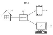
- FIG. 1 is a diagram illustrating an electric energy information provision system according to a first embodiment of the present disclosure.
- an electric energy information provision system may include a sever 20, an electricity meter, and terminals 30 and 40.
- the server 20 may be a server connectable to a network such as a cloud, but it is not limited thereto.
- the electricity meter may be installed at each of buildings 10, that is, at an indoor of each building, and measure electric energy consumed by a user of each of the buildings 10 to transmit the measured electric energy to the server 20.
- the electricity meter may be installed at an indoor usage load, but it is not limited thereto.
- the indoor usage load may be an electric home appliance, for example, a refrigerator, a washing machine, a computer and the like.
- the server 20 may generate electric energy information based on electric energy transmitted from the electricity meter of each of the buildings 10.
- the electric energy information may be a generic term for information related to various electric energy generated using measured electric energy from the electricity meter of each of the buildings 10. For example, based on the measured electric energy, electric energy information such as an electric energy variation status, a standard deviation analysis result, a dispersion variance analysis result, trend line information, past accumulative electric energy variation information, anticipated future accumulative electric energy variation information, electric energy usage status diagnosis, electric energy decreasing plan information and the like may be generated.
- electric energy information such as an electric energy variation status, a standard deviation analysis result, a dispersion variance analysis result, trend line information, past accumulative electric energy variation information, anticipated future accumulative electric energy variation information, electric energy usage status diagnosis, electric energy decreasing plan information and the like may be generated.
- the present disclosure is not limited thereto, and any kind of electric energy information to be helpful to a user may be generated.
- the terminals 30 and 40 may connect to the server 20 and receive electric energy information provided from the server 20 to display the received electric energy information.
- a display device capable of displaying electric energy information thereon may be provided at the terminals 30 and 40.
- the terminal may be a mobile terminal 30 or a fixed terminal 40.
- the mobile terminal 30 may include a mobile phone, a notebook, a tablet personal computer (PC), a watch-type terminal, a glass-type terminal and the like.
- the fixed terminal 40 may include a desk-top PC and the like.
- the terminals 30 and 40 and the server 20 may be possible to transmit and receive information to and from each other using a wireless communication.
- each of the terminals 30 and 40 and the server 20 may include a wireless communication module.
- the terminals 30 and 40 may provide the server 20 with necessary information using an input/output device.
- a user of the terminals 30 and 40 may provide the server 20 with own personal information.
- the server 20 may store the personal information or identification information of the user of the terminals 30 and 40 together with an identification number of an electricity meter installed at the building at which the user resides. Therefore, electric energy information generated based on the measured electric energy from the electricity meter may be stored together with the personal information of the user of the terminals 30 and 40.
- the server 20 may perform a user authentication based on the personal data of the user. When the user authentication is successfully performed, the server 20 may transmit the electric energy information to the terminals 30 and 40 of the user.
- FIG. 2 is a flow chart for describing an electric energy information provision method according to an embodiment of the present disclosure.
- an electricity meter installed at the building 10 measures electric energy being used therein, that is, electric energy of an indoor usage load in Operation S111.
- the electric energy may be measured in real time or in a periodical period.
- the periodical period may be once a day or once a week, but it is not limited thereto.
- the electricity meter transmits the measured electric energy to the server 20 in Operation S 114.
- the measured electric energy may be immediately transmitted to the server 20 in real time when being measured, or may be transmitted thereto in a predetermined period.
- the predetermined period may be once a day or once a week, but it is not limited thereto.
- the server 20 may analyze the transmitted electric energy to generate and analyze information related to various electric energy, that is, electric energy information in Operation S117.
- An electric energy analysis may employ a standard deviation analysis, a variance analysis, an electric energy variation analysis and the like, but it is not limited thereto.
- information related to electric energy may include an electric energy variation status, a standard deviation analysis result, a dispersion variance analysis result, trend line information, past accumulative electric energy variation information, future accumulative electric energy expected variation information, electric energy usage status diagnosis, electric energy decreasing plan information and the like, but it is not limited thereto.
- the server 20 may store the electric energy information obtained from an analysis result together with the user identification information S120.
- the user may change setting information registered at the server 20 at any time. That is, when an instruction for a setting change request is transmitted from the terminals 30 and 40 in Operation S123, the server 20 may respond to a setting change request from a user to change the preset information to a setting requested by the user. For example, when a progressive stage system is changed or an electricity unit price per time slot is changed, the user may request a setting change to a changed content using the terminals 30 and 40 at any time. According to such a setting change request of the user, the server 20 may change corresponding setting information to the setting change content requested by the user in Operation S132.
- the terminals 30 and 40 may transmit an analysis result request of the user to the server 20 in Operation S126. That is, the user may connect to the server 20 using the terminals 30 and 40 at any time to request an electric energy analysis result of the user.
- the user may connect to the server 20 using the terminals 30 and 40 through a log-in process or a user authentication process.
- a log-in process or a user authentication process When the log-in process or the user authentication process is successfully completed, electric energy information stored in the server 20 may be accessible.
- the server 20 may transmit the corresponding analysis result, that is, the electric energy information to the terminals 30 and 40 of the user based on the identification number thereof.
- the electric energy information may be displayed on a display device provided at the terminals 30 and 40 of the user in Operation S129.
- the user may easily obtain the electric energy information using the terminals 30 and 40.
- the variety of information related to the electric energy may be displayed as described above. Through displaying the variety of information, an electric energy usage custom of the user may be improved and also a reduction of electric energy of the user may be guided.
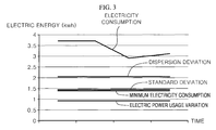
- the server 20 may generate an electricity consumption, standard deviation electric energy, dispersion deviation electric energy, a minimum electricity consumption, an electricity consumption variation on the basis of the electric energy measured at the electricity meter to provide them to the user.
- the minimum electricity consumption means lowest electricity consumption within a predetermined period. For example, when lowest electricity consumption, that is, 1.3 kWh, on March 13 th is minimum electricity consumption for one month from March 1 st to March 31 st , 1.3 kWh may be provided to the user as the minimum electricity consumption.
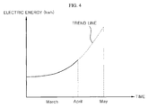
- the server 20 may generate a trend line for a future electric energy anticipated usage pattern based on the electric energy measured at the electricity meter to provide the trend line to the user.
- a trend line in May for anticipated electric energy consumption may be generated.
- a trend line in May for the anticipated electric energy consumption may be generated to be gradually increased more and more as compared to April.
- the user may recognize to reduce a usage of electric energy with reference to the trend line shown in FIG. 4 .
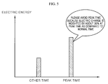
- an electric energy usage pattern of the user may be analyzed based on the measured electric energy to generate and show a graph regarding electric energy of a peak time, for example, from 2 p.m. to 5 p.m., and other time to the user. If the user may use more electric energy in the peak time as compared to the other time, message information requesting to avoid the peak time may be generated and provided to the user. As described above, the user may be helped to grasp own electric energy usage status and reduce electric charges by avoiding the peak time.
- the server 20 may analyze an electric energy usage pattern of the user to differentiate electric charges according to a progressive stage system, a peak time, a late night and the like. Consequently, a plan for reducing electric energy may be provided.
- the server 20 may compare electric energy of the buildings 10 with each other based on electric energy information of each of the buildings 10.
- the server 20 may provide information regarding the comparison result to the user. Through the comparison result, the user may easily grasp whether or not the user uses more electric energy as compared with a user of other building 10. Consequently, when using more electric energy, the user may attempt to reduce electric energy.
- the server 20 analyzes electric energy to provide the analyzed result to the user, but it is not limited thereto.
- FIG. 6 is a diagram illustrating an electric energy information provision system according to a second embodiment of the present disclosure.
- an electric energy analysis device 14 may be installed at the building 10.
- the electricity meter 12 may be installed at an indoor usage load.
- the electric energy analysis device 14 may analyze electric energy measured at the electricity meter 12 to generate and store electric energy information.
- the electric energy analysis device 14 may provide the electric energy information in response to an electric energy analysis result request of the user.
- the electric energy analysis device 14 may be capable of communicating with the server 20 to transmit the generated electric energy information thereto.
- the server 20 may store the generated electric energy information together with identification information of the user.
- the electricity meter 12 installed at the indoor usage load of the building 10 and the electric energy analysis device 14 may be referred to as an electric energy information provision apparatus.
- the electricity meter 12 and the electric energy analysis device 14 may be separately provided.
- an electric energy information provision system may be configured.
- the generated electric energy information may be transmitted to the terminals 30 and 40 to be displayed thereon.
- the terminals 30 and 40 may include a display unit for displaying the electric energy information.
- the electric energy information provision system may further include a renewable energy source and an energy storage system (hereinafter, referred to as ESS).
- ESS energy storage system
- the ESS may store energy source generated from the renewable energy source.
- the electric energy information may be generated by the electric energy analysis device 14 installed at the building 10 without being generated at the server 20.
- the electricity meter 12 and the electric energy analysis device 14 may be connected to each other through a network cable. Therefore, generation of the electric energy information of each of the buildings 10 may not be performed at the server 20 so that a load of the server 20 may be reduced. Also, the electric energy information may be generated in real time at the electric energy analysis device 14 of each of the buildings 10 so that the user may rapidly access to information. In addition, since the electric energy analysis device 14 is inside the building 10, security maintenance of the generated electric energy information may be helpful.
- an electric energy usage custom of the user may be improved and also a reduction of electric energy of the user may be guided.
Landscapes
- Engineering & Computer Science (AREA)
- Physics & Mathematics (AREA)
- General Physics & Mathematics (AREA)
- Business, Economics & Management (AREA)
- Health & Medical Sciences (AREA)
- Economics (AREA)
- Power Engineering (AREA)
- Theoretical Computer Science (AREA)
- Human Resources & Organizations (AREA)
- General Business, Economics & Management (AREA)
- Water Supply & Treatment (AREA)
- Marketing (AREA)
- Primary Health Care (AREA)
- Strategic Management (AREA)
- Tourism & Hospitality (AREA)
- General Health & Medical Sciences (AREA)
- Public Health (AREA)
- Computer Networks & Wireless Communication (AREA)
- Electromagnetism (AREA)
- Management, Administration, Business Operations System, And Electronic Commerce (AREA)
- Remote Monitoring And Control Of Power-Distribution Networks (AREA)
- Supply And Distribution Of Alternating Current (AREA)
Abstract
Description
- The present disclosure relates to an electric energy information provision system and a method thereof.
- In every building, an electricity meter is installed to indicate electric energy being currently used by digits.
- Recently, a system of displaying electric energy information over time has been proposed.
- However, such a system merely provides a user with electric energy used per hour and does not provide further information more than the electric energy, so that efficiency of an information provision is degraded.
- Therefore, an object of the present disclosure is to address the problems described above and other problems.
- Another object of the present disclosure is to provide an electric energy information provision system capable of providing a user with an effective electric energy, and a method thereof.
- In accordance with one aspect of the present disclosure to attain the objects or other objects, an electric energy information provision method includes measuring electric energy, analyzing the measured electric energy to generate electric energy information, and displaying the generated electric energy information in response to a request of a user. The electric energy information may include a variation status, a standard deviation analysis result, a dispersion deviation analysis result, trend line information, past accumulative electric energy variation information, anticipated future accumulative electric energy variation information, an electric energy usage status diagnosis, and electric energy reduction plan information.
- In accordance with another aspect of the present disclosure, an electric energy information provision system includes an electricity meter to measure electric energy, and an electric energy analysis device configured to analyze the measured electric energy to generate electric energy information and transmit the electric energy information to a user in response to a request therefrom.
- Effectiveness of a terminal according to the present disclosure is as follows.
- In accordance with at least one of the embodiments of the present disclosure, a variety of information related to electric energy may be displayed as described above instead of simply showing electric energy over time. Consequently, there are advantages in that an electric energy usage custom of a user may be improved and also a reduction of electric energy of the user may be guided.
- An additionally applicable range of the present disclosure will be apparent from the following description. However, it should be clearly understood that various modifications and alterations can be devised by those skilled in the art, and, therefore, the detailed description and specific embodiment such as the preferred embodiments of the present disclosure should be construed as illustrative embodiments thereof.
-
-
FIG. 1 is a diagram illustrating an electric energy information provision system according to a first embodiment of the present disclosure. -
FIG. 2 is a flow chart for describing an electric energy information provision method according to an embodiment of the present disclosure. -
FIG. 3 is a first exemplary diagram illustrating electric energy information. -
FIG. 4 is a second exemplary diagram illustrating electric energy information. -
FIG. 5 is a third exemplary diagram illustrating electric energy information. -
FIG. 6 is a diagram illustrating an electric energy information provision system according to a second embodiment of the present disclosure. - Hereinafter, embodiments disclosed herein will be described in detail with reference to the accompanying drawings, and the same or like components refer to the same reference numerals regardless of given reference numerals and duplicated description thereof will be omitted. In the following description, the terms of "module" and "unit" with respect to components are merely given by considering only easiness of describing the present disclosure, and these terms themselves do not represent specific meanings or functions. Also, in describing embodiments of the present disclosure described herein, if a detailed description of known functions and configurations is determined to obscure the interpretation of embodiments of the present invention, the detailed description thereof will be omitted. In addition, the accompanying drawings may be merely intended to describe the embodiments disclosed therein in an easy manner and may not represent all technical spirits of the present disclosure, and it should be construed to include numerous other modifications, equivalents and alternations within the spirit and the technical scope of the present disclosure.
-
FIG. 1 is a diagram illustrating an electric energy information provision system according to a first embodiment of the present disclosure. - With reference to
FIG. 1 , an electric energy information provision system may include asever 20, an electricity meter, andterminals server 20 may be a server connectable to a network such as a cloud, but it is not limited thereto. - The electricity meter may be installed at each of
buildings 10, that is, at an indoor of each building, and measure electric energy consumed by a user of each of thebuildings 10 to transmit the measured electric energy to theserver 20. - The electricity meter may be installed at an indoor usage load, but it is not limited thereto. The indoor usage load may be an electric home appliance, for example, a refrigerator, a washing machine, a computer and the like.
- The
server 20 may generate electric energy information based on electric energy transmitted from the electricity meter of each of thebuildings 10. - The electric energy information may be a generic term for information related to various electric energy generated using measured electric energy from the electricity meter of each of the
buildings 10. For example, based on the measured electric energy, electric energy information such as an electric energy variation status, a standard deviation analysis result, a dispersion variance analysis result, trend line information, past accumulative electric energy variation information, anticipated future accumulative electric energy variation information, electric energy usage status diagnosis, electric energy decreasing plan information and the like may be generated. - The present disclosure is not limited thereto, and any kind of electric energy information to be helpful to a user may be generated.
- The
terminals server 20 and receive electric energy information provided from theserver 20 to display the received electric energy information. For this purpose, a display device capable of displaying electric energy information thereon may be provided at theterminals - The terminal may be a
mobile terminal 30 or afixed terminal 40. Themobile terminal 30 may include a mobile phone, a notebook, a tablet personal computer (PC), a watch-type terminal, a glass-type terminal and the like. Thefixed terminal 40 may include a desk-top PC and the like. - The
terminals server 20 may be possible to transmit and receive information to and from each other using a wireless communication. For this purpose, each of theterminals server 20 may include a wireless communication module. - For example, the
terminals server 20 with necessary information using an input/output device. For instance, a user of theterminals server 20 with own personal information. Theserver 20 may store the personal information or identification information of the user of theterminals terminals server 20 using theterminals server 20 may perform a user authentication based on the personal data of the user. When the user authentication is successfully performed, theserver 20 may transmit the electric energy information to theterminals -
FIG. 2 is a flow chart for describing an electric energy information provision method according to an embodiment of the present disclosure. - With reference to
FIGS. 1 and2 , an electricity meter installed at thebuilding 10 measures electric energy being used therein, that is, electric energy of an indoor usage load in Operation S111. - The electric energy may be measured in real time or in a periodical period. Here, the periodical period may be once a day or once a week, but it is not limited thereto.
- The electricity meter transmits the measured electric energy to the
server 20 in Operation S 114. The measured electric energy may be immediately transmitted to theserver 20 in real time when being measured, or may be transmitted thereto in a predetermined period. The predetermined period may be once a day or once a week, but it is not limited thereto. - The
server 20 may analyze the transmitted electric energy to generate and analyze information related to various electric energy, that is, electric energy information in Operation S117. - An electric energy analysis may employ a standard deviation analysis, a variance analysis, an electric energy variation analysis and the like, but it is not limited thereto.
- As described above, information related to electric energy may include an electric energy variation status, a standard deviation analysis result, a dispersion variance analysis result, trend line information, past accumulative electric energy variation information, future accumulative electric energy expected variation information, electric energy usage status diagnosis, electric energy decreasing plan information and the like, but it is not limited thereto.
- The
server 20 may store the electric energy information obtained from an analysis result together with the user identification information S120. - The user may change setting information registered at the
server 20 at any time. That is, when an instruction for a setting change request is transmitted from theterminals server 20 may respond to a setting change request from a user to change the preset information to a setting requested by the user. For example, when a progressive stage system is changed or an electricity unit price per time slot is changed, the user may request a setting change to a changed content using theterminals server 20 may change corresponding setting information to the setting change content requested by the user in Operation S132. - The
terminals server 20 in Operation S126. That is, the user may connect to theserver 20 using theterminals - For example, the user may connect to the
server 20 using theterminals server 20 may be accessible. - In response to the analysis result request of the user, the
server 20 may transmit the corresponding analysis result, that is, the electric energy information to theterminals terminals - Therefore, the user may easily obtain the electric energy information using the
terminals - Hereinafter, various analysis results, that is, electric energy information which are available from the
server 20 will be described. - As shown in
FIG. 3 , theserver 20 may generate an electricity consumption, standard deviation electric energy, dispersion deviation electric energy, a minimum electricity consumption, an electricity consumption variation on the basis of the electric energy measured at the electricity meter to provide them to the user. - The minimum electricity consumption means lowest electricity consumption within a predetermined period. For example, when lowest electricity consumption, that is, 1.3 kWh, on March 13th is minimum electricity consumption for one month from March 1st to March 31st, 1.3 kWh may be provided to the user as the minimum electricity consumption.
- As shown in
FIG. 4 , theserver 20 may generate a trend line for a future electric energy anticipated usage pattern based on the electric energy measured at the electricity meter to provide the trend line to the user. - For example, on the basis of electric energy used in March and April, a trend line in May for anticipated electric energy consumption may be generated. As shown in
FIG. 4 , since the electric energy is increased in April as compared to March, a trend line in May for the anticipated electric energy consumption may be generated to be gradually increased more and more as compared to April. The user may recognize to reduce a usage of electric energy with reference to the trend line shown inFIG. 4 . - As shown in
FIG. 5 , an electric energy usage pattern of the user may be analyzed based on the measured electric energy to generate and show a graph regarding electric energy of a peak time, for example, from 2 p.m. to 5 p.m., and other time to the user. If the user may use more electric energy in the peak time as compared to the other time, message information requesting to avoid the peak time may be generated and provided to the user. As described above, the user may be helped to grasp own electric energy usage status and reduce electric charges by avoiding the peak time. - Besides the described above, the
server 20 may analyze an electric energy usage pattern of the user to differentiate electric charges according to a progressive stage system, a peak time, a late night and the like. Consequently, a plan for reducing electric energy may be provided. - Alternatively, the
server 20 may compare electric energy of thebuildings 10 with each other based on electric energy information of each of thebuildings 10. Theserver 20 may provide information regarding the comparison result to the user. Through the comparison result, the user may easily grasp whether or not the user uses more electric energy as compared with a user ofother building 10. Consequently, when using more electric energy, the user may attempt to reduce electric energy. - Heretofore, it has been described that the
server 20 analyzes electric energy to provide the analyzed result to the user, but it is not limited thereto. -
FIG. 6 is a diagram illustrating an electric energy information provision system according to a second embodiment of the present disclosure. - Instead of the
server 20, a device capable of analyzing electric energy, for example, an electricenergy analysis device 14 together with anelectricity meter 12 may be installed at thebuilding 10. - The
electricity meter 12 may be installed at an indoor usage load. - In such a case, the electric
energy analysis device 14 may analyze electric energy measured at theelectricity meter 12 to generate and store electric energy information. The electricenergy analysis device 14 may provide the electric energy information in response to an electric energy analysis result request of the user. The electricenergy analysis device 14 may be capable of communicating with theserver 20 to transmit the generated electric energy information thereto. Theserver 20 may store the generated electric energy information together with identification information of the user. - The
electricity meter 12 installed at the indoor usage load of thebuilding 10 and the electricenergy analysis device 14 may be referred to as an electric energy information provision apparatus. - On the other hand, the
electricity meter 12 and the electricenergy analysis device 14 may be separately provided. - Consequently, with the electric energy information provision apparatus and the
terminals - The generated electric energy information may be transmitted to the
terminals terminals - The electric energy information provision system may further include a renewable energy source and an energy storage system (hereinafter, referred to as ESS).
- As a renewable energy source, wind power, solar power, tidal power, or the like may be used. The ESS may store energy source generated from the renewable energy source.
- In summary, since the
electricity meter 12 and the electricenergy analysis device 14 are provided at thebuilding 10, the electric energy information may be generated by the electricenergy analysis device 14 installed at thebuilding 10 without being generated at theserver 20. Theelectricity meter 12 and the electricenergy analysis device 14 may be connected to each other through a network cable. Therefore, generation of the electric energy information of each of thebuildings 10 may not be performed at theserver 20 so that a load of theserver 20 may be reduced. Also, the electric energy information may be generated in real time at the electricenergy analysis device 14 of each of thebuildings 10 so that the user may rapidly access to information. In addition, since the electricenergy analysis device 14 is inside thebuilding 10, security maintenance of the generated electric energy information may be helpful. - In the electric energy information provision system according to the second embodiment, the disclosed contents in association with the described above and
FIGS. 2 to 5 may be directly applicable. - According to another embodiment, by displaying a variety of information related to the electric energy as described above instead of simply showing electric energy over time, an electric energy usage custom of the user may be improved and also a reduction of electric energy of the user may be guided.
- The detailed description should not be construed as limiting all aspects and should be construed as an illustration. The scope of the present disclosure should be determined by reasonably interpreting the appended claims, and all modifications within an equivalent range of the present disclosure will be included in the scope thereof.
Claims (13)
- An electric energy information provision method of providing electric energy regarding electric power used inside a building, the method comprising:measuring (S111) electric energy;analyzing (S 117) the measured electric energy to generate electric energy information; anddisplaying (S129) the generated electric energy information in response to a request of a user,wherein the generating of the electric energy information includes:generating a trend line regarding an anticipated future electric energy usage pattern based on the measured electric energy,wherein the electric energy information includes a variation status, a standard deviation analysis result, a dispersion deviation analysis result, trend line information, past accumulative electric energy variation information, anticipated future accumulative electric energy variation information, an electric energy usage status diagnosis, and electric energy reduction plan information.
- The electric energy information provision method of claim 1, further comprising:changing preset information to a setting requested by the user in response to a setting change request of the user.
- The electric energy information provision method of claim 1, wherein the generating of the electric energy information includes analyzing an electric energy usage pattern of the user based on the measured electric energy to generate electric energy of a peak time and other time.
- The electric energy information provision method of claim 3, further comprising:generating a message of requesting the user to avoid the peak time when electric energy is used more at the peak time as compared to the other time.
- An electric energy information provision system of providing electric energy regarding electric power used inside a building, the system comprising:a server 20;an indoor usage load;an electric energy analysis device 14 configured to collect electric energy information from the indoor usage load, store and analyze the collected electric energy information, and transmit the analyzed result to the server 20; andan electricity meter 12 installed in the indoor usage load to measure electric energy,wherein the electric energy analysis device 14 analyzes the measured electric energy to generate the electric energy information and provides the electric energy information to the user in response to a request therefrom, and the electric energy information includes a variation status, a standard deviation analysis result, a dispersion deviation analysis result, trend line information, past accumulative electric energy variation information, anticipated future accumulative electric energy variation information, an electric energy usage status diagnosis, and electric energy reduction plan information.
- The electric energy information provision system of claim 5, wherein the indoor usage load is an electronic home appliance.
- The electric energy information provision system of claim 5, wherein the electric energy analysis device 14 generates a trend line regarding an anticipated future electric energy usage pattern based on the measured electric energy.
- The electric energy information provision system of claim 5, wherein the electric energy analysis device 14 analyzes an electric power usage pattern of the user based on the measured electric energy to generate electric energy of a peak time and other time.
- The electric energy information provision system of claim 8, wherein the electric energy analysis device 14 generates a message of requesting the user to avoid the peak time when electric power is used more at the peak time as compared to the other time.
- The electric energy information provision system of claim 5, wherein the electric energy analysis device 14 transmits the analyzed result to terminals 30 and 40.
- The electric energy information provision system of claim 10, wherein information preset in the server 20 is changed to new setting information using the terminals 30 and 40.
- The electric energy information provision system of claim 5, further comprising:an indoor renewable energy source configured to generate indoor renewable energy; andan energy storage device configured to store the generated indoor renewable energy.
- The electric energy information provision system of claim 5, wherein the electric energy analysis device 14 includes a display unit and displays the analyzed result through the display unit.
Applications Claiming Priority (1)
| Application Number | Priority Date | Filing Date | Title |
|---|---|---|---|
| KR1020150106902A KR101977399B1 (en) | 2015-07-28 | 2015-07-28 | System of providing an electric energy information and method thereof |
Publications (1)
| Publication Number | Publication Date |
|---|---|
| EP3124984A1 true EP3124984A1 (en) | 2017-02-01 |
Family
ID=56737861
Family Applications (1)
| Application Number | Title | Priority Date | Filing Date |
|---|---|---|---|
| EP16174280.4A Ceased EP3124984A1 (en) | 2015-07-28 | 2016-06-13 | Electric energy information provision system and method thereof |
Country Status (5)
| Country | Link |
|---|---|
| US (1) | US10416207B2 (en) |
| EP (1) | EP3124984A1 (en) |
| JP (1) | JP6665052B2 (en) |
| KR (1) | KR101977399B1 (en) |
| CN (1) | CN106405183B (en) |
Families Citing this family (8)
| Publication number | Priority date | Publication date | Assignee | Title |
|---|---|---|---|---|
| JP6586076B2 (en) | 2013-03-15 | 2019-10-02 | フルークコーポレイションFluke Corporation | Visual audiovisual annotation on infrared images using a separate wireless mobile device |
| KR101977399B1 (en) * | 2015-07-28 | 2019-05-13 | 엘에스산전 주식회사 | System of providing an electric energy information and method thereof |
| WO2018176078A1 (en) * | 2017-03-31 | 2018-10-04 | Environment Partners Pty Ltd | Improvements in energy monitoring |
| US20190086453A1 (en) * | 2017-09-19 | 2019-03-21 | innogy New Ventures LLC | Method, System and Computer Program Product for Transmitting Consumption Information to a User |
| KR102294915B1 (en) * | 2020-06-01 | 2021-08-30 | 주식회사 크로센트 | ESS energy management system based on Cloud |
| CN111930018A (en) * | 2020-07-30 | 2020-11-13 | 广东电网有限责任公司东莞供电局 | Building energy management system |
| KR102820230B1 (en) * | 2022-10-12 | 2025-06-16 | 주식회사 대건소프트 | Optimal ess operation power management system using reuse battery and its method |
| KR102747059B1 (en) * | 2023-10-25 | 2024-12-26 | 정윤규 | Store environment management system |
Citations (6)
| Publication number | Priority date | Publication date | Assignee | Title |
|---|---|---|---|---|
| US20060267574A1 (en) * | 2005-04-26 | 2006-11-30 | Howard John E | Method for providing comprehensive electrical usage and demand data |
| US20070203860A1 (en) * | 2006-02-24 | 2007-08-30 | Gridpoint, Inc. | Energy budget manager |
| US20110264286A1 (en) * | 2010-04-27 | 2011-10-27 | Jong Soo Park | Smart control device |
| US20120065791A1 (en) * | 2010-09-28 | 2012-03-15 | General Electric Company | Home energy manager for providing energy projections |
| US20140201110A1 (en) * | 2013-01-17 | 2014-07-17 | Sharp Kabushiki Kaisha | Server device, electronic apparatus, communication system, and information processing method |
| US20140340075A1 (en) * | 2011-11-11 | 2014-11-20 | Sharp Kabushiki Kaisha | Power management device, method of controlling power management device, and program for controlling power management device |
Family Cites Families (53)
| Publication number | Priority date | Publication date | Assignee | Title |
|---|---|---|---|---|
| US4298839A (en) * | 1978-03-31 | 1981-11-03 | Westinghouse Electric Corp. | Programmable AC electric energy meter having radiation responsive external data interface |
| JPS61293057A (en) * | 1985-06-20 | 1986-12-23 | Shibaki Control Kk | Watthour meter with data transmitting function |
| US6366889B1 (en) * | 1998-05-18 | 2002-04-02 | Joseph A. Zaloom | Optimizing operational efficiency and reducing costs of major energy system at large facilities |
| JP2002189779A (en) | 2000-12-22 | 2002-07-05 | Tokyo Energy Research:Kk | Energy information processing system, server, energy information processing apparatus, and recording medium |
| ITMI20012726A1 (en) * | 2001-12-20 | 2003-06-20 | Enel Distribuzione Spa | SYSTEM OF REMOTE CONSUMPTION OF CONSUMPTION AND REMOTE MANAGEMENT OF USERS ALSO DISTRIBUTED OF A DOMESTIC TYPE |
| US7216021B2 (en) * | 2003-10-30 | 2007-05-08 | Hitachi, Ltd. | Method, system and computer program for managing energy consumption |
| MXPA04010077A (en) * | 2004-10-13 | 2006-05-03 | Iusa Sa De Cv | Prepayment system for electric power meters using a contactless smart card with an automatic supply cut-off device. |
| US9852486B2 (en) * | 2007-02-02 | 2017-12-26 | Aztech Associates Inc. | Utility monitoring device, system and method |
| JP4073946B1 (en) | 2007-03-30 | 2008-04-09 | 三菱電機株式会社 | Information processing device |
| KR100913125B1 (en) | 2007-09-28 | 2009-08-19 | 한국전력공사 | Power Demand Information Analysis System using Pattern Analysis and Its Method |
| US8160752B2 (en) * | 2008-09-30 | 2012-04-17 | Zome Networks, Inc. | Managing energy usage |
| KR100821825B1 (en) | 2007-12-27 | 2008-04-14 | 주식회사 케이디파워 | Power monitoring system in holistic energy management system |
| CN101354408B (en) | 2008-07-31 | 2010-08-18 | 南京能瑞自动化设备有限公司 | Electric energy acquisition and operation management system and method based on platform zone centralized service terminal |
| CN201332267Y (en) | 2008-12-31 | 2009-10-21 | 中国神华能源股份有限公司 | Electric energy monitoring system |
| KR101043828B1 (en) | 2008-12-31 | 2011-06-23 | 연세대학교 산학협력단 | Residential environment information providing system and method in home networking system |
| US8626344B2 (en) * | 2009-08-21 | 2014-01-07 | Allure Energy, Inc. | Energy management system and method |
| WO2011024366A1 (en) | 2009-08-28 | 2011-03-03 | パナソニック株式会社 | Utilization-time changing support device, and method therefor |
| KR100979410B1 (en) | 2009-10-29 | 2010-09-02 | 주식회사 한미파슨스건축사사무소 | An energy management system for house |
| KR101075958B1 (en) | 2009-11-16 | 2011-10-21 | 일진전기 주식회사 | Power exchange system of distributed generation and its method |
| KR20110070654A (en) | 2009-12-18 | 2011-06-24 | 한국전자통신연구원 | Smart energy management device for controlling power consumption and method thereof |
| US20110153101A1 (en) * | 2009-12-22 | 2011-06-23 | General Electric Company | Household energy management system and method for one or more appliances |
| JP5577717B2 (en) * | 2010-01-25 | 2014-08-27 | ソニー株式会社 | How to manage power efficiently |
| US20110218690A1 (en) * | 2010-03-05 | 2011-09-08 | Efficient Energy America Incorporated | System and method for providing automated electrical energy demand management |
| US8996184B2 (en) | 2010-05-13 | 2015-03-31 | Lsis Co., Ltd. | Apparatus and method for energy management |
| KR20110132844A (en) | 2010-06-03 | 2011-12-09 | 서울도시가스 주식회사 | Power usage consulting system and method using real-time power measurement device |
| KR101079929B1 (en) * | 2010-07-02 | 2011-11-04 | 엘에스산전 주식회사 | Energy management system of electrical equipment, energy management device of electrical equipment, energy management method of electrical equipment |
| JP2012019652A (en) * | 2010-07-09 | 2012-01-26 | Sony Corp | Apparatus and method for controlling power |
| JP2012034444A (en) | 2010-07-28 | 2012-02-16 | Toshiba Corp | Power supply-demand planning device and method thereof |
| KR101093376B1 (en) | 2010-09-03 | 2011-12-14 | 엘에스산전 주식회사 | Energy management method |
| US9292804B2 (en) * | 2010-11-25 | 2016-03-22 | Samsung Electronics Co., Ltd. | Energy management system with user interface |
| US20120166233A1 (en) * | 2010-12-22 | 2012-06-28 | Alcatel-Lucent Usa Inc. | Method And Apparatus For Enhancing Consumer Awareness Of Utility Consumption And Cost Data |
| KR101203949B1 (en) | 2011-01-27 | 2012-11-23 | 주식회사 코어세스코리아 | Power management terminal |
| KR101221097B1 (en) * | 2011-06-28 | 2013-01-11 | 주식회사 아이티스테이션 | Web based remote power information management system and method |
| KR101901230B1 (en) * | 2011-09-30 | 2018-11-06 | 삼성전자 주식회사 | Management System and Method For Electric Device, Apparatus and Portable Device supporting the same |
| JP5703207B2 (en) | 2011-12-22 | 2015-04-15 | 大和ハウス工業株式会社 | Energy management system and management device |
| CN102436731A (en) | 2011-12-23 | 2012-05-02 | 天津市电力公司 | Multi-user intelligent electric energy meter data acquisition and analysis system |
| JP5868770B2 (en) | 2012-04-26 | 2016-02-24 | 日立アプライアンス株式会社 | Usage prediction method and behavior recommendation method |
| JP6126792B2 (en) | 2012-05-07 | 2017-05-10 | トヨタホーム株式会社 | Living environment management system |
| CN202815571U (en) * | 2012-10-16 | 2013-03-20 | 惠州中城电子科技有限公司 | Electric energy information acquisition field control system |
| CN102928809B (en) | 2012-10-29 | 2015-04-08 | 江苏省电力公司常州供电公司 | Electric energy metering device remote monitoring and diagnosis system and its working method |
| KR20140077416A (en) * | 2012-12-14 | 2014-06-24 | 한국전자통신연구원 | Apparatus for predicting power usage |
| JP2014130015A (en) | 2012-12-28 | 2014-07-10 | Chugoku Electric Power Co Inc:The | Electric power meter reading/displaying system |
| KR101439257B1 (en) | 2013-02-21 | 2014-09-11 | 주식회사 유시스템 | Power consumption monitoring device and method |
| US20140316958A1 (en) * | 2013-04-17 | 2014-10-23 | Green Edge Technologies, Inc. | Systems, devices, and methods for energy account management |
| KR20140148217A (en) * | 2013-06-21 | 2014-12-31 | 한국남부발전 주식회사 | Energy management system for power plant |
| WO2015044989A1 (en) * | 2013-09-27 | 2015-04-02 | パナソニック インテレクチュアル プロパティ コーポレーション オブ アメリカ | Information provision method, information management system, and information-terminal device |
| US20150149249A1 (en) * | 2013-11-22 | 2015-05-28 | The Powerwise Group, Inc. | Methods and systems for energy arbitrage |
| CN103606018B (en) | 2013-12-04 | 2016-10-26 | 冶金自动化研究设计院 | A kind of iron and steel enterprise electric load short-term dynamic prognoses system |
| US10254319B2 (en) * | 2014-02-18 | 2019-04-09 | Encored Technologies, Inc. | Apparatus, server, system and method for energy measuring |
| KR20150128163A (en) * | 2014-05-08 | 2015-11-18 | 한국전자통신연구원 | System and method for analyzing building energy consumption information |
| KR20170097091A (en) * | 2015-01-09 | 2017-08-25 | 김영범 | Energy management system and control method thereof |
| WO2016163584A1 (en) * | 2015-04-10 | 2016-10-13 | 재단법인차세대융합기술연구원 | Location-based electric power management method and system thereof |
| KR101977399B1 (en) * | 2015-07-28 | 2019-05-13 | 엘에스산전 주식회사 | System of providing an electric energy information and method thereof |
-
2015
- 2015-07-28 KR KR1020150106902A patent/KR101977399B1/en active Active
-
2016
- 2016-06-13 EP EP16174280.4A patent/EP3124984A1/en not_active Ceased
- 2016-07-19 US US15/213,708 patent/US10416207B2/en active Active
- 2016-07-26 JP JP2016146456A patent/JP6665052B2/en not_active Expired - Fee Related
- 2016-07-26 CN CN201610597584.4A patent/CN106405183B/en active Active
Patent Citations (6)
| Publication number | Priority date | Publication date | Assignee | Title |
|---|---|---|---|---|
| US20060267574A1 (en) * | 2005-04-26 | 2006-11-30 | Howard John E | Method for providing comprehensive electrical usage and demand data |
| US20070203860A1 (en) * | 2006-02-24 | 2007-08-30 | Gridpoint, Inc. | Energy budget manager |
| US20110264286A1 (en) * | 2010-04-27 | 2011-10-27 | Jong Soo Park | Smart control device |
| US20120065791A1 (en) * | 2010-09-28 | 2012-03-15 | General Electric Company | Home energy manager for providing energy projections |
| US20140340075A1 (en) * | 2011-11-11 | 2014-11-20 | Sharp Kabushiki Kaisha | Power management device, method of controlling power management device, and program for controlling power management device |
| US20140201110A1 (en) * | 2013-01-17 | 2014-07-17 | Sharp Kabushiki Kaisha | Server device, electronic apparatus, communication system, and information processing method |
Also Published As
| Publication number | Publication date |
|---|---|
| KR20170013777A (en) | 2017-02-07 |
| KR101977399B1 (en) | 2019-05-13 |
| CN106405183B (en) | 2020-08-21 |
| JP2017033557A (en) | 2017-02-09 |
| JP6665052B2 (en) | 2020-03-13 |
| US20170030951A1 (en) | 2017-02-02 |
| CN106405183A (en) | 2017-02-15 |
| US10416207B2 (en) | 2019-09-17 |
Similar Documents
| Publication | Publication Date | Title |
|---|---|---|
| US10416207B2 (en) | Electric energy information provision system and method thereof | |
| KR101136537B1 (en) | System for measuring power using wireless personal area network | |
| US8855831B2 (en) | Energy control apparatus and method | |
| US9754329B2 (en) | Management system, smart meter, server, operation method and management method | |
| US20220261710A1 (en) | Multinodal Power Sensing, Aggregation, and Transmission | |
| JP7607594B2 (en) | Multiprocessor utility meter featuring a measurement processor connected to an application processor | |
| MX2013008640A (en) | Utility electric meter web server. | |
| US20130211614A1 (en) | Apparatus and method for controlling smart appliance using smart terminal | |
| CN104931774A (en) | An electric appliance electric quantity monitor system and a monitor method | |
| US9118153B2 (en) | Renewable energy forecasting socket | |
| KR101256946B1 (en) | Intelligent system for managing power use information | |
| KR101303321B1 (en) | Power manegement system and method using zigbee network | |
| JP2017191521A (en) | Display method, program, and display system | |
| CN106558149B (en) | A kind of intelligence electricity charge pre-storage method and system | |
| CN102288204A (en) | Energy-related information display apparatus and method thereof | |
| Kaliappan et al. | IOT Based Smart Prepaid Energy Recharge Scheme for EB | |
| KR102384424B1 (en) | Factory and building energy management system based on energy-eye | |
| Gumyusenge et al. | Design and implementation of a smart meter | |
| JP3176095U (en) | Electric power information service equipment | |
| Okafor et al. | Smart metering infrastructure for early warning demand side energy monitoring and control | |
| CN105807698A (en) | Intelligent instrument and charging monitoring system | |
| KR20160121251A (en) | Apparatus and method for predicting electricity appliance usage | |
| KR20100079287A (en) | Operation and management system for entertainment appliances by zigbee wireless communication net | |
| Sebake | Developing and testing a new generation smart meter for domestic use | |
| Rajasekaran et al. | Intelligent Energy Meter with Predictive Alerts and Security Management |
Legal Events
| Date | Code | Title | Description |
|---|---|---|---|
| PUAI | Public reference made under article 153(3) epc to a published international application that has entered the european phase |
Free format text: ORIGINAL CODE: 0009012 |
|
| STAA | Information on the status of an ep patent application or granted ep patent |
Free format text: STATUS: THE APPLICATION HAS BEEN PUBLISHED |
|
| AK | Designated contracting states |
Kind code of ref document: A1 Designated state(s): AL AT BE BG CH CY CZ DE DK EE ES FI FR GB GR HR HU IE IS IT LI LT LU LV MC MK MT NL NO PL PT RO RS SE SI SK SM TR |
|
| AX | Request for extension of the european patent |
Extension state: BA ME |
|
| STAA | Information on the status of an ep patent application or granted ep patent |
Free format text: STATUS: REQUEST FOR EXAMINATION WAS MADE |
|
| 17P | Request for examination filed |
Effective date: 20170530 |
|
| RBV | Designated contracting states (corrected) |
Designated state(s): AL AT BE BG CH CY CZ DE DK EE ES FI FR GB GR HR HU IE IS IT LI LT LU LV MC MK MT NL NO PL PT RO RS SE SI SK SM TR |
|
| STAA | Information on the status of an ep patent application or granted ep patent |
Free format text: STATUS: EXAMINATION IS IN PROGRESS |
|
| 17Q | First examination report despatched |
Effective date: 20180531 |
|
| STAA | Information on the status of an ep patent application or granted ep patent |
Free format text: STATUS: THE APPLICATION HAS BEEN REFUSED |
|
| 18R | Application refused |
Effective date: 20200215 |