EP3124849B1 - Heated connector assembly - Google Patents
Heated connector assembly Download PDFInfo
- Publication number
- EP3124849B1 EP3124849B1 EP16180238.4A EP16180238A EP3124849B1 EP 3124849 B1 EP3124849 B1 EP 3124849B1 EP 16180238 A EP16180238 A EP 16180238A EP 3124849 B1 EP3124849 B1 EP 3124849B1
- Authority
- EP
- European Patent Office
- Prior art keywords
- connector body
- connector
- heating element
- connector assembly
- fluid transfer
- Prior art date
- Legal status (The legal status is an assumption and is not a legal conclusion. Google has not performed a legal analysis and makes no representation as to the accuracy of the status listed.)
- Active
Links
Images



Classifications
-
- F—MECHANICAL ENGINEERING; LIGHTING; HEATING; WEAPONS; BLASTING
- F16—ENGINEERING ELEMENTS AND UNITS; GENERAL MEASURES FOR PRODUCING AND MAINTAINING EFFECTIVE FUNCTIONING OF MACHINES OR INSTALLATIONS; THERMAL INSULATION IN GENERAL
- F16L—PIPES; JOINTS OR FITTINGS FOR PIPES; SUPPORTS FOR PIPES, CABLES OR PROTECTIVE TUBING; MEANS FOR THERMAL INSULATION IN GENERAL
- F16L19/00—Joints in which sealing surfaces are pressed together by means of a member, e.g. a swivel nut, screwed on, or into, one of the joint parts
-
- F—MECHANICAL ENGINEERING; LIGHTING; HEATING; WEAPONS; BLASTING
- F16—ENGINEERING ELEMENTS AND UNITS; GENERAL MEASURES FOR PRODUCING AND MAINTAINING EFFECTIVE FUNCTIONING OF MACHINES OR INSTALLATIONS; THERMAL INSULATION IN GENERAL
- F16L—PIPES; JOINTS OR FITTINGS FOR PIPES; SUPPORTS FOR PIPES, CABLES OR PROTECTIVE TUBING; MEANS FOR THERMAL INSULATION IN GENERAL
- F16L53/00—Heating of pipes or pipe systems; Cooling of pipes or pipe systems
- F16L53/30—Heating of pipes or pipe systems
- F16L53/35—Ohmic-resistance heating
- F16L53/38—Ohmic-resistance heating using elongate electric heating elements, e.g. wires or ribbons
-
- F—MECHANICAL ENGINEERING; LIGHTING; HEATING; WEAPONS; BLASTING
- F16—ENGINEERING ELEMENTS AND UNITS; GENERAL MEASURES FOR PRODUCING AND MAINTAINING EFFECTIVE FUNCTIONING OF MACHINES OR INSTALLATIONS; THERMAL INSULATION IN GENERAL
- F16L—PIPES; JOINTS OR FITTINGS FOR PIPES; SUPPORTS FOR PIPES, CABLES OR PROTECTIVE TUBING; MEANS FOR THERMAL INSULATION IN GENERAL
- F16L37/00—Couplings of the quick-acting type
-
- F—MECHANICAL ENGINEERING; LIGHTING; HEATING; WEAPONS; BLASTING
- F16—ENGINEERING ELEMENTS AND UNITS; GENERAL MEASURES FOR PRODUCING AND MAINTAINING EFFECTIVE FUNCTIONING OF MACHINES OR INSTALLATIONS; THERMAL INSULATION IN GENERAL
- F16L—PIPES; JOINTS OR FITTINGS FOR PIPES; SUPPORTS FOR PIPES, CABLES OR PROTECTIVE TUBING; MEANS FOR THERMAL INSULATION IN GENERAL
- F16L43/00—Bends; Siphons
Definitions
- the present disclosure relates to a quick connector assembly and, more particularly, to a quick connector assembly with a heated connector body.
- US 2012/291904 A1 discloses a connector assembly that comprises a connector body to receive a plug, the connector body including a mechanism to retain said plug in the connector body, a conduit coupled with the connector body; and a heating element extending through the conduit and into the connector body and the plug, when said plug is retained by the connector body.
- the present disclosure enables the quick connector body and spigot to be heated from the inside of the connector assembly.
- the present disclosure provides for the power connection to be made with the connector assembly.
- a connector assembly comprises a connector body and a fluid transfer spigot received in the connector body.
- the connector body includes a mechanism to retain the spigot in the connector body.
- a fluid transfer conduit is coupled with the connector body.
- a heating element extends through the fluid transfer conduit and into the connector body and spigot. Thus, the heating element heats the connector body as well as the spigot from inside the connector assembly.
- a power wire may extend through the connector body and electrically couple with the heating element to energize the heating element.
- the heating element extends beyond a free connection end of the connector body.
- the fluid transfer conduit may have a second end coupled with a second connector body.
- the heating element extends through and beyond a free connector end of the second connector body.
- a housing may surround at least a portion of the connector body.
- the heating element extends through the connector body.
- a power wire may extend through the connector body and electrically couples with the heating element to energize the heating element.
- the heating element extends beyond a free connection end of the connector body.
- a housing surrounds at least a portion of the connector body.
- the connector assembly includes a connector body 12 and a spigot 14 received in the connector body 12.
- a housing 16 covers a portion of the connector body 12.
- An end 18 of the connector body 12 is connected, via clamp 19, with a fluid transfer conduit 20.
- a heat wire 30 as a heating element is passed through the fluid transfer conduit 20 and the connector assembly 10.
- the connector body 12 includes a mechanism 22 to retain the spigot 14 in the connector body. Seals 24 are present to seal the spigot inside the connector body 12.
- the spigot 14 may be connected to a conduit line, nozzle or the like.
- the connector body 12 has an L-shape.
- the heating wire 30 extends through the connector body 12 and into the spigot 14. The end 28 of the heating wire extends beyond the free connection end 26 of the connector body 12. Thus, the heating wire 30 heats the connector body 12 and the spigot 14 from inside of the connector assembly 10.
- a portion 32 of the heating wire 30 exits the connector body 12 via projections 31. As can be seen in FIGS. 2 and 3 , two portions 32 exit the connector body 12. The portions 32 could be adjacent one another. Each portion 32 has wires 34, 36 that are secured with the connector body 12. The wires 34, 36 may be secured in channels 35, 37. The channels 35, 37 receive connector 38 that enables the wires 34, 36 to be connected with one another or with wires 40, 42 that are connected with an electrical power source (not shown). Additionally, the wires and connections 38 may provide additional resistance heating.
- the housing 16 is of asymmetric clam shell design.
- the housing 16 includes two halves 46, 48.
- the half 46 covers a portion of the connector body 12.
- the half 48 covers the remaining portion of the connector body 12.
- the housing 46, 48 come together to form a head portion 49.
- the head portion 49 provides space for one of the connector projectors 31 and wire end portions 32.
- the housing 48 also includes a bump 50 that provides space for the other connector projection 31 and end portion 32 of the heating wire 30.
- the fluid transfer conduit 20 generally will include a pair of connector assemblies 10, one on each end of the conduit 20. Thus, only one has been illustrated.
- FIGS. 4-6 an additional embodiment is shown.
- the embodiment in FIGS. 4-6 differs from that in FIGS. 1-3 in that the connector body 112 is straight or axial and not L-shaped as in Fig. 1 . Accordingly, the same reference numerals that have been utilized in the first embodiment will be utilized in the second embodiment.
- the housing 70, surrounding the connector body 112, has a clam shell design with two halves 72, 74. Both halves 72, 74 include a bump 76, 78 that provides space for the housing projections 31 and the end portion 32 of the heated wire 30.
Landscapes
- Engineering & Computer Science (AREA)
- General Engineering & Computer Science (AREA)
- Mechanical Engineering (AREA)
- Pipe Accessories (AREA)
- Resistance Heating (AREA)
- Cooling, Air Intake And Gas Exhaust, And Fuel Tank Arrangements In Propulsion Units (AREA)
- Connector Housings Or Holding Contact Members (AREA)
- Instantaneous Water Boilers, Portable Hot-Water Supply Apparatuses, And Control Of Portable Hot-Water Supply Apparatuses (AREA)
Description
- The present disclosure relates to a quick connector assembly and, more particularly, to a quick connector assembly with a heated connector body.
- In the automobile industry, various types of quick connectors are utilized to connect ends of conduits with various elements. In some instances, heated conduit lines are desirable. In these cases, the fluid in the conduits freezes at ambient temperatures. In environments such as water lines for windshield wiper washing systems and urea solutions lines that are used in a NO reduction additives for diesel engines with SCRS catalytic converters, these types of heated conduits are desirable. Thus, it is desirable to provide a quick connector that is heatable to warm the distribution element or spigot. The present disclosure provides the art with a quick connector assembly that enables heating of the quick connector body and spigot.
US 2012/291904 A1 discloses a connector assembly that comprises a connector body to receive a plug, the connector body including a mechanism to retain said plug in the connector body, a conduit coupled with the connector body; and a heating element extending through the conduit and into the connector body and the plug, when said plug is retained by the connector body. - The present disclosure enables the quick connector body and spigot to be heated from the inside of the connector assembly. The present disclosure provides for the power connection to be made with the connector assembly.
- This object is solved by the connector assembly having the features of claim 1. According to a first object of the disclosure, a connector assembly comprises a connector body and a fluid transfer spigot received in the connector body. The connector body includes a mechanism to retain the spigot in the connector body. A fluid transfer conduit is coupled with the connector body. A heating element extends through the fluid transfer conduit and into the connector body and spigot. Thus, the heating element heats the connector body as well as the spigot from inside the connector assembly. A power wire may extend through the connector body and electrically couple with the heating element to energize the heating element. In an embodiment, the heating element extends beyond a free connection end of the connector body. The fluid transfer conduit may have a second end coupled with a second connector body. In an embodiment, the heating element extends through and beyond a free connector end of the second connector body. Also, a housing may surround at least a portion of the connector body.
- In an embodiment, the heating element extends through the connector body. A power wire may extend through the connector body and electrically couples with the heating element to energize the heating element. The heating element extends beyond a free connection end of the connector body. A housing surrounds at least a portion of the connector body.
- Further areas of applicability will become apparent from the description provided herein. The description and specific examples in this summary are intended for purposes of illustration only and are not intended to limit the scope of the present invention, which is defined by the appended claims.
- The drawings described herein are for illustrative purposes only of selected embodiments and not all possible implementations, and are not intended to limit the scope of the present invention, which is defined by the appended claims.
-
FIG. 1 is a perspective view of a connector assembly in accordance with the disclosure. -
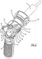
FIG. 2 is a view likeFIG. 1 with a portion of the housing removed. -
FIG. 3 is a cross-sectional view of the connector assembly ofFIG. 1 . -
FIG. 4 is a perspective view of another embodiment. -
FIG. 5 is a view likeFIG. 4 with a portion of the housing removed. -
FIG. 6 is a cross-sectional view of the connector assembly ofFIG. 4 . - Example embodiments will now be described more fully with reference to the accompanying drawings.
- Turning to the figures, a connector assembly is illustrated and designated with the
reference numeral 10. The connector assembly includes aconnector body 12 and aspigot 14 received in theconnector body 12. Ahousing 16 covers a portion of theconnector body 12. Anend 18 of theconnector body 12 is connected, viaclamp 19, with afluid transfer conduit 20. Aheat wire 30 as a heating element is passed through thefluid transfer conduit 20 and theconnector assembly 10. - The
connector body 12 includes amechanism 22 to retain thespigot 14 in the connector body.Seals 24 are present to seal the spigot inside theconnector body 12. Thespigot 14 may be connected to a conduit line, nozzle or the like. Theconnector body 12 has an L-shape. Theheating wire 30 extends through theconnector body 12 and into thespigot 14. Theend 28 of the heating wire extends beyond thefree connection end 26 of theconnector body 12. Thus, theheating wire 30 heats theconnector body 12 and thespigot 14 from inside of theconnector assembly 10. - A
portion 32 of theheating wire 30 exits theconnector body 12 viaprojections 31. As can be seen inFIGS. 2 and3 , twoportions 32 exit theconnector body 12. Theportions 32 could be adjacent one another. Eachportion 32 haswires connector body 12. Thewires channels channels connector 38 that enables thewires wires connections 38 may provide additional resistance heating. - The
housing 16 is of asymmetric clam shell design. Thehousing 16 includes twohalves connector body 12. The half 48 covers the remaining portion of theconnector body 12. Thehousing head portion 49. Thehead portion 49 provides space for one of theconnector projectors 31 andwire end portions 32. Thehousing 48 also includes abump 50 that provides space for theother connector projection 31 andend portion 32 of theheating wire 30. Thus, thehousing 16 covers theconnector body 12,wires electrical connectors 38. Thefluid transfer conduit 20 generally will include a pair ofconnector assemblies 10, one on each end of theconduit 20. Thus, only one has been illustrated. - Turning to
FIGS. 4-6 , an additional embodiment is shown. The embodiment inFIGS. 4-6 differs from that inFIGS. 1-3 in that theconnector body 112 is straight or axial and not L-shaped as inFig. 1 . Accordingly, the same reference numerals that have been utilized in the first embodiment will be utilized in the second embodiment. Thehousing 70, surrounding theconnector body 112, has a clam shell design with twohalves halves bump housing projections 31 and theend portion 32 of theheated wire 30. - The foregoing description of the embodiments has been provided for purposes of illustration and description. It is not intended to be exhaustive or to limit the disclosure. Individual elements or features of a particular embodiment are generally not limited to that particular embodiment, but, where applicable, are interchangeable and can be used in a selected embodiment, within the scope of the invention, as defined by the appended claims.
Claims (12)
- A connector assembly (10) comprising:a connector body (12, 112);a fluid transfer spigot (14) received in the connector body (12, 112), the connector body (12, 112) including a mechanism (22) to retain the fluid transfer spigot (14) in the connector body (12, 112);a fluid transfer conduit (20) coupled with the connector body (12, 112); anda heating element (30) extending through the fluid transfer conduit (20) and into the connector body (12, 112) and fluid transfer spigot (14), when the fluid transfer spigot (14) is retained by the connector body (12, 112) so that the heating element (30) heats from inside the connector assembly (10).
- The connector assembly (10) according to Claim 1, wherein a power wire (40, 42) electrically couples with the heating element (30) to energize the heating element (30).
- The connector assembly (10) according to any one of the preceding claims, wherein the heating element (30) extends beyond a free connection end (26) of the connector body (12, 112).
- The connector assembly (10) according to any one of the preceding claims, wherein the fluid transfer conduit (20) has a second end coupled with a second connector body.
- The connector assembly (10) according to any one of the preceding claims, wherein a housing (16) surrounds at least a portion of the connector body (12, 112).
- The connector assembly (10) according to Claim 4, wherein the heating element (30) extends through and beyond a free connector end of the second connector body.
- A connector assembly (10) according to Claim 1, wherein said heating element (30) extends through the connector body (12, 112).
- The connector assembly (10) according to Claim 7, wherein a power wire (40, 42) electrically couples with the heating element (30) to energize the heating element (30).
- The connector assembly (10) according to any one of Claims 7 or 8, wherein the heating element (30) extends beyond a free connection end (26) of the connector body (12, 112).
- The connector assembly (10) according to Claim 7, wherein a housing (70) surrounds at least a portion of the connector body (12, 112).
- The connector assembly (10) according to any one of Claims 7 or 8, wherein the heating element (30) includes two heating portions.
- The connector assembly (10) according to Claim 11, wherein the two heating portions both exit the connector body (12, 112) and are electrically coupled with the power wire (40, 42).
Applications Claiming Priority (2)
| Application Number | Priority Date | Filing Date | Title |
|---|---|---|---|
| US201562194434P | 2015-07-20 | 2015-07-20 | |
| US15/212,609 US20170023163A1 (en) | 2015-07-20 | 2016-07-18 | Heated Connector Assembly |
Publications (2)
| Publication Number | Publication Date |
|---|---|
| EP3124849A1 EP3124849A1 (en) | 2017-02-01 |
| EP3124849B1 true EP3124849B1 (en) | 2020-04-29 |
Family
ID=56464146
Family Applications (1)
| Application Number | Title | Priority Date | Filing Date |
|---|---|---|---|
| EP16180238.4A Active EP3124849B1 (en) | 2015-07-20 | 2016-07-19 | Heated connector assembly |
Country Status (9)
| Country | Link |
|---|---|
| US (2) | US20170023163A1 (en) |
| EP (1) | EP3124849B1 (en) |
| JP (1) | JP6764275B2 (en) |
| KR (1) | KR20170010732A (en) |
| CN (1) | CN106369240B (en) |
| BR (1) | BR102016016847B1 (en) |
| CA (1) | CA2936525A1 (en) |
| MX (1) | MX389849B (en) |
| RU (1) | RU2722197C2 (en) |
Families Citing this family (6)
| Publication number | Priority date | Publication date | Assignee | Title |
|---|---|---|---|---|
| EP3211190B1 (en) * | 2016-02-23 | 2019-04-17 | TI Automotive (Fuldabrück) GmbH | Connector assembly with at least one connector and at least one fluid line |
| DE202017101274U1 (en) * | 2017-03-06 | 2017-03-24 | TI Automotive (Fuldabrück) GmbH | Physical connection |
| EP3382255B1 (en) * | 2017-03-29 | 2019-07-03 | TI Automotive (Fuldabrück) GmbH | Pipeline comprising a connector and method for operating this pipeline |
| US11293565B2 (en) * | 2018-11-01 | 2022-04-05 | Illinois Tool Works Inc. | Pressure airlock |
| DE102019111131A1 (en) * | 2019-04-30 | 2020-11-05 | Norma Germany Gmbh | Device for connecting fluid lines and other lines |
| CN114321533A (en) * | 2021-12-24 | 2022-04-12 | 苏州恩都法汽车系统有限公司 | Multifunctional quick connector structure |
Family Cites Families (14)
| Publication number | Priority date | Publication date | Assignee | Title |
|---|---|---|---|---|
| CA2019590C (en) * | 1990-06-25 | 1994-12-06 | Lorne Heise | Self-regulating freeze-proof water protection system |
| DE19934346B4 (en) * | 1999-07-22 | 2005-10-13 | Rehau Ag + Co. | Device for fastening and sealing a heating element in a windscreen washer pipe |
| FR2905161B1 (en) * | 2006-08-25 | 2012-04-20 | Inergy Automotive Systems Res | CONNECTION WITH INTEGRATED HEATING ELEMENT. |
| JP2009002424A (en) * | 2007-06-21 | 2009-01-08 | Nitta Moore Co | Piping structure of heating and heat-retention pipe |
| JP4823980B2 (en) * | 2007-07-30 | 2011-11-24 | ニッタ株式会社 | Equipment with heating and heat insulation tubes |
| WO2009080501A1 (en) * | 2007-12-21 | 2009-07-02 | Voss Automotive Gmbh | Line connector for media lines and ready-made media line with at least one such line connector |
| JP5059631B2 (en) * | 2008-01-15 | 2012-10-24 | ニッタ株式会社 | Heating and heat insulation cover for pipe fittings |
| DE102011102151B4 (en) * | 2011-05-20 | 2022-05-19 | Norma Germany Gmbh | fluid line |
| DE102011102154A1 (en) * | 2011-05-20 | 2012-11-22 | Norma Germany Gmbh | Connector for a fluid line and fluid line |
| DE102011102244B4 (en) * | 2011-05-20 | 2014-12-31 | Norma Germany Gmbh | Connector for a heated fluid line and heated fluid line |
| CN103998845B (en) * | 2011-10-14 | 2017-11-03 | 福士汽车配套部件责任有限公司 | At least partially heatable pipe connector for a heatable media pipe and assembled media pipe with the pipe connector |
| DE102011120356A1 (en) * | 2011-12-07 | 2013-06-13 | Voss Automotive Gmbh | Prefabricated media line and method for assembling a media line with internal heating elements |
| ES2537450T3 (en) * | 2012-09-10 | 2015-06-08 | Norma Germany Gmbh | Plug-in connector |
| DE102014005817A1 (en) * | 2014-04-24 | 2015-10-29 | Voss Automotive Gmbh | Multi-part heatable media line, line connection device for such and method for producing such |
-
2016
- 2016-07-18 US US15/212,609 patent/US20170023163A1/en not_active Abandoned
- 2016-07-19 CA CA2936525A patent/CA2936525A1/en active Pending
- 2016-07-19 EP EP16180238.4A patent/EP3124849B1/en active Active
- 2016-07-19 RU RU2016129535A patent/RU2722197C2/en active
- 2016-07-19 JP JP2016141872A patent/JP6764275B2/en not_active Expired - Fee Related
- 2016-07-20 BR BR102016016847-3A patent/BR102016016847B1/en not_active IP Right Cessation
- 2016-07-20 KR KR1020160092197A patent/KR20170010732A/en not_active Abandoned
- 2016-07-20 CN CN201610574447.9A patent/CN106369240B/en not_active Expired - Fee Related
- 2016-07-20 MX MX2016009408A patent/MX389849B/en unknown
-
2020
- 2020-12-18 US US17/126,736 patent/US11536409B2/en active Active
Non-Patent Citations (1)
| Title |
|---|
| None * |
Also Published As
| Publication number | Publication date |
|---|---|
| BR102016016847B1 (en) | 2021-09-08 |
| KR20170010732A (en) | 2017-02-01 |
| US20210102653A1 (en) | 2021-04-08 |
| BR102016016847A2 (en) | 2017-12-05 |
| US11536409B2 (en) | 2022-12-27 |
| MX2016009408A (en) | 2017-06-15 |
| JP2017043346A (en) | 2017-03-02 |
| CN106369240A (en) | 2017-02-01 |
| JP6764275B2 (en) | 2020-09-30 |
| CN106369240B (en) | 2020-10-27 |
| RU2016129535A (en) | 2018-01-24 |
| CA2936525A1 (en) | 2017-01-20 |
| MX389849B (en) | 2025-03-20 |
| RU2722197C2 (en) | 2020-05-28 |
| US20170023163A1 (en) | 2017-01-26 |
| EP3124849A1 (en) | 2017-02-01 |
Similar Documents
| Publication | Publication Date | Title |
|---|---|---|
| US11536409B2 (en) | Heated connector assembly | |
| JP4708412B2 (en) | Electrically heatable cabling | |
| CN109075478B (en) | Plug connection with cooled contact elements | |
| US7857645B2 (en) | Connector arrangement for a medium-conducting, electrically-heatable hose | |
| CN109923623B (en) | A conductive contact element for an electrical plug connector | |
| US20220029329A1 (en) | Connection element for electrically connecting a fluid-coolable individual line, fluid-coolable individual line unit, and charging cable | |
| US9644776B2 (en) | Prefabricated electrically heatable media line and method for producing a media line of this kind | |
| US9890889B2 (en) | Line connector and ready-made media line | |
| US9353662B2 (en) | Fabricated media line and use in an SCR catalyst system | |
| US20110241333A1 (en) | Line Connector and Line Set for Fluid Media | |
| CN110696651B (en) | A charging terminal liquid cooling structure | |
| CN107101065B (en) | Connector assembly comprising at least one connector and at least one media line | |
| US20080202108A1 (en) | Reductant supply system for a waste gas cleaning catalyst of an internal combustion engine and a plug-in connection for connecting heatable fluid ducts | |
| US9366454B2 (en) | Heatable connection apparatus including media-conducting, electrically heatable hoses | |
| CN108692122B (en) | Pipe comprising a connector and method for operating said pipe | |
| CN111033105A (en) | Connector with a locking member | |
| CN112272744A (en) | Connecting assembly, in particular for conducting an aqueous urea solution | |
| US9920673B2 (en) | Tempered SCR-line and tempered SCR-line bundles | |
| CN207555061U (en) | heated hose | |
| KR102467977B1 (en) | Connection assembly for connecting heatable fluid lines | |
| JP2020513509A (en) | Plug connector | |
| CN116265296A (en) | Heating device for windshield wiper assembly | |
| US20210291758A1 (en) | Wire harness |
Legal Events
| Date | Code | Title | Description |
|---|---|---|---|
| PUAI | Public reference made under article 153(3) epc to a published international application that has entered the european phase |
Free format text: ORIGINAL CODE: 0009012 |
|
| STAA | Information on the status of an ep patent application or granted ep patent |
Free format text: STATUS: THE APPLICATION HAS BEEN PUBLISHED |
|
| AK | Designated contracting states |
Kind code of ref document: A1 Designated state(s): AL AT BE BG CH CY CZ DE DK EE ES FI FR GB GR HR HU IE IS IT LI LT LU LV MC MK MT NL NO PL PT RO RS SE SI SK SM TR |
|
| AX | Request for extension of the european patent |
Extension state: BA ME |
|
| STAA | Information on the status of an ep patent application or granted ep patent |
Free format text: STATUS: REQUEST FOR EXAMINATION WAS MADE |
|
| 17P | Request for examination filed |
Effective date: 20170727 |
|
| RBV | Designated contracting states (corrected) |
Designated state(s): AL AT BE BG CH CY CZ DE DK EE ES FI FR GB GR HR HU IE IS IT LI LT LU LV MC MK MT NL NO PL PT RO RS SE SI SK SM TR |
|
| STAA | Information on the status of an ep patent application or granted ep patent |
Free format text: STATUS: EXAMINATION IS IN PROGRESS |
|
| 17Q | First examination report despatched |
Effective date: 20190710 |
|
| REG | Reference to a national code |
Ref country code: DE Ref legal event code: R079 Ref document number: 602016034932 Country of ref document: DE Free format text: PREVIOUS MAIN CLASS: F16L0053000000 Ipc: F16L0053380000 |
|
| GRAP | Despatch of communication of intention to grant a patent |
Free format text: ORIGINAL CODE: EPIDOSNIGR1 |
|
| STAA | Information on the status of an ep patent application or granted ep patent |
Free format text: STATUS: GRANT OF PATENT IS INTENDED |
|
| RIC1 | Information provided on ipc code assigned before grant |
Ipc: F16L 53/38 20180101AFI20191106BHEP |
|
| INTG | Intention to grant announced |
Effective date: 20191126 |
|
| RIN1 | Information on inventor provided before grant (corrected) |
Inventor name: MOORE, GLENN Inventor name: IGNACZAK, BRIAN Inventor name: WARD, NICHOLAS |
|
| GRAS | Grant fee paid |
Free format text: ORIGINAL CODE: EPIDOSNIGR3 |
|
| GRAA | (expected) grant |
Free format text: ORIGINAL CODE: 0009210 |
|
| STAA | Information on the status of an ep patent application or granted ep patent |
Free format text: STATUS: THE PATENT HAS BEEN GRANTED |
|
| AK | Designated contracting states |
Kind code of ref document: B1 Designated state(s): AL AT BE BG CH CY CZ DE DK EE ES FI FR GB GR HR HU IE IS IT LI LT LU LV MC MK MT NL NO PL PT RO RS SE SI SK SM TR |
|
| REG | Reference to a national code |
Ref country code: GB Ref legal event code: FG4D |
|
| REG | Reference to a national code |
Ref country code: CH Ref legal event code: EP |
|
| REG | Reference to a national code |
Ref country code: DE Ref legal event code: R096 Ref document number: 602016034932 Country of ref document: DE |
|
| REG | Reference to a national code |
Ref country code: AT Ref legal event code: REF Ref document number: 1263849 Country of ref document: AT Kind code of ref document: T Effective date: 20200515 |
|
| REG | Reference to a national code |
Ref country code: IE Ref legal event code: FG4D |
|
| REG | Reference to a national code |
Ref country code: NL Ref legal event code: FP |
|
| REG | Reference to a national code |
Ref country code: SE Ref legal event code: TRGR |
|
| REG | Reference to a national code |
Ref country code: LT Ref legal event code: MG4D |
|
| PG25 | Lapsed in a contracting state [announced via postgrant information from national office to epo] |
Ref country code: GR Free format text: LAPSE BECAUSE OF FAILURE TO SUBMIT A TRANSLATION OF THE DESCRIPTION OR TO PAY THE FEE WITHIN THE PRESCRIBED TIME-LIMIT Effective date: 20200730 Ref country code: PT Free format text: LAPSE BECAUSE OF FAILURE TO SUBMIT A TRANSLATION OF THE DESCRIPTION OR TO PAY THE FEE WITHIN THE PRESCRIBED TIME-LIMIT Effective date: 20200831 Ref country code: LT Free format text: LAPSE BECAUSE OF FAILURE TO SUBMIT A TRANSLATION OF THE DESCRIPTION OR TO PAY THE FEE WITHIN THE PRESCRIBED TIME-LIMIT Effective date: 20200429 Ref country code: NO Free format text: LAPSE BECAUSE OF FAILURE TO SUBMIT A TRANSLATION OF THE DESCRIPTION OR TO PAY THE FEE WITHIN THE PRESCRIBED TIME-LIMIT Effective date: 20200729 Ref country code: IS Free format text: LAPSE BECAUSE OF FAILURE TO SUBMIT A TRANSLATION OF THE DESCRIPTION OR TO PAY THE FEE WITHIN THE PRESCRIBED TIME-LIMIT Effective date: 20200829 Ref country code: FI Free format text: LAPSE BECAUSE OF FAILURE TO SUBMIT A TRANSLATION OF THE DESCRIPTION OR TO PAY THE FEE WITHIN THE PRESCRIBED TIME-LIMIT Effective date: 20200429 |
|
| REG | Reference to a national code |
Ref country code: AT Ref legal event code: MK05 Ref document number: 1263849 Country of ref document: AT Kind code of ref document: T Effective date: 20200429 |
|
| PG25 | Lapsed in a contracting state [announced via postgrant information from national office to epo] |
Ref country code: HR Free format text: LAPSE BECAUSE OF FAILURE TO SUBMIT A TRANSLATION OF THE DESCRIPTION OR TO PAY THE FEE WITHIN THE PRESCRIBED TIME-LIMIT Effective date: 20200429 Ref country code: LV Free format text: LAPSE BECAUSE OF FAILURE TO SUBMIT A TRANSLATION OF THE DESCRIPTION OR TO PAY THE FEE WITHIN THE PRESCRIBED TIME-LIMIT Effective date: 20200429 Ref country code: BG Free format text: LAPSE BECAUSE OF FAILURE TO SUBMIT A TRANSLATION OF THE DESCRIPTION OR TO PAY THE FEE WITHIN THE PRESCRIBED TIME-LIMIT Effective date: 20200729 Ref country code: RS Free format text: LAPSE BECAUSE OF FAILURE TO SUBMIT A TRANSLATION OF THE DESCRIPTION OR TO PAY THE FEE WITHIN THE PRESCRIBED TIME-LIMIT Effective date: 20200429 |
|
| PG25 | Lapsed in a contracting state [announced via postgrant information from national office to epo] |
Ref country code: AL Free format text: LAPSE BECAUSE OF FAILURE TO SUBMIT A TRANSLATION OF THE DESCRIPTION OR TO PAY THE FEE WITHIN THE PRESCRIBED TIME-LIMIT Effective date: 20200429 |
|
| PG25 | Lapsed in a contracting state [announced via postgrant information from national office to epo] |
Ref country code: SM Free format text: LAPSE BECAUSE OF FAILURE TO SUBMIT A TRANSLATION OF THE DESCRIPTION OR TO PAY THE FEE WITHIN THE PRESCRIBED TIME-LIMIT Effective date: 20200429 Ref country code: EE Free format text: LAPSE BECAUSE OF FAILURE TO SUBMIT A TRANSLATION OF THE DESCRIPTION OR TO PAY THE FEE WITHIN THE PRESCRIBED TIME-LIMIT Effective date: 20200429 Ref country code: RO Free format text: LAPSE BECAUSE OF FAILURE TO SUBMIT A TRANSLATION OF THE DESCRIPTION OR TO PAY THE FEE WITHIN THE PRESCRIBED TIME-LIMIT Effective date: 20200429 Ref country code: ES Free format text: LAPSE BECAUSE OF FAILURE TO SUBMIT A TRANSLATION OF THE DESCRIPTION OR TO PAY THE FEE WITHIN THE PRESCRIBED TIME-LIMIT Effective date: 20200429 Ref country code: CZ Free format text: LAPSE BECAUSE OF FAILURE TO SUBMIT A TRANSLATION OF THE DESCRIPTION OR TO PAY THE FEE WITHIN THE PRESCRIBED TIME-LIMIT Effective date: 20200429 Ref country code: AT Free format text: LAPSE BECAUSE OF FAILURE TO SUBMIT A TRANSLATION OF THE DESCRIPTION OR TO PAY THE FEE WITHIN THE PRESCRIBED TIME-LIMIT Effective date: 20200429 Ref country code: DK Free format text: LAPSE BECAUSE OF FAILURE TO SUBMIT A TRANSLATION OF THE DESCRIPTION OR TO PAY THE FEE WITHIN THE PRESCRIBED TIME-LIMIT Effective date: 20200429 |
|
| REG | Reference to a national code |
Ref country code: DE Ref legal event code: R097 Ref document number: 602016034932 Country of ref document: DE |
|
| PG25 | Lapsed in a contracting state [announced via postgrant information from national office to epo] |
Ref country code: PL Free format text: LAPSE BECAUSE OF FAILURE TO SUBMIT A TRANSLATION OF THE DESCRIPTION OR TO PAY THE FEE WITHIN THE PRESCRIBED TIME-LIMIT Effective date: 20200429 Ref country code: MC Free format text: LAPSE BECAUSE OF FAILURE TO SUBMIT A TRANSLATION OF THE DESCRIPTION OR TO PAY THE FEE WITHIN THE PRESCRIBED TIME-LIMIT Effective date: 20200429 Ref country code: SK Free format text: LAPSE BECAUSE OF FAILURE TO SUBMIT A TRANSLATION OF THE DESCRIPTION OR TO PAY THE FEE WITHIN THE PRESCRIBED TIME-LIMIT Effective date: 20200429 |
|
| REG | Reference to a national code |
Ref country code: CH Ref legal event code: PL |
|
| PLBE | No opposition filed within time limit |
Free format text: ORIGINAL CODE: 0009261 |
|
| STAA | Information on the status of an ep patent application or granted ep patent |
Free format text: STATUS: NO OPPOSITION FILED WITHIN TIME LIMIT |
|
| 26N | No opposition filed |
Effective date: 20210201 |
|
| REG | Reference to a national code |
Ref country code: BE Ref legal event code: MM Effective date: 20200731 |
|
| PG25 | Lapsed in a contracting state [announced via postgrant information from national office to epo] |
Ref country code: LU Free format text: LAPSE BECAUSE OF NON-PAYMENT OF DUE FEES Effective date: 20200719 Ref country code: LI Free format text: LAPSE BECAUSE OF NON-PAYMENT OF DUE FEES Effective date: 20200731 Ref country code: CH Free format text: LAPSE BECAUSE OF NON-PAYMENT OF DUE FEES Effective date: 20200731 |
|
| PG25 | Lapsed in a contracting state [announced via postgrant information from national office to epo] |
Ref country code: BE Free format text: LAPSE BECAUSE OF NON-PAYMENT OF DUE FEES Effective date: 20200731 Ref country code: SI Free format text: LAPSE BECAUSE OF FAILURE TO SUBMIT A TRANSLATION OF THE DESCRIPTION OR TO PAY THE FEE WITHIN THE PRESCRIBED TIME-LIMIT Effective date: 20200429 |
|
| PG25 | Lapsed in a contracting state [announced via postgrant information from national office to epo] |
Ref country code: IE Free format text: LAPSE BECAUSE OF NON-PAYMENT OF DUE FEES Effective date: 20200719 |
|
| PG25 | Lapsed in a contracting state [announced via postgrant information from national office to epo] |
Ref country code: TR Free format text: LAPSE BECAUSE OF FAILURE TO SUBMIT A TRANSLATION OF THE DESCRIPTION OR TO PAY THE FEE WITHIN THE PRESCRIBED TIME-LIMIT Effective date: 20200429 Ref country code: MT Free format text: LAPSE BECAUSE OF FAILURE TO SUBMIT A TRANSLATION OF THE DESCRIPTION OR TO PAY THE FEE WITHIN THE PRESCRIBED TIME-LIMIT Effective date: 20200429 Ref country code: CY Free format text: LAPSE BECAUSE OF FAILURE TO SUBMIT A TRANSLATION OF THE DESCRIPTION OR TO PAY THE FEE WITHIN THE PRESCRIBED TIME-LIMIT Effective date: 20200429 |
|
| PG25 | Lapsed in a contracting state [announced via postgrant information from national office to epo] |
Ref country code: MK Free format text: LAPSE BECAUSE OF FAILURE TO SUBMIT A TRANSLATION OF THE DESCRIPTION OR TO PAY THE FEE WITHIN THE PRESCRIBED TIME-LIMIT Effective date: 20200429 |
|
| PGFP | Annual fee paid to national office [announced via postgrant information from national office to epo] |
Ref country code: NL Payment date: 20230726 Year of fee payment: 8 |
|
| PGFP | Annual fee paid to national office [announced via postgrant information from national office to epo] |
Ref country code: IT Payment date: 20230720 Year of fee payment: 8 Ref country code: GB Payment date: 20230727 Year of fee payment: 8 |
|
| PGFP | Annual fee paid to national office [announced via postgrant information from national office to epo] |
Ref country code: SE Payment date: 20230727 Year of fee payment: 8 Ref country code: FR Payment date: 20230725 Year of fee payment: 8 Ref country code: DE Payment date: 20230727 Year of fee payment: 8 |
|
| REG | Reference to a national code |
Ref country code: DE Ref legal event code: R119 Ref document number: 602016034932 Country of ref document: DE |
|
| REG | Reference to a national code |
Ref country code: SE Ref legal event code: EUG |
|
| REG | Reference to a national code |
Ref country code: NL Ref legal event code: MM Effective date: 20240801 |
|
| GBPC | Gb: european patent ceased through non-payment of renewal fee |
Effective date: 20240719 |
|
| PG25 | Lapsed in a contracting state [announced via postgrant information from national office to epo] |
Ref country code: DE Free format text: LAPSE BECAUSE OF NON-PAYMENT OF DUE FEES Effective date: 20250201 |
|
| PG25 | Lapsed in a contracting state [announced via postgrant information from national office to epo] |
Ref country code: NL Free format text: LAPSE BECAUSE OF NON-PAYMENT OF DUE FEES Effective date: 20240801 |
|
| PG25 | Lapsed in a contracting state [announced via postgrant information from national office to epo] |
Ref country code: FR Free format text: LAPSE BECAUSE OF NON-PAYMENT OF DUE FEES Effective date: 20240731 |
|
| PG25 | Lapsed in a contracting state [announced via postgrant information from national office to epo] |
Ref country code: GB Free format text: LAPSE BECAUSE OF NON-PAYMENT OF DUE FEES Effective date: 20240719 |
|
| PG25 | Lapsed in a contracting state [announced via postgrant information from national office to epo] |
Ref country code: IT Free format text: LAPSE BECAUSE OF NON-PAYMENT OF DUE FEES Effective date: 20240719 |
|
| PG25 | Lapsed in a contracting state [announced via postgrant information from national office to epo] |
Ref country code: SE Free format text: LAPSE BECAUSE OF NON-PAYMENT OF DUE FEES Effective date: 20240720 |