EP3124646A1 - Machine for coating an optical article and assembly and method including or carrying out this machine - Google Patents
Machine for coating an optical article and assembly and method including or carrying out this machine Download PDFInfo
- Publication number
- EP3124646A1 EP3124646A1 EP15306241.9A EP15306241A EP3124646A1 EP 3124646 A1 EP3124646 A1 EP 3124646A1 EP 15306241 A EP15306241 A EP 15306241A EP 3124646 A1 EP3124646 A1 EP 3124646A1
- Authority
- EP
- European Patent Office
- Prior art keywords
- article
- crucible
- machine
- machine according
- article holder
- Prior art date
- Legal status (The legal status is an assumption and is not a legal conclusion. Google has not performed a legal analysis and makes no representation as to the accuracy of the status listed.)
- Withdrawn
Links
- 230000003287 optical effect Effects 0.000 title claims abstract description 62
- 238000000576 coating method Methods 0.000 title claims abstract description 31
- 239000011248 coating agent Substances 0.000 title claims abstract description 29
- 238000000034 method Methods 0.000 title claims abstract description 14
- 239000008199 coating composition Substances 0.000 claims abstract description 63
- 238000001704 evaporation Methods 0.000 claims abstract description 34
- 230000008020 evaporation Effects 0.000 claims abstract description 33
- 238000000151 deposition Methods 0.000 claims abstract description 14
- 239000011521 glass Substances 0.000 claims description 6
- 238000007738 vacuum evaporation Methods 0.000 claims description 6
- 239000000203 mixture Substances 0.000 abstract description 14
- 238000009489 vacuum treatment Methods 0.000 abstract 1
- 239000007788 liquid Substances 0.000 description 20
- 239000007789 gas Substances 0.000 description 17
- 150000001875 compounds Chemical class 0.000 description 15
- 238000010438 heat treatment Methods 0.000 description 13
- 239000000463 material Substances 0.000 description 9
- 239000002318 adhesion promoter Substances 0.000 description 7
- 238000001914 filtration Methods 0.000 description 7
- 239000002904 solvent Substances 0.000 description 7
- KFZMGEQAYNKOFK-UHFFFAOYSA-N Isopropanol Chemical compound CC(C)O KFZMGEQAYNKOFK-UHFFFAOYSA-N 0.000 description 6
- 230000003373 anti-fouling effect Effects 0.000 description 6
- 125000004432 carbon atom Chemical group C* 0.000 description 6
- 230000008021 deposition Effects 0.000 description 5
- 238000013022 venting Methods 0.000 description 5
- RTZKZFJDLAIYFH-UHFFFAOYSA-N Diethyl ether Chemical compound CCOCC RTZKZFJDLAIYFH-UHFFFAOYSA-N 0.000 description 4
- 238000005304 joining Methods 0.000 description 4
- 239000010410 layer Substances 0.000 description 4
- 239000000758 substrate Substances 0.000 description 4
- OKKJLVBELUTLKV-UHFFFAOYSA-N Methanol Chemical compound OC OKKJLVBELUTLKV-UHFFFAOYSA-N 0.000 description 3
- 125000000217 alkyl group Chemical group 0.000 description 3
- 125000002947 alkylene group Chemical group 0.000 description 3
- -1 dyes Chemical class 0.000 description 3
- 125000005843 halogen group Chemical group 0.000 description 3
- 239000010702 perfluoropolyether Chemical group 0.000 description 3
- 238000012545 processing Methods 0.000 description 3
- 239000000243 solution Substances 0.000 description 3
- WYTZZXDRDKSJID-UHFFFAOYSA-N (3-aminopropyl)triethoxysilane Chemical compound CCO[Si](OCC)(OCC)CCCN WYTZZXDRDKSJID-UHFFFAOYSA-N 0.000 description 2
- SJECZPVISLOESU-UHFFFAOYSA-N 3-trimethoxysilylpropan-1-amine Chemical compound CO[Si](OC)(OC)CCCN SJECZPVISLOESU-UHFFFAOYSA-N 0.000 description 2
- 239000004593 Epoxy Substances 0.000 description 2
- LFQSCWFLJHTTHZ-UHFFFAOYSA-N Ethanol Chemical compound CCO LFQSCWFLJHTTHZ-UHFFFAOYSA-N 0.000 description 2
- 125000000738 acetamido group Chemical group [H]C([H])([H])C(=O)N([H])[*] 0.000 description 2
- BTHCBXJLLCHNMS-UHFFFAOYSA-N acetyloxysilicon Chemical compound CC(=O)O[Si] BTHCBXJLLCHNMS-UHFFFAOYSA-N 0.000 description 2
- 150000001299 aldehydes Chemical class 0.000 description 2
- 150000001336 alkenes Chemical class 0.000 description 2
- 150000001345 alkine derivatives Chemical class 0.000 description 2
- 239000006117 anti-reflective coating Substances 0.000 description 2
- 125000003178 carboxy group Chemical group [H]OC(*)=O 0.000 description 2
- 125000003262 carboxylic acid ester group Chemical group [H]C([H])([*:2])OC(=O)C([H])([H])[*:1] 0.000 description 2
- 238000004891 communication Methods 0.000 description 2
- 239000000975 dye Substances 0.000 description 2
- 125000003700 epoxy group Chemical group 0.000 description 2
- 150000002576 ketones Chemical class 0.000 description 2
- 238000011068 loading method Methods 0.000 description 2
- 239000000178 monomer Substances 0.000 description 2
- 125000006850 spacer group Chemical group 0.000 description 2
- 239000000126 substance Substances 0.000 description 2
- 125000005068 thioepoxy group Chemical group S(O*)* 0.000 description 2
- 150000003568 thioethers Chemical class 0.000 description 2
- 125000005190 thiohydroxy group Chemical group 0.000 description 2
- BPSIOYPQMFLKFR-UHFFFAOYSA-N trimethoxy-[3-(oxiran-2-ylmethoxy)propyl]silane Chemical compound CO[Si](OC)(OC)CCCOCC1CO1 BPSIOYPQMFLKFR-UHFFFAOYSA-N 0.000 description 2
- 125000000008 (C1-C10) alkyl group Chemical group 0.000 description 1
- PJURIXUDYDHOMA-UHFFFAOYSA-N 3-[tris[2-(2-methoxyethoxy)ethoxy]silyl]propan-1-amine Chemical compound COCCOCCO[Si](CCCN)(OCCOCCOC)OCCOCCOC PJURIXUDYDHOMA-UHFFFAOYSA-N 0.000 description 1
- YCKRFDGAMUMZLT-UHFFFAOYSA-N Fluorine atom Chemical compound [F] YCKRFDGAMUMZLT-UHFFFAOYSA-N 0.000 description 1
- BLRPTPMANUNPDV-UHFFFAOYSA-N Silane Chemical group [SiH4] BLRPTPMANUNPDV-UHFFFAOYSA-N 0.000 description 1
- NINIDFKCEFEMDL-UHFFFAOYSA-N Sulfur Chemical group [S] NINIDFKCEFEMDL-UHFFFAOYSA-N 0.000 description 1
- 238000005299 abrasion Methods 0.000 description 1
- 230000015572 biosynthetic process Effects 0.000 description 1
- 238000009530 blood pressure measurement Methods 0.000 description 1
- 238000006243 chemical reaction Methods 0.000 description 1
- 238000004140 cleaning Methods 0.000 description 1
- 239000011247 coating layer Substances 0.000 description 1
- 238000004590 computer program Methods 0.000 description 1
- 230000001419 dependent effect Effects 0.000 description 1
- 238000010586 diagram Methods 0.000 description 1
- 238000006073 displacement reaction Methods 0.000 description 1
- 230000000694 effects Effects 0.000 description 1
- 238000010894 electron beam technology Methods 0.000 description 1
- 125000001301 ethoxy group Chemical group [H]C([H])([H])C([H])([H])O* 0.000 description 1
- 125000001495 ethyl group Chemical group [H]C([H])([H])C([H])([H])* 0.000 description 1
- 229910052731 fluorine Inorganic materials 0.000 description 1
- 239000011737 fluorine Substances 0.000 description 1
- 229920002313 fluoropolymer Polymers 0.000 description 1
- 239000004811 fluoropolymer Substances 0.000 description 1
- 230000006870 function Effects 0.000 description 1
- 230000012447 hatching Effects 0.000 description 1
- 239000011796 hollow space material Substances 0.000 description 1
- 230000002209 hydrophobic effect Effects 0.000 description 1
- 239000012535 impurity Substances 0.000 description 1
- 229910052500 inorganic mineral Inorganic materials 0.000 description 1
- 238000010884 ion-beam technique Methods 0.000 description 1
- 239000004973 liquid crystal related substance Substances 0.000 description 1
- 239000006193 liquid solution Substances 0.000 description 1
- 125000000956 methoxy group Chemical group [H]C([H])([H])O* 0.000 description 1
- 125000002496 methyl group Chemical group [H]C([H])([H])* 0.000 description 1
- 239000011707 mineral Substances 0.000 description 1
- JXLQREJGIDQFJP-UHFFFAOYSA-N n-(3-trimethoxysilylpropyl)acetamide Chemical compound CO[Si](OC)(OC)CCCNC(C)=O JXLQREJGIDQFJP-UHFFFAOYSA-N 0.000 description 1
- 239000002105 nanoparticle Substances 0.000 description 1
- 239000011368 organic material Substances 0.000 description 1
- 125000004430 oxygen atom Chemical group O* 0.000 description 1
- 239000002245 particle Substances 0.000 description 1
- 239000004033 plastic Substances 0.000 description 1
- 229920000570 polyether Polymers 0.000 description 1
- 229920000642 polymer Polymers 0.000 description 1
- 239000013047 polymeric layer Substances 0.000 description 1
- 229920001709 polysilazane Polymers 0.000 description 1
- 229920001296 polysiloxane Polymers 0.000 description 1
- 239000002243 precursor Substances 0.000 description 1
- 125000002924 primary amino group Chemical group [H]N([H])* 0.000 description 1
- 125000001436 propyl group Chemical group [H]C([*])([H])C([H])([H])C([H])([H])[H] 0.000 description 1
- 150000004756 silanes Chemical class 0.000 description 1
- 238000009718 spray deposition Methods 0.000 description 1
- 238000003860 storage Methods 0.000 description 1
- 238000003786 synthesis reaction Methods 0.000 description 1
- TXEYQDLBPFQVAA-UHFFFAOYSA-N tetrafluoromethane Chemical group FC(F)(F)F TXEYQDLBPFQVAA-UHFFFAOYSA-N 0.000 description 1
- 231100000331 toxic Toxicity 0.000 description 1
- 230000002588 toxic effect Effects 0.000 description 1
- 239000002341 toxic gas Substances 0.000 description 1
- WEUBQNJHVBMUMD-UHFFFAOYSA-N trichloro(3,3,3-trifluoropropyl)silane Chemical compound FC(F)(F)CC[Si](Cl)(Cl)Cl WEUBQNJHVBMUMD-UHFFFAOYSA-N 0.000 description 1
- JXUKBNICSRJFAP-UHFFFAOYSA-N triethoxy-[3-(oxiran-2-ylmethoxy)propyl]silane Chemical compound CCO[Si](OCC)(OCC)CCCOCC1CO1 JXUKBNICSRJFAP-UHFFFAOYSA-N 0.000 description 1
- WFKWXMTUELFFGS-UHFFFAOYSA-N tungsten Chemical compound [W] WFKWXMTUELFFGS-UHFFFAOYSA-N 0.000 description 1
- 229910052721 tungsten Inorganic materials 0.000 description 1
- 239000010937 tungsten Substances 0.000 description 1
- 238000009834 vaporization Methods 0.000 description 1
- 230000008016 vaporization Effects 0.000 description 1
- XLYOFNOQVPJJNP-UHFFFAOYSA-N water Substances O XLYOFNOQVPJJNP-UHFFFAOYSA-N 0.000 description 1
Images


Classifications
-
- C—CHEMISTRY; METALLURGY
- C23—COATING METALLIC MATERIAL; COATING MATERIAL WITH METALLIC MATERIAL; CHEMICAL SURFACE TREATMENT; DIFFUSION TREATMENT OF METALLIC MATERIAL; COATING BY VACUUM EVAPORATION, BY SPUTTERING, BY ION IMPLANTATION OR BY CHEMICAL VAPOUR DEPOSITION, IN GENERAL; INHIBITING CORROSION OF METALLIC MATERIAL OR INCRUSTATION IN GENERAL
- C23C—COATING METALLIC MATERIAL; COATING MATERIAL WITH METALLIC MATERIAL; SURFACE TREATMENT OF METALLIC MATERIAL BY DIFFUSION INTO THE SURFACE, BY CHEMICAL CONVERSION OR SUBSTITUTION; COATING BY VACUUM EVAPORATION, BY SPUTTERING, BY ION IMPLANTATION OR BY CHEMICAL VAPOUR DEPOSITION, IN GENERAL
- C23C14/00—Coating by vacuum evaporation, by sputtering or by ion implantation of the coating forming material
- C23C14/22—Coating by vacuum evaporation, by sputtering or by ion implantation of the coating forming material characterised by the process of coating
- C23C14/24—Vacuum evaporation
-
- C—CHEMISTRY; METALLURGY
- C03—GLASS; MINERAL OR SLAG WOOL
- C03C—CHEMICAL COMPOSITION OF GLASSES, GLAZES OR VITREOUS ENAMELS; SURFACE TREATMENT OF GLASS; SURFACE TREATMENT OF FIBRES OR FILAMENTS MADE FROM GLASS, MINERALS OR SLAGS; JOINING GLASS TO GLASS OR OTHER MATERIALS
- C03C17/00—Surface treatment of glass, not in the form of fibres or filaments, by coating
- C03C17/28—Surface treatment of glass, not in the form of fibres or filaments, by coating with organic material
-
- C—CHEMISTRY; METALLURGY
- C03—GLASS; MINERAL OR SLAG WOOL
- C03C—CHEMICAL COMPOSITION OF GLASSES, GLAZES OR VITREOUS ENAMELS; SURFACE TREATMENT OF GLASS; SURFACE TREATMENT OF FIBRES OR FILAMENTS MADE FROM GLASS, MINERALS OR SLAGS; JOINING GLASS TO GLASS OR OTHER MATERIALS
- C03C17/00—Surface treatment of glass, not in the form of fibres or filaments, by coating
- C03C17/34—Surface treatment of glass, not in the form of fibres or filaments, by coating with at least two coatings having different compositions
- C03C17/3405—Surface treatment of glass, not in the form of fibres or filaments, by coating with at least two coatings having different compositions with at least two coatings of organic materials
-
- C—CHEMISTRY; METALLURGY
- C23—COATING METALLIC MATERIAL; COATING MATERIAL WITH METALLIC MATERIAL; CHEMICAL SURFACE TREATMENT; DIFFUSION TREATMENT OF METALLIC MATERIAL; COATING BY VACUUM EVAPORATION, BY SPUTTERING, BY ION IMPLANTATION OR BY CHEMICAL VAPOUR DEPOSITION, IN GENERAL; INHIBITING CORROSION OF METALLIC MATERIAL OR INCRUSTATION IN GENERAL
- C23C—COATING METALLIC MATERIAL; COATING MATERIAL WITH METALLIC MATERIAL; SURFACE TREATMENT OF METALLIC MATERIAL BY DIFFUSION INTO THE SURFACE, BY CHEMICAL CONVERSION OR SUBSTITUTION; COATING BY VACUUM EVAPORATION, BY SPUTTERING, BY ION IMPLANTATION OR BY CHEMICAL VAPOUR DEPOSITION, IN GENERAL
- C23C14/00—Coating by vacuum evaporation, by sputtering or by ion implantation of the coating forming material
- C23C14/06—Coating by vacuum evaporation, by sputtering or by ion implantation of the coating forming material characterised by the coating material
- C23C14/12—Organic material
-
- C—CHEMISTRY; METALLURGY
- C23—COATING METALLIC MATERIAL; COATING MATERIAL WITH METALLIC MATERIAL; CHEMICAL SURFACE TREATMENT; DIFFUSION TREATMENT OF METALLIC MATERIAL; COATING BY VACUUM EVAPORATION, BY SPUTTERING, BY ION IMPLANTATION OR BY CHEMICAL VAPOUR DEPOSITION, IN GENERAL; INHIBITING CORROSION OF METALLIC MATERIAL OR INCRUSTATION IN GENERAL
- C23C—COATING METALLIC MATERIAL; COATING MATERIAL WITH METALLIC MATERIAL; SURFACE TREATMENT OF METALLIC MATERIAL BY DIFFUSION INTO THE SURFACE, BY CHEMICAL CONVERSION OR SUBSTITUTION; COATING BY VACUUM EVAPORATION, BY SPUTTERING, BY ION IMPLANTATION OR BY CHEMICAL VAPOUR DEPOSITION, IN GENERAL
- C23C14/00—Coating by vacuum evaporation, by sputtering or by ion implantation of the coating forming material
- C23C14/22—Coating by vacuum evaporation, by sputtering or by ion implantation of the coating forming material characterised by the process of coating
- C23C14/50—Substrate holders
-
- C—CHEMISTRY; METALLURGY
- C23—COATING METALLIC MATERIAL; COATING MATERIAL WITH METALLIC MATERIAL; CHEMICAL SURFACE TREATMENT; DIFFUSION TREATMENT OF METALLIC MATERIAL; COATING BY VACUUM EVAPORATION, BY SPUTTERING, BY ION IMPLANTATION OR BY CHEMICAL VAPOUR DEPOSITION, IN GENERAL; INHIBITING CORROSION OF METALLIC MATERIAL OR INCRUSTATION IN GENERAL
- C23C—COATING METALLIC MATERIAL; COATING MATERIAL WITH METALLIC MATERIAL; SURFACE TREATMENT OF METALLIC MATERIAL BY DIFFUSION INTO THE SURFACE, BY CHEMICAL CONVERSION OR SUBSTITUTION; COATING BY VACUUM EVAPORATION, BY SPUTTERING, BY ION IMPLANTATION OR BY CHEMICAL VAPOUR DEPOSITION, IN GENERAL
- C23C16/00—Chemical coating by decomposition of gaseous compounds, without leaving reaction products of surface material in the coating, i.e. chemical vapour deposition [CVD] processes
- C23C16/44—Chemical coating by decomposition of gaseous compounds, without leaving reaction products of surface material in the coating, i.e. chemical vapour deposition [CVD] processes characterised by the method of coating
- C23C16/448—Chemical coating by decomposition of gaseous compounds, without leaving reaction products of surface material in the coating, i.e. chemical vapour deposition [CVD] processes characterised by the method of coating characterised by the method used for generating reactive gas streams, e.g. by evaporation or sublimation of precursor materials
- C23C16/4485—Chemical coating by decomposition of gaseous compounds, without leaving reaction products of surface material in the coating, i.e. chemical vapour deposition [CVD] processes characterised by the method of coating characterised by the method used for generating reactive gas streams, e.g. by evaporation or sublimation of precursor materials by evaporation without using carrier gas in contact with the source material
-
- C—CHEMISTRY; METALLURGY
- C23—COATING METALLIC MATERIAL; COATING MATERIAL WITH METALLIC MATERIAL; CHEMICAL SURFACE TREATMENT; DIFFUSION TREATMENT OF METALLIC MATERIAL; COATING BY VACUUM EVAPORATION, BY SPUTTERING, BY ION IMPLANTATION OR BY CHEMICAL VAPOUR DEPOSITION, IN GENERAL; INHIBITING CORROSION OF METALLIC MATERIAL OR INCRUSTATION IN GENERAL
- C23C—COATING METALLIC MATERIAL; COATING MATERIAL WITH METALLIC MATERIAL; SURFACE TREATMENT OF METALLIC MATERIAL BY DIFFUSION INTO THE SURFACE, BY CHEMICAL CONVERSION OR SUBSTITUTION; COATING BY VACUUM EVAPORATION, BY SPUTTERING, BY ION IMPLANTATION OR BY CHEMICAL VAPOUR DEPOSITION, IN GENERAL
- C23C16/00—Chemical coating by decomposition of gaseous compounds, without leaving reaction products of surface material in the coating, i.e. chemical vapour deposition [CVD] processes
- C23C16/44—Chemical coating by decomposition of gaseous compounds, without leaving reaction products of surface material in the coating, i.e. chemical vapour deposition [CVD] processes characterised by the method of coating
- C23C16/455—Chemical coating by decomposition of gaseous compounds, without leaving reaction products of surface material in the coating, i.e. chemical vapour deposition [CVD] processes characterised by the method of coating characterised by the method used for introducing gases into reaction chamber or for modifying gas flows in reaction chamber
- C23C16/45502—Flow conditions in reaction chamber
-
- G—PHYSICS
- G02—OPTICS
- G02B—OPTICAL ELEMENTS, SYSTEMS OR APPARATUS
- G02B1/00—Optical elements characterised by the material of which they are made; Optical coatings for optical elements
- G02B1/10—Optical coatings produced by application to, or surface treatment of, optical elements
-
- C—CHEMISTRY; METALLURGY
- C03—GLASS; MINERAL OR SLAG WOOL
- C03C—CHEMICAL COMPOSITION OF GLASSES, GLAZES OR VITREOUS ENAMELS; SURFACE TREATMENT OF GLASS; SURFACE TREATMENT OF FIBRES OR FILAMENTS MADE FROM GLASS, MINERALS OR SLAGS; JOINING GLASS TO GLASS OR OTHER MATERIALS
- C03C2218/00—Methods for coating glass
- C03C2218/10—Deposition methods
- C03C2218/15—Deposition methods from the vapour phase
- C03C2218/151—Deposition methods from the vapour phase by vacuum evaporation
Definitions
- the invention relates to machines for coating optical articles such as ophthalmic lenses, and in particular to machines having a vacuum chamber and an evaporation device configured to carry out in the interior space of the vacuum chamber a vacuum evaporation treatment of a coating composition for depositing the coating composition onto the optical articles.
- optical articles comprise an optical substrate having the required geometrical features, for instance for correcting the vision of the wearer if the optical article is a spectacle lens.
- the optical substrate requires the addition of coatings, for instance an anti-abrasive coating to increase the abrasion resistance of the lens, an antireflective coating to decrease the reflexion of light and an anti-soiling coating applied over the anti-reflective coating.
- coatings for instance an anti-abrasive coating to increase the abrasion resistance of the lens, an antireflective coating to decrease the reflexion of light and an anti-soiling coating applied over the anti-reflective coating.
- Some of those coatings are made from liquid compositions which have to be deposited on the optical substrate.
- the above-mentioned machines are able to carry out the deposition through vacuum evaporation of the liquid composition.
- the above mentioned machines are specifically adapted to carry out the deposition of an anti-soiling coating or an anti-fogging coating or other topcoats as a most external layer on the optical substrate.
- the invention is directed to such a machine which is efficient for coating a small number of optical articles, for instance two or even one article, while remaining simple, economic and convenient.
- the invention proposes a machine for coating an optical article, comprising:
- the housing space is at least partially above the crucible and is open towards the crucible, and since the coating composition in evaporated state leaves the crucible mostly upwards, the coating composition in evaporated state leaving the crucible passes through the housing space before going to the remainder of the interior space of the vacuum chamber.
- the concentration of the coating composition in evaporated state is thus greater in the housing space than in the remainder of the interior space and also greater than in the interior space of the vacuum chamber of the conventional machines where the coating composition goes directly in all the interior space.
- the hollow housing and the article holder are configured for locating in the housing space the optical article held by the article holder, the optical article is located in a space where the concentration of coating composition is high and therefore the optical article is coated very efficiently by the coating composition.
- the machine according to the invention does not have a miniaturized vacuum chamber. Instead, an existing (large or medium) vacuum chamber is used with the hollow housing appropriately positioned in the interior space, what is simple and economic and convenient to carry out.
- the invention is also directed, in a second aspect, to an assembly comprising a machine as disclosed above and an optical article held by the article holder of said machine.
- the optical article is a pair of glasses comprising a frame and two lenses.
- the invention is also directed, in a third aspect, to a method for coating an optical article comprising the step of providing a machine as described above, the step of holding the optical article with the article holder in the housing space and the step of carrying out with said machine a coating composition depositing cycle.
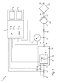
- Figure 1 shows a coating treatment machine 1 for coating an optical article 28 formed here by a spectacle lenses.
- the machine 1 comprises a vacuum chamber 8, an evaporation device 10, an inlet circuit 12, an outlet circuit 15, a vacuum pump 20 and a control unit 2.
- the vacuum chamber 8 comprises an interior space 31 configured to receive the spectacle lenses 28.
- the vacuum chamber 8 further comprises a door 9 which is removable (see description of Figures 2 and 3 below).
- the evaporation device 10 is placed in the vacuum chamber 8 (i.e. mounted on the door 9 of the vacuum chamber 8) (see below).
- the vacuum chamber 8 further comprises a first inlet port 14 and a second inlet port 34 both connected to the inlet circuit 12.
- the machine 1 further comprises a gas inlet valve 13 mounted on the inlet circuit 12 and an inlet valve 33 which is also mounted on the inlet circuit 12, parallel to the inlet valve 13.
- the vacuum chamber 8 further comprises an outlet port 16 connected to the outlet circuit 15.
- the vacuum pump 20 is connected to the outlet circuit 15 via an admission port 21 of the vacuum pump 20 and via an exit port 22 of the vacuum pump 20 so that the outlet circuit 15 passes through the vacuum pump 20.
- the machine 1 further comprises a pressure sensor 17 which is connected to the outlet circuit 15 via a branching point 18.
- the machine 1 further comprises a vacuum valve 19 which is mounted on the outlet circuit 15, between the branching point 18 and the admission port 21 of the vacuum pump 20.
- the machine 1 further comprises a filtering device 23 here formed by a gas filter.
- the filtering device 23 is connected to the outlet circuit 15 via an entrance port 24 and via an exhaust port 25 of the filtering device 23.
- the exhaust port 25 is linked to the atmosphere.
- the filtering device 23 is here mounted at the end of the outlet circuit 15, after the vacuum pump 20.
- the control unit 2 comprises a data processing system comprising a microprocessor 3 having a memory 4, in particular non volatile, allowing a software application, in other words a computer program, to be loaded and stored therein, and which allows the method for coating the spectacle lenses 28 to be carried out when it is executed in the microprocessor 3.
- a software application in other words a computer program
- the non volatile memory is for instance a read only memory.
- the data processing system further comprises a memory 5, for instance volatile, allowing storage of data during the execution of the software and the implementation of the method.
- the volatile memory 5 is for instance a random access memory or an electrically erasable programmable read only memory.
- the control unit 2 further comprises a communication interface configured to communicate with the data processing system.
- the communication interface is here formed by a graphic interface 6 and a keyboard 7.
- the control unit 2 is configured to control and exchange data with the gas inlet valves 13 and 33, the evaporation device 10, the pressure sensor 17, the vacuum valve 19 and the vacuum pump 20.
- the control unit 2 is configured to control the evaporation device 10 for carrying out with the machine 1 a coating composition depositing cycle.
- FIGS. 2 and 3 show in detail the vacuum chamber 8 and its removable door 9 respectively in an open state and in a closed state.
- the vacuum chamber 8 comprises a displacement member 26 configured for sliding the door 9 between its open and closed states.
- the machine 1 further comprises a first support 27 mounted on the interior face of the door 9.
- the first support 27 may be movable, vertically and/or longitudinally.
- the first support 27 is configured to receive a crucible 30 which is configured to be filed or imbibed with a predetermined coating liquid composition.
- the first support 27 forms a part of the evaporation device 10.
- the evaporation device 10 comprises a heating module 32 mounted on the interior face of the door 9, connected both to the first support 27 and to a power supply source (not shown) in order to heat the liquid coating composition via the crucible 30 and via the first support 27.
- the machine 1 further comprises a second support 29 which is here also mounted on the interior face of the door 9.
- the second support 29 may be movable, vertically and/or longitudinally.
- the second support 27 is configured to receive the spectacle lenses 28 mounted on the spectacle frame (see in more detail below).
- the machine 1 further comprises a hollow housing 40 surrounding a housing space 41 which is configured to be disposed above the crucible 30 and to open towards the crucible 30.
- the second support 27 is also configured to receive the hollow housing 40.
- the second support 27 may comprise at least one arm (not represented) configured to bear the hollow housing.
- the arm may be adjustable in order to place the hollow housing in a determined position relative to the crucible.
- the machine 1 further comprises an article holder 42 in the housing space 41 and the second support 27 is also configured to receive the article holder 42.
- the hollow housing 40 and the article holder 42 are configured for locating in the housing space 41 the spectacle lenses 28 held by the article holder 42.
- the open state of the door 9 enables loading of the crucible 30 imbibed with the liquid coating composition on the first support 27, and the hollow housing 40 together with the article holder 42 and the spectacle lenses 28 on the second support 29.
- the hollow housing 40 which is dome-shaped, is mounted on the second support 29 so that the vertical distance dv between the crucible 30 and the article holder 42 is between 2 and 20 times smaller than the height h of the interior space 31 of the chamber.
- the vertical distance dv between the crucible 30 and the article holder 42 is between 10 mm and 200 mm, preferably between 30 mm and 100 mm.
- the coating composition in evaporated state leaving the crucible 30 passes through the housing space 41 before going to the remainder of the interior space 31 of the vacuum chamber 8.
- the inlet opening of the housing space is remote to and above the crucible, for instance at 10 mm therefrom.
- the arrows 70 are represented in evaporation cone 80 formed by the coating composition in evaporated state when leaving the crucible.
- the evaporation cone 80 extends between the crucible 30 and the hollow housing 40 and diverges towards this latter.
- the concentration of the coating composition in evaporated state is thus greater in the housing space 41 than in the remainder of the interior space 31 and also greater than in the interior space of the vacuum chamber of the conventional machines where the coating composition goes directly in all the interior space.
- the hollow housing 40 and the article holder 42 are configured for locating in the housing space 41 the spectacle lenses 28 held by the article holder 42, the spectacle lenses 28 are located in a space where the concentration of evaporated coating composition is high and therefore the spectacle lenses 28 are coated very efficiently by the coating composition.
- the machine 1 does not have a miniaturized vacuum chamber 8. Instead, an existing (large or medium) vacuum chamber 8 is used with the hollow housing 40 appropriately positioned in the interior space 31.
- the door 9 can be moved from its open state to its closed state as shown on Figure 3 .
- the spectacles lenses 28 are here formed by a pair of glasses comprising a frame 31 and two lenses 32.
- Each lens 32 has a first surface 35 and a second surface 36 which is opposite to the first surface 35.
- the first surface 35 is for instance a concave surface of whereas the second surface 36 is for instance a convex surface.
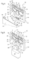
- the hollow housing 40 comprises a body 43 in which are formed the housing space 41, and a removable wall 44 which is configured to be fastened to the body 43 during the coating deposition cycle and which is further configured to be removed from the body 43 for the introduction of the spectacle lenses 28 in the housing space 41.
- the removable wall 44 comprises two lateral flanges 54 extending on the opposite sides of the removable wall 44, and two fastening edges 55 which each protrude from a respective lateral flange 54 and which face the removable wall 44.
- the body 43 comprises a main wall 45, two transverse walls 48 facing each other and each extending from the main wall 45, a lower wall 49 extending from the main wall 45 and joining both transverse walls 48, and an upper wall 53 facing the lower wall 59, extending from the main wall 45 and joining both transverse walls 48.
- the main wall 45 of the body 43 and the removable wall 44 form two main surfaces 46 and 47 of the hollow housing 40 which face each other and which are substantially parallel one another.
- the two transverse walls 48 and 49 define two transverse surfaces 58 facing each other and each extending from one the main surface 46 to the other main surface 47 in the fastened position of the removable wall 44.
- the transverse surfaces 58 are arranged as mirror images of each other.
- the removable wall 44 is configured to be fastened on the body 43 thanks to the cooperation between the two lateral flanges 54 and the two lateral walls 48 and between the two fastening edges 55 and the main wall 45.
- the hollow housing 40 is duct-shaped and comprises here one (a single) inlet opening 50 formed in the lower wall 49 of the body 43 and configured to face the crucible 30.
- the hollow housing 40 further comprises a plurality of outlet openings 52 formed in the upper wall 53, opposite to the inlet opening 50, and which face away from the crucible 30.
- the inlet opening 50 has an apparent section 51 (or an open section which is schematically represented with hatching in Figure 4 ) and is positioned so that the apparent section 51 covers at least a part of the evaporation cone 68 formed by the coating composition in evaporated state when leaving the crucible 30 ( Figure 5 ).
- the apparent section 51 covers at least the half of the evaporation cone 68, while in some embodiments, the apparent section covers between the three-quarters and the entire evaporation cone 68.
- the machine comprises 1 a protuberance 60 provided in the body 43 and extending transversely between the main surfaces 46 and 47 in the housing space 41.
- the protuberance 60 is configured to receive and maintain the optical article, for example a frame of spectacles, comprising two spectacle lenses.
- the protuberance 60 shown here is drop-shaped and comprises a top wall 80, two slope lateral walls 81 joining the top wall 82, and a curved bottom wall 83 opposite to the top wall 81 and joining the two slope lateral walls 82 ( Figure 5 ).
- the top wall 80 and the two slope lateral walls 81 form here the article holder 42; while the curved bottom wall 82 forms a flow separator 61 in the housing space 41.
- the hollow housing 41, the article holder 42 and the flow separator 61 are configured for receiving the two lenses 32 in respective predetermined locations in the housing space 41 with the flow separator 61 and more generally the protuberance 60 disposed between the respective predetermined locations.
- the article holder 42 is located between the inlet opening 50 and the plurality of outlet openings 52.
- the article holder 42 is configured for holding the pair of glasses comprising the frame 31 and the two lenses 32 and for locating the lenses 32 at mid-distance between the two main surfaces 46 and 47 of the hollow housing 40.
- the article holder 42 is configured for locating the spectacle lenses 28 held by the article holder 42 with the first and second surfaces 35 and 36 of each of the lenses 32 facing a respective one of main surfaces 46 and 47 of the hollow housing 40.
- the flow separator 61 further extends below the respective predetermined locations.
- the housing space 41 is delimited laterally by the main surfaces 46 and 47 and by the transverse surfaces 58, and is further delimited on top by the upper wall 53 and on the bottom by the lower wall 49.
- the housing space 41 has an optical article receiving portion 57 formed by the respective predetermined locations and a divergent portion 56 between the inlet opening 50 and the optical article receiving portion 57.
- the housing space 41 is configured for only receiving a small number of optical articles to be coated, for instance two or even one article; and preferably there is no place for receiving something other as the optical article(s).
- the housing space 41 has a volume between 2 and 20 times smaller than the volume of the interior space 31 of the vacuum chamber 8; and preferably the housing space 41 has a volume between 300 and 600 cm 3 .
- the hollow housing and the article holder are here formed as a single piece made for instance from plastic material.
- Figure 5 shows the path for the coating composition in evaporated state, from the crucible 30 in the evaporation cone 68 to the remainder of the interior space 31 of the vacuum chamber 8, by passing through the hollow space 41.
- the coating composition in evaporated state follows the arrows 70. More precisely, the coating composition in evaporated state enters in the housing space 41 by the apparent section 51 of the inlet opening 50, next successively flows along the divergent portion 56 and along the optical article receiving portion 57, where the coating composition in evaporated state is separated by the flow separator 61 and reaches both the first and second surfaces 35 and 36 of the two lenses 32 disposed in the respective predetermined locations.
- Such flow is enabled by the geometry of the hollow housing and in particular by the cooperation of the flow separator 61, the transverses surfaces 58 and both the main wall 45 and the removable wall 44.
- the coating composition in evaporated state is directed toward both sides of the optical lenses.
- the flow separator 61 and/or one of the walls 45 or 44 may be arranged to have a flow regulator that directs the coating composition in evaporated state mainly toward one side of each optical lens.
- the coating composition in evaporated state flows out from the housing space 41 by the plurality of outlet openings 52 and enters in the remainder of the interior space 31 of the vacuum chamber 8.
- the method comprises the step 100 of providing the machine 1 as described above, including the hollow housing 40 and the article holder 42, spectacle lenses 28 and the crucible 30 previously filed or imbibed with a predetermined liquid coating composition to deposit.
- the method comprises the step 101 of holding the spectacle lenses 28 with the article holder 42 in the housing space 41, thanks to the protuberance 60, and of loading the hollow housing 40 and the crucible 30 in the vacuum chamber 8.
- the removable wall 44 of the hollow housing 40 is removed from the body 43, allowing a free access to the housing space 41.
- the spectacle lenses 28 are located in the housing space 41, each lens 32 being housed in the respective predetermined location, from either sides of the protuberance 60.
- the spectacle lenses 28 are thus disposed between the inlet opening 50 and the outlet openings 52.
- the removable wall 44 is then mounted and preferably fastened on the body 43.
- the user opens the door 9 of the vacuum chamber 8 and loads the crucible 30 and the hollow housing 40 respectively on the first support 27 and on the second support 29.
- the user closes the door 9 of the vacuum chamber 8.
- the user starts the treatment program for coating the spectacle lenses 28 via the keyboard 7 and the graphic interface 6.
- the control unit 2 then takes over the coating treatment.
- the vacuum pump 20 is started at step 102 and the vacuum valve 19 is opened at step 104 in order to connect (a flow connection) the vacuum pump 20 to the vacuum chamber 8 for evacuating the interior space 31 of the vacuum chamber 8 via the outlet circuit 15.
- the vacuum pump 20 is thus able to suck the gases from the vacuum chamber 8.
- the control unit 2 is configured to control the pressure (he waits and takes pressure measurements) in the vacuum chamber 8 via the pressure sensor 17 until the vacuum chamber pressure reaches a predetermined pressure value, for instance about 50 mbar.
- step 103 the gas inlet valve 13 is opened in order to allow gas to enter in the vacuum chamber 8 via the inlet circuit 12 to have a stable pressure in the vacuum chamber 8.
- the gas is here atmospheric air.
- the inlet valve 13 is then closed to end the venting step 103.
- the venting step 103 can be carried out before or after the step 104 of opening the vacuum valve 19.
- the vacuum valve 19 is then closed at step 105 in order to disconnect (a flow interruption) the vacuum pump 20 from the vacuum chamber 8.
- the vacuum pump 20 is thus able not to suck the gases from the vacuum chamber 8.
- the heating module 32 of the evaporation device 10 is then setting at step 106 for a predetermined time at a predetermined current in order to reach a predetermined temperature of the heating module 32.
- the predetermined time is for instance about 30 to 50 s and the predetermined heating temperature is about 350 °C. Heat time and temperature are dependent on evaporation pressure and precursor used.
- the heat of the heating module 32 is at least partially transferred to the crucible 30 and thus to the coating liquid composition.
- the heating step is stopped and the evaporation treatment continues (step 106) for a predetermined time which is for instance equal to 60 to 180 s.
- the coating composition is evaporated and leaves the crucible 30 mostly upwards, in the evaporation cone 68, so that the coating composition in evaporated state:
- the vapour is first deposited on the spectacle lenses 28 and next the remainder of the vapour reaches the remainder of the interior space 31 of the vacuum chamber 8.
- the vacuum valve 19 is opened at step 107 in order to reconnect (a flow connection) the vacuum pump 20 to the vacuum chamber 8 for evacuating the vacuum chamber 8, and in particular for evacuating the gases emitted during the vacuum evaporation treatment because such gases might be toxic.
- the vacuum pump 20 is thus able to suck the gases from the vacuum chamber 8.
- the gases are sent from the vacuum pump 20 to the filtering device 23 where the gases are filtered at step 108.
- the filtering step 108 is carried out for a predetermined time, for instance about 120 s.
- the vacuum valve 19 is then closed at step 109 so that the vacuum pump 20 is disconnected (a flow interruption) from the vacuum chamber 8.
- the vacuum pump 20 is thus able not to suck the gases from the vacuum chamber 8.
- a venting step 110 is carried out for equilibrating the chamber pressure with atmospheric pressure.
- the venting step 110 is identical to the venting step 103.
- the gas inlet valve 33 is opened for a predetermined time, for instance 60 s, in order to vent the vacuum chamber 8 and the gas inlet valve 33 is then closed.
- the coating treatment is thus finished and the user opens the door 9 of the vacuum chamber 8.
- the user unloads the hollow housing 40 including the spectacle lenses 28 which are coated with the predetermined coating composition, and the crucible 30.
- the liquid coating composition has been consumed and the crucible 30 may be a disposable product.
- the user may wash the spectacle lenses 28 with a cleaning solution, such as IPA ("isopropyl alcohol or isopropanol").
- IPA isopropyl alcohol or isopropanol
- the predetermined coating composition might be a top coat.
- Such a topcoat might be a polymeric layer that can be deposited in order to improve the deposition performances of a topcoat layer.
- a topcoat layer might be a polymeric layer that can be deposited in order to improve the deposition performances of a topcoat layer.
- one desires to deposit such topcoat on top of a lens surface of unknown origin one may need the deposition of an universal adhesion layer.
- the topcoat may be a complex hybrid compound, comprising for instance metallic or mineral particles or nanoparticles. It might comprise monomers or mix of monomers in order to form polymeric materials. It might even comprise active compounds such as dyes, photochromic dyes, electrochromic materials, liquid crystals...etc.
- the topcoat may be one of an antifouling composition, an anti-fog composition or a bond coat, which can be used to prepare the surface of the lenses before receiving either an antifouling composition or an anti-fog composition.
- the bond coat that may be interposed between the outermost coating and the topcoat comprises at least one adhesion promoter.
- this adhesion promoter comprises, and preferably consists in, (i) a -SiXYZ head group, wherein X, Y and Z are independently chosen from an halogen atom or an - OR group wherein each R is independently a linear alkyl having from 1 to 6 carbon atoms or a branched alkyl having from 3 to 6 carbon atoms, (ii) a reactive end group which is able to react, optionally after a physical, chemical or physic-chemical treatment, with at least one function carried by at least one compound included in a topcoat composition, and (iii) a spacer that links the head and end groups.
- the reactive end group is preferably any of the following groups: amino, hydroxyl, thiohydroxy, acetamido, halogeno, halogenosilane, alcoxysilane, acetoxysilane, epoxy, thioepoxy, aldehyde, alkyne, carboxyl or a group which may be converted into one of those by chemical reaction, for instance an ether, thioether, alkene, ketone or carboxylic acid ester group.
- the adhesion promoter is preferably such that at least one, and preferably all, the following conditions are satisfied:
- the adhesion promoter may have a molecular weight between 150 and 1000 g/mol and preferably between 165 and 450 g/mol.
- adhesion promoters are 3-amino-propyltrimethoxysilane (APTMS), 3-aminopropyltriethoxysilane (APTES), 3-aminopropyl-tris(methoxyethoxyethoxy) silane, acetamido propyltrimethoxysilane, ⁇ -glycidoxypropyl trimethoxysilane (GLYMO), ⁇ -glycidoxypropyltriethoxysilane, and mixtures thereof.
- APIMS 3-amino-propyltrimethoxysilane
- APTES 3-aminopropyltriethoxysilane
- GLYMO ⁇ -glycidoxypropyl trimethoxysilane
- the bond coat usually consists in the adhesion promoter, and does not contain any other compound besides the impurities optionally present in the adhesion promoter as a result of its synthesis.
- the bond coat generally has a thickness ranging from 1 nm to 100 nm.
- the bond coat composition may be applied onto the outermost organic coating by vacuum evaporation or by spray deposition.
- Various evaporation devices can be used in accordance with the process of the invention, such as devices based on ion or electron beam heating methods, devices based on highfrequency heating method, devices based on optical heating method (for example such device comprising a tungsten lamp), a Joule effect device or resistance heating device, and more generally any heating device which provides sufficient heat to evaporate the liquid coating material.
- Those devices are well known in the art.
- the anti-fouling top coats preferably used in this invention are those which reduce surface energy of the optical article to less than 14 mJ/m 2 .
- the invention has a particular interest when using anti-fouling topcoats having a surface energy of less than 13 mJ/m 2 and even better less than 12 mJ/m 2 .
- These surface energy values are calculated according to Owens Wendt method described in the following document: Owens, D. K.; Wendt, R. G. "Estimation of the surface force energy of polymers", J. Appl. Polym. Sci. 1969, 51, 1741-1747 .
- the anti-fouling top coat according to the invention is preferably of organic nature.
- organic nature it is meant a layer which is comprised of at least 40% by weight, preferably at least 50% by weight of organic materials, relative to the total weight of the coating layer.
- a preferred anti-fouling top coat is made from a liquid coating material comprising at least one fluorinated compound, bearing in particular perfluorocarbon or perfluoropolyether group(s).
- silazane, polysilazane or silicone compounds are to be mentioned, comprising one or more fluorine-containing groups such as those mentioned here above.
- Such compounds have been widely disclosed in the previous art, for example in Patents US 4 410 563 , EP 0 203 730 , EP 0 749 021 , EP 0 844 265 and EP 0 933 377 .
- Preferred fluorinated compounds are silanes and silazanes bearing at least one group selected from fluorinated hydrocarcarbons, perfluorocarbons, fluorinated polyethers such as F 3 C-(OC 3 F 6 ) 24 -O-(CF 2 ) 2 -(CH 2 ) 2 -O-CH 2 -Si(OCH 3 ) 3 and perfluoropolyethers, in particular perfluoropolyethers.
- compositions containing fluorinated compounds also useful for making hydrophobic and/or oleophobic top coats are disclosed in US 6,183,872 .
- the silicon- containing organic fluoropolymer of US 6,183,872 is represented by the below general formula and has a number average molecular weight of from 5.10 2 to 1.105.
- the predetermined liquid coating composition to be deposited may be any liquid solution. In some cases, it is useful to provide the needed compounds in a solvent: for instance water, or ethanol, or methanol, or HFE7100 or other solvents.
- the predetermined liquid coating composition has for instance a concentration of compound into the solvent which might vary from 0,1% up till 100%.
- the predetermined liquid coating composition has a concentration of compound vs. solvent which depend on the viscosity of solvent and compound and/or of the vaporization pressure at ambient temperature of the solvent.
- the viscosity of the predetermined liquid coating composition to be evaporated might depend on the solvent used if any.
- the necessary volume of predetermined coating composition may vary depending on the final thickness of material needed, the concentration of material in the solution, the concentration of compound in the solution.
- the article holder and the hollow housing are not formed as a single piece, and the hollow housing is distinct to the article holder.
- the article holder is not formed by a protuberance provided in the body of the hollow housing, as described above.
- the hollow housing is dome-shaped and is mounted on the second support; while the article holder is a plate located in the housing space and maintained in position therein thanks to a dedicated support of the machine or thanks to a supporting member formed in the hollow housing.
Landscapes
- Chemical & Material Sciences (AREA)
- Organic Chemistry (AREA)
- Engineering & Computer Science (AREA)
- Chemical Kinetics & Catalysis (AREA)
- Materials Engineering (AREA)
- Metallurgy (AREA)
- Mechanical Engineering (AREA)
- General Chemical & Material Sciences (AREA)
- Physics & Mathematics (AREA)
- Geochemistry & Mineralogy (AREA)
- Life Sciences & Earth Sciences (AREA)
- General Physics & Mathematics (AREA)
- Optics & Photonics (AREA)
- Eyeglasses (AREA)
- Physical Vapour Deposition (AREA)
- Surface Treatment Of Optical Elements (AREA)
Abstract
Description
- The invention relates to machines for coating optical articles such as ophthalmic lenses, and in particular to machines having a vacuum chamber and an evaporation device configured to carry out in the interior space of the vacuum chamber a vacuum evaporation treatment of a coating composition for depositing the coating composition onto the optical articles.
- It is well known that optical articles comprise an optical substrate having the required geometrical features, for instance for correcting the vision of the wearer if the optical article is a spectacle lens.
- The optical substrate requires the addition of coatings, for instance an anti-abrasive coating to increase the abrasion resistance of the lens, an antireflective coating to decrease the reflexion of light and an anti-soiling coating applied over the anti-reflective coating.
- Some of those coatings are made from liquid compositions which have to be deposited on the optical substrate. The above-mentioned machines are able to carry out the deposition through vacuum evaporation of the liquid composition. The above mentioned machines are specifically adapted to carry out the deposition of an anti-soiling coating or an anti-fogging coating or other topcoats as a most external layer on the optical substrate.
- Such machines in which the coating composition in evaporated state leaves the evaporation device from a crucible are already known, for instance from
French patent application 2 775 298United States Patent US 6,375,747 or fromEuropean .Patent Application EP 2 548 991 - The invention is directed to such a machine which is efficient for coating a small number of optical articles, for instance two or even one article, while remaining simple, economic and convenient.
- To this end, the invention proposes a machine for coating an optical article, comprising:
- a vacuum chamber having an interior space configured to receive said optical article; and
- an evaporation device configured to carry out a vacuum evaporation treatment of a coating composition for depositing the coating composition onto said optical article in said interior space, said evaporation device comprising in the interior space a crucible from which the coating composition in evaporated state leaves the evaporation device;
characterized in that the machine comprises in the interior space a hollow housing surrounding a housing space which is at least partially above the crucible and open towards the crucible, and the machine comprises in the housing space an article holder, the hollow housing and the article holder being configured for locating in the housing space the optical article held by the article holder. - Since the housing space is at least partially above the crucible and is open towards the crucible, and since the coating composition in evaporated state leaves the crucible mostly upwards, the coating composition in evaporated state leaving the crucible passes through the housing space before going to the remainder of the interior space of the vacuum chamber.
- The concentration of the coating composition in evaporated state is thus greater in the housing space than in the remainder of the interior space and also greater than in the interior space of the vacuum chamber of the conventional machines where the coating composition goes directly in all the interior space.
- Since the hollow housing and the article holder are configured for locating in the housing space the optical article held by the article holder, the optical article is located in a space where the concentration of coating composition is high and therefore the optical article is coated very efficiently by the coating composition.
- In addition, for a given thickness of material deposited on the optical article, there is less coating composition deposited on the inner surfaces of the vacuum chamber and therefore less fouling of the vacuum chamber and less losses of the coating composition. Indeed, less coating composition in the crucible is needed to be evaporated in order to coat the optical article as compared to other machines without hollow housing as described above.
- The machine according to the invention does not have a miniaturized vacuum chamber. Instead, an existing (large or medium) vacuum chamber is used with the hollow housing appropriately positioned in the interior space, what is simple and economic and convenient to carry out.
- According to advantageous features:
- the vertical distance between the crucible and the article holder is between 2 and 20 times smaller than the height of the interior space; and/or
- the vertical distance between the crucible and the article holder is between 10 and 25 cm.
- According to advantageous features:
- the hollow housing is dome-shaped;
- the hollow housing is duct-shaped with at least one inlet opening and at least one outlet opening, the inlet opening facing the crucible, the article holder being located between the inlet opening and the outlet opening;
- the at least one inlet opening has an apparent section and is positioned so that the apparent section covers a part of an evaporation cone formed by the coating composition in evaporated state when leaving the crucible; for instance, the apparent section may cover more than the half of the evaporation cone, preferably between three quarts and all of the evaporation cone.
- the outlet opening faces away from the crucible;
- the hollow housing has a plurality of said outlet openings;
- the hollow housing comprises two main surfaces facing each other and the article holder is configured for locating the optical article held by the article holder with each main face of the optical article facing a respective one of said main surfaces;
- the article holder is configured for locating the optical article held by the article holder at mid-distance between the two main surfaces;
- the main surfaces are substantially parallel one another;
- one of said main surfaces belongs to a removable wall;
- the hollow housing comprises two transverse surfaces facing each other and each extending from one of the main surfaces to the other of the main surfaces, the housing space being delimited laterally by the main surfaces and by the transverse surfaces;
- the transverse surfaces are arranged as mirror images of each other;
- the housing space has a divergent portion between an inlet opening and an optical article receiving portion;
- the machine comprises in the housing space a flow separator and the hollow housing, the article holder and the flow separator are configured for receiving two lenses in respective predetermined locations in the housing space with the flow separator disposed between the respective predetermined locations;
- the flow separator extends below the respective predetermined locations;
- the article holder and the flow separator are formed by a protuberance extending transversely between the main surfaces;
- the housing space is configured for only receiving a small number of optical articles to be coated, for instance two or even one article; and preferably there is no place for receiving something other as the optical article(s);
- the housing space has a volume between 2 and 20 times smaller than the volume of the interior space of the vacuum chamber;
- the housing space has a volume between 300 and 600 cm3; and/or
- the article holder is configured for holding a pair of glasses comprising a frame and two lenses.
- The invention is also directed, in a second aspect, to an assembly comprising a machine as disclosed above and an optical article held by the article holder of said machine.
- Preferably, the optical article is a pair of glasses comprising a frame and two lenses.
- The invention is also directed, in a third aspect, to a method for coating an optical article comprising the step of providing a machine as described above, the step of holding the optical article with the article holder in the housing space and the step of carrying out with said machine a coating composition depositing cycle.
- The description of the invention now continues with a detailed description of preferred embodiments given hereinafter by way of non-limiting example and with reference to the appended drawings. In these drawings:
-
Figure 1 is a schematic view of a system for coating according to the invention; -
Figures 2 and 3 are partially schematic views of the system showing in particular a vacuum chamber, an optical article to be coated, a crucible containing a coating composition, a hollow housing and an article holder which are configured for locating in a housing space the optical article held by the article holder, and a door of the chamber being respectively open and closed; -
Figure 4 represents in more detail the housing space, the hollow housing and the article holder, which are shown schematically and partially in perspective; -
Figure 5 is a similar view asFigure 4 , showing the way of the coating composition in evaporated state in the housing space; and -
Figure 6 is a block diagram illustrating steps for using the system for coating the optical article according to an embodiment. -
Figure 1 shows a coating treatment machine 1 for coating anoptical article 28 formed here by a spectacle lenses. - The machine 1 comprises a
vacuum chamber 8, anevaporation device 10, aninlet circuit 12, anoutlet circuit 15, avacuum pump 20 and acontrol unit 2. - The
vacuum chamber 8 comprises aninterior space 31 configured to receive thespectacle lenses 28. - The
vacuum chamber 8 further comprises adoor 9 which is removable (see description ofFigures 2 and 3 below). - The
evaporation device 10 is placed in the vacuum chamber 8 (i.e. mounted on thedoor 9 of the vacuum chamber 8) (see below). - The
vacuum chamber 8 further comprises afirst inlet port 14 and asecond inlet port 34 both connected to theinlet circuit 12. - The machine 1 further comprises a
gas inlet valve 13 mounted on theinlet circuit 12 and aninlet valve 33 which is also mounted on theinlet circuit 12, parallel to theinlet valve 13. - The
vacuum chamber 8 further comprises anoutlet port 16 connected to theoutlet circuit 15. - The
vacuum pump 20 is connected to theoutlet circuit 15 via anadmission port 21 of thevacuum pump 20 and via anexit port 22 of thevacuum pump 20 so that theoutlet circuit 15 passes through thevacuum pump 20. - The machine 1 further comprises a
pressure sensor 17 which is connected to theoutlet circuit 15 via a branchingpoint 18. - The machine 1 further comprises a
vacuum valve 19 which is mounted on theoutlet circuit 15, between the branchingpoint 18 and theadmission port 21 of thevacuum pump 20. - The machine 1 further comprises a
filtering device 23 here formed by a gas filter. - The
filtering device 23 is connected to theoutlet circuit 15 via anentrance port 24 and via anexhaust port 25 of thefiltering device 23. - The
exhaust port 25 is linked to the atmosphere. - The
filtering device 23 is here mounted at the end of theoutlet circuit 15, after thevacuum pump 20. - The
control unit 2 comprises a data processing system comprising a microprocessor 3 having a memory 4, in particular non volatile, allowing a software application, in other words a computer program, to be loaded and stored therein, and which allows the method for coating thespectacle lenses 28 to be carried out when it is executed in the microprocessor 3. - The non volatile memory is for instance a read only memory.
- The data processing system further comprises a memory 5, for instance volatile, allowing storage of data during the execution of the software and the implementation of the method.
- The volatile memory 5 is for instance a random access memory or an electrically erasable programmable read only memory.
- The
control unit 2 further comprises a communication interface configured to communicate with the data processing system. - The communication interface is here formed by a graphic interface 6 and a keyboard 7.
- The
control unit 2 is configured to control and exchange data with thegas inlet valves evaporation device 10, thepressure sensor 17, thevacuum valve 19 and thevacuum pump 20. - The
control unit 2 is configured to control theevaporation device 10 for carrying out with the machine 1 a coating composition depositing cycle. -
Figures 2 and 3 show in detail thevacuum chamber 8 and itsremovable door 9 respectively in an open state and in a closed state. - The
vacuum chamber 8 comprises adisplacement member 26 configured for sliding thedoor 9 between its open and closed states. - The machine 1 further comprises a
first support 27 mounted on the interior face of thedoor 9. Thefirst support 27 may be movable, vertically and/or longitudinally. - The
first support 27 is configured to receive acrucible 30 which is configured to be filed or imbibed with a predetermined coating liquid composition. - The
first support 27 forms a part of theevaporation device 10. - The
evaporation device 10 comprises aheating module 32 mounted on the interior face of thedoor 9, connected both to thefirst support 27 and to a power supply source (not shown) in order to heat the liquid coating composition via thecrucible 30 and via thefirst support 27. - The machine 1 further comprises a
second support 29 which is here also mounted on the interior face of thedoor 9. Thesecond support 29 may be movable, vertically and/or longitudinally. - The
second support 27 is configured to receive thespectacle lenses 28 mounted on the spectacle frame (see in more detail below). - The machine 1 further comprises a
hollow housing 40 surrounding ahousing space 41 which is configured to be disposed above thecrucible 30 and to open towards thecrucible 30. - The
second support 27 is also configured to receive thehollow housing 40. Thesecond support 27 may comprise at least one arm (not represented) configured to bear the hollow housing. The arm may be adjustable in order to place the hollow housing in a determined position relative to the crucible. - The machine 1 further comprises an
article holder 42 in thehousing space 41 and thesecond support 27 is also configured to receive thearticle holder 42. - More precisely, the
hollow housing 40 and thearticle holder 42 are configured for locating in thehousing space 41 thespectacle lenses 28 held by thearticle holder 42. - The open state of the
door 9 enables loading of thecrucible 30 imbibed with the liquid coating composition on thefirst support 27, and thehollow housing 40 together with thearticle holder 42 and thespectacle lenses 28 on thesecond support 29. - The
hollow housing 40, which is dome-shaped, is mounted on thesecond support 29 so that the vertical distance dv between thecrucible 30 and thearticle holder 42 is between 2 and 20 times smaller than the height h of theinterior space 31 of the chamber. - For instance, the vertical distance dv between the
crucible 30 and thearticle holder 42 is between 10 mm and 200 mm, preferably between 30 mm and 100 mm. - Since the
housing space 41 is above thecrucible 30 and is open towards thecrucible 30, and since the liquid coating composition in evaporated state leaves thecrucible 30 mostly upwards, the coating composition in evaporated state leaving thecrucible 30 passes through thehousing space 41 before going to the remainder of theinterior space 31 of thevacuum chamber 8. - The inlet opening of the housing space is remote to and above the crucible, for instance at 10 mm therefrom.
- The way of the liquid coating composition in evaporated state leaving the
crucible 30 is illustrated by thearrows 70 inFigure 3 . - The
arrows 70 are represented inevaporation cone 80 formed by the coating composition in evaporated state when leaving the crucible. - The
evaporation cone 80 extends between thecrucible 30 and thehollow housing 40 and diverges towards this latter. - The concentration of the coating composition in evaporated state is thus greater in the
housing space 41 than in the remainder of theinterior space 31 and also greater than in the interior space of the vacuum chamber of the conventional machines where the coating composition goes directly in all the interior space. - Since the
hollow housing 40 and thearticle holder 42 are configured for locating in thehousing space 41 thespectacle lenses 28 held by thearticle holder 42, thespectacle lenses 28 are located in a space where the concentration of evaporated coating composition is high and therefore thespectacle lenses 28 are coated very efficiently by the coating composition. - In addition, for a given thickness of material deposited on the
spectacle lenses 28, there is less coating composition deposited on the inner surfaces of thevacuum chamber 8 and therefore less fouling of thevacuum chamber 8 and less losses of the coating composition. - The machine 1 does not have a miniaturized
vacuum chamber 8. Instead, an existing (large or medium)vacuum chamber 8 is used with thehollow housing 40 appropriately positioned in theinterior space 31. - When the
crucible 30 and thehollow housing 40 together with thearticle holder 42 and thespectacle lenses 28 are received on theirrespective supports door 9 can be moved from its open state to its closed state as shown onFigure 3 . - In this closed state of the
door 9, thecrucible 30 imbibed with the liquid coating composition and thehollow housing 40 together with thearticle holder 42 and thespectacle lenses 28 are all in thevacuum chamber 8. - We will now describe in reference to
Figures 4 and 5 an embodiment of thehollow housing 40, thehousing space 41, thearticle holder 42 and thespectacle lenses 28 located in thehousing space 41. - The
spectacles lenses 28 are here formed by a pair of glasses comprising aframe 31 and twolenses 32. - Each
lens 32 has afirst surface 35 and asecond surface 36 which is opposite to thefirst surface 35. Thefirst surface 35 is for instance a concave surface of whereas thesecond surface 36 is for instance a convex surface. - The
hollow housing 40 comprises abody 43 in which are formed thehousing space 41, and aremovable wall 44 which is configured to be fastened to thebody 43 during the coating deposition cycle and which is further configured to be removed from thebody 43 for the introduction of thespectacle lenses 28 in thehousing space 41. - The
removable wall 44 comprises twolateral flanges 54 extending on the opposite sides of theremovable wall 44, and twofastening edges 55 which each protrude from a respectivelateral flange 54 and which face theremovable wall 44. - It is to be noted that other means are available to provide the
wall 44 while being able to access the inside of the hollow housing in order to arrange the optical article to be coated on thearticle holder 42. - The
body 43 comprises amain wall 45, twotransverse walls 48 facing each other and each extending from themain wall 45, alower wall 49 extending from themain wall 45 and joining bothtransverse walls 48, and anupper wall 53 facing the lower wall 59, extending from themain wall 45 and joining bothtransverse walls 48. - The
main wall 45 of thebody 43 and theremovable wall 44 form twomain surfaces hollow housing 40 which face each other and which are substantially parallel one another. - The two
transverse walls transverse surfaces 58 facing each other and each extending from one themain surface 46 to the othermain surface 47 in the fastened position of theremovable wall 44. - The
transverse surfaces 58 are arranged as mirror images of each other. - The
removable wall 44 is configured to be fastened on thebody 43 thanks to the cooperation between the twolateral flanges 54 and the twolateral walls 48 and between the twofastening edges 55 and themain wall 45. - The
hollow housing 40 is duct-shaped and comprises here one (a single)inlet opening 50 formed in thelower wall 49 of thebody 43 and configured to face thecrucible 30. - The
hollow housing 40 further comprises a plurality ofoutlet openings 52 formed in theupper wall 53, opposite to theinlet opening 50, and which face away from thecrucible 30. - The
inlet opening 50 has an apparent section 51 (or an open section which is schematically represented with hatching inFigure 4 ) and is positioned so that theapparent section 51 covers at least a part of theevaporation cone 68 formed by the coating composition in evaporated state when leaving the crucible 30 (Figure 5 ). - Preferentially the
apparent section 51 covers at least the half of theevaporation cone 68, while in some embodiments, the apparent section covers between the three-quarters and theentire evaporation cone 68. - The machine comprises 1 a
protuberance 60 provided in thebody 43 and extending transversely between themain surfaces housing space 41. - The
protuberance 60 is configured to receive and maintain the optical article, for example a frame of spectacles, comprising two spectacle lenses. - The
protuberance 60 shown here is drop-shaped and comprises atop wall 80, twoslope lateral walls 81 joining thetop wall 82, and a curved bottom wall 83 opposite to thetop wall 81 and joining the two slope lateral walls 82 (Figure 5 ). - The
top wall 80 and the twoslope lateral walls 81 form here thearticle holder 42; while thecurved bottom wall 82 forms aflow separator 61 in thehousing space 41. - The
hollow housing 41, thearticle holder 42 and theflow separator 61 are configured for receiving the twolenses 32 in respective predetermined locations in thehousing space 41 with theflow separator 61 and more generally theprotuberance 60 disposed between the respective predetermined locations. - The
article holder 42 is located between theinlet opening 50 and the plurality ofoutlet openings 52. - The
article holder 42 is configured for holding the pair of glasses comprising theframe 31 and the twolenses 32 and for locating thelenses 32 at mid-distance between the twomain surfaces hollow housing 40. - The
article holder 42 is configured for locating thespectacle lenses 28 held by thearticle holder 42 with the first andsecond surfaces lenses 32 facing a respective one ofmain surfaces hollow housing 40. - The
flow separator 61 further extends below the respective predetermined locations. - The
housing space 41 is delimited laterally by themain surfaces transverse surfaces 58, and is further delimited on top by theupper wall 53 and on the bottom by thelower wall 49. - The
housing space 41 has an opticalarticle receiving portion 57 formed by the respective predetermined locations and adivergent portion 56 between theinlet opening 50 and the opticalarticle receiving portion 57. - More generally, the
housing space 41 is configured for only receiving a small number of optical articles to be coated, for instance two or even one article; and preferably there is no place for receiving something other as the optical article(s). - For instance, the
housing space 41 has a volume between 2 and 20 times smaller than the volume of theinterior space 31 of thevacuum chamber 8; and preferably thehousing space 41 has a volume between 300 and 600 cm3. - The hollow housing and the article holder are here formed as a single piece made for instance from plastic material.
-
Figure 5 shows the path for the coating composition in evaporated state, from thecrucible 30 in theevaporation cone 68 to the remainder of theinterior space 31 of thevacuum chamber 8, by passing through thehollow space 41. - The coating composition in evaporated state follows the
arrows 70. More precisely, the coating composition in evaporated state enters in thehousing space 41 by theapparent section 51 of theinlet opening 50, next successively flows along thedivergent portion 56 and along the opticalarticle receiving portion 57, where the coating composition in evaporated state is separated by theflow separator 61 and reaches both the first andsecond surfaces lenses 32 disposed in the respective predetermined locations. - Such flow is enabled by the geometry of the hollow housing and in particular by the cooperation of the
flow separator 61, the transverses surfaces 58 and both themain wall 45 and theremovable wall 44. - In particular, in the present embodiment, the coating composition in evaporated state is directed toward both sides of the optical lenses. In an alternative embodiment, the
flow separator 61 and/or one of thewalls - Next, the coating composition in evaporated state flows out from the
housing space 41 by the plurality ofoutlet openings 52 and enters in the remainder of theinterior space 31 of thevacuum chamber 8. - We will now describe in detail the method for using the machine 1 in order to coat the
spectacle lenses 28 with a predetermined liquid coating composition. - More generally, the method comprises the
step 100 of providing the machine 1 as described above, including thehollow housing 40 and thearticle holder 42,spectacle lenses 28 and thecrucible 30 previously filed or imbibed with a predetermined liquid coating composition to deposit. - The method comprises the
step 101 of holding thespectacle lenses 28 with thearticle holder 42 in thehousing space 41, thanks to theprotuberance 60, and of loading thehollow housing 40 and thecrucible 30 in thevacuum chamber 8. - For that purpose, the
removable wall 44 of thehollow housing 40 is removed from thebody 43, allowing a free access to thehousing space 41. - The
spectacle lenses 28 are located in thehousing space 41, eachlens 32 being housed in the respective predetermined location, from either sides of theprotuberance 60. Thespectacle lenses 28 are thus disposed between theinlet opening 50 and theoutlet openings 52. Theremovable wall 44 is then mounted and preferably fastened on thebody 43. - Next, the user opens the
door 9 of thevacuum chamber 8 and loads thecrucible 30 and thehollow housing 40 respectively on thefirst support 27 and on thesecond support 29. - The user closes the
door 9 of thevacuum chamber 8. - Next, the user starts the treatment program for coating the
spectacle lenses 28 via the keyboard 7 and the graphic interface 6. - The
control unit 2 then takes over the coating treatment. - The
vacuum pump 20 is started atstep 102 and thevacuum valve 19 is opened atstep 104 in order to connect (a flow connection) thevacuum pump 20 to thevacuum chamber 8 for evacuating theinterior space 31 of thevacuum chamber 8 via theoutlet circuit 15. Thevacuum pump 20 is thus able to suck the gases from thevacuum chamber 8. - The
control unit 2 is configured to control the pressure (he waits and takes pressure measurements) in thevacuum chamber 8 via thepressure sensor 17 until the vacuum chamber pressure reaches a predetermined pressure value, for instance about 50 mbar. - Optionally, in
step 103, thegas inlet valve 13 is opened in order to allow gas to enter in thevacuum chamber 8 via theinlet circuit 12 to have a stable pressure in thevacuum chamber 8. The gas is here atmospheric air. Theinlet valve 13 is then closed to end the ventingstep 103. - The venting
step 103 can be carried out before or after thestep 104 of opening thevacuum valve 19. - The
vacuum valve 19 is then closed atstep 105 in order to disconnect (a flow interruption) thevacuum pump 20 from thevacuum chamber 8. Thevacuum pump 20 is thus able not to suck the gases from thevacuum chamber 8. - The
heating module 32 of theevaporation device 10 is then setting atstep 106 for a predetermined time at a predetermined current in order to reach a predetermined temperature of theheating module 32. - The predetermined time is for instance about 30 to 50 s and the predetermined heating temperature is about 350 °C. Heat time and temperature are dependent on evaporation pressure and precursor used.
- The heat of the
heating module 32 is at least partially transferred to thecrucible 30 and thus to the coating liquid composition. - Then, the heating step is stopped and the evaporation treatment continues (step 106) for a predetermined time which is for instance equal to 60 to 180 s.
- During the step of evaporating, as described above, the coating composition is evaporated and leaves the
crucible 30 mostly upwards, in theevaporation cone 68, so that the coating composition in evaporated state: - enters in the
housing space 41 by theapparent section 51 of theinlet opening 50; - successively flows along the
divergent portion 56 and along the opticalarticle receiving portion 57, where the coating composition in evaporated state is separated by theflow separator 61 and reaches both the first andsecond surfaces lenses 32 in order to coat them; and - flows out from the
housing space 41 by the plurality ofoutlet openings 52 and enters in the remainder of theinterior space 31 of thevacuum chamber 8. - Thus, the vapour is first deposited on the
spectacle lenses 28 and next the remainder of the vapour reaches the remainder of theinterior space 31 of thevacuum chamber 8. - Next, the
vacuum valve 19 is opened atstep 107 in order to reconnect (a flow connection) thevacuum pump 20 to thevacuum chamber 8 for evacuating thevacuum chamber 8, and in particular for evacuating the gases emitted during the vacuum evaporation treatment because such gases might be toxic. Thevacuum pump 20 is thus able to suck the gases from thevacuum chamber 8. - The gases are sent from the
vacuum pump 20 to thefiltering device 23 where the gases are filtered atstep 108. - The
filtering step 108 is carried out for a predetermined time, for instance about 120 s. - The
vacuum valve 19 is then closed atstep 109 so that thevacuum pump 20 is disconnected (a flow interruption) from thevacuum chamber 8. Thevacuum pump 20 is thus able not to suck the gases from thevacuum chamber 8. - A venting
step 110 is carried out for equilibrating the chamber pressure with atmospheric pressure. The ventingstep 110 is identical to the ventingstep 103. - The
gas inlet valve 33 is opened for a predetermined time, for instance 60 s, in order to vent thevacuum chamber 8 and thegas inlet valve 33 is then closed. - The coating treatment is thus finished and the user opens the
door 9 of thevacuum chamber 8. - There is no risk because all the toxic gases have been filtered and the air during the treatment has been exhausted.
- At
step 111, the user unloads thehollow housing 40 including thespectacle lenses 28 which are coated with the predetermined coating composition, and thecrucible 30. The liquid coating composition has been consumed and thecrucible 30 may be a disposable product. - The user may wash the
spectacle lenses 28 with a cleaning solution, such as IPA ("isopropyl alcohol or isopropanol"). - The predetermined coating composition might be a top coat.
- Such a topcoat might be a polymeric layer that can be deposited in order to improve the deposition performances of a topcoat layer. In particular when one desires to deposit such topcoat on top of a lens surface of unknown origin, one may need the deposition of an universal adhesion layer.
- The topcoat may be a complex hybrid compound, comprising for instance metallic or mineral particles or nanoparticles. It might comprise monomers or mix of monomers in order to form polymeric materials. It might even comprise active compounds such as dyes, photochromic dyes, electrochromic materials, liquid crystals...etc.
- For instance, the topcoat may be one of an antifouling composition, an anti-fog composition or a bond coat, which can be used to prepare the surface of the lenses before receiving either an antifouling composition or an anti-fog composition.
- The bond coat that may be interposed between the outermost coating and the topcoat comprises at least one adhesion promoter. As mentioned above, this adhesion promoter comprises, and preferably consists in, (i) a -SiXYZ head group, wherein X, Y and Z are independently chosen from an halogen atom or an - OR group wherein each R is independently a linear alkyl having from 1 to 6 carbon atoms or a branched alkyl having from 3 to 6 carbon atoms, (ii) a reactive end group which is able to react, optionally after a physical, chemical or physic-chemical treatment, with at least one function carried by at least one compound included in a topcoat composition, and (iii) a spacer that links the head and end groups.
- The reactive end group is preferably any of the following groups: amino, hydroxyl, thiohydroxy, acetamido, halogeno, halogenosilane, alcoxysilane, acetoxysilane, epoxy, thioepoxy, aldehyde, alkyne, carboxyl or a group which may be converted into one of those by chemical reaction, for instance an ether, thioether, alkene, ketone or carboxylic acid ester group.
- The adhesion promoter is preferably such that at least one, and preferably all, the following conditions are satisfied:
- the -SiXYZ head group is chosen from mono-, di- and tri-alcoxy silane groups, preferably tri-alcoxysilane groups, and the alcoxy group is chosen from methoxy and ethoxy groups;
- the spacer is a linear alkylene chain having from 1 to 10 carbon atoms or a branched alkylene chain having from 3 to 10 carbon atoms, wherein up to 3 carbon atoms may be substituted by an oxygen atom or a sulphur atom, preferably a linear alkylene chain having from 2 to 4 carbon atoms; and
- the reactive end group is chosen from the group consisting of amino, hydroxyl, thiohydroxy, acetamido, halogeno, halogenosilane, alcoxysilane, acetoxysilane, epoxy, thioepoxy, aldehyde, alkyne, carboxyl, ether, thioether, alkene, ketone and carboxylic acid ester groups, preferably amino or epoxy groups.
- The adhesion promoter may have a molecular weight between 150 and 1000 g/mol and preferably between 165 and 450 g/mol.
- Examples of adhesion promoters are 3-amino-propyltrimethoxysilane (APTMS), 3-aminopropyltriethoxysilane (APTES), 3-aminopropyl-tris(methoxyethoxyethoxy) silane, acetamido propyltrimethoxysilane, γ-glycidoxypropyl trimethoxysilane (GLYMO), γ-glycidoxypropyltriethoxysilane, and mixtures thereof.
- The bond coat usually consists in the adhesion promoter, and does not contain any other compound besides the impurities optionally present in the adhesion promoter as a result of its synthesis.
- The bond coat generally has a thickness ranging from 1 nm to 100 nm.
- The bond coat composition may be applied onto the outermost organic coating by vacuum evaporation or by spray deposition. Various evaporation devices can be used in accordance with the process of the invention, such as devices based on ion or electron beam heating methods, devices based on highfrequency heating method, devices based on optical heating method (for example such device comprising a tungsten lamp), a Joule effect device or resistance heating device, and more generally any heating device which provides sufficient heat to evaporate the liquid coating material. Those devices are well known in the art.
- The anti-fouling top coats preferably used in this invention are those which reduce surface energy of the optical article to less than 14 mJ/m2. The invention has a particular interest when using anti-fouling topcoats having a surface energy of less than 13 mJ/m2 and even better less than 12 mJ/m2. These surface energy values are calculated according to Owens Wendt method described in the following document: Owens, D. K.; Wendt, R. G. "Estimation of the surface force energy of polymers", J. Appl. Polym. Sci. 1969, 51, 1741-1747.
- The anti-fouling top coat according to the invention is preferably of organic nature. By organic nature, it is meant a layer which is comprised of at least 40% by weight, preferably at least 50% by weight of organic materials, relative to the total weight of the coating layer. A preferred anti-fouling top coat is made from a liquid coating material comprising at least one fluorinated compound, bearing in particular perfluorocarbon or perfluoropolyether group(s). By way of example, silazane, polysilazane or silicone compounds are to be mentioned, comprising one or more fluorine-containing groups such as those mentioned here above. Such compounds have been widely disclosed in the previous art, for example in Patents
US 4 410 563 ,EP 0 203 730 ,EP 0 749 021 ,EP 0 844 265 andEP 0 933 377 . - Preferred fluorinated compounds are silanes and silazanes bearing at least one group selected from fluorinated hydrocarcarbons, perfluorocarbons, fluorinated polyethers such as F3C-(OC3F6)24-O-(CF2)2-(CH2)2-O-CH2-Si(OCH3)3 and perfluoropolyethers, in particular perfluoropolyethers.
- Among fluorosilanes there may be cited the compounds of formulae:


- Compositions containing fluorinated compounds also useful for making hydrophobic and/or oleophobic top coats are disclosed in
US 6,183,872 . The silicon- containing organic fluoropolymer ofUS 6,183,872 is represented by the below general formula and has a number average molecular weight of from 5.102 to 1.105. - The predetermined liquid coating composition to be deposited may be any liquid solution. In some cases, it is useful to provide the needed compounds in a solvent: for instance water, or ethanol, or methanol, or HFE7100 or other solvents.
- The predetermined liquid coating composition has for instance a concentration of compound into the solvent which might vary from 0,1% up till 100%.
- The predetermined liquid coating composition has a concentration of compound vs. solvent which depend on the viscosity of solvent and compound and/or of the vaporization pressure at ambient temperature of the solvent.
- The viscosity of the predetermined liquid coating composition to be evaporated might depend on the solvent used if any.
- The necessary volume of predetermined coating composition may vary depending on the final thickness of material needed, the concentration of material in the solution, the concentration of compound in the solution.
- In a variant that is not illustrated, the article holder and the hollow housing are not formed as a single piece, and the hollow housing is distinct to the article holder. In other words, the article holder is not formed by a protuberance provided in the body of the hollow housing, as described above. For instance, the hollow housing is dome-shaped and is mounted on the second support; while the article holder is a plate located in the housing space and maintained in position therein thanks to a dedicated support of the machine or thanks to a supporting member formed in the hollow housing.
- In other variants that are not illustrated:
- the hollow housing comprises one or a plurality of inlet openings and/or further comprises one or a plurality outlet openings;
- the crucible is located in a geometrical plane and the inlet opening of the housing space is formed the same geometrical plane, or the housing space recovers at least partially the crucible, or in other words, the crucible is at least partially inside the housing space;
- the control unit of the machine is configured to control the evaporation device for depositing an adhesion coating and/or a topcoat on the optical article;
- the vacuum valve is not used to causing the vacuum pump to suck or not to suck gases from the vacuum chamber, but rather the control unit is configured to directly put on and put off the vacuum pump (flow connection and flow interruption);
- the first and second supports are not disposed on the door of the vacuum chamber, but rather directly in the vacuum chamber and the evaporation device, in particular the heating module, is thus not disposed on the door but also in the vacuum chamber;
- the first support and/or the second support are vertically movable and configured to select the vertical distance between the hollow housing and the crucible;
- the filtering device is not disposed after the vacuum pump, but rather between the vacuum pump and the vacuum chamber;
- the crucible is not formed as a porous member which is imbibed with the predetermined liquid coating composition, but rather as a receptacle into which the liquid coating composition is poured;
- the pressure sensor is not connected to the outlet circuit via a branching point, but rather the pressure sensor is directly connected to the vacuum chamber; and/or
- the values of pressure, temperature and time are different, for instance the evaporation treatment pressure is about 1 to 1000 mbar rather than 50 mbar and the heating temperature is about 200 to 500 °C rather than 350 °C.
- It should be noted more generally that the invention is not limited to the examples described and represented.
Claims (17)
- Machine for coating an optical article (28), comprising:- a vacuum chamber (8) having an interior space (31) configured to receive said optical article; and- an evaporation device (10) configured to carry out a vacuum evaporation treatment of a coating composition for depositing the coating composition onto said optical article in said interior space, said evaporation device comprising in the interior space a crucible (30) from which the coating composition in evaporated state leaves the evaporation device;
characterized in that the machine (1) comprises in the interior space a hollow housing (40) surrounding a housing space (41) which is at least partially above the crucible and open towards the crucible, and the machine comprises in the housing space an article holder (42), the hollow housing and the article holder being configured for locating in the housing space the optical article held by the article holder. - Machine according to claim 1, in which the vertical distance between the crucible (30) and the article holder (42) is between 2 and 20 times smaller than the height of the interior space (31); and/or preferably, the vertical distance between the crucible and the article holder is between 10 mm and 200 mm.
- Machine according to one of claims 1 and 2, in which the hollow housing (40) is dome-shaped.
- Machine according to any of claims 1 to 3, in which the hollow housing (40) is duct-shaped with at least one inlet opening (50) and at least one outlet opening (52), the inlet opening facing the crucible (30), the article holder (42) being located between the inlet opening and the outlet opening.
- Machine according to claim 4, in which the at least one inlet opening (50) has an apparent section (51) and is positioned so that the apparent section covers a part of an evaporation cone (68) formed by the coating composition in evaporated state when leaving the crucible (30).
- Machine according to one of claims 4 and 5, in which the outlet opening (52) faces away from the crucible (30); and/or the hollow housing (40) has a plurality of said outlet openings.
- Machine according to any of claims 1 to 6, in which the hollow housing (40) comprises two main surfaces (46, 47) facing each other and the article holder (42) is configured for locating the optical article (28) held by the article holder with each main face of the optical article facing a respective one of said main surfaces; and optionally, the article holder (42) is configured for locating the optical article held by the article holder at mid-distance between the two main surfaces.
- Machine according to claim 7, in which the main surfaces (46, 47) are substantially parallel one another; and/or one of said main surfaces belongs to a removable wall (44).
- Machine according to one of claims 7 and 8, in which the hollow housing (40) comprises two transverse surfaces (48) facing each other and each extending from one of the main surfaces (46) to the other of the main surfaces (47), the housing space (41) being delimited laterally by the main surfaces and by the transverse surfaces.
- Machine according to claim 9, in which the transverse surfaces (48) are arranged as mirror images of each other.
- Machine according to any one of claims 7 to 10, in which the housing space (41) has a divergent portion (56) between an inlet opening (50) and an optical article receiving portion (57).
- Machine according to any of claims 7 to 11, further comprising in the housing space (41) a flow separator (61) and wherein the hollow housing (40), the article holder (42) and the flow separator are configured for receiving two lenses (32) in respective predetermined locations in the housing space (41) with the flow separator (61) disposed between the respective predetermined locations; and optionally, the flow separator (61) extends below the respective predetermined locations.
- Machine according to claim 12, in which the article holder (42) and the flow separator (61) are formed by a protuberance (60) extending transversely between the main surfaces (46, 47).
- Machine according to any one of claims 1 to 13, in which the housing space (41) is configured for only receiving a small number of optical articles (28) to be coated, for instance two or even one article; and/or preferably the housing space has a volume between 2 and 20 times smaller than the volume of the interior space; and/or preferably the housing space has a volume between 300 and 600 cm3.
- Machine according to any one of claims 1 to 14, in which the article holder (42) is configured for holding a pair of glasses comprising a frame (31) and two lenses (32).
- An assembly comprising a machine according to any one of claims 1 to 15 and an optical article (28) held by the article holder (42) of said machine (1); and preferably in which the optical article is a pair of glasses comprising a frame (31) and two lenses (32).
- Method for coating an optical article comprising the step of providing a machine (1) according to any one of claims 1 to 15, the step of holding the optical article (28) with the article holder (42) in the housing space (41) and the step of carrying out with said machine a coating composition depositing cycle.
Priority Applications (2)
| Application Number | Priority Date | Filing Date | Title |
|---|---|---|---|
| EP15306241.9A EP3124646A1 (en) | 2015-07-30 | 2015-07-30 | Machine for coating an optical article and assembly and method including or carrying out this machine |
| PCT/EP2016/068253 WO2017017280A1 (en) | 2015-07-30 | 2016-07-29 | Machine for coating an optical article and assembly and method including or carrying out this machine |
Applications Claiming Priority (1)
| Application Number | Priority Date | Filing Date | Title |
|---|---|---|---|
| EP15306241.9A EP3124646A1 (en) | 2015-07-30 | 2015-07-30 | Machine for coating an optical article and assembly and method including or carrying out this machine |
Publications (1)
| Publication Number | Publication Date |
|---|---|
| EP3124646A1 true EP3124646A1 (en) | 2017-02-01 |
Family
ID=53887047
Family Applications (1)
| Application Number | Title | Priority Date | Filing Date |
|---|---|---|---|
| EP15306241.9A Withdrawn EP3124646A1 (en) | 2015-07-30 | 2015-07-30 | Machine for coating an optical article and assembly and method including or carrying out this machine |
Country Status (2)
| Country | Link |
|---|---|
| EP (1) | EP3124646A1 (en) |
| WO (1) | WO2017017280A1 (en) |
Citations (10)
| Publication number | Priority date | Publication date | Assignee | Title |
|---|---|---|---|---|
| US4410563A (en) | 1982-02-22 | 1983-10-18 | The United States Of America As Represented By The Secretary Of The Navy | Repellent coatings for optical surfaces |
| EP0203730A2 (en) | 1985-04-30 | 1986-12-03 | Toray Industries, Inc. | Anti-reflection optical article and process for preparation thereof |
| EP0749021A2 (en) | 1995-06-15 | 1996-12-18 | Sumitomo Chemical Company, Limited | Antireflection filter |
| EP0844265A1 (en) | 1995-08-11 | 1998-05-27 | Daikin Industries, Limited | Silicon-containing organic fluoropolymers and use of the same |
| EP0933377A2 (en) | 1998-01-31 | 1999-08-04 | Toppan Printing Co., Ltd. | Anti-smudge agent, method of forming an anti-smudge layer, anti-reflection optical member and display device |
| FR2775298A1 (en) | 1998-02-24 | 1999-08-27 | Essilor Int | Distribution mask for controlling production of a coating by vapor deposition on substrate in treatment chamber |
| WO2007083393A1 (en) * | 2006-01-23 | 2007-07-26 | Youtec Co., Ltd. | Film forming apparatus and deposition apparatus |
| US20110205643A1 (en) * | 2010-02-24 | 2011-08-25 | Horst Schreiber | Extending the stability of uv curable adhesives in 193nm laser systems |
| EP2548991A1 (en) | 2011-07-18 | 2013-01-23 | ESSILOR INTERNATIONAL (Compagnie Générale d'Optique) | Machine for coating an optical article with an anti-soiling coating composition and method for using the machine |
| US20140016201A1 (en) * | 2011-11-30 | 2014-01-16 | Corning Incorporated | Optical coating method, apparatus and product |
Family Cites Families (1)
| Publication number | Priority date | Publication date | Assignee | Title |
|---|---|---|---|---|
| JPS6439368A (en) * | 1987-08-05 | 1989-02-09 | Hitachi Maxell | Thin film forming vacuum device |
-
2015
- 2015-07-30 EP EP15306241.9A patent/EP3124646A1/en not_active Withdrawn
-
2016
- 2016-07-29 WO PCT/EP2016/068253 patent/WO2017017280A1/en not_active Ceased
Patent Citations (12)
| Publication number | Priority date | Publication date | Assignee | Title |
|---|---|---|---|---|
| US4410563A (en) | 1982-02-22 | 1983-10-18 | The United States Of America As Represented By The Secretary Of The Navy | Repellent coatings for optical surfaces |
| EP0203730A2 (en) | 1985-04-30 | 1986-12-03 | Toray Industries, Inc. | Anti-reflection optical article and process for preparation thereof |
| EP0749021A2 (en) | 1995-06-15 | 1996-12-18 | Sumitomo Chemical Company, Limited | Antireflection filter |
| EP0844265A1 (en) | 1995-08-11 | 1998-05-27 | Daikin Industries, Limited | Silicon-containing organic fluoropolymers and use of the same |
| US6183872B1 (en) | 1995-08-11 | 2001-02-06 | Daikin Industries, Ltd. | Silicon-containing organic fluoropolymers and use of the same |
| EP0933377A2 (en) | 1998-01-31 | 1999-08-04 | Toppan Printing Co., Ltd. | Anti-smudge agent, method of forming an anti-smudge layer, anti-reflection optical member and display device |
| FR2775298A1 (en) | 1998-02-24 | 1999-08-27 | Essilor Int | Distribution mask for controlling production of a coating by vapor deposition on substrate in treatment chamber |
| US6375747B1 (en) | 1998-02-24 | 2002-04-23 | Essilor International (Compagnie Generale D'optique) | Distribution mask for depositing by vacuum evaporation |
| WO2007083393A1 (en) * | 2006-01-23 | 2007-07-26 | Youtec Co., Ltd. | Film forming apparatus and deposition apparatus |
| US20110205643A1 (en) * | 2010-02-24 | 2011-08-25 | Horst Schreiber | Extending the stability of uv curable adhesives in 193nm laser systems |
| EP2548991A1 (en) | 2011-07-18 | 2013-01-23 | ESSILOR INTERNATIONAL (Compagnie Générale d'Optique) | Machine for coating an optical article with an anti-soiling coating composition and method for using the machine |
| US20140016201A1 (en) * | 2011-11-30 | 2014-01-16 | Corning Incorporated | Optical coating method, apparatus and product |
Non-Patent Citations (1)
| Title |
|---|
| OWENS, D. K.; WENDT, R. G.: "Estimation of the surface force energy of polymers", J. APPL. POLYM. SCI., vol. 51, 1969, pages 1741 - 1747 |
Also Published As
| Publication number | Publication date |
|---|---|
| WO2017017280A1 (en) | 2017-02-02 |
Similar Documents
| Publication | Publication Date | Title |
|---|---|---|
| EP2948297B1 (en) | Machine for coating an optical article with a predetermined coating composition and method for using the machine | |
| US6991826B2 (en) | Antisoiling coatings for antireflective substrates | |
| EP2057008B1 (en) | Nano structured phased hydrophobic layers on substrates | |
| US6183558B1 (en) | Method and apparatus for producing molecular film | |
| US7674927B2 (en) | Fluorinated organic silicon coating material | |
| WO2014086501A1 (en) | Method for coating an optical article with a topcoat using vacuum air plasma treatment | |
| JP5956843B2 (en) | Eyeglass lens and manufacturing method thereof | |
| CN103518146A (en) | Method and apparatus for producing fluorine-containing organosilicon compound thin film | |
| EP3124222B1 (en) | System for coating an optical article with a predetermined coating composition, coating device for such a system and method for using the system | |
| WO2017017280A1 (en) | Machine for coating an optical article and assembly and method including or carrying out this machine | |
| US20170022597A1 (en) | Machine for coating an optical article with an anti-soiling coating composition and method for using the machine | |
| JP6574828B2 (en) | Machine for coating an optical article with a predetermined liquid coating composition and method for using the machine | |
| WO2015142561A1 (en) | Non-aqueous emulsion and methods of preparing surface-treated articles therewith | |
| US20040076750A1 (en) | Method for applying a coating to an optical substrate by thermal vaporization of an organosilicon compound using a non-sintered porous inorganic oxide matrix material | |
| JP6164448B2 (en) | Manufacturing method of oxide film |
Legal Events
| Date | Code | Title | Description |
|---|---|---|---|
| PUAI | Public reference made under article 153(3) epc to a published international application that has entered the european phase |
Free format text: ORIGINAL CODE: 0009012 |
|
| STAA | Information on the status of an ep patent application or granted ep patent |
Free format text: STATUS: THE APPLICATION HAS BEEN PUBLISHED |
|
| AK | Designated contracting states |
Kind code of ref document: A1 Designated state(s): AL AT BE BG CH CY CZ DE DK EE ES FI FR GB GR HR HU IE IS IT LI LT LU LV MC MK MT NL NO PL PT RO RS SE SI SK SM TR |
|
| AX | Request for extension of the european patent |
Extension state: BA ME |
|
| STAA | Information on the status of an ep patent application or granted ep patent |
Free format text: STATUS: REQUEST FOR EXAMINATION WAS MADE |
|
| 17P | Request for examination filed |
Effective date: 20170731 |
|
| RBV | Designated contracting states (corrected) |
Designated state(s): AL AT BE BG CH CY CZ DE DK EE ES FI FR GB GR HR HU IE IS IT LI LT LU LV MC MK MT NL NO PL PT RO RS SE SI SK SM TR |
|
| RAP1 | Party data changed (applicant data changed or rights of an application transferred) |
Owner name: ESSILOR INTERNATIONAL |
|
| STAA | Information on the status of an ep patent application or granted ep patent |
Free format text: STATUS: THE APPLICATION IS DEEMED TO BE WITHDRAWN |
|
| 18D | Application deemed to be withdrawn |
Effective date: 20190201 |