EP3124633B1 - An automotive suspension part and method for producing same - Google Patents
An automotive suspension part and method for producing same Download PDFInfo
- Publication number
- EP3124633B1 EP3124633B1 EP15770178.0A EP15770178A EP3124633B1 EP 3124633 B1 EP3124633 B1 EP 3124633B1 EP 15770178 A EP15770178 A EP 15770178A EP 3124633 B1 EP3124633 B1 EP 3124633B1
- Authority
- EP
- European Patent Office
- Prior art keywords
- content
- mass percent
- forging
- stress
- alloy
- Prior art date
- Legal status (The legal status is an assumption and is not a legal conclusion. Google has not performed a legal analysis and makes no representation as to the accuracy of the status listed.)
- Active
Links
Images


Classifications
-
- C—CHEMISTRY; METALLURGY
- C22—METALLURGY; FERROUS OR NON-FERROUS ALLOYS; TREATMENT OF ALLOYS OR NON-FERROUS METALS
- C22C—ALLOYS
- C22C21/00—Alloys based on aluminium
- C22C21/02—Alloys based on aluminium with silicon as the next major constituent
-
- B—PERFORMING OPERATIONS; TRANSPORTING
- B21—MECHANICAL METAL-WORKING WITHOUT ESSENTIALLY REMOVING MATERIAL; PUNCHING METAL
- B21J—FORGING; HAMMERING; PRESSING METAL; RIVETING; FORGE FURNACES
- B21J5/00—Methods for forging, hammering, or pressing; Special equipment or accessories therefor
-
- B—PERFORMING OPERATIONS; TRANSPORTING
- B21—MECHANICAL METAL-WORKING WITHOUT ESSENTIALLY REMOVING MATERIAL; PUNCHING METAL
- B21K—MAKING FORGED OR PRESSED METAL PRODUCTS, e.g. HORSE-SHOES, RIVETS, BOLTS OR WHEELS
- B21K1/00—Making machine elements
- B21K1/74—Making machine elements forked members or members with two or more limbs, e.g. U-bolts, anchors
-
- C—CHEMISTRY; METALLURGY
- C22—METALLURGY; FERROUS OR NON-FERROUS ALLOYS; TREATMENT OF ALLOYS OR NON-FERROUS METALS
- C22C—ALLOYS
- C22C21/00—Alloys based on aluminium
- C22C21/06—Alloys based on aluminium with magnesium as the next major constituent
-
- C—CHEMISTRY; METALLURGY
- C22—METALLURGY; FERROUS OR NON-FERROUS ALLOYS; TREATMENT OF ALLOYS OR NON-FERROUS METALS
- C22C—ALLOYS
- C22C21/00—Alloys based on aluminium
- C22C21/06—Alloys based on aluminium with magnesium as the next major constituent
- C22C21/08—Alloys based on aluminium with magnesium as the next major constituent with silicon
-
- C—CHEMISTRY; METALLURGY
- C22—METALLURGY; FERROUS OR NON-FERROUS ALLOYS; TREATMENT OF ALLOYS OR NON-FERROUS METALS
- C22F—CHANGING THE PHYSICAL STRUCTURE OF NON-FERROUS METALS AND NON-FERROUS ALLOYS
- C22F1/00—Changing the physical structure of non-ferrous metals or alloys by heat treatment or by hot or cold working
- C22F1/04—Changing the physical structure of non-ferrous metals or alloys by heat treatment or by hot or cold working of aluminium or alloys based thereon
- C22F1/043—Changing the physical structure of non-ferrous metals or alloys by heat treatment or by hot or cold working of aluminium or alloys based thereon of alloys with silicon as the next major constituent
-
- C—CHEMISTRY; METALLURGY
- C22—METALLURGY; FERROUS OR NON-FERROUS ALLOYS; TREATMENT OF ALLOYS OR NON-FERROUS METALS
- C22F—CHANGING THE PHYSICAL STRUCTURE OF NON-FERROUS METALS AND NON-FERROUS ALLOYS
- C22F1/00—Changing the physical structure of non-ferrous metals or alloys by heat treatment or by hot or cold working
- C22F1/04—Changing the physical structure of non-ferrous metals or alloys by heat treatment or by hot or cold working of aluminium or alloys based thereon
- C22F1/047—Changing the physical structure of non-ferrous metals or alloys by heat treatment or by hot or cold working of aluminium or alloys based thereon of alloys with magnesium as the next major constituent
-
- C—CHEMISTRY; METALLURGY
- C22—METALLURGY; FERROUS OR NON-FERROUS ALLOYS; TREATMENT OF ALLOYS OR NON-FERROUS METALS
- C22F—CHANGING THE PHYSICAL STRUCTURE OF NON-FERROUS METALS AND NON-FERROUS ALLOYS
- C22F1/00—Changing the physical structure of non-ferrous metals or alloys by heat treatment or by hot or cold working
- C22F1/04—Changing the physical structure of non-ferrous metals or alloys by heat treatment or by hot or cold working of aluminium or alloys based thereon
- C22F1/05—Changing the physical structure of non-ferrous metals or alloys by heat treatment or by hot or cold working of aluminium or alloys based thereon of alloys of the Al-Si-Mg type, i.e. containing silicon and magnesium in approximately equal proportions
Definitions
- the present invention relates to forged aluminum alloys (forged aluminum alloy materials) and methods for producing the forged aluminum alloys, where the forged aluminium alloys are advantageously used as or for automobile suspension members.
- Aluminum alloys such as 6xxx-series (Al-Mg-Si) alloys defined in Japanese Industrial Standards (JIS) or Aluminum Association (AA) Standards have been used in structural components of transportation equipment such as vehicles, ships, air craft, motor-bicycles, and automobiles.
- JIS Japanese Industrial Standards
- AA Aluminum Association
- the 6xxx-series aluminum alloys have relatively excellent corrosion resistance and can be recycled satisfactorily, because scrap of these aluminum alloys can be reused (recycled) as raw materials to be molten to give 6xxx-series aluminum alloys.
- Such aluminum alloys are often used in the form of aluminum alloy castings and forged aluminum alloys in the structural components of the transportation equipment, from the viewpoints of reduction in production cost, and of processability of materials into parts having complicated shapes.
- forged aluminum alloys are mainly used in strength members that require mechanical properties such as higher strength and higher toughness.
- the strength members are exemplified by automobile suspension members such as upper arms and lower arms.
- the forged aluminum alloys are produced by homogenizing aluminum alloy castings, subjecting the homogenized castings to hot forging typically via mechanical press forming or oil hydraulic press forming, and performing tempering (heat treatments) such as solution heat treatment, quenching, and artificial aging.
- the artificial aging is hereinafter also simply referred to as "aging".
- the forging materials may also be selected from extrusions prepared by homogenizing the castings and extruding the homogenized castings.
- the strength members of the transportation equipment require still further reduction in weight (reduction in thickness) with increasing requirements for lower fuel consumption and lower carbon dioxide (CO 2 ) emission.
- forgings of 6061, 6151, and other 6xxx-series aluminum alloys have been conventionally used in these applications, but inevitably offer insufficient strength (0.2% yield strength) and/or insufficient toughness.
- Patent Literature (PTL) 1 discloses an automobile suspension part including a forged aluminum alloy.
- the forged aluminum alloy contains, in mass percent, Mg in a content of 0.5% to 1.25%, Si in a oontent of 0.4% to 1.4%, Cu in a content of 0.01% to 0.7%, Fe in a content of 0.05% to 0.4%, Mn in a content of 0.001% to 1.0%, Cr in a content of 0.01% to 0.35%, and Ti in a content of 0.005% to 0.1%, where Zr content is controlled to less than 0.15%, with the remainder consisting of Al and inevitable impurities.
- crystallized grains are present in a density of 1.5% or less in terms of average area percentage, where the crystallized grains are observed in the microstructure of a cross-sectional region receiving the maximum stress.
- Grain boundary precipitates are present at an average spacing between the precipitates of 0.7 pm or more, where the grain boundary precipitates are observed in a microstructure in a cross-sectional region including a parting line formed upon forging.
- the technique disclosed in PTL 1 is intended to allow automobile suspension parts to have strength, toughness, and corrosion resistance all at higher levels, even when the parts have shapes designed for weight reduction.
- the forged aluminum alloy is allowed to have an unrecrystallized structure by controlling the chemical composition (amounts of transition elements to be added) and production conditions . (mainly forging temperature and homogenization conditions).
- PTL 2 discloses a forged aluminum alloy for high-strength members.
- the forged aluminum alloy contains Mg in a content of 0.6% to 1.8%, Si in a content of 0.8% to 1.8%, Cu in a content of 0.2% to 1.0%, and at least one element selected from the group consisting of Mn in a content of 0.1% to 0.6%, Cr in a oontent of 0.1% to 0.2%, and Zr in a content of 0.1% to 0.2%, with the remainder consisting of Al and inevitable impurities, where the mass ratio of Si to Mg is 1 or more.
- the forged aluminum alloy has a thickness of 30 mm or less in the thinnest portion. After artificial aging, the forged aluminum alloy has an electric conductivity of 41.0 to 42.5 percent IACS and has a 0.2% yield strength of 350 MPa or more, where the electric conductivity is measured at the surface of the forged aluminum alloy.
- the technique disclosed in PTL 2 specifies that the electric conductivity of the forged aluminum alloy surface after aging is from 41.0 to 42.5 percent IACS, so as to allow the forged aluminum alloy to surely have a strength (0.2% yield strength) of 350 MPa or more and to stably have the strength.
- the present invention has an object to provide a forged aluminium alloy suspension part and a method for its production, where the forged aluminum alloy offers high strength and high toughness and still has excellent corrosion resistance, even when having a smaller thickness.
- a forged aluminum alloy was designed to have higher strength by adding Si, Cu, and Mg in larger amounts, where these elements contribute to age precipitation.
- Si, Cu, and Mg in larger amounts cause the forged aluminum alloy to have lower toughness and lower corrosion resistance
- the amounts of Mn, Cr, and Zr are controlled, and over-aging is performed under predetermined conditions.
- the forged aluminum alloy is allowed to have still higher strength by performing drying in a shorter time as compared with conventional techniques, where the drying is performed after quenching.
- the present invention provides, according to a first embodiment, a forged aluminium alloy suspension part.
- the forged aluminum alloy includes Mg in a content of 0.70 to 1.50 mass percent, Si in a content of 0.80 to 1.30 mass percent, Cu in a content of 0.30 to 0.90 mass percent, Fe in a content of 0.10 to 0.40 mass percent, Ti in a content of 0.005 to 0.15 mass percent, and at least one element selected from the group consisting ofMn in a content of 0.10 to 0.60 mass percent, Cr in a content of 0.10 to 0.45 mass percent, and Zr in a content of 0.05 to 0.30 mass percent, with the remainder consisting of Al and inevitable impurities.
- a Q phase has a major axis of 50 to 500 nm.
- the forged aluminum alloy having the configuration has strength, toughness, and corrosion resistance at higher levels, because the forged aluminum alloy includes Mg, Si, Cu, Fe, and Ti in the predetermined contents and further includes at least one of Mn, Cr, and Zr each in the predetermined content In addition, the forged aluminum alloy has higher strength (tensile strength and 0.2% yield strength), because the Q phase in the maximum-stress-receiving region has a major axis controlled within the specific range.
- the forged aluminum alloy according to the present invention has an average grain size of 50.0 pm or less in terms of minor axis in the maximum-stress-receiving region and has an area percentage of recrystallized grains of 30.0% or less in a transverse section including the maximum-stress-receiving region.
- the forged aluminum alloy having the configuration has still higher strength, because the forged aluminum alloy has an average grain size within the specific range in the maximum-stress-receiving region.
- the forged aluminum alloy has still higher strength and toughness, because the forged aluminum alloy has an area percentage of recrystallized grains within the specific range in a transverse section including the maximum-stress-receiving region.
- the forged aluminium alloy suspension part according to the invention preferably has undergone a surface treatment.
- the forged aluminum alloy when having undergone the surface treatment, has still better corrosion resistance.
- the forged aluminium alloy suspension part according to the present invention preferably has undergone shot blasting.
- the forged aluminum alloy when having undergone shot blasting, has still better stress corrosion cracking resistance.
- the present invention also provides, according to a second embodiment, a method for producing a forged aluminium alloy suspension part.
- the forged aluminum alloy includes Mg in a content of 0.70 to 1.50 mass percent, Si in a content of 0.80 to 1.30 mass percent, Cu in a content of 0.30 to 0.90 mass percent, Fe in a content of 0.10 to 0.40 mass percent, Ti in a content of 0.005 to 0.15 mass percent, and at least one element selected from the group consisting ofMn in a content of 0.10 to 0.60 mass percent, Cr in a content of 0.10 to 0.45 mass percent, and Zr in a content of 0.05 to 0.30 mass percent, with the remainder consisting of Al and inevitable impurities.
- the method includes the steps of melting, casting, homogenization, forging, and tempering.
- the melting step an aluminum alloy having the chemical composition is melted to give a molten metal.
- the casting step the molten metal is cast to give an ingot
- the homogenization step the ingot is subjected to homogenization.
- the forging step the homogenized ingot is used as a forging material, is heated, and subjected to hot forging.
- the tempering step is performed after the forging step and includes, in the following sequence, solution heat treatment, quenching at 20°C to 70°C for 30 minutes or shorter, drying for one hour or shorter, and overaging at 180°C to 220°C for 2 to 24 hours.
- the steps are performed under the predetermined conditions to allow the forged aluminum alloy to have strength, toughness, and corrosion resistance at higher levels.
- control of the conditions for quenching, drying, and over-aging allows the Q phase in the maximum-stress-receiving region to have a major axis within the predetermined range and allows the forged aluminum alloy to have higher strength.
- the over-aging performed under the predetermined conditions allows grain boundary precipitates to distribute at larger spacing, and this allows the forged aluminum alloy to have better corrosion resistance and to still offer higher strength and higher toughness.
- the forged aluminium alloy suspension part according to the present invention offers high strength and high toughness and still has excellent corrosion resistance, even when designed to have a smaller thickness. Accordingly, the forged aluminum alloy can be used in wider uses in transportation equipment and has industrially significant value.
- the method according to the present invention for producing a forged aluminum alloy enables production of a forged aluminum alloy that offers high strength and high toughness and still has excellent corrosion resistance, even when the forged aluminum alloy is designed to have a smaller thickness.
- the forged aluminum alloy which is used to produce the suspension part according to the invention will be described.
- the forged aluminum alloy is hereinafter also referred to as an "Al alloy forging" as appropriate.
- the Al alloy forging according to the present invention includes (is made of) an aluminum alloy containing Mg, Si, Cu, Fe, and Ti in predetermined contents and further containing at least one of Mn, Cr, and Zr in a predetermined content, with the remainder consisting of Al and inevitable impurities.
- the Q phase in a maximum-stress-receiving region is controlled to have a major axis of 50 to 500 nm.
- the Al alloy forging preferably has an average grain size in the maximum-stress-receiving region of 50.0 pm or less in terms of minor axis and an area percentage of recrystallized grains in a transverse section including the maximum-stress-receiving region of 30.0% or less.
- the chemical composition of the Al alloy forging according to the present invention will be described.
- the Al alloy forging according to the present invention has a chemical composition corresponding to an Al-Mg-Si (6xxx-series) alloy.
- the chemical composition is specified so as to ensure high strength, high toughness, and high durability such as stress corrosion cracking resistance, for use as structural components or parts of transportation equipment such as automobiles and ships.
- the chemical composition of the Al alloy forging according to the present invention acts as one of significant factors in conditions specified relating typically to grains.
- the chemical composition of the Al alloy forging according to the present invention is specified to include Mg in a content of 0.70 to 1.50 mass percent, Si in a content of 0.80 to 1.30 mass percent, Cu in a content of 0.30 to 0.90 mass percent, Fe in a content of 0.10 to 0.40 mass percent, Ti in a content of 0.005 to 0.15 mass percent, and at least one element selected from the group consisting of Mn in a content of 0.10 to 0.60 mass percent, Cr in a content of 0.10 to 0.45 mass percent, and Zr in a content of 0.05 to 0.30 mass percent, with the remainder consisting ofAl and inevitable impurities.
- Mg Magnesium (Mg) precipitates, together with Si and Cu, as Mg 2 Si ( ⁇ ° phase) and Q phase as a result of over-aging and is necessary for imparting a high 0.2% yield strength to the Al alloy forging.
- Mg if present in a content less than 0.70 mass percent, causes age hardening to be insufficient and causes the Al alloy forging to have a lower 0.2% yield strength.
- Mg in an excessively low content may cause the forged aluminum alloy to have a smaller major axis of the Q phase and to have elongation, toughness, and/or corrosion resistance at lower levels.
- Mg if present in a content greater than 1.50 mass percent, may cause the forged aluminum alloy to have an excessively high 0.2% yield strength and adversely affect the ingot forgeability.
- Mg in a content greater than 1.50 mass percent causes Mg 2 Si crystallized grains, which do not contribute to higher 0.2% yield strength, to increase upon casting. This causes the Al alloy forging to have toughness and corrosion resistance both at lower levels and may cause the Al alloy forging to have lower elongation.
- the Mg content is controlled to be 0.70 to 1.50 mass percent, and is preferably 0.80 to 1.20 mass percent.
- Silicon (Si) also precipitates, together with Mg and Cu, as Mg 2 Si ( ⁇ ° phase) and Q phase as a result of over-aging and is necessary for imparting a high 0.2% yield strength to the Al alloy forging.
- Si if present in a content less than 0.80 mass percent, causes the Al alloy forging to have a smaller size of the Q phase in terms of major axis, causes age hardening to be insufficient, and causes the Al alloy forging to have a lower 0.2% yield strength. This may also cause the Al alloy forging to be insufficient in properties such as tensile strength, elongation, toughness, and corrosion resistance.
- Si if present in a content greater than 1.30 mass percent, causes coarse grains of Si alone to form and to precipitate upon casting and during quenching after the solution heat treatment.
- Si in an excessively high content causes Mg 2 Si and Al-Fe-Si-(Mn, Cr, Zr) crystallized grains at grain boundaries to fail to have a smaller average grain size and to fail to be present at larger average spacing between them.
- This causes the Al alloy forging to have corrosion resistance and toughness at lower levels, as with Mg, and still causes the Al alloy forging to offer inferior workability such as low elongation.
- the Si content is controlled to be 0.80 to 1.30 mass percent, and is preferably 0.90 to 1.10 mass percent.
- Copper (Cu) contributes to higher 0.2% yield strength via solid-solution strengthening and effectively significantly promotes age hardening of the Al alloy forging upon over-aging.
- Cu if present in a content less than 0.30 mass percent, fails to offer these effects sufficiently and causes the Al alloy forging to have lower 0.2% yield strength.
- Such Cu in an insufficient amount may also cause the Q phase to precipitate insufficiently and may cause the Al alloy forging to have lower tensile strength.
- Cu if present in a content greater than 0.90 mass percent, causes the Q phase to have a larger major axis and causes the microstructure of the Al alloy forging to have significantly higher susceptibility (sensitivity) to stress corrosion cracking and/or grain-boundary corrosion. This causes the Al alloy forging to have lower corrosion resistance.
- such excessive Cu may cause the Al alloy forging to have lower elongation and/or lower toughness.
- the Cu content is controlled to be 0.30 to 0.90 mass percent, and is preferably 0.40 to 0.70 mass percent
- Fe Iron
- Fe is added to the Al alloy forging for better productivity and for less recrystallization upon casting.
- Fe forms Al 7 Cu 2 Fe, Al 12 (Fe, Mn) 3 Cu 2 , (Fe, Mn)Al 6 , and/or Al-Fe-Si(Mn, Cr, Zr) crystallized grains.
- These coarse precipitates act as fracture origins and cause the Al alloy forging to be inferior in properties such as toughness and fatigue properties.
- Fe if present in a content greater than 0.40 mass percent, causes Al-Fe-Si-(Mn, Cr, Zr) crystallized grains at grain boundaries to have a larger average grain size and to be present at a smaller average spacing between the crystallized grains.
- Fe if present in a content less than 0.10 mass percent, may cause disadvantages such as cracking upon casting and/or an abnormal microstructure.
- the Fe content is controlled to be 0.10 to 0.40 mass percent, and is preferably 0.20 to 0.30 mass percent.
- Titanium (Ti) is added for refinement of ingot grains and for better workability upon extrusion, rolling, and forging.
- Ti if present in a content less than 0.005 mass percent, may fail to offer effective grain refinement
- Ti if present in a content greater than 0.15 mass percent, forms coarse precipitates, causes the Al alloy forging to be inferior in the workability, and may cause the Al alloy forging to have lower toughness.
- the Ti content is controlled to be 0.005 to 0.15 mass percent, and is preferably 0.01 to 0.10 mass percent.
- the dispersed particles are Al-Mn, Al-Cr, and/or Al-Zr intermetallic compounds formed by bonding of elements such as Fe, Mn, Cr, Zr, Si, and Al selectively according to the contents thereof
- intermetallic compounds are generically referred to as (Fe, Mn, Cr, Zr) 3 SiAl 12 compounds.
- the dispersed particles effectively eliminate or minimize grain boundary migration after recrystallization.
- This configuration eliminates or minimizes coarsening of the average grain size of a parting line microstructure in the ST direction (short transverse direction; thickness direction) during the forging step and, in addition, allows fine grains and fine subgrains to be present overall the Al alloy forging according to the present invention.
- the elements Mn, Cr, and Zr are expected to allow the Al alloy forging to have higher 0.2% yield strength via solid-solution.
- Manganese (Mn) forms dispersed particles of a size of about 1 pm upon homogenization and is effective for restraining of recrystallization.
- this element increases susceptibility to grain-boundary corrosion and is controlled in the content
- Mn is readily combined with Fe to form fragile, coarse precipitates. Accordingly, control of the content allows the Al alloy forging to have better toughness.
- Mn, Cr, and Zr if present in contents respectively of less than 0.10 mass percent, less than 0.10 mass percent, and less than 0.05 mass percent, are not expected to offer the effects and may cause the Al alloy forging to have tensile strength, elongation, and toughness at lower levels.
- Mn, Cr, and Zr if present in contents respectively of greater than 0.60 mass percent, greater than 0.45 mass percent, and greater than 0.30 mass percent, readily form crystallized grains as coarse Al-Fe-Si-(Mn, Cr, Zr) intermetallic compounds upon melting and casting.
- These coarse intermetallic compounds act as fracture origins and cause the Al alloy forging to be insufficient in at least one of tensile strength, elongation, 0.2% yield strength, toughness, and corrosion resistance.
- at least one of these elements is to be contained, in contents within the ranges of 0.10 to 0.60 mass percent for Mn, 0.10 to 0.45 mass percent for Cr, and 0.05 to 0.30 mass percent for Zr.
- the Mn, Cr, and Zr content are preferably respectively 0.30 to 0.50 mass percent, 0.15 to 0.30 mass percent, and 0.05 to 0.15 mass percent.
- the remainder of the chemical composition of the Al alloy forging consists of Al and inevitable impurities.
- Possible inevitable impurities are exemplified by Ni, Zn, Be, V, and other elements. Each of these elements may be contained at such a level as not to adversely affect the advantages or features of the present invention.
- the contents of elements as the inevitable impurities are preferably 0.05 mass percent or less per each element, and the total content of them is preferably 0.15 mass percent or less.
- Boron (B) is an inevitable impurity, but contributes to refinement of ingot grains and effectively allows the Al alloy forging to have better workability upon extrusion, rolling, and forging, as with Ti. Boron, however, if present in a content greater than 500 ppm, also forms coarse precipitates and causes the Al alloy forging to be insufficient in the workability. Accordingly, the Al alloy forging may contain boron in a content up to 500 ppm. However, boron, if present in a content less than 1 ppm, fails to offer the advantageous effects. Thus, boron may be contained in a content of 1 ppm or more.
- the term "Q phase" refers to a Q phase or a Q' phase.
- the Q phase is a precipitate including Al 5 Cu 2 Mg 8 Si 6 , is precipitated via aging, and contributes to higher strength.
- the Q phase is precipitated slower as compared with the B phase and ⁇ ° phase (Mg 2 Si).
- the major axis of the Q phase is controlled to be 50 nm or more in particular for higher strength and is controlled to be 500 nm or less for higher toughness and/or better corrosion resistance.
- the Q phase if having a size in terms of major axis out of the range, may cause the Al alloy forging to be insufficient in one or more of strength, elongation, toughness, and corrosion resistance. To eliminate or minimize these, the major axis of the Q phase is controlled to be from 50 to 500 nm.
- the "site which receives the maximum stress" is also referred to as a "maximum-stress-receiving region", as appropriate.
- the maximum-stress-receiving region is a site as indicated in Fig. 3 and will be described later.
- the Q phase measurement may be performed by the following method.
- a sample is cut out from the maximum-stress-receiving region of the Al alloy forging.
- the sample is subjected to electropolishing using two different solutions to give a thin-film sample for transmission electron microscope (TEM) observation.
- the two solutions are a 1:9 mixture of perchloric acid and ethanol, and a 1:3 mixture of nitric acid and methanoL
- the microstructure of the thin-film sample is observed in five view fields, while electron beams are applied in the ⁇ 001> direction with respect to the matrix, and the (100) plane is observed, at an acceleration voltage of the transmission electron microscope of 120 kV. The observation is performed at 500000-fold magnification.
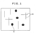
- Fig. 1 is a schematic view of a plane upon observation with the TEM at 500000-fold magnification.
- the plane in Fig. 1 includes Q phases 30 and ⁇ phases 31.
- the Q phases 30 each have a relatively long, black needle-like shape.
- each Q phase 30 refers to the longitudinal dimension of the needle.
- the image in the schematic view is defined as one view field, and the average of the major axes of the Q phases 30 in five view fields is defined as the "major axis (dimension) of Q phase”.
- the measurement region of the major axis of Q phase is not limited, as long as being, for example, a transverse section (cross section in the transverse direction) including the maximum-stress-receiving region as described below.
- the major axis of Q phase may be controlled by chemical composition and conditions for the tempering step including quenching, drying, and over-aging.
- Average grain size in maximum-stress-receiving region 50.0 pm or less in terms of minor axis
- the average grain size affects mechanical properties.
- the Al alloy forging when having an average grain size of 50.0 ⁇ m or less in terms of minor axis in the maximum-stress-receiving region, has higher strength. Consequently, the average grain size in the maximum-stress-receiving region is preferably 50.0 ⁇ m or less in terms of minor axis.
- the average grain size is more preferably 45.0 pm or less, and furthermore preferably 40.0 pm or less, from the viewpoint of offering still higher strength.
- the lower limit is not limited. Theoretically, the smaller the average grain size in terms of minor axis is, the better, but the average grain size is substantially limited to 5.0 ⁇ m or more in terms of lower limit.
- the maximum-stxess-receiving region is the site indicated in Fig. 3 and will be described later.
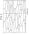
- the average grain size can be calculated by a minor-axis section method. Specifically, the average grain size can be determined by calculation in the following manner, as illustrated in Fig. 2 .
- the surface or cut section of the Al alloy forging is etched with an appropriate etchant, and an image of the etched surface or cut section is taken with an optical microscope at 50-fold magnification.
- a straight line is drawn in a direction perpendicular to the major axes of grains, the number of grains on the straight line is counted, and the straight line length is divided by the grain number to give the average grain size.
- the measurement region of the average grain size is not limited, as long as being, for example, a transverse section including the after-mentioned maximum-stress-receiving region.
- the average grain size may be controlled by chemical composition, forging conditions, and tempering step conditions.
- the area percentage of recrystallized grains in the transverse section including the maximum-stress-receiving region is preferably controlled to be 30.0% or less.
- the Al alloy forging, when having an area percentage of recrystallized grains of 30.0% or less, has higher strength and higher toughness. The lower limit is not specified, but the smaller the area percentage is, the better.
- the term "transverse section" refers to such a cross section as to have a minimum area.
- the area percentage of recrystallized grains in the transverse section including the maximum-stress-receiving region may be controlled by homogenization temperature, forging start temperature (forging initiation temperature) and forging finish temperature (forging end temperature) upon forging, and solution heat treatment conditions.
- Figs. 3 and 4 illustrate a representative shape of the automobile suspension part as an Al alloy forging according to an embodiment of the present invention.
- Fig. 3 is a plan view of the automobile suspension part 1 and illustrates the shape of the entire part and the specific site of an arm portion where the maximum stress occurs.
- Fig. 4 is a cross-sectional view taken along the line A-A of Fig. 3 and is a cross-sectional view in the transverse direction of the specific site of the arm portion receiving the maximum stress.
- the automobile suspension part 1 includes the Al alloy forging which has been forged into this shape.
- the automobile suspension part 1 has an approximately triangular shape as a whole as illustrated in Fig. 3 and includes joint portions 5a, 5b, and 5c, such as ball joints, at the apices of the triangle; and arm portions 2a and 2b that couple the joint portions to each other.
- the arm portions 2a, and 2b include ribs in peripheries (both side edges) in the transverse direction. The ribs extend in the longitudinal direction in each arm portion.
- the arm portion 2a includes ribs 3a and 3b, and the arm portion 2b includes ribs 3a and 3c.
- the arm portions 2a and 2b each include a web at the center part in the transverse direction, where the web extends in the longitudinal direction of the arm portion.
- the arm portion 2a includes a web 4a
- the arm portion 2b includes a web 4b.
- the ribs 3a, 3b, and 3c each have a relatively small width and a relatively large thickness in common in the automobile suspension part.
- the webs 4a and 4b each have a smaller thickness of about 10 mm or less and a relatively larger width in common in the automobile suspension part, as compared with the ribs 3a, 3b, and 3c.
- the arm portions 2a and 2b each have an approximately H-shaped cross section as the cross section in the transverse direction, in common in the automobile suspension part. In the approximately H-shaped cross section, the both vertical wall portions correspond to the ribs 3a, 3b, and 3c, and the central lateral wall portion corresponds to the webs 4a and 4b.
- a general automobile suspension part may be designed in structure of the arm portions 2a and 2b and the ball joint portions 5a, 5b, and 5c so that a specific region receiving the maximum stress during usage (maximum-stress-receiving region) is located in the rib near to the ball joint portion, based on the premise that the automobile suspension part has the entire structure and shape as described above.
- the maximum-stress-receiving region may naturally vary depending on the structure design conditions, but is often located in any of the ribs.
- the specific site where the maximum stress occurs during use is a shaded region that is located in the rib near to the ball joint portion and extends in the longitudinal direction, as indicated with slanted lines in Fig. 3 .
- the specific site in the embodiment illustrated in Fig. 3 is a site that is indicated with slanted lines, is located in one side of the arm portion 2a near to the ball joint portion 5a, and includes part of the rib 3a and part of the web 4a.
- the maximum-stress-receiving region in the area of the arm portion is not uniform in the transverse section and corresponds to a region 6a in the top end of the rib 3a, as circled in Fig. 4 .
- the specific maximum-stress-receiving region in use extends not only to the rib 3a, but also to the rib 3b.
- a region 6b in the top end of the rib 3b also acts as a maximum-stress-receiving region in use, where the region 6b is circled in Fig. 4 .
- the joint portions 5a, 5b, and 5c with other members also naturally receive large stress, but the stress is not the maximum stress.
- the maximum stress in the automobile suspension part occurs in a region of a specific rib near to a ball joint portion, as illustrated in Fig. 3 , where the specific arm portion is determined by the entire shape and dimensional conditions of the arm portion.
- the maximum -stress-receiving region may vary depending typically on the shape and manufacturer's demand characteristics of the automobile suspension part.
- the average grain size may be specified in the maximum-stress-receiving region, and the area percentage of recrystallized grains may be specified in a transverse section including the maximum-stress-receiving region.
- the rib, or the web including the rib becomes susceptible to grain coarsening, where the rib or the web is to have strength at certain level In this case, it is difficult to reduce the weight while maintaining the strength of the arm portion and the strength of the entire automobile suspension part at high levels.
- the area percentage of recrystallized grains in a transverse section including a specific site of the arm portion is specified in the present invention, where the specific site receives the maximum stress.
- the specific site is indicated with slanted lines in Fig. 3 and is a site that is present in one side of the arm portion 2a near to the ball joint portion 5a and includes part of the rib 3a and part of the web 4a.
- the microstructure is preferably controlled as mentioned above not only in the maximum-stress-receiving specific site of the arm portion, but also in the entire arm portions 2a and 2b.
- the area ratio of recrystallized grains is controlled in two sites including the parting line (PL region), out of the transverse section microstructure in the arm portion 2a receiving the maximum load
- the parting line is most susceptible to recrystallization, as described above.
- the "area ratio of recrystallized grains” is also referred to as a "recrystallization area ratio".
- the two sites are a site including the entire microstructure in the transverse section of the rib 3a; and a site including the entire microstructure in the transverse section of the adjacent web 4a.
- the recrystallization area ratio of the arm portion including both the ribs and the web is preferably controlled in the above manner.
- the web 4a is also susceptible to recrystallization, as with the PL region.
- the size (recrystallization area ratio) of grains in the web also significantly affects the strength. Since the web is forged to a working ratio different from that of the rib, the web may highly possibly have a recrystallization area ratio different from that of the rib. Accordingly, the recrystallization area ratio of the arm portion receiving the maximum stress is preferably specified (controlled) both in the web and the rib.
- This configuration restrains recrystallization in the arm portion receiving the maximum stress (in particular, the rib and the web), increases subgrains, allows grains to be refined to about 50.0 ⁇ m or less, and restrains grain boundary failure in the arm portion.
- the automobile suspension part is allowed to have higher strength and higher toughness.
- the specific sites of the rib are specified (measured) as regions receiving the maximum stress in the transverse section, out of the entire microstructure in the transverse section of the rib 3a in Fig. 4 .
- the specifying (measurement) of the specific sites of the rib is performed at two sites, i.e., a site 7 and a site 8 in Fig. 4 .
- the site 7 includes the region 6a in the top end of the rib 3a, where the region 6a is circled in Fig. 4 .
- the site 8 includes the parting line (PL region), where the PL region is most susceptible to recrystallization, as mentioned above.
- microstructures in the measurement sites 7 and 8 are treated as representative microstructures of the entire microstructure in the transverse section of the rib, and the area ratios of recrystallized grains in the two sites are controlled to be 30.0% or less in terms of average area percentage.
- This configuration is preferred to increase subgrains and to allow grains to be refined to an average grain size of about 50.0 ⁇ m or less. This restrains grain boundary failure of the rib and allows the automobile suspension part to have higher strength and higher toughness.
- the specific site in the web is specified (measured) as a site 9 including the parting line (PL region), where the PL region is most susceptible to recrystallization, out of the entire microstructure in the transverse section of the web 4a in Fig. 4 .
- a microstructure in the measurement site 9 is treated as a representative microstructure of the entire microstructure in the transverse section of the web, and the area ratio of recrystallized grains in this site is controlled to be 30.0% or less in terms of average area percentage.
- This configuration is preferred to increase subgrains and to allow grains to be refined to an average grain size of about 50.0 ⁇ m or less. This restrains grain boundary failure of the web and allows the automobile suspension part to have higher strength and higher toughness.
- the area ratio of recrystallized grains can be measured in the following manner. First, each of samples (cross-section microstructures) at measurement sites of the rib and the web are each mechanically polished by 0.05 to 0.1 mm and etched with cupric chloride. Images of the specific sites (measurement sites) are taken typically with a digital camera, subjected to image processing, and the ratio of the recrystallized grain area to the observed view-field area is calculated.
- the recrystallized grains have large sizes, readily reflect light, and appear light-colored. In contrast, other grains including subgrains have small sizes and appear dense-colored.
- the recrystallized grains and the other grains can be distinguished from each other by the differences in size and in color density as mentioned above, and this enables image processing.
- the conditions specified for the microstructure as mentioned above contribute to higher strength and higher toughness particularly of the rib and web of the arm portion, where the rib and web include the maximum-stress-receiving region.
- the microstructural conditions contribute to higher strength and higher toughness of the region receiving the maximum stress in the arm portion.
- the microstructural conditions allow an automobile suspension part to have higher strength, higher toughness, and better corrosion resistance, even when the automobile suspension part includes an arm portion having an approximately H-shaped cross section.
- the H-shaped cross section includes a web and ribs, where the web has a small thickness of about 10 mm or less and a relatively large width and is present in the central part of the arm portion, and the ribs have a smaller width and a larger thickness as compared with the web and are present in peripheries of the arm portion.
- the microstructural conditions allow an automobile suspension part to have higher strength, higher toughness, and better corrosion resistance, even when the suspension part has a shape designed for weight reduction.
- the maximum-stress-receiving region has been illustrated herein while taking the automobile suspension part (Al alloy forging) having the shape illustrated in Figs. 3 and 4 .
- the conditions for the maximum-stress-receiving region will be applied also to automobile suspension parts having other shapes.
- the microstructural conditions specified in the present invention for automobile suspension parts may be applied also to any other cross-section shapes than the H-shaped cross-section shape including ribs and a web.
- the microstructural conditions specified in the present invention may be applied to a microstructure in a maximum-stress-receiving region, out of the microstructure of a transverse (crosswise) section. Specifically, control of the area percentage of recrystallized grains observed in the microstructure in a transverse section including a maximum-stress-receiving region to 30.0% or less allows the maximum-stress-receiving region to have higher strength and higher toughness in the cross section.
- the aluminium alloy forging is used to produce an automobile suspension member.
- Examples of the automobile suspension members include, but are not limited to, upper arms and lower arms.
- a non-limiting example in shape of final products is an automobile suspension part having the shape as illustrated in Figs. 3 and 4 .
- the automobile suspension part includes an arm portion that includes ribs and a web and has an approximately H-shaped cross section.
- the ribs are located in peripheries and have a relatively small width and a large thickness.
- the web are located in a central portion and has a small thickness of about 10 mm or less and a relatively large width.
- the aluminium alloy suspension member according to the present invention may have undergone a surface treatment.
- the Al alloy forging, when having undergone the surface treatment, has still better corrosion resistance.
- the surface treatment will be described in the after-mentioned surface treatment step.
- the aluminium alloy forging preferably has a hydrogen gas concentration controlled within the range as follows.
- Hydrogen (H 2 ) often causes forging defects such as bubbles, thereby acts as fracture origin, and causes the Al alloy forging to readily have lower toughness and lower fatigue properties, particularly when the Al alloy forging is processed at a low working ratio.
- Hydrogen has significant effects particularly on high-strength structural components of transportation equipment and other parts or members. To eliminate or minimize this, the hydrogen content is preferably minimized and controlled to 0.25 ml or less per 100 g of Al.
- the production method according to the present invention is a method for producing the above-mentioned forged aluminum alloy and includes the steps of melting, casting, homogenization, forging, and tempering.
- the production method may further include a surface treatment step and/or a degassing step, as needed.
- the melting step is the step of melting an Al alloy having the chemical composition into a molten metal
- the casting step is the step of casting the molten metal to give an ingot, where the molten metal is prepared by melting (in the melting step) so as to have the chemical composition.
- the casting is performed by a common melting casting technique selected as appropriate.
- the melting-casting technique is exemplified by, but is not limited to, continuous casting-directed rolling, semicontinuous casting (direct chill casting (DC casting)), and hot top casting (hot top direct chill casting).
- the ingot is not limited in shape and may be in any form such as round bars and other ingots, and slabs.
- the cooling of the molten metal to give the ingot is preferably performed at a cooling rate of 10°C/sec or more.
- the cooling when performed at a cooling rate in this range, allows Al-Fe-Si-(Mn, Cr, Zr) crystallized grains present at grain boundaries to have a smaller average grain size and to be present at larger average spacing between them. This allows the Al alloy forging to have strength, toughness, and corrosion resistance at still higher levels.
- the "cooling rate" of the molten metal in this step is defined as an average cooling rate from the liquidus temperature to the solidus temperature.
- the homogenization step is the step of subjecting the ingot to homogenization.
- the homogenization of the ingot in the homogenization step is preferably performed at a holding temperature of 400°C to 560°C.
- the homogenization when performed at a holding temperature of 560°C or lower, causes the (Fe, Mn, Cr, Zr) 3 SiAl 12 dispersed particles themselves to resist coarsening and to less increase in number. This allows a relatively large number of fine dispersed particles dispersed in grains, readily gives an unrecrystallized structure, and consequently allows the Al alloy forging to have strength, toughness, and corrosion resistance at higher levels.
- the homogenization when performed at a holding temperature of 400°C or higher, often allows the (Fe, Mn, Cr, Zr) 3 SiAl 12 dispersed particles to maintain their sizes at such a level as to restrain the recrystallization and to be present in a larger number, where the dispersed particles themselves contribute to restrained recrystallization.
- the homogenization allows the Al-Fe-Si-(Mn, Cr, Zr) crystallized grains to be dissolved as solutes sufficiently and allows Mg 2 Si and Al-Fe-Si-(Mn, Cr, Zr) crystallized grains to readily have a smaller average grain size and to readily have a larger average spacing between them, where the crystallized grains are present at grain boundaries in the microstructure of the Al alloy forging after the tempering step mentioned below.
- the holding temperature is preferably controlled within the range of 400°C to 560°C.
- the holding time at the holding temperature is preferably 3 hours or longer.
- the homogenization may employ a furnace as appropriately selected typically from air furnaces, induction heating furnaces, and salt-bath furnaces.
- the "rate of temperature rise" of the ingot in this process refers to an average rate of temperature rise from room temperature up to the holding temperature.
- the forging step is the step of heating the ingot after homogenization as a forging material and subjecting the heated ingot to hot forging.
- the forging material in the form typically of an ingot or extruded bar is hot-forged typically via mechanical press forming or oil hydraulic press forming.
- the hot forging of the forging material is preferably started at a temperature of 500°C or higher.
- the hot forging when performed at a start temperature of 500°C or higher, allows subgrain phases to occupy a larger proportion of the as-forged structure, thereby increases grain boundaries in the as-forged structure, and accelerates precipitation of Mg 2 Si. This allows the Al alloy forging to have strength, toughness, and corrosion resistance at higher levels.
- the start temperature is preferably controlled to be 500°C or higher.
- the start temperature is more preferably 520°C or higher from the viewpoint of restrainment of recrystallization.
- the hot forging of the forging material is preferably finished at a temperature of 400°C or higher.
- Such high-temperature plastic working in the present invention accelerates dynamic recovery and lowers the dislocation density after working. This restrains grain coarsening caused by recrystallization, allows the Al alloy forging to have an unrecrystallized structure as the microstructure, and allows the Al alloy forging to have strength, toughness, and corrosion resistance at higher levels.
- the forging when performed at an end temperature of 400°C or higher, accelerates dynamic recovery and allows the Al alloy forging to have strength, toughness, and corrosion resistance at higher levels.
- the forging finish temperature is preferably controlled to be 400°C or higher, and is more preferably 420°C or higher.
- the forging material may be one prepared by subjecting the homogenized ingot to working such as extrusion and/or rolling, so as to eliminate or minimize an as-cast structure remained in the Al alloy forging and to allow the Al alloy forging to have strength and toughness at still higher levels.
- the control of the forging finish temperature in the hot forging of the forging material may require a technique such as reheating before hot forging or use of a tool with which the work can be held at high temperatures.
- the hot forging is preferably performed via mechanical forging, and the number of forging procedures is preferably 3 or less.
- the Al alloy forging may have any shape not limited, such as a near net shape near to the final product shape.
- a non-limiting example of the final product shape is the shape of the automobile suspension part as illustrated in Fig. 3 .
- the Al alloy forging after the forging may be subjected to trimming so as to remove unnecessary portions.
- the tempering step is performed after the forging step and is the step of performing solution heat treatment, quenching, drying, and over-aging.
- the tempering step is performed so as to offer strength, toughness, and corrosion resistance necessary as an Al alloy forging.
- the tempering step include T6, T7, and T8 tempers.
- the T6 temper sequentially includes solution heat treatment, quenching, and artificial aging to give maximum strength.
- the T7 temper sequentially includes solution heat treatment, quenching, and over-aging under conditions exceeding the conditions of artificial aging to give maximum strength.
- the T8 temper sequentially includes solution heat treatment, quenching, cold working, and artificial aging to give maximum strength.
- the tempering step in the present invention is performed after the forging step and includes solution heat treatment; quenching at 20°C to 70°C for 30 minutes or shorter; drying for one hour or shorter; and over-aging at 180°C to 220°C for 2 to 24 hours performed in this sequence.
- the solution heat treatment is preferably performed at a holding temperature of from 500°C to 580°C.
- the solution heat treatment when performed at a holding temperature of 500°C or higher, accelerates solutionization, increases solute Mg 2 Si, and allows the Al alloy forging to have higher 0.2% yield strength.
- the solution heat treatment when performed at a holding temperature of 580°C or lower, less causes local melting and grain coarsening, and allows the Al alloy forging to have higher 0.2% yield strength.
- the holding temperature is preferably controlled to be from 500°C to 580°C.
- the solution heat treatment is preferably performed for a holding time of 20 minutes to 20 hours at a rate of temperature rise of 100°C/ hour or more, so as to ensure 0.2% yield strength.
- the "rate of temperature rise" of the Al alloy forging herein refers to the average rate of temperature rise from the solution heat treatment start temperature up to the holding temperature.
- the quenching is performed at a temperature of 20°C to 70°C.
- the quenching if performed at a temperature lower than 20°C, excessively rapidly cools the work to cause a larger difference in temperature between the inside and the outside of the forging to thereby cause strain.
- the quenching if performed at a temperature higher than 70°C, cools the work at an excessively low cooling rate and causes coarse precipitates to form during cooling, where the coarse precipitates do not contribute to higher strength. This causes the Al alloy forging to fail to have sufficient 0.2% yield strength.
- the quenching temperature affects the Q phase. For these reasons, the quenching temperature is controlled to be 20°C to 70°C, and is preferably 30°C to 60°C.
- the quenching is performed for a time of 30 minutes or shorter.
- the quenching if performed for a time longer than 30 minutes, may cause precipitation to initiate during quenching and causes the Al alloy forging to fail to have sufficient 0.2% yield strength.
- the quenching time affects the Q phase. For these reasons, the quenching time is controlled to be 30 minutes or shorter.
- the lower limit of the quenching time may vary depending on the size and weight of the Al alloy forging and may be set so as to give a time necessary for advantageous effects of the quenching.
- the quenching may be performed via cooling by immersing the work in water or warm water, or by showering the work with water or warm water.
- the cooling (quenching) is preferably performed at a cooling rate of 40°C/sec or more so as to eliminate or minimize reduction in toughness and fatigue properties.
- the solution heat treatment may employ equipment selected typically from air furnaces, induction heating furnaces, salt-bath furnaces as appropriate.
- the Al alloy forging after quenching is sufficiently dried before aging. However, the drying is performed for a time of one hour or shorter. The drying, if performed for a time longer than one hour, causes formation of precipitates (cluster I) due to natural aging, as mentioned below, where the precipitates (cluster I) do not contribute to higher strength.
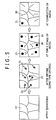
- Fig. 5 is a schematic view of a microstructure when drying after quenching is performed for a long time.
- Fig. 6 is a schematic view of a microstructure when drying after quenching is performed for a short time.
- Fig. 7 is a graph illustrating how the strength of the Al alloy forging varies depending on the aging time in a sample subjected to long-time drying and a sample subjected to short-time drying.
- the cluster I is a cluster of precipitates that do not contribute to higher strength.
- the cluster II is a cluster of precipitates that contribute to higher strength. However, drying performed for a short time does not cause the formation of the cluster II in some cases, as mentioned below.
- the cluster I and the cluster II are formed by aggregation of Si, Mg, and Cu.
- drying after quenching performed for a long time causes formation of a large number of cluster I (21) and a small number of cluster II (22) in grains 10 after drying.
- the cluster I (21) gradually disappears due to reversion.
- the cluster II (22) acts as precipitates, is converted via a Guinier-Preston zone (GP-zone) 25 into a Q phase 30 (or into a ⁇ phase 31 in some cases), where the GP-zone 25 is a precursor of the Q phase 30 and the ⁇ phase 31.
- GP-zone 25 is a precursor of the Q phase 30 and the ⁇ phase 31.
- new GP-zones 25 are also formed.
- the new GP-zones 25 are derived from clusters II (22) newly formed during the aging.
- the GP-zones 25 are converted into the Q phases 30 and/or the 6 phases 31; and the clusters I (21) disappear due to reversion.
- the strength in the sample subjected to long-time drying (sample L) reaches its peak slower as compared with the sample subjected to short-time drying (sample S).
- the sample subjected to short-time drying includes a smaller amount of the cluster I(21) formed during the drying and includes a larger amount of clusters II (22) newly formed during the aging, as compared with the sample subjected to long-time drying. Accordingly, the sample subjected to short-time drying includes a larger amount of GP-zones 25 formed in the early stages of the aging, as compared with the sample subjected to long-time drying.
- the GP-zones 25 are converted into the Q phases 30 and/or the B phases 31; and the cluster I(21) disappears due to reversion.
- the strength reaches its peak earlier in the sample subjected to short-time drying (sample S) as compared with the sample subjected to long-time drying (sample L), as illustrated in Fig. 7 .
- sample Al alloy forging (sample S) subjected to short-time drying has higher strength as compared with the sample Al alloy forging (sample L) subjected to long-time drying.
- drying when performed for a time of one hour or shorter, allows the A1 alloy forging to have higher strength.
- the short-time drying also allows the strength to reach its peak earlier, and this allows the aging to be performed for a shorter time and allows the Al alloy forging to offer better productivity.
- the drying time is controlled to be one hour or shorter, and is preferably 0.5 hour or shorter.
- the drying may be performed according to a known common procedure, as long as the surface can be sufficiently dried.
- the surface of the Al alloy forging has only to be dried such that no moisture remains. For example, the surface may be dried typically via forced-drying for 10 seconds using a fan.
- the corrosion resistance and stress corrosion cracking resistance of the Al alloy forging have a significant relationship with grain boundary precipitates.
- the age hardening if performed as subaging or peak aging, causes grain boundary precipitates to precipitate as fine precipitates in a high density, and the grain boundary precipitates act as origins of corrosion and often cause continuous corrosion.
- the age hardening when performed as over-aging, causes the grain boundary precipitates to coarsen.
- Such age hardening performed as over-aging allows the grain boundary precipitates to be present at wider spacing between each other, and this retards the proceeding of corrosion after corrosion proceeds to a certain extent.
- the over-aging allows the Al alloy forging to resist corrosion.
- the temperature and time of the averaging significantly affect the Q phase after over-aging. This requires selection of such conditions as to give a required 0.2% yield strength and to give other required properties such as toughness, elongation, and corrosion resistance, where the selection is done in consideration of the production history prior to this process.
- the over-aging conditions may be selected within the range of 180°C to 220°C for 2 to 24 hours for strength, toughness, and corrosion resistance at higher levels, where the conditions may vary also depending on the alloy element contents and the production history (conditions) prior to the over-aging, and actual conditions should be checked on each production process and production equipment.
- the over-aging if performed at a temperature lower than 180°C and/or for a time shorter than 2 hours, is performed insufficiently and causes the Al alloy forging to have strength and corrosion resistance at lower levels. In contrast, the over-aging, if performed at a temperature higher than 220°C and/or for a time longer than 24 hours, causes the Al alloy forging to have strength, elongation, and toughness at lower levels. To eliminate or minimize these, the overaging is performed at a temperature of 180°C to 220°C for 2 to 24 hours. The over-aging is preferably performed at a temperature of 180°C to 200°C for a time of 4 to 12 hours.
- the over-aging may be performed using equipment selected typically from air furnaces, induction heating furnaces, and oil baths as appropriate.
- the surface treatment step is the step of performing a surface treatment on the Al alloy forging after the tempering step.
- Exemplary techniques of the surface treatment include surface treatments typically via cathodic electrodeposition, or surface coating (e.g., GEOMET® treatment and powder coating).
- the cathodic electrodeposition and surface coating may be performed according to common, known procedures without limitation.
- the surface treatment allows the Al alloy forging to have still better corrosion resistance.
- the surface treatment may also be shot blasting.
- the shot blasting may be performed according to a common, known procedure without limitation.
- the shot blasting applies compressive residual stress to the Al alloy forging surface and reduces tensile stress, where the tensile stress causes stress corrosion cracking.
- Al alloy forging having a relatively high Cu content within the chemical composition range specified in the present invention did not undergo stress corrosion cracking in a stress corrosion cracking test for 90 days.
- this Al alloy forging when subjected to a stress corrosion cracking test for a longer period of 180 days to obtain higher reliability, suffered from stress corrosion cracking.
- the Al alloy forging having the chemical composition when subjected to shot blasting using glass beads at 0.3 MPa for 90 seconds, did not undergo stress corrosion cracking even after 180-days testing.
- the production method according to the present invention preferably further includes a degassing step between the melting step and the casting step.
- the degassing step is the step of removing hydrogen gas from the molten metal melted in the melting step so as to control the hydrogen gas concentration to 0.25 ml or less per 100 g of the aluminum alloy.
- the degassing step is the step of performing a degassing treatment.
- the hydrogen gas removal may be performed in a holding furnace by fluxing, chlorine refining, or, in-line refining of the molten metal, where the holding furnace is used for control of the molten metal chemical composition and for removal of inclusions.
- the hydrogen gas is preferably removed by blowing an inert gas such as argon gas into the molten metal using spinning nozzle inert flotation (SNIF) or a porous plug (see Japanese Unexamined Patent Application Publication No. 2002-146447 ) in an apparatus for removing the hydrogen gas.
- SNIF spinning nozzle inert flotation
- porous plug see Japanese Unexamined Patent Application Publication No. 2002-146447
- the determination of the hydrogen gas concentration is performed by measuring the hydrogen gas concentration of the ingot produced in the casting step, or of the forging produced in the forging step.
- the hydrogen gas concentration of the ingot can be determined typically by cutting a sample out of the ingot prior to the homogenization, ultrasonically cleaning the sample with an alcohol and acetone, and measuring the hydrogen gas concentration typically by the inert gas fusion thermal conductivity detection (LIS A06-1993).
- the hydrogen gas concentration of the forging can be determined typically by cutting a sample out of the forging, immersing the sample in a NaOH solution, removing an oxide coating from the surface of the sample with nitric acid, ultrasonically cleaning the sample with an alcohol and acetone, and measuring the hydrogen gas concentration typically via the volumetric method using hot vacuum extraction (LIS A06-1993).
- the production method according to the present invention may further include a preforming step typically using a forging roll, prior to the forging step.
- Al alloys having chemical compositions given in Table 1 were cast via hot-top casting at a cooling rate of 20°C/sec into ingots in the form of round bars having a diameter of 68 mm and a length of 580 mm.
- the ingots were subjected to homogenization at a rate of temperature rise of 5°C/min and a holding temperature of 550°C for a holding time of 4 hours.
- hot forging was performed three times so that the total forging working ratio reached 75%.
- the hot forging was performed via mechanical forging using upper and lower dies (tools) at a forging start temperature of 520°C and a forging finish temperature of 420°C.
- the hot forging yielded Al alloy forgings having the shape of an automobile suspension member as illustrated in Figs. 3 and 4 .
- the forgings each had a thickness in the thinnest portion of 6 mm.
- the Al alloy forgings were subjected to solution heat treatment at 550°C for 4 hours in an air furnace, followed by water cooling (water quenching) at 40°C for 15 minutes, and drying for 10 minutes to dryness. Subsequently, the Al alloy forgings were subjected to overaging at 190°C for 5 hours in an air furnace.
- test specimens were sampled from a maximum-stress-receiving region of each Al alloy forging and subjected to measurements on average grain size in terms of minor axis, area percentage, and major axis of Q phase as microstructural forms, as presented in Table 2.
- the test specimens were also subjected to determinations of Al alloy forging properties including tensile properties such as tensile strength, 0.2% yield strength, and elongation, and Charpy impact value (mechanical property).
- the tensile properties are indices of strength, and the Charpy impact value is an index of toughness.
- Each of data in Table 2 is an average of values measured on the three test specimens sampled from each Al alloy forging.
- the test specimens were sampled from the site 7 in Fig. 4 and had a parallel portion diameter of 7 mm, a gauge length of 25 mm, and a total length of 90 mm, which size is a subsize of the No. 4 test specimen prescribed in JIS Z 2241:2011.
- the average grain size (in micrometer) was measured in the site 7 illustrated in Fig. 4 .
- the average grain size (in micrometer) was determined by etching the cut section of each Al alloy forging with Barker's solution, taking an image of the etched cut section at 50-fold magnification via polariscopy using an optical microscope, drawing a straight line in a direction perpendicular to the major axes of grains, counting the number of grains on the straight line, and dividing the length of the straight line by the measured number of grains (see Fig. 2 ).
- Each measurement site was defined herein typically as a region of the Al alloy forging excluding a region of 2 mm deep from the surface, so as to exclude the recrystallized layer in the surface of the Al alloy forging.
- the area ratio of recrystallized grains was measured in the following manner.
- the measurement was performed at two sites, ie., the sites 7 and 8 illustrated in Fig. 4 .
- the measurement was performed at the site 9 illustrated in Fig. 4 .
- the samples from the (cross-section microstructure) observation sites in the rib and the web were mechanically polished by 0.05 to 0.1 mm and etched with cupric chloride. Images of the specified sites were taken with a digital camera, subjected to image processing, and the ratio of the area of recrystallized grains to the area of observation view field was calculated and defined as the area ratio of recrystallized grains.
- the major axis of Q phase was measured at the site 7 illustrated in Fig. 4 .
- the major axis of Q phase was measured in the following manner.
- a thin-film sample (thickness: 700 to 1200 nm) for transmission electron microscope (TEM) observation was prepared by electropolishing using two solutions, i.e., a 1:9 mixture of perchloric acid and ethanol, and a 1:3 mixture of nitric acid and methanol.
- the microstructure of the thin-film sample was observed in five view fields at an acceleration voltage of the transmission electron microscope of 120 kV while applying beams at ⁇ 001> to the matrix and performing the observation in the (100) plane with respect to the matrix.
- the observation was performed at 500000-fold magnification.
- the major axes of Q phase were measured based on the observed microstructures, and the average of major axes of Q phases in all the five view fields was calculated and defined as the major axis of Q phase.
- the tensile strength, 0.2% yield strength, and elongation were measured under conditions in conformance with the conditions prescribed in JIS Z 2241:2011.
- the Charpy impact value was measured under conditions in conformance with the conditions prescribed in JIS Z 2242:2005. Criteria for good properties are 380 MPa or more for the tensile strength; 360 MPa or more for the 0.2% yield strength; 10% or more for the elongation; and 10 J/cm 2 or more for the Charpy impact value.
- a C-ring shaped specimen was sampled from each Al alloy forging and subjected to a stress corrosion cracking test.
- the stress corrosion cracking test was performed using the C-ring shaped specimen under conditions in conformance with the conditions of the alternate immersion test prescribed in ASTM G47 (2011).
- the C-ring shaped specimen was immersed in a sodium chloride solution for 10 minutes, and retrieved from the sodium chloride solution and air-dried for 50 minutes; and this procedure (immersion and drying) was repeated for 90 days, while applying stress of 75% of the yield strength in the LT direction (long transverse direction) to the specimen. The specimen was then observed to determine whether stress corrosion cracking occurred.
- a sample suffering from stress corrosion cracking was evaluated as having poor stress corrosion cracking resistance ( ⁇ ); a sample suffering from not stress corrosion cracking, but grain-boundary corrosion was evaluated as having somewhat poor stress corrosion cracking resistance ( ⁇ ), where the grain-boundary corrosion may highly possibly lead to stress corrosion cracking; a sample suffering from neither stress corrosion cracking nor grain-boundary corrosion was evaluated as having good stress corrosion cracking resistance ( ⁇ ); and a sample not suffering from corrosion at all in the aluminum alloy portion was evaluated as having very good stress corrosion cracking resistance ( ⁇ ).
- the results are presented in Table 2.
- Al alloy forgings (Sample Nos. 1 to 18; Examples) meeting the conditions specified within the scope of the present invention had a tensile strength, a 0.2% yield strength, a Charpy impact value, and stress corrosion cracking resistance at excellent levels.
- Al alloy forgings (Sample Nos. 19 to 35; Comparative Examples) not meeting the conditions specified within the scope of the present invention had disadvantages as follows.
- Sample No. 19 had a Mg content less than the lower limit and a major axis of Q phase less than the lower limit and was inferior in 0.2% yield strength, elongation, Charpy impact value, and stress corrosion cracking resistance.
- Sample No. 20 had a Mg content greater than the upper limit and was inferior in elongation, Charpy impact value, and stress corrosion cracking resistance.
- Sample No. 21 had a Si content less than the lower limit and a major axis of Q phase less than the lower limit and was inferior in all the evaluated properties.
- Sample No. 22 had a Si content greater than the upper limit and was inferior in elongation, Charpy impact value, and stress corrosion cracking resistance.
- Sample No. 23 had a Cu content less than the lower limit, was approximately devoid of Q phases, and was inferior in tensile strength and 0.2% yield strength.
- Sample No. 24 had a Cu content greater than the upper limit and a major axis of Q phase greater than the upper limit and was inferior in elongation, Charpy impact value, and stress corrosion cracking resistance.
- Sample No. 25 had Mg, Si, and Cu contents each greater than the upper limit, had a major axis of Q phase greater than the upper limit, and was inferior in elongation, Charpy impact value, and stress corrosion cracking resistance.
- Sample No. 26 did not contain Mn, Cr, and Zr and was inferior in tensile strength, 0.2% yield strength, elongation, and Charpy impact value.
- Sample No. 27 had a Mn content greater than the upper limit and was inferior in tensile strength, 0.2% yield strength, and Charpy impact value.
- Sample No. 28 had a Cr content greater than the upper limit and was inferior in tensile strength, 0.2% yield strength, Charpy impact value, and stress corrosion cracking resistance.
- Sample No. 29 had a Zr content greater than the upper limit and was inferior in tensile strength, 0.2% yield strength, Charpy impact value, and stress corrosion cracking resistance.
- Sample No. 30 had Mn, Cr, and Zr contents each greater than the upper limit and was inferior in tensile strength, 0.2% yield strength, elongation, and Charpy impact value.
- Sample No. 31 had an Fe content greater than the upper limit and was inferior in elongation, Charpy impact value, and stress corrosion cracking resistance.
- Sample No. 32 had an Fe content less than the lower limit, suffered from cracking upon casting, and could not be forged.
- Sample No. 33 had a Ti content greater than the upper limit and was inferior in Charpy impact value.
- Sample No. 34 had Mn, Cr, and Zr contents each less than the lower limit and was inferior in tensile strength and 0.2% yield strength.
- Sample No. 35 did not contain Ti, thereby had a coarse as-cast structure, and suffered from cracking upon forging.
- Al alloy forgings were prepared under conditions given in Table 3.
- the Al alloy forgings each had the shape of an automobile suspension member illustrated in Figs. 3 and 4 .
- the forgings had a thickness in the thinnest portion of 6 mm.
- homogenization was performed at a holding temperature of from 550°C to 570°C for a holding time of 4 hours; and forging was performed at a forging start temperature of from 500°C to 520°C and a forging finish temperature of from 380°C to 420°C.
- Solution heat treatment was performed at a temperature of from 550°C to 580°C.
- Other conditions in the tempering step are as given in Table 3.
- Other production conditions are as with First Experimental Example.
- test specimens were sampled from a maximum-stress-receiving region in each Al alloy forging and subjected to measurements of average grain size in terms of minor axis, area percentage, and major axis of Q phase as microstructure form, as presented in Table 3.
- the test specimens were also subjected to determination of properties of the Al alloy forging, including tensile properties such as tensile strength, 0.2% yield strength, and elongation, and Charpy impact value (mechanical property), where the tensile properties are indices of strength, and the Charpy impact value is an index of toughness.
- Each of data in Table 3 is an average of values determined on the three test specimens sampled from eachAl alloy forging.
- the measurement of the microstructure form and the evaluation of the properties of the Al alloy forging were performed by methods as in First Experimental Example. The results are presented in Table 3.
- Al alloy forgings (Sample Nos. 36 to 40; Examples) meeting the conditions specified within the scope of the present invention were excellent in tensile strength, 0.2% yield strength, Charpy impact value, and stress corrosion cracking resistance.
- Al alloy forgings (Sample Nos. 41 to 47; Comparative Examples) not meeting the conditions specified within the scope of the present invention have disadvantages as follows.
- Sample No. 41 underwent quenching in the tempering step performed at a quenching temperature lower than the lower limit, had a major axis of Q phase greater than the upper limit, and was inferior in elongation and stress corrosion cracking resistance.
- Sample No. 42 underwent quenching in the tempering step performed at a quenching temperature higher than the upper limit for a quenching time longer than the upper limit, had a major axis of Q phase less than the lower limit, and was inferior in tensile strength and 0.2% yield strength.
- Sample No. 43 underwent drying in the tempering step performed for a drying time longer than the upper limit, had a major axis of Q phase less than the lower limit, and was inferior in tensile strength, 0.2% yield strength, and elongation.
- Sample No. 44 underwent over-aging in the tempering step performed at an over-aging temperature higher than the upper limit, had a major axis of Q phase greater than the upper limit, and was inferior in tensile strength, 0.2% yield strength, elongation, and Charpy impact value.
- Sample No. 45 underwent over-aging in the tempering step performed at an over-aging temperature lower than the lower limit, had a major axis of Q phase less than the lower limit, and was inferior in tensile strength, 0.2% yield strength, and stress corrosion cracking resistance.
- Sample No. 47 underwent over-aging in the tempering step performed for an over-aging time longer than the upper limit, had a major axis of Q phase greater than the upper limit, and was inferior in tensile strength, 0.2% yield strength, elongation, and Charpy impact value.
- Sample No. 47 underwent over-aging in the tempering step performed for an over-aging time shorter than the lower limit, had a major axis of Q phase less than the lower limit, and was inferior in tensile strength, 0.2% yield strength, and stress corrosion cracking resistance.
- Al alloy forgings were subjected to surface treatments under conditions given in Table 4 and subjected to evaluation of stress corrosion cracking resistance. The evaluation was performed by the method as in First Experimental Example.
Description
- The present invention relates to forged aluminum alloys (forged aluminum alloy materials) and methods for producing the forged aluminum alloys, where the forged aluminium alloys are advantageously used as or for automobile suspension members.
- Aluminum alloys such as 6xxx-series (Al-Mg-Si) alloys defined in Japanese Industrial Standards (JIS) or Aluminum Association (AA) Standards have been used in structural components of transportation equipment such as vehicles, ships, air craft, motor-bicycles, and automobiles. The 6xxx-series aluminum alloys have relatively excellent corrosion resistance and can be recycled satisfactorily, because scrap of these aluminum alloys can be reused (recycled) as raw materials to be molten to give 6xxx-series aluminum alloys.
- Such aluminum alloys are often used in the form of aluminum alloy castings and forged aluminum alloys in the structural components of the transportation equipment, from the viewpoints of reduction in production cost, and of processability of materials into parts having complicated shapes. Among them, forged aluminum alloys are mainly used in strength members that require mechanical properties such as higher strength and higher toughness. The strength members are exemplified by automobile suspension members such as upper arms and lower arms. The forged aluminum alloys are produced by homogenizing aluminum alloy castings, subjecting the homogenized castings to hot forging typically via mechanical press forming or oil hydraulic press forming, and performing tempering (heat treatments) such as solution heat treatment, quenching, and artificial aging. The artificial aging is hereinafter also simply referred to as "aging". The forging materials may also be selected from extrusions prepared by homogenizing the castings and extruding the homogenized castings.
- The strength members of the transportation equipment require still further reduction in weight (reduction in thickness) with increasing requirements for lower fuel consumption and lower carbon dioxide (CO2) emission. However, forgings of 6061, 6151, and other 6xxx-series aluminum alloys have been conventionally used in these applications, but inevitably offer insufficient strength (0.2% yield strength) and/or insufficient toughness.
- As possible solutions to these problems, various forged aluminum alloys have been developed. For example, Patent Literature (PTL) 1 discloses an automobile suspension part including a forged aluminum alloy. The forged aluminum alloy contains, in mass percent, Mg in a content of 0.5% to 1.25%, Si in a oontent of 0.4% to 1.4%, Cu in a content of 0.01% to 0.7%, Fe in a content of 0.05% to 0.4%, Mn in a content of 0.001% to 1.0%, Cr in a content of 0.01% to 0.35%, and Ti in a content of 0.005% to 0.1%, where Zr content is controlled to less than 0.15%, with the remainder consisting of Al and inevitable impurities. In the microstructure of a transverse section at a maximum-stress-receiving region, crystallized grains are present in a density of 1.5% or less in terms of average area percentage, where the crystallized grains are observed in the microstructure of a cross-sectional region receiving the maximum stress. Grain boundary precipitates are present at an average spacing between the precipitates of 0.7 pm or more, where the grain boundary precipitates are observed in a microstructure in a cross-sectional region including a parting line formed upon forging.
- The technique disclosed in
PTL 1 is intended to allow automobile suspension parts to have strength, toughness, and corrosion resistance all at higher levels, even when the parts have shapes designed for weight reduction. With the technique, the forged aluminum alloy is allowed to have an unrecrystallized structure by controlling the chemical composition (amounts of transition elements to be added) and production conditions . (mainly forging temperature and homogenization conditions). - In particular, various properties and microstructure (phases) in the maximum-stress-receiving region are specified, because thickness reduction for the purpose of weight reduction often causes recrystallization.
- PTL 2 discloses a forged aluminum alloy for high-strength members. The forged aluminum alloy contains Mg in a content of 0.6% to 1.8%, Si in a content of 0.8% to 1.8%, Cu in a content of 0.2% to 1.0%, and at least one element selected from the group consisting of Mn in a content of 0.1% to 0.6%, Cr in a oontent of 0.1% to 0.2%, and Zr in a content of 0.1% to 0.2%, with the remainder consisting of Al and inevitable impurities, where the mass ratio of Si to Mg is 1 or more. The forged aluminum alloy has a thickness of 30 mm or less in the thinnest portion. After artificial aging, the forged aluminum alloy has an electric conductivity of 41.0 to 42.5 percent IACS and has a 0.2% yield strength of 350 MPa or more, where the electric conductivity is measured at the surface of the forged aluminum alloy.
- The technique disclosed in PTL 2 specifies that the electric conductivity of the forged aluminum alloy surface after aging is from 41.0 to 42.5 percent IACS, so as to allow the forged aluminum alloy to surely have a strength (0.2% yield strength) of 350 MPa or more and to stably have the strength.
-
- PTL 1: Japanese Patent No.
5110938 - PTL 2: Japanese Patent No.
3766357 EP 2 003 219 A2 discloses an aluminium alloy forged member used for automotive underbody parts such as suspension components. The disclosed 6XXX series alloy and its method of manufacture has higher strength, toughness and higher corrosion resistance even when the overall weight of the component is reduced. - As described above, attempts have been made on conventional forged aluminum alloys to have strength and toughness at higher levels. Increasing demands have been made on such materials to have higher strength so as to reduce weights of suspension parts from the viewpoint of providing better fuel efficiency of automobiles. However, the materials, if designed to have still higher strength, may highly possibly cause significant reduction in corrosion resistance and toughness. In particular, the materials, when combined with Cu, Si, Mg, and other elements that contribute to precipitation strengthening, may have significantly reduced corrosion resistance.
- Under these circumstances, the present invention has an object to provide a forged aluminium alloy suspension part and a method for its production, where the forged aluminum alloy offers high strength and high toughness and still has excellent corrosion resistance, even when having a smaller thickness.
- After intensive investigations, the inventors of the present invention have made the present invention particularly in consideration of followings. Specifically, a forged aluminum alloy was designed to have higher strength by adding Si, Cu, and Mg in larger amounts, where these elements contribute to age precipitation. However, Si, Cu, and Mg in larger amounts cause the forged aluminum alloy to have lower toughness and lower corrosion resistance To eliminate or minimize this, the amounts of Mn, Cr, and Zr are controlled, and over-aging is performed under predetermined conditions. In addition, the forged aluminum alloy is allowed to have still higher strength by performing drying in a shorter time as compared with conventional techniques, where the drying is performed after quenching.
- Specifically, to achieve the object, the present invention provides, according to a first embodiment, a forged aluminium alloy suspension part. The forged aluminum alloy includes Mg in a content of 0.70 to 1.50 mass percent, Si in a content of 0.80 to 1.30 mass percent, Cu in a content of 0.30 to 0.90 mass percent, Fe in a content of 0.10 to 0.40 mass percent, Ti in a content of 0.005 to 0.15 mass percent, and at least one element selected from the group consisting ofMn in a content of 0.10 to 0.60 mass percent, Cr in a content of 0.10 to 0.45 mass percent, and Zr in a content of 0.05 to 0.30 mass percent, with the remainder consisting of Al and inevitable impurities. In a maximum-stress-receiving region, a Q phase has a major axis of 50 to 500 nm.
- The forged aluminum alloy having the configuration has strength, toughness, and corrosion resistance at higher levels, because the forged aluminum alloy includes Mg, Si, Cu, Fe, and Ti in the predetermined contents and further includes at least one of Mn, Cr, and Zr each in the predetermined content In addition, the forged aluminum alloy has higher strength (tensile strength and 0.2% yield strength), because the Q phase in the maximum-stress-receiving region has a major axis controlled within the specific range.
- Preferably, the forged aluminum alloy according to the present invention has an average grain size of 50.0 pm or less in terms of minor axis in the maximum-stress-receiving region and has an area percentage of recrystallized grains of 30.0% or less in a transverse section including the maximum-stress-receiving region.
- The forged aluminum alloy having the configuration has still higher strength, because the forged aluminum alloy has an average grain size within the specific range in the maximum-stress-receiving region. The forged aluminum alloy has still higher strength and toughness, because the forged aluminum alloy has an area percentage of recrystallized grains within the specific range in a transverse section including the maximum-stress-receiving region.
- The forged aluminium alloy suspension part according to the invention preferably has undergone a surface treatment.
- The forged aluminum alloy, when having undergone the surface treatment, has still better corrosion resistance.
- The forged aluminium alloy suspension part according to the present invention preferably has undergone shot blasting.
- The forged aluminum alloy, when having undergone shot blasting, has still better stress corrosion cracking resistance.
- The present invention also provides, according to a second embodiment, a method for producing a forged aluminium alloy suspension part. The forged aluminum alloy includes Mg in a content of 0.70 to 1.50 mass percent, Si in a content of 0.80 to 1.30 mass percent, Cu in a content of 0.30 to 0.90 mass percent, Fe in a content of 0.10 to 0.40 mass percent, Ti in a content of 0.005 to 0.15 mass percent, and at least one element selected from the group consisting ofMn in a content of 0.10 to 0.60 mass percent, Cr in a content of 0.10 to 0.45 mass percent, and Zr in a content of 0.05 to 0.30 mass percent, with the remainder consisting of Al and inevitable impurities. The method includes the steps of melting, casting, homogenization, forging, and tempering. In the melting step, an aluminum alloy having the chemical composition is melted to give a molten metal. In the casting step, the molten metal is cast to give an ingot In the homogenization step, the ingot is subjected to homogenization. In the forging step, the homogenized ingot is used as a forging material, is heated, and subjected to hot forging. The tempering step is performed after the forging step and includes, in the following sequence, solution heat treatment, quenching at 20°C to 70°C for 30 minutes or shorter, drying for one hour or shorter, and overaging at 180°C to 220°C for 2 to 24 hours.
- According to the procedure (method), the steps are performed under the predetermined conditions to allow the forged aluminum alloy to have strength, toughness, and corrosion resistance at higher levels. In particular, control of the conditions for quenching, drying, and over-aging allows the Q phase in the maximum-stress-receiving region to have a major axis within the predetermined range and allows the forged aluminum alloy to have higher strength. The over-aging performed under the predetermined conditions allows grain boundary precipitates to distribute at larger spacing, and this allows the forged aluminum alloy to have better corrosion resistance and to still offer higher strength and higher toughness.
- The forged aluminium alloy suspension part according to the present invention offers high strength and high toughness and still has excellent corrosion resistance, even when designed to have a smaller thickness. Accordingly, the forged aluminum alloy can be used in wider uses in transportation equipment and has industrially significant value.
- The method according to the present invention for producing a forged aluminum alloy enables production of a forged aluminum alloy that offers high strength and high toughness and still has excellent corrosion resistance, even when the forged aluminum alloy is designed to have a smaller thickness.
-
-
Fig. 1 is a schematic view of a plane of a forged aluminum alloy according to the present invention as observed with a transmission electron microscope (TEM) at 500000-fold magnification; -
Fig. 2 is a schematic view of a surface or cut section of a forged aluminum alloy and illustrates how to measure the average grain size; -
Fig. 3 is a plan view of a forged aluminum alloy according to an embodiment of the present invention; -
Fig. 4 is a cross-sectional view taken along the line A-A ofFig. 3 ; -
Fig. 5 is a schematic view of a microstructure of a sample subjected to long-time drying after quenching; -
Fig. 6 is a schematic view of a microstructure of a sample subjected to short-time drying after quenching; and -
Fig. 7 is a graph illustrating how the strength of a forged aluminum alloy varies depending on the aging time in a sample subjected to long-time drying, and in a sample subjected to short-time drying. - First, the forged aluminum alloy which is used to produce the suspension part according to the invention will be described. The forged aluminum alloy is hereinafter also referred to as an "Al alloy forging" as appropriate.
- The Al alloy forging according to the present invention includes (is made of) an aluminum alloy containing Mg, Si, Cu, Fe, and Ti in predetermined contents and further containing at least one of Mn, Cr, and Zr in a predetermined content, with the remainder consisting of Al and inevitable impurities. The Q phase in a maximum-stress-receiving region is controlled to have a major axis of 50 to 500 nm.
- The Al alloy forging preferably has an average grain size in the maximum-stress-receiving region of 50.0 pm or less in terms of minor axis and an area percentage of recrystallized grains in a transverse section including the maximum-stress-receiving region of 30.0% or less.
- The configurations will be illustrated below.
- The chemical composition of the Al alloy forging according to the present invention will be described. The Al alloy forging according to the present invention has a chemical composition corresponding to an Al-Mg-Si (6xxx-series) alloy. The chemical composition is specified so as to ensure high strength, high toughness, and high durability such as stress corrosion cracking resistance, for use as structural components or parts of transportation equipment such as automobiles and ships. The chemical composition of the Al alloy forging according to the present invention acts as one of significant factors in conditions specified relating typically to grains.
- Accordingly, the chemical composition of the Al alloy forging according to the present invention is specified to include Mg in a content of 0.70 to 1.50 mass percent, Si in a content of 0.80 to 1.30 mass percent, Cu in a content of 0.30 to 0.90 mass percent, Fe in a content of 0.10 to 0.40 mass percent, Ti in a content of 0.005 to 0.15 mass percent, and at least one element selected from the group consisting of Mn in a content of 0.10 to 0.60 mass percent, Cr in a content of 0.10 to 0.45 mass percent, and Zr in a content of 0.05 to 0.30 mass percent, with the remainder consisting ofAl and inevitable impurities.
- Next, critical significance and preferred ranges of contents of the individual elements in the chemical composition of the Al alloy forging according to the present invention will be described.
- Magnesium (Mg) precipitates, together with Si and Cu, as Mg2Si (β° phase) and Q phase as a result of over-aging and is necessary for imparting a high 0.2% yield strength to the Al alloy forging. Mg, if present in a content less than 0.70 mass percent, causes age hardening to be insufficient and causes the Al alloy forging to have a lower 0.2% yield strength. In addition, Mg in an excessively low content may cause the forged aluminum alloy to have a smaller major axis of the Q phase and to have elongation, toughness, and/or corrosion resistance at lower levels. In contrast, Mg, if present in a content greater than 1.50 mass percent, may cause the forged aluminum alloy to have an excessively high 0.2% yield strength and adversely affect the ingot forgeability. In addition, Mg in a content greater than 1.50 mass percent causes Mg2Si crystallized grains, which do not contribute to higher 0.2% yield strength, to increase upon casting. This causes the Al alloy forging to have toughness and corrosion resistance both at lower levels and may cause the Al alloy forging to have lower elongation. To eliminate or minimize these, the Mg content is controlled to be 0.70 to 1.50 mass percent, and is preferably 0.80 to 1.20 mass percent.
- Silicon (Si) also precipitates, together with Mg and Cu, as Mg2Si (β° phase) and Q phase as a result of over-aging and is necessary for imparting a high 0.2% yield strength to the Al alloy forging. Si, if present in a content less than 0.80 mass percent, causes the Al alloy forging to have a smaller size of the Q phase in terms of major axis, causes age hardening to be insufficient, and causes the Al alloy forging to have a lower 0.2% yield strength. This may also cause the Al alloy forging to be insufficient in properties such as tensile strength, elongation, toughness, and corrosion resistance. In contrast, Si, if present in a content greater than 1.30 mass percent, causes coarse grains of Si alone to form and to precipitate upon casting and during quenching after the solution heat treatment. In addition, such Si in an excessively high content causes Mg2Si and Al-Fe-Si-(Mn, Cr, Zr) crystallized grains at grain boundaries to fail to have a smaller average grain size and to fail to be present at larger average spacing between them. This causes the Al alloy forging to have corrosion resistance and toughness at lower levels, as with Mg, and still causes the Al alloy forging to offer inferior workability such as low elongation. To eliminate or minimize these, the Si content is controlled to be 0.80 to 1.30 mass percent, and is preferably 0.90 to 1.10 mass percent.
- Copper (Cu) contributes to higher 0.2% yield strength via solid-solution strengthening and effectively significantly promotes age hardening of the Al alloy forging upon over-aging. Cu, if present in a content less than 0.30 mass percent, fails to offer these effects sufficiently and causes the Al alloy forging to have lower 0.2% yield strength. Such Cu in an insufficient amount may also cause the Q phase to precipitate insufficiently and may cause the Al alloy forging to have lower tensile strength. In contrast, Cu, if present in a content greater than 0.90 mass percent, causes the Q phase to have a larger major axis and causes the microstructure of the Al alloy forging to have significantly higher susceptibility (sensitivity) to stress corrosion cracking and/or grain-boundary corrosion. This causes the Al alloy forging to have lower corrosion resistance. In addition, such excessive Cu may cause the Al alloy forging to have lower elongation and/or lower toughness. To eliminate or minimize these, the Cu content is controlled to be 0.30 to 0.90 mass percent, and is preferably 0.40 to 0.70 mass percent
- Iron (Fe) is added to the Al alloy forging for better productivity and for less recrystallization upon casting. However, Fe forms Al7Cu2Fe, Al12(Fe, Mn)3Cu2, (Fe, Mn)Al6, and/or Al-Fe-Si(Mn, Cr, Zr) crystallized grains. These coarse precipitates act as fracture origins and cause the Al alloy forging to be inferior in properties such as toughness and fatigue properties. In particular, Fe, if present in a content greater than 0.40 mass percent, causes Al-Fe-Si-(Mn, Cr, Zr) crystallized grains at grain boundaries to have a larger average grain size and to be present at a smaller average spacing between the crystallized grains. This causes the Al alloy forging to have toughness and corrosion resistance at lower levels and may cause the Al alloy forging to have lower elongation. In contrast, Fe, if present in a content less than 0.10 mass percent, may cause disadvantages such as cracking upon casting and/or an abnormal microstructure. To eliminate or minimize these, the Fe content is controlled to be 0.10 to 0.40 mass percent, and is preferably 0.20 to 0.30 mass percent.
- Titanium (Ti) is added for refinement of ingot grains and for better workability upon extrusion, rolling, and forging. However, Ti, if present in a content less than 0.005 mass percent, may fail to offer effective grain refinement In contrast, Ti, if present in a content greater than 0.15 mass percent, forms coarse precipitates, causes the Al alloy forging to be inferior in the workability, and may cause the Al alloy forging to have lower toughness. To eliminate or minimize these, the Ti content is controlled to be 0.005 to 0.15 mass percent, and is preferably 0.01 to 0.10 mass percent.
- At least one element selected from the group consisting of Mn: 0.10 to 0.60 mass percent, Cr: 0.10 to 0.45 mass percent, and Zr: 0.05 to 0.30 mass percent
- These elements form dispersed particles (dispersoids) upon homogenization and subsequent hot forging. The dispersed particles are Al-Mn, Al-Cr, and/or Al-Zr intermetallic compounds formed by bonding of elements such as Fe, Mn, Cr, Zr, Si, and Al selectively according to the contents thereof These intermetallic compounds are generically referred to as (Fe, Mn, Cr, Zr)3SiAl12 compounds.
- The dispersed particles effectively eliminate or minimize grain boundary migration after recrystallization. This configuration eliminates or minimizes coarsening of the average grain size of a parting line microstructure in the ST direction (short transverse direction; thickness direction) during the forging step and, in addition, allows fine grains and fine subgrains to be present overall the Al alloy forging according to the present invention. The elements Mn, Cr, and Zr are expected to allow the Al alloy forging to have higher 0.2% yield strength via solid-solution.
- Manganese (Mn) forms dispersed particles of a size of about 1 pm upon homogenization and is effective for restraining of recrystallization. However, this element increases susceptibility to grain-boundary corrosion and is controlled in the content In addition, Mn is readily combined with Fe to form fragile, coarse precipitates. Accordingly, control of the content allows the Al alloy forging to have better toughness.
- Mn, Cr, and Zr, if present in contents respectively of less than 0.10 mass percent, less than 0.10 mass percent, and less than 0.05 mass percent, are not expected to offer the effects and may cause the Al alloy forging to have tensile strength, elongation, and toughness at lower levels. In contrast, Mn, Cr, and Zr, if present in contents respectively of greater than 0.60 mass percent, greater than 0.45 mass percent, and greater than 0.30 mass percent, readily form crystallized grains as coarse Al-Fe-Si-(Mn, Cr, Zr) intermetallic compounds upon melting and casting. These coarse intermetallic compounds act as fracture origins and cause the Al alloy forging to be insufficient in at least one of tensile strength, elongation, 0.2% yield strength, toughness, and corrosion resistance. To eliminate or minimize these, at least one of these elements is to be contained, in contents within the ranges of 0.10 to 0.60 mass percent for Mn, 0.10 to 0.45 mass percent for Cr, and 0.05 to 0.30 mass percent for Zr. The Mn, Cr, and Zr content are preferably respectively 0.30 to 0.50 mass percent, 0.15 to 0.30 mass percent, and 0.05 to 0.15 mass percent.
- The remainder of the chemical composition of the Al alloy forging consists of Al and inevitable impurities. Possible inevitable impurities are exemplified by Ni, Zn, Be, V, and other elements. Each of these elements may be contained at such a level as not to adversely affect the advantages or features of the present invention. Specifically, the contents of elements as the inevitable impurities are preferably 0.05 mass percent or less per each element, and the total content of them is preferably 0.15 mass percent or less.
- Boron (B) is an inevitable impurity, but contributes to refinement of ingot grains and effectively allows the Al alloy forging to have better workability upon extrusion, rolling, and forging, as with Ti. Boron, however, if present in a content greater than 500 ppm, also forms coarse precipitates and causes the Al alloy forging to be insufficient in the workability. Accordingly, the Al alloy forging may contain boron in a content up to 500 ppm. However, boron, if present in a content less than 1 ppm, fails to offer the advantageous effects. Thus, boron may be contained in a content of 1 ppm or more.
- Next, the requirement on the Q phase major axis in the Al alloy forging will be described.
- As used herein the term "Q phase" refers to a Q phase or a Q' phase. The Q phase is a precipitate including Al5Cu2Mg8Si6, is precipitated via aging, and contributes to higher strength. The Q phase is precipitated slower as compared with the B phase and β° phase (Mg2Si). Thus, aging, even when performed as over-aging in the Al alloy forging production method, can restrain reduction in strength. The major axis of the Q phase is controlled to be 50 nm or more in particular for higher strength and is controlled to be 500 nm or less for higher toughness and/or better corrosion resistance. The Q phase, if having a size in terms of major axis out of the range, may cause the Al alloy forging to be insufficient in one or more of strength, elongation, toughness, and corrosion resistance. To eliminate or minimize these, the major axis of the Q phase is controlled to be from 50 to 500 nm. The "site which receives the maximum stress" is also referred to as a "maximum-stress-receiving region", as appropriate. The maximum-stress-receiving region is a site as indicated in
Fig. 3 and will be described later. - The Q phase measurement may be performed by the following method.
- First, a sample is cut out from the maximum-stress-receiving region of the Al alloy forging. Next, the sample is subjected to electropolishing using two different solutions to give a thin-film sample for transmission electron microscope (TEM) observation. The two solutions are a 1:9 mixture of perchloric acid and ethanol, and a 1:3 mixture of nitric acid and methanoL The microstructure of the thin-film sample is observed in five view fields, while electron beams are applied in the <001> direction with respect to the matrix, and the (100) plane is observed, at an acceleration voltage of the transmission electron microscope of 120 kV. The observation is performed at 500000-fold magnification. The major axes of the Q phases are measured based on the observed microstructure, and the average of the major axes in all the Q phases in the five views fields is calculated. Specifically, the average major axis is calculated by summing up the lengths in major axes of the Q phases in the five view fields, and dividing the total length by the number of the Q phases in the five view fields. The average major axis thus determined is controlled to 50 to 500 nm herein.
Fig. 1 is a schematic view of a plane upon observation with the TEM at 500000-fold magnification. The plane inFig. 1 includes Q phases 30 and β phases 31. The Q phases 30 each have a relatively long, black needle-like shape. The 6 phases 31 also have a needle-like shape, but appear as coffee beans, because the β phases are precipitated in conformance with the matrix and thereby distort the matrix The "major axis" of eachQ phase 30 refers to the longitudinal dimension of the needle. For example, the image in the schematic view is defined as one view field, and the average of the major axes of the Q phases 30 in five view fields is defined as the "major axis (dimension) of Q phase". - The measurement region of the major axis of Q phase is not limited, as long as being, for example, a transverse section (cross section in the transverse direction) including the maximum-stress-receiving region as described below.
- The major axis of Q phase may be controlled by chemical composition and conditions for the tempering step including quenching, drying, and over-aging.
- Next, the conditions on the grains in the Al alloy forging will be described.
- The average grain size affects mechanical properties. The Al alloy forging, when having an average grain size of 50.0 µm or less in terms of minor axis in the maximum-stress-receiving region, has higher strength. Consequently, the average grain size in the maximum-stress-receiving region is preferably 50.0 µm or less in terms of minor axis. The average grain size is more preferably 45.0 pm or less, and furthermore preferably 40.0 pm or less, from the viewpoint of offering still higher strength. The lower limit is not limited. Theoretically, the smaller the average grain size in terms of minor axis is, the better, but the average grain size is substantially limited to 5.0 µm or more in terms of lower limit. The maximum-stxess-receiving region is the site indicated in
Fig. 3 and will be described later. - The average grain size can be calculated by a minor-axis section method. Specifically, the average grain size can be determined by calculation in the following manner, as illustrated in
Fig. 2 . The surface or cut section of the Al alloy forging is etched with an appropriate etchant, and an image of the etched surface or cut section is taken with an optical microscope at 50-fold magnification. A straight line is drawn in a direction perpendicular to the major axes of grains, the number of grains on the straight line is counted, and the straight line length is divided by the grain number to give the average grain size. - The measurement region of the average grain size is not limited, as long as being, for example, a transverse section including the after-mentioned maximum-stress-receiving region.
- The average grain size may be controlled by chemical composition, forging conditions, and tempering step conditions.
- In the Al alloy forging, the area percentage of recrystallized grains in the transverse section including the maximum-stress-receiving region is preferably controlled to be 30.0% or less. The Al alloy forging, when having an area percentage of recrystallized grains of 30.0% or less, has higher strength and higher toughness. The lower limit is not specified, but the smaller the area percentage is, the better. The term "transverse section" refers to such a cross section as to have a minimum area.
- The area percentage of recrystallized grains in the transverse section including the maximum-stress-receiving region may be controlled by homogenization temperature, forging start temperature (forging initiation temperature) and forging finish temperature (forging end temperature) upon forging, and solution heat treatment conditions.
- Next, the maximum-stress-receiving region of the Al alloy forging will be described, while taking an automobile suspension part illustrated in
Figs. 3 and 4 as an example. -
Figs. 3 and 4 illustrate a representative shape of the automobile suspension part as an Al alloy forging according to an embodiment of the present invention.Fig. 3 is a plan view of theautomobile suspension part 1 and illustrates the shape of the entire part and the specific site of an arm portion where the maximum stress occurs.Fig. 4 is a cross-sectional view taken along the line A-A ofFig. 3 and is a cross-sectional view in the transverse direction of the specific site of the arm portion receiving the maximum stress. - As illustrated in
Fig. 3 , theautomobile suspension part 1 includes the Al alloy forging which has been forged into this shape. Theautomobile suspension part 1 has an approximately triangular shape as a whole as illustrated inFig. 3 and includesjoint portions arm portions arm portions arm portion 2a includesribs arm portion 2b includesribs arm portions arm portion 2a includes aweb 4a, and thearm portion 2b includes aweb 4b. - The
ribs webs ribs arm portions ribs webs - A general automobile suspension part may be designed in structure of the
arm portions joint portions - In the automobile suspension part illustrated in
Fig. 3 , the specific site where the maximum stress occurs during use (the maximum-stress-receiving region) is a shaded region that is located in the rib near to the ball joint portion and extends in the longitudinal direction, as indicated with slanted lines inFig. 3 . Specifically, the specific site in the embodiment illustrated inFig. 3 is a site that is indicated with slanted lines, is located in one side of thearm portion 2a near to the balljoint portion 5a, and includes part of therib 3a and part of theweb 4a. In addition, the maximum-stress-receiving region in the area of the arm portion is not uniform in the transverse section and corresponds to aregion 6a in the top end of therib 3a, as circled inFig. 4 . Assume that the specific maximum-stress-receiving region in use extends not only to therib 3a, but also to therib 3b. In this case, aregion 6b in the top end of therib 3b also acts as a maximum-stress-receiving region in use, where theregion 6b is circled inFig. 4 . - In the automobile suspension part, other portions such as the
joint portions Fig. 3 , where the specific arm portion is determined by the entire shape and dimensional conditions of the arm portion. The maximum -stress-receiving region, however, may vary depending typically on the shape and manufacturer's demand characteristics of the automobile suspension part. However, wherever area the maximum-stress-receiving region is located, the average grain size may be specified in the maximum-stress-receiving region, and the area percentage of recrystallized grains may be specified in a transverse section including the maximum-stress-receiving region. - Assume that, out of the maximum-stress-receiving region in the arm portion, the rib, or the web including the rib becomes susceptible to grain coarsening, where the rib or the web is to have strength at certain level In this case, it is difficult to reduce the weight while maintaining the strength of the arm portion and the strength of the entire automobile suspension part at high levels.
- Thus, the area percentage of recrystallized grains in a transverse section including a specific site of the arm portion is specified in the present invention, where the specific site receives the maximum stress. The specific site is indicated with slanted lines in
Fig. 3 and is a site that is present in one side of thearm portion 2a near to the balljoint portion 5a and includes part of therib 3a and part of theweb 4a. When producible, the microstructure is preferably controlled as mentioned above not only in the maximum-stress-receiving specific site of the arm portion, but also in theentire arm portions - In a preferred embodiment of the present invention, the area ratio of recrystallized grains is controlled in two sites including the parting line (PL region), out of the transverse section microstructure in the
arm portion 2a receiving the maximum load The parting line is most susceptible to recrystallization, as described above. The "area ratio of recrystallized grains" is also referred to as a "recrystallization area ratio". With reference toFig. 4 , the two sites are a site including the entire microstructure in the transverse section of therib 3a; and a site including the entire microstructure in the transverse section of theadjacent web 4a. The recrystallization area ratio of the arm portion including both the ribs and the web is preferably controlled in the above manner. - The
web 4a is also susceptible to recrystallization, as with the PL region. The size (recrystallization area ratio) of grains in the web also significantly affects the strength. Since the web is forged to a working ratio different from that of the rib, the web may highly possibly have a recrystallization area ratio different from that of the rib. Accordingly, the recrystallization area ratio of the arm portion receiving the maximum stress is preferably specified (controlled) both in the web and the rib. - This configuration restrains recrystallization in the arm portion receiving the maximum stress (in particular, the rib and the web), increases subgrains, allows grains to be refined to about 50.0 µm or less, and restrains grain boundary failure in the arm portion. Thus, the automobile suspension part is allowed to have higher strength and higher toughness.
- The specific sites of the rib are specified (measured) as regions receiving the maximum stress in the transverse section, out of the entire microstructure in the transverse section of the
rib 3a inFig. 4 . Specifically, the specifying (measurement) of the specific sites of the rib is performed at two sites, i.e., asite 7 and asite 8 inFig. 4 . Thesite 7 includes theregion 6a in the top end of therib 3a, where theregion 6a is circled inFig. 4 . Thesite 8 includes the parting line (PL region), where the PL region is most susceptible to recrystallization, as mentioned above. Namely, it is preferred that microstructures in themeasurement sites - The specific site in the web is specified (measured) as a
site 9 including the parting line (PL region), where the PL region is most susceptible to recrystallization, out of the entire microstructure in the transverse section of theweb 4a inFig. 4 . Specifically, it is preferred that a microstructure in themeasurement site 9 is treated as a representative microstructure of the entire microstructure in the transverse section of the web, and the area ratio of recrystallized grains in this site is controlled to be 30.0% or less in terms of average area percentage. This configuration is preferred to increase subgrains and to allow grains to be refined to an average grain size of about 50.0 µm or less. This restrains grain boundary failure of the web and allows the automobile suspension part to have higher strength and higher toughness. - The area ratio of recrystallized grains can be measured in the following manner. First, each of samples (cross-section microstructures) at measurement sites of the rib and the web are each mechanically polished by 0.05 to 0.1 mm and etched with cupric chloride. Images of the specific sites (measurement sites) are taken typically with a digital camera, subjected to image processing, and the ratio of the recrystallized grain area to the observed view-field area is calculated. The recrystallized grains have large sizes, readily reflect light, and appear light-colored. In contrast, other grains including subgrains have small sizes and appear dense-colored. The recrystallized grains and the other grains can be distinguished from each other by the differences in size and in color density as mentioned above, and this enables image processing.
- The conditions specified for the microstructure as mentioned above contribute to higher strength and higher toughness particularly of the rib and web of the arm portion, where the rib and web include the maximum-stress-receiving region. In short, the microstructural conditions contribute to higher strength and higher toughness of the region receiving the maximum stress in the arm portion. Thus, the microstructural conditions allow an automobile suspension part to have higher strength, higher toughness, and better corrosion resistance, even when the automobile suspension part includes an arm portion having an approximately H-shaped cross section. The H-shaped cross section includes a web and ribs, where the web has a small thickness of about 10 mm or less and a relatively large width and is present in the central part of the arm portion, and the ribs have a smaller width and a larger thickness as compared with the web and are present in peripheries of the arm portion. Namely, the microstructural conditions allow an automobile suspension part to have higher strength, higher toughness, and better corrosion resistance, even when the suspension part has a shape designed for weight reduction.
- The maximum-stress-receiving region has been illustrated herein while taking the automobile suspension part (Al alloy forging) having the shape illustrated in
Figs. 3 and 4 . The conditions for the maximum-stress-receiving region, however, will be applied also to automobile suspension parts having other shapes. - The microstructural conditions specified in the present invention for automobile suspension parts may be applied also to any other cross-section shapes than the H-shaped cross-section shape including ribs and a web. For example, the microstructural conditions specified in the present invention may be applied to a microstructure in a maximum-stress-receiving region, out of the microstructure of a transverse (crosswise) section. Specifically, control of the area percentage of recrystallized grains observed in the microstructure in a transverse section including a maximum-stress-receiving region to 30.0% or less allows the maximum-stress-receiving region to have higher strength and higher toughness in the cross section.
- The aluminium alloy forging is used to produce an automobile suspension member.
- Examples of the automobile suspension members include, but are not limited to, upper arms and lower arms. A non-limiting example in shape of final products is an automobile suspension part having the shape as illustrated in
Figs. 3 and 4 . The automobile suspension part includes an arm portion that includes ribs and a web and has an approximately H-shaped cross section. The ribs are located in peripheries and have a relatively small width and a large thickness. The web are located in a central portion and has a small thickness of about 10 mm or less and a relatively large width. - The aluminium alloy suspension member according to the present invention may have undergone a
surface treatment. The Al alloy forging, when having undergone the surface treatment, has still better corrosion resistance. The surface treatment will be described in the after-mentioned surface treatment step. - The aluminium alloy forging preferably has a hydrogen gas concentration controlled within the range as follows.
- Hydrogen (H2) often causes forging defects such as bubbles, thereby acts as fracture origin, and causes the Al alloy forging to readily have lower toughness and lower fatigue properties, particularly when the Al alloy forging is processed at a low working ratio.
- Hydrogen has significant effects particularly on high-strength structural components of transportation equipment and other parts or members. To eliminate or minimize this, the hydrogen content is preferably minimized and controlled to 0.25 ml or less per 100 g of Al.
- Next, the method according to the present invention for producing a forged aluminium alloy suspension part will be illustrated. The production method according to the present invention is a method for producing the above-mentioned forged aluminum alloy and includes the steps of melting, casting, homogenization, forging, and tempering. The production method may further include a surface treatment step and/or a degassing step, as needed.
- The melting step is the step of melting an Al alloy having the chemical composition into a molten metal
- The casting step is the step of casting the molten metal to give an ingot, where the molten metal is prepared by melting (in the melting step) so as to have the chemical composition. The casting is performed by a common melting casting technique selected as appropriate. The melting-casting technique is exemplified by, but is not limited to, continuous casting-directed rolling, semicontinuous casting (direct chill casting (DC casting)), and hot top casting (hot top direct chill casting). The ingot is not limited in shape and may be in any form such as round bars and other ingots, and slabs.
- In the casting step, the cooling of the molten metal to give the ingot is preferably performed at a cooling rate of 10°C/sec or more. The cooling, when performed at a cooling rate in this range, allows Al-Fe-Si-(Mn, Cr, Zr) crystallized grains present at grain boundaries to have a smaller average grain size and to be present at larger average spacing between them. This allows the Al alloy forging to have strength, toughness, and corrosion resistance at still higher levels. The "cooling rate" of the molten metal in this step is defined as an average cooling rate from the liquidus temperature to the solidus temperature.
- The homogenization step is the step of subjecting the ingot to homogenization. The homogenization of the ingot in the homogenization step is preferably performed at a holding temperature of 400°C to 560°C.
- The homogenization, when performed at a holding temperature of 560°C or lower, causes the (Fe, Mn, Cr, Zr)3SiAl12 dispersed particles themselves to resist coarsening and to less increase in number. This allows a relatively large number of fine dispersed particles dispersed in grains, readily gives an unrecrystallized structure, and consequently allows the Al alloy forging to have strength, toughness, and corrosion resistance at higher levels.
- In contrast, the homogenization, when performed at a holding temperature of 400°C or higher, often allows the (Fe, Mn, Cr, Zr)3SiAl12 dispersed particles to maintain their sizes at such a level as to restrain the recrystallization and to be present in a larger number, where the dispersed particles themselves contribute to restrained recrystallization. In addition, the homogenization allows the Al-Fe-Si-(Mn, Cr, Zr) crystallized grains to be dissolved as solutes sufficiently and allows Mg2Si and Al-Fe-Si-(Mn, Cr, Zr) crystallized grains to readily have a smaller average grain size and to readily have a larger average spacing between them, where the crystallized grains are present at grain boundaries in the microstructure of the Al alloy forging after the tempering step mentioned below. This allows the Al alloy forging to have strength, toughness, and corrosion resistance at higher levels. For these reasons, the holding temperature is preferably controlled within the range of 400°C to 560°C.
- For stable precipitation of dispersed particles, the holding time at the holding temperature is preferably 3 hours or longer. The homogenization may employ a furnace as appropriately selected typically from air furnaces, induction heating furnaces, and salt-bath furnaces. The "rate of temperature rise" of the ingot in this process refers to an average rate of temperature rise from room temperature up to the holding temperature.
- The forging step is the step of heating the ingot after homogenization as a forging material and subjecting the heated ingot to hot forging.
- In the forging step, the forging material in the form typically of an ingot or extruded bar is hot-forged typically via mechanical press forming or oil hydraulic press forming. The hot forging of the forging material is preferably started at a temperature of 500°C or higher. The hot forging, when performed at a start temperature of 500°C or higher, allows subgrain phases to occupy a larger proportion of the as-forged structure, thereby increases grain boundaries in the as-forged structure, and accelerates precipitation of Mg2Si. This allows the Al alloy forging to have strength, toughness, and corrosion resistance at higher levels. For these reasons, the start temperature is preferably controlled to be 500°C or higher. The start temperature is more preferably 520°C or higher from the viewpoint of restrainment of recrystallization.
- The hot forging of the forging material is preferably finished at a temperature of 400°C or higher. Such high-temperature plastic working in the present invention accelerates dynamic recovery and lowers the dislocation density after working. This restrains grain coarsening caused by recrystallization, allows the Al alloy forging to have an unrecrystallized structure as the microstructure, and allows the Al alloy forging to have strength, toughness, and corrosion resistance at higher levels. The forging, when performed at an end temperature of 400°C or higher, accelerates dynamic recovery and allows the Al alloy forging to have strength, toughness, and corrosion resistance at higher levels. For these reasons, the forging finish temperature is preferably controlled to be 400°C or higher, and is more preferably 420°C or higher.
- The forging material may be one prepared by subjecting the homogenized ingot to working such as extrusion and/or rolling, so as to eliminate or minimize an as-cast structure remained in the Al alloy forging and to allow the Al alloy forging to have strength and toughness at still higher levels.
- The control of the forging finish temperature in the hot forging of the forging material to preferably 400°C or higher, and more preferably 420°C or higher, may require a technique such as reheating before hot forging or use of a tool with which the work can be held at high temperatures.
- The hot forging is preferably performed via mechanical forging, and the number of forging procedures is preferably 3 or less. The Al alloy forging may have any shape not limited, such as a near net shape near to the final product shape. A non-limiting example of the final product shape is the shape of the automobile suspension part as illustrated in
Fig. 3 . The Al alloy forging after the forging may be subjected to trimming so as to remove unnecessary portions. - The tempering step is performed after the forging step and is the step of performing solution heat treatment, quenching, drying, and over-aging. The tempering step is performed so as to offer strength, toughness, and corrosion resistance necessary as an Al alloy forging. In general, non-limiting examples of the tempering step include T6, T7, and T8 tempers. The T6 temper sequentially includes solution heat treatment, quenching, and artificial aging to give maximum strength. The T7 temper sequentially includes solution heat treatment, quenching, and over-aging under conditions exceeding the conditions of artificial aging to give maximum strength. The T8 temper sequentially includes solution heat treatment, quenching, cold working, and artificial aging to give maximum strength.
- The tempering step in the present invention is performed after the forging step and includes solution heat treatment; quenching at 20°C to 70°C for 30 minutes or shorter; drying for one hour or shorter; and over-aging at 180°C to 220°C for 2 to 24 hours performed in this sequence.
- The solution heat treatment is preferably performed at a holding temperature of from 500°C to 580°C. The solution heat treatment, when performed at a holding temperature of 500°C or higher, accelerates solutionization, increases solute Mg2Si, and allows the Al alloy forging to have higher 0.2% yield strength. In contrast, the solution heat treatment, when performed at a holding temperature of 580°C or lower, less causes local melting and grain coarsening, and allows the Al alloy forging to have higher 0.2% yield strength. For these reasons, the holding temperature is preferably controlled to be from 500°C to 580°C.
- The solution heat treatment is preferably performed for a holding time of 20 minutes to 20 hours at a rate of temperature rise of 100°C/ hour or more, so as to ensure 0.2% yield strength. The "rate of temperature rise" of the Al alloy forging herein refers to the average rate of temperature rise from the solution heat treatment start temperature up to the holding temperature.
- The quenching is performed at a temperature of 20°C to 70°C. The quenching, if performed at a temperature lower than 20°C, excessively rapidly cools the work to cause a larger difference in temperature between the inside and the outside of the forging to thereby cause strain. In contrast, the quenching, if performed at a temperature higher than 70°C, cools the work at an excessively low cooling rate and causes coarse precipitates to form during cooling, where the coarse precipitates do not contribute to higher strength. This causes the Al alloy forging to fail to have sufficient 0.2% yield strength. In addition, the quenching temperature affects the Q phase. For these reasons, the quenching temperature is controlled to be 20°C to 70°C, and is preferably 30°C to 60°C.
- The quenching is performed for a time of 30 minutes or shorter. The quenching, if performed for a time longer than 30 minutes, may cause precipitation to initiate during quenching and causes the Al alloy forging to fail to have sufficient 0.2% yield strength. In addition, the quenching time affects the Q phase. For these reasons, the quenching time is controlled to be 30 minutes or shorter. The lower limit of the quenching time may vary depending on the size and weight of the Al alloy forging and may be set so as to give a time necessary for advantageous effects of the quenching.
- The quenching may be performed via cooling by immersing the work in water or warm water, or by showering the work with water or warm water. The cooling (quenching) is preferably performed at a cooling rate of 40°C/sec or more so as to eliminate or minimize reduction in toughness and fatigue properties. The solution heat treatment may employ equipment selected typically from air furnaces, induction heating furnaces, salt-bath furnaces as appropriate.
- If moisture remains as attached to the surface of the Al alloy forging, hydrogen atoms migrate from the moisture into the Al alloy forging. The migrated hydrogen atoms form hydrogen molecules upon aging and expand to cause surface defects called "blister". To eliminate or minimize this, the Al alloy forging after quenching is sufficiently dried before aging. However, the drying is performed for a time of one hour or shorter. The drying, if performed for a time longer than one hour, causes formation of precipitates (cluster I) due to natural aging, as mentioned below, where the precipitates (cluster I) do not contribute to higher strength.
- Next, drying will be specifically described.
Fig. 5 is a schematic view of a microstructure when drying after quenching is performed for a long time.Fig. 6 is a schematic view of a microstructure when drying after quenching is performed for a short time.Fig. 7 is a graph illustrating how the strength of the Al alloy forging varies depending on the aging time in a sample subjected to long-time drying and a sample subjected to short-time drying. - Drying causes formation of a cluster I and a cluster II in grains in the microstructure after quenching. The cluster I is a cluster of precipitates that do not contribute to higher strength. The cluster II is a cluster of precipitates that contribute to higher strength. However, drying performed for a short time does not cause the formation of the cluster II in some cases, as mentioned below. The cluster I and the cluster II are formed by aggregation of Si, Mg, and Cu.
- As illustrated in
Fig. 5 , drying after quenching performed for a long time (longer than one hour) causes formation of a large number of cluster I (21) and a small number of cluster II (22) ingrains 10 after drying. - In early stages of aging, the cluster I (21) gradually disappears due to reversion. In contrast, the cluster II (22) acts as precipitates, is converted via a Guinier-Preston zone (GP-zone) 25 into a Q phase 30 (or into a
β phase 31 in some cases), where the GP-zone 25 is a precursor of theQ phase 30 and theβ phase 31. During this process, new GP-zones 25 are also formed. The new GP-zones 25 are derived from clusters II (22) newly formed during the aging. - At the completion of the aging, the GP-
zones 25 are converted into the Q phases 30 and/or the 6 phases 31; and the clusters I (21) disappear due to reversion. - As illustrated in
Fig. 7 , the strength in the sample subjected to long-time drying (sample L) reaches its peak slower as compared with the sample subjected to short-time drying (sample S). - In the long-time drying, a large number of the clusters I (21) form, and the strength reaches its peak slower by the time for the clusters I (21) to be reversed. Accordingly, the Q phases 30 and the β phases 31 formed from the clusters II (22) undergo excessive over-aging, and the Al alloy forging subjected to long-time drying (sample L) has a lower peak strength as compared with the Al alloy forging subjected to short-time drying (sample S), as illustrated in
Fig. 7 . - In contrast, short-time drying (for one hour or shorter) after quenching causes formation of a small number of the cluster I (21) in the
grains 10 after drying, as illustrated inFig. 6 . In this process, few or approximately no cluster II (22) is formed. In early stages of the aging, the cluster I (21) gradually disappears due to reversion, but GP-zones 25 are formed The GP-zones 25 are derived from clusters II (22) newly formed during the aging. - The sample subjected to short-time drying includes a smaller amount of the cluster I(21) formed during the drying and includes a larger amount of clusters II (22) newly formed during the aging, as compared with the sample subjected to long-time drying. Accordingly, the sample subjected to short-time drying includes a larger amount of GP-
zones 25 formed in the early stages of the aging, as compared with the sample subjected to long-time drying. - At the completion of the aging, the GP-
zones 25 are converted into the Q phases 30 and/or the B phases 31; and the cluster I(21) disappears due to reversion. - In the sample subjected to short-time drying, precipitates that contribute to higher strength are not formed even when the aging further proceeds. Thus, the strength reaches its peak earlier in the sample subjected to short-time drying (sample S) as compared with the sample subjected to long-time drying (sample L), as illustrated in
Fig. 7 . - In addition, in the sample subjected to short-time drying, a very small amount of the cluster I (21), which does not contribute to higher strength, is formed, but larger amounts of Si, Mg, and Cu aggregate to form the clusters II (22) which contribute to higher strength. Accordingly, the sample Al alloy forging (sample S) subjected to short-time drying has higher strength as compared with the sample Al alloy forging (sample L) subjected to long-time drying.
- As described above, drying, when performed for a time of one hour or shorter, allows the A1 alloy forging to have higher strength. The short-time drying also allows the strength to reach its peak earlier, and this allows the aging to be performed for a shorter time and allows the Al alloy forging to offer better productivity. For these reasons, the drying time is controlled to be one hour or shorter, and is preferably 0.5 hour or shorter. The drying may be performed according to a known common procedure, as long as the surface can be sufficiently dried. The surface of the Al alloy forging has only to be dried such that no moisture remains. For example, the surface may be dried typically via forced-drying for 10 seconds using a fan.
- Next, aging will be described.
- The corrosion resistance and stress corrosion cracking resistance of the Al alloy forging have a significant relationship with grain boundary precipitates. The age hardening, if performed as subaging or peak aging, causes grain boundary precipitates to precipitate as fine precipitates in a high density, and the grain boundary precipitates act as origins of corrosion and often cause continuous corrosion. In contrast, the age hardening, when performed as over-aging, causes the grain boundary precipitates to coarsen. Such age hardening performed as over-aging allows the grain boundary precipitates to be present at wider spacing between each other, and this retards the proceeding of corrosion after corrosion proceeds to a certain extent. Thus, the over-aging allows the Al alloy forging to resist corrosion.
- The temperature and time of the averaging significantly affect the Q phase after over-aging. This requires selection of such conditions as to give a required 0.2% yield strength and to give other required properties such as toughness, elongation, and corrosion resistance, where the selection is done in consideration of the production history prior to this process. In this regard, the over-aging conditions may be selected within the range of 180°C to 220°C for 2 to 24 hours for strength, toughness, and corrosion resistance at higher levels, where the conditions may vary also depending on the alloy element contents and the production history (conditions) prior to the over-aging, and actual conditions should be checked on each production process and production equipment.
- The over-aging, if performed at a temperature lower than 180°C and/or for a time shorter than 2 hours, is performed insufficiently and causes the Al alloy forging to have strength and corrosion resistance at lower levels. In contrast, the over-aging, if performed at a temperature higher than 220°C and/or for a time longer than 24 hours, causes the Al alloy forging to have strength, elongation, and toughness at lower levels. To eliminate or minimize these, the overaging is performed at a temperature of 180°C to 220°C for 2 to 24 hours. The over-aging is preferably performed at a temperature of 180°C to 200°C for a time of 4 to 12 hours.
- The over-aging may be performed using equipment selected typically from air furnaces, induction heating furnaces, and oil baths as appropriate.
- The surface treatment step is the step of performing a surface treatment on the Al alloy forging after the tempering step.
- Exemplary techniques of the surface treatment include surface treatments typically via cathodic electrodeposition, or surface coating (e.g., GEOMET® treatment and powder coating). The cathodic electrodeposition and surface coating may be performed according to common, known procedures without limitation. The surface treatment allows the Al alloy forging to have still better corrosion resistance.
- The surface treatment may also be shot blasting. The shot blasting may be performed according to a common, known procedure without limitation.
- The shot blasting applies compressive residual stress to the Al alloy forging surface and reduces tensile stress, where the tensile stress causes stress corrosion cracking.
- An Al alloy forging having a relatively high Cu content within the chemical composition range specified in the present invention did not undergo stress corrosion cracking in a stress corrosion cracking test for 90 days. However, this Al alloy forging, when subjected to a stress corrosion cracking test for a longer period of 180 days to obtain higher reliability, suffered from stress corrosion cracking. In contrast, the Al alloy forging having the chemical composition, when subjected to shot blasting using glass beads at 0.3 MPa for 90 seconds, did not undergo stress corrosion cracking even after 180-days testing.
- The production method according to the present invention preferably further includes a degassing step between the melting step and the casting step.
- The degassing step is the step of removing hydrogen gas from the molten metal melted in the melting step so as to control the hydrogen gas concentration to 0.25 ml or less per 100 g of the aluminum alloy. Namely, the degassing step is the step of performing a degassing treatment. The hydrogen gas removal may be performed in a holding furnace by fluxing, chlorine refining, or, in-line refining of the molten metal, where the holding furnace is used for control of the molten metal chemical composition and for removal of inclusions. The hydrogen gas is preferably removed by blowing an inert gas such as argon gas into the molten metal using spinning nozzle inert flotation (SNIF) or a porous plug (see Japanese Unexamined Patent Application Publication No.
2002-146447 - The determination of the hydrogen gas concentration is performed by measuring the hydrogen gas concentration of the ingot produced in the casting step, or of the forging produced in the forging step. The hydrogen gas concentration of the ingot can be determined typically by cutting a sample out of the ingot prior to the homogenization, ultrasonically cleaning the sample with an alcohol and acetone, and measuring the hydrogen gas concentration typically by the inert gas fusion thermal conductivity detection (LIS A06-1993). The hydrogen gas concentration of the forging can be determined typically by cutting a sample out of the forging, immersing the sample in a NaOH solution, removing an oxide coating from the surface of the sample with nitric acid, ultrasonically cleaning the sample with an alcohol and acetone, and measuring the hydrogen gas concentration typically via the volumetric method using hot vacuum extraction (LIS A06-1993).
- The production method according to the present invention may further include a preforming step typically using a forging roll, prior to the forging step. Examples
- Next, the present invention will be illustrated in further detail with reference to examples (experimental examples).
- Al alloys having chemical compositions given in Table 1 were cast via hot-top casting at a cooling rate of 20°C/sec into ingots in the form of round bars having a diameter of 68 mm and a length of 580 mm. The ingots were subjected to homogenization at a rate of temperature rise of 5°C/min and a holding temperature of 550°C for a holding time of 4 hours.
- Further, hot forging was performed three times so that the total forging working ratio reached 75%. The hot forging was performed via mechanical forging using upper and lower dies (tools) at a forging start temperature of 520°C and a forging finish temperature of 420°C. The hot forging yielded Al alloy forgings having the shape of an automobile suspension member as illustrated in
Figs. 3 and 4 . The forgings each had a thickness in the thinnest portion of 6 mm. - Next, the Al alloy forgings were subjected to solution heat treatment at 550°C for 4 hours in an air furnace, followed by water cooling (water quenching) at 40°C for 15 minutes, and drying for 10 minutes to dryness. Subsequently, the Al alloy forgings were subjected to overaging at 190°C for 5 hours in an air furnace.
- Three test specimens were sampled from a maximum-stress-receiving region of each Al alloy forging and subjected to measurements on average grain size in terms of minor axis, area percentage, and major axis of Q phase as microstructural forms, as presented in Table 2. The test specimens were also subjected to determinations of Al alloy forging properties including tensile properties such as tensile strength, 0.2% yield strength, and elongation, and Charpy impact value (mechanical property). The tensile properties are indices of strength, and the Charpy impact value is an index of toughness. Each of data in Table 2 is an average of values measured on the three test specimens sampled from each Al alloy forging. The test specimens were sampled from the
site 7 inFig. 4 and had a parallel portion diameter of 7 mm, a gauge length of 25 mm, and a total length of 90 mm, which size is a subsize of the No. 4 test specimen prescribed in JIS Z 2241:2011. - The average grain size (in micrometer) was measured in the
site 7 illustrated inFig. 4 . The average grain size (in micrometer) was determined by etching the cut section of each Al alloy forging with Barker's solution, taking an image of the etched cut section at 50-fold magnification via polariscopy using an optical microscope, drawing a straight line in a direction perpendicular to the major axes of grains, counting the number of grains on the straight line, and dividing the length of the straight line by the measured number of grains (seeFig. 2 ). Each measurement site was defined herein typically as a region of the Al alloy forging excluding a region of 2 mm deep from the surface, so as to exclude the recrystallized layer in the surface of the Al alloy forging. - The area ratio of recrystallized grains was measured in the following manner. For the rib, the measurement was performed at two sites, ie., the
sites Fig. 4 . For the web, the measurement was performed at thesite 9 illustrated inFig. 4 . - The samples from the (cross-section microstructure) observation sites in the rib and the web were mechanically polished by 0.05 to 0.1 mm and etched with cupric chloride. Images of the specified sites were taken with a digital camera, subjected to image processing, and the ratio of the area of recrystallized grains to the area of observation view field was calculated and defined as the area ratio of recrystallized grains.
- The major axis of Q phase was measured at the
site 7 illustrated inFig. 4 . The major axis of Q phase was measured in the following manner. First, a thin-film sample (thickness: 700 to 1200 nm) for transmission electron microscope (TEM) observation was prepared by electropolishing using two solutions, i.e., a 1:9 mixture of perchloric acid and ethanol, and a 1:3 mixture of nitric acid and methanol. The microstructure of the thin-film sample was observed in five view fields at an acceleration voltage of the transmission electron microscope of 120 kV while applying beams at <001> to the matrix and performing the observation in the (100) plane with respect to the matrix. The observation was performed at 500000-fold magnification. The major axes of Q phase were measured based on the observed microstructures, and the average of major axes of Q phases in all the five view fields was calculated and defined as the major axis of Q phase. - The tensile strength, 0.2% yield strength, and elongation were measured under conditions in conformance with the conditions prescribed in JIS Z 2241:2011. The Charpy impact value was measured under conditions in conformance with the conditions prescribed in JIS Z 2242:2005. Criteria for good properties are 380 MPa or more for the tensile strength; 360 MPa or more for the 0.2% yield strength; 10% or more for the elongation; and 10 J/cm2 or more for the Charpy impact value.
- Independently, a C-ring shaped specimen was sampled from each Al alloy forging and subjected to a stress corrosion cracking test. The stress corrosion cracking test was performed using the C-ring shaped specimen under conditions in conformance with the conditions of the alternate immersion test prescribed in ASTM G47 (2011). In the test, the C-ring shaped specimen was immersed in a sodium chloride solution for 10 minutes, and retrieved from the sodium chloride solution and air-dried for 50 minutes; and this procedure (immersion and drying) was repeated for 90 days, while applying stress of 75% of the yield strength in the LT direction (long transverse direction) to the specimen. The specimen was then observed to determine whether stress corrosion cracking occurred. A sample suffering from stress corrosion cracking was evaluated as having poor stress corrosion cracking resistance (×); a sample suffering from not stress corrosion cracking, but grain-boundary corrosion was evaluated as having somewhat poor stress corrosion cracking resistance (Δ), where the grain-boundary corrosion may highly possibly lead to stress corrosion cracking; a sample suffering from neither stress corrosion cracking nor grain-boundary corrosion was evaluated as having good stress corrosion cracking resistance (○); and a sample not suffering from corrosion at all in the aluminum alloy portion was evaluated as having very good stress corrosion cracking resistance (⊚). The results are presented in Table 2.
[Table 1] Alloy number Al alloy chemical composition (in mass percent, with the remainder being Al) Mg Si Cu Fe Ti Mn Cr Zr Zn 1 1.00 1.10 0.50 0.20 0.03 0.50 0.15 0.10 <0.01 2 0.70 0.80 0.30 0.20 0.03 0.50 0.15 0.10 <0.01 3 1.50 0.80 0.30 0.20 0.03 0.50 0.15 0.10 <0.01 4 1.50 1.30 0.90 0.20 0.03 0.50 0.15 0.10 <0.01 5 0.70 1.30 0.90 0.20 0.03 0.50 0.15 0.10 <0.01 6 1.00 1.10 0.50 0.20 0.03 0.60 0.15 - <0.01 7 1.00 1.10 0.50 0.20 0.03 - 0.45 0.20 <0.01 8 1.00 1.10 0.50 0.20 0.03 0.60 - 0.05 <0.01 9 1.00 1.10 0.50 0.20 0.03 0.10 0.45 - <0.01 10 1.00 1.10 0.50 0.20 0.03 - 0.10 0.30 <0.01 11 1.00 1.10 0.50 0.20 0.03 - 0.45 - <0.01 12 1.00 1.10 0.50 0.20 0.03 0.60 - - <0.01 13 1.00 0.80 0.50 0.20 0.03 0.50 0.15 0.10 <0.01 14 1.00 0.90 0.50 0.40 0.03 0.50 0.15 0.10 <0.01 15 1.00 0.80 0.50 0.15 0.005 0.50 0.15 0.10 <0.01 16 1.00 1.10 0.50 0.20 0.15 0.50 0.15 0.10 <0.01 17 1.00 1.00 0.50 0.20 0.15 - - 0.30 <0.01 18 1.00 1.00 0.50 0.20 0.15 0.10 0.10 0.05 <0.01 19 0.50 1.30 0.90 0.20 0.03 0.50 0.15 0.10 <0.01 20 1.80 1.30 0.90 0.20 0.03 0.50 0.15 0.10 <0.01 21 1.00 0.60 0.90 0.20 0.03 0.50 0.15 0.10 <0.01 22 1.00 1.80 0.90 0.20 0.03 0.50 0.15 0.10 <0.01 23 1.00 1.30 0.10 0.20 0.03 0.50 0.15 0.10 <0.01 24 1.00 1.30 1.20 0.20 0.03 0.50 0.15 0.10 <0.01 25 1.90 1.70 1.10 0.20 0.03 0.50 0.15 0.10 <0.01 25 1.00 1.10 0.50 0.20 0.03 - - - <0.01 27 1.00 1.10 0.50 0.20 0.03 0.70 0.15 0.10 <0.01 28 1.00 1.10 0.50 0.20 0.03 0.50 0.50 0.10 <0.01 29 1.00 1.10 0.50 0.20 0.03 0.50 0.15 0.35 <0.01 30 1.00 1.10 0.50 0.20 0.03 0.70 0.50 0.35 <0.01 31 1.00 1.10 0.50 0.45 0.03 0.50 0.15 0.10 <0.01 32 1.00 1.10 0.50 0.03 0.03 0.50 0.15 0.10 <0.01 33 1.00 1.10 0.50 0.20 0.17 0.50 0.15 0.10 <0.01 34 1.00 1.10 0.50 0.20 0.03 0.05 0.05 0.03 <0.01 35 1.00 1.10 0.50 0.20 - 0.50 0.15 0.10 <0.01 Notes: Underfined data are out of the scope of the first embodiment of the present invention; and the symbol "-" refers to that the element in question is not contained. 
- As demonstrated in Tables 1 and 2, Al alloy forgings (Sample Nos. 1 to 18; Examples) meeting the conditions specified within the scope of the present invention had a tensile strength, a 0.2% yield strength, a Charpy impact value, and stress corrosion cracking resistance at excellent levels. In contrast, Al alloy forgings (Sample Nos. 19 to 35; Comparative Examples) not meeting the conditions specified within the scope of the present invention had disadvantages as follows.
- Sample No. 19 had a Mg content less than the lower limit and a major axis of Q phase less than the lower limit and was inferior in 0.2% yield strength, elongation, Charpy impact value, and stress corrosion cracking resistance. Sample No. 20 had a Mg content greater than the upper limit and was inferior in elongation, Charpy impact value, and stress corrosion cracking resistance. Sample No. 21 had a Si content less than the lower limit and a major axis of Q phase less than the lower limit and was inferior in all the evaluated properties. Sample No. 22 had a Si content greater than the upper limit and was inferior in elongation, Charpy impact value, and stress corrosion cracking resistance. Sample No. 23 had a Cu content less than the lower limit, was approximately devoid of Q phases, and was inferior in tensile strength and 0.2% yield strength. Sample No. 24 had a Cu content greater than the upper limit and a major axis of Q phase greater than the upper limit and was inferior in elongation, Charpy impact value, and stress corrosion cracking resistance. Sample No. 25 had Mg, Si, and Cu contents each greater than the upper limit, had a major axis of Q phase greater than the upper limit, and was inferior in elongation, Charpy impact value, and stress corrosion cracking resistance.
- Sample No. 26 did not contain Mn, Cr, and Zr and was inferior in tensile strength, 0.2% yield strength, elongation, and Charpy impact value. Sample No. 27 had a Mn content greater than the upper limit and was inferior in tensile strength, 0.2% yield strength, and Charpy impact value. Sample No. 28 had a Cr content greater than the upper limit and was inferior in tensile strength, 0.2% yield strength, Charpy impact value, and stress corrosion cracking resistance. Sample No. 29 had a Zr content greater than the upper limit and was inferior in tensile strength, 0.2% yield strength, Charpy impact value, and stress corrosion cracking resistance. Sample No. 30 had Mn, Cr, and Zr contents each greater than the upper limit and was inferior in tensile strength, 0.2% yield strength, elongation, and Charpy impact value.
- Sample No. 31 had an Fe content greater than the upper limit and was inferior in elongation, Charpy impact value, and stress corrosion cracking resistance. Sample No. 32 had an Fe content less than the lower limit, suffered from cracking upon casting, and could not be forged. Sample No. 33 had a Ti content greater than the upper limit and was inferior in Charpy impact value. Sample No. 34 had Mn, Cr, and Zr contents each less than the lower limit and was inferior in tensile strength and 0.2% yield strength. Sample No. 35 did not contain Ti, thereby had a coarse as-cast structure, and suffered from cracking upon forging.
- Al alloy forgings were prepared under conditions given in Table 3. The Al alloy forgings each had the shape of an automobile suspension member illustrated in
Figs. 3 and 4 . The forgings had a thickness in the thinnest portion of 6 mm. In each sample, homogenization was performed at a holding temperature of from 550°C to 570°C for a holding time of 4 hours; and forging was performed at a forging start temperature of from 500°C to 520°C and a forging finish temperature of from 380°C to 420°C. Solution heat treatment was performed at a temperature of from 550°C to 580°C. Other conditions in the tempering step are as given in Table 3. Other production conditions are as with First Experimental Example. - Three test specimens were sampled from a maximum-stress-receiving region in each Al alloy forging and subjected to measurements of average grain size in terms of minor axis, area percentage, and major axis of Q phase as microstructure form, as presented in Table 3. The test specimens were also subjected to determination of properties of the Al alloy forging, including tensile properties such as tensile strength, 0.2% yield strength, and elongation, and Charpy impact value (mechanical property), where the tensile properties are indices of strength, and the Charpy impact value is an index of toughness. Each of data in Table 3 is an average of values determined on the three test specimens sampled from eachAl alloy forging. The measurement of the microstructure form and the evaluation of the properties of the Al alloy forging were performed by methods as in First Experimental Example. The results are presented in Table 3.

- As presented in Table 3, Al alloy forgings (Sample Nos. 36 to 40; Examples) meeting the conditions specified within the scope of the present invention were excellent in tensile strength, 0.2% yield strength, Charpy impact value, and stress corrosion cracking resistance. In contrast Al alloy forgings (Sample Nos. 41 to 47; Comparative Examples) not meeting the conditions specified within the scope of the present invention have disadvantages as follows.
- Sample No. 41 underwent quenching in the tempering step performed at a quenching temperature lower than the lower limit, had a major axis of Q phase greater than the upper limit, and was inferior in elongation and stress corrosion cracking resistance. Sample No. 42 underwent quenching in the tempering step performed at a quenching temperature higher than the upper limit for a quenching time longer than the upper limit, had a major axis of Q phase less than the lower limit, and was inferior in tensile strength and 0.2% yield strength. Sample No. 43 underwent drying in the tempering step performed for a drying time longer than the upper limit, had a major axis of Q phase less than the lower limit, and was inferior in tensile strength, 0.2% yield strength, and elongation.
- Sample No. 44 underwent over-aging in the tempering step performed at an over-aging temperature higher than the upper limit, had a major axis of Q phase greater than the upper limit, and was inferior in tensile strength, 0.2% yield strength, elongation, and Charpy impact value. Sample No. 45 underwent over-aging in the tempering step performed at an over-aging temperature lower than the lower limit, had a major axis of Q phase less than the lower limit, and was inferior in tensile strength, 0.2% yield strength, and stress corrosion cracking resistance. Sample No. 46 underwent over-aging in the tempering step performed for an over-aging time longer than the upper limit, had a major axis of Q phase greater than the upper limit, and was inferior in tensile strength, 0.2% yield strength, elongation, and Charpy impact value. Sample No. 47 underwent over-aging in the tempering step performed for an over-aging time shorter than the lower limit, had a major axis of Q phase less than the lower limit, and was inferior in tensile strength, 0.2% yield strength, and stress corrosion cracking resistance.
- Al alloy forgings were subjected to surface treatments under conditions given in Table 4 and subjected to evaluation of stress corrosion cracking resistance. The evaluation was performed by the method as in First Experimental Example.

- As demonstrated in Table 4, the Al alloy forgings of Sample Nos. 48 to 50, which underwent the surface treatments, had excellent stress corrosion cracking resistance as compared with the Al alloy forging of Sample No. 51, which did not undergo a surface treatment.
- This application claims priority to Japanese Patent Application No.
2014-066679 filed March 27, 2014 2014-258032 filed December 19, 2014 -
- 1
- automobile suspension part (Al alloy forging)
- 2a and 2b
- arm portion
- 3a, 3b, and 3c
- rib
- 4a and 4b
- web
- 5a, 5b, and 5c
- joint portion
- 6a and 6b
- maximum-stress-receiving region (cross sectional direction)
- 7, 8, and 9
- sampling site
- 10
- grain
- 21
- cluster I
- 22
- cluster II
- 25
- GP-zone
- 30
- Q phase
- 31
- ß phase
Claims (5)
- An automobile suspension part including a forged aluminum alloy, comprising:Mg in a content of 0.70 to 1.50 mass percent;Si in a content of 0.80 to 1.30 mass percent;Cu in a content of 0.30 to 0.90 mass percent;Fe in a content of 0.10 to 0.40 mass percent;Ti in a content of 0.005 to 0.15 mass percent; andat least one element selected from the group consisting of:Mn in a content of 0.10 to 0.60 mass percent;Cr in a content of 0.10 to 0.45 mass percent; andZr in a content of 0.05 to 0.30 mass percent,with the remainder consisting of Al and inevitable impurities,the forged aluminum alloy having a major axis of Q phase of 50 to 500 nm in a maximum-stress-receiving region of the automobile suspension part.
- The automobile suspension part according to claim 1,
wherein the forged aluminum alloy has an average grain size of 50.0 µm or less in terms of minor axis in the maximum-stress-receiving region of the automobile suspension part, and
wherein the forged aluminum alloy has an area percentage of recrystallized grains of 30.0% or less in a transverse section including the maximum-stress-receiving region of the automobile suspension part. - A method for producing an automobile suspension part including a forged aluminum alloy,
the forged aluminum alloy comprising:Mg in a content of 0.70 to 1.50 mass percent;Si in a content of 0.80 to 1.30 mass percent;Cu in a content of 0.30 to 0.90 mass percent;Fe in a content of 0.10 to 0.40 mass percent;Ti in a content of 0.005 to 0.15 mass percent; andat least one element selected from the group consisting of:Mn in a content of 0.10 to 0.60 mass percent;Cr in a content of 0.10 to 0.45 mass percent; andZr in a content of 0.05 to 0.30 mass percent,with the remainder consisting of Al and inevitable impurities,the method comprising the steps of:a) melting an aluminum alloy having the chemical composition to give a molten metal;b) casting the molten metal to give an ingot;c) subjecting the ingot to homogenization;d) heating the ingot after homogenization as a forging material and forging the heated forging material via hot forging; ande) tempering the material after the step d), the tempering step comprising in the sequence set forth:solution heat treatment;quenching at 20°C to 70°C for 30 minutes or shorter;drying for one hour or shorter; andover-aging at 180°C to 220°C for 2 to 24 hours. - The method according to claim 3, wherein the forged aluminum alloy undergoes a surface treatment after the tempering step.
- The method according to claim 4, wherein the surface treatment is shot blasting.
Applications Claiming Priority (3)
| Application Number | Priority Date | Filing Date | Title |
|---|---|---|---|
| JP2014066679 | 2014-03-27 | ||
| JP2014258032A JP5901738B2 (en) | 2014-03-27 | 2014-12-19 | Aluminum alloy forging and method for producing the same |
| PCT/JP2015/057581 WO2015146654A1 (en) | 2014-03-27 | 2015-03-13 | Forged aluminum alloy material and method for producing same |
Publications (3)
| Publication Number | Publication Date |
|---|---|
| EP3124633A1 EP3124633A1 (en) | 2017-02-01 |
| EP3124633A4 EP3124633A4 (en) | 2017-10-25 |
| EP3124633B1 true EP3124633B1 (en) | 2019-12-04 |
Family
ID=54195177
Family Applications (1)
| Application Number | Title | Priority Date | Filing Date |
|---|---|---|---|
| EP15770178.0A Active EP3124633B1 (en) | 2014-03-27 | 2015-03-13 | An automotive suspension part and method for producing same |
Country Status (4)
| Country | Link |
|---|---|
| EP (1) | EP3124633B1 (en) |
| JP (1) | JP5901738B2 (en) |
| CN (1) | CN106103765B (en) |
| WO (1) | WO2015146654A1 (en) |
Families Citing this family (25)
| Publication number | Priority date | Publication date | Assignee | Title |
|---|---|---|---|---|
| JP6445958B2 (en) * | 2015-12-14 | 2018-12-26 | 株式会社神戸製鋼所 | Aluminum alloy forgings for automobiles |
| KR102063133B1 (en) | 2015-12-18 | 2020-01-07 | 노벨리스 인크. | High-strength 6xxx aluminum alloys and methods of making the same |
| ES2840673T3 (en) * | 2015-12-18 | 2021-07-07 | Novelis Inc | High Strength 6xxx Aluminum Alloys and Procedures for Making Them |
| JP6223492B2 (en) * | 2016-03-28 | 2017-11-01 | 株式会社神戸製鋼所 | Manufacturing method of aluminum alloy forgings for automobiles |
| FR3051697B1 (en) * | 2016-05-27 | 2018-05-11 | Saint Jean Industries | PROCESS FOR MANUFACTURING A WORK PART AT LEAST PARTIALLY OF A METAL ALLOY, AND METHOD OF OPTIMIZATION |
| CN109415780B (en) | 2016-06-01 | 2021-02-23 | 阿莱利斯铝业迪弗尔私人有限公司 | 6xxx series aluminum alloy forging blank and manufacturing method thereof |
| CN106498242A (en) * | 2016-11-14 | 2017-03-15 | 安徽名杰净化科技有限公司 | A kind of corrosion-resistant air purifier aluminum alloy protective cover preparation method |
| CN106939386B (en) * | 2017-05-19 | 2019-03-19 | 重庆大学 | A kind of body of a motor car Al-Mg-Si-Cu alloy and preparation method thereof of high intensity quick-hardening |
| DE102017116556B4 (en) | 2017-07-21 | 2022-02-03 | Leiber Group Gmbh & Co. Kg | Forging processes, in particular lightweight alloy forging processes |
| MX2020003528A (en) * | 2017-10-23 | 2020-07-29 | Novelis Inc | High-strength, highly formable aluminum alloys and methods of making the same. |
| WO2019089736A1 (en) * | 2017-10-31 | 2019-05-09 | Arconic Inc. | Improved aluminum alloys, and methods for producing the same |
| CN107955893B (en) * | 2017-12-01 | 2020-08-21 | 宁波拓普汽车电子有限公司 | Forging forming method of aluminum alloy steering knuckle |
| MX2020006262A (en) | 2017-12-21 | 2020-09-07 | Constellium Extrusions Decin S R O | 6xxx aluminium alloy extruded forging stock and method of manufacturing thereof. |
| CN111770840B (en) * | 2018-01-12 | 2023-04-07 | 阿库莱德公司 | Aluminum wheel and method of manufacture |
| EP3794155A1 (en) | 2018-05-15 | 2021-03-24 | Novelis, Inc. | High strength 6xxx and 7xxx aluminum alloys and methods of making the same |
| CN109207748B (en) * | 2018-08-17 | 2020-05-19 | 清华大学 | Preparation method of aluminum alloy casting blank for forging and forging process of casting blank |
| CN109778087A (en) * | 2019-03-22 | 2019-05-21 | 中信戴卡股份有限公司 | A kind of wheel heat processing and shot blasting method |
| JP7459496B2 (en) | 2019-12-13 | 2024-04-02 | 株式会社レゾナック | Manufacturing method for aluminum alloy forgings |
| CN112962006A (en) * | 2021-02-02 | 2021-06-15 | 山东裕航特种合金装备有限公司 | Manufacturing method of high-strength long-term-heat-resistant stable aluminum alloy section |
| JP2022137762A (en) * | 2021-03-09 | 2022-09-22 | トヨタ自動車株式会社 | Manufacturing method of aluminum alloy forging material |
| CN113684401B (en) * | 2021-08-25 | 2022-11-15 | 航桥新材料科技(滨州)有限公司 | Aluminum alloy for high-service transmission shaft and preparation method thereof |
| CN114670510A (en) * | 2022-03-29 | 2022-06-28 | 华峰铝业有限公司 | Aluminum alloy composite board |
| CN114959373A (en) * | 2022-04-29 | 2022-08-30 | 常熟希那基汽车零件有限公司 | 6010 aluminum alloy material, extrusion process and extrusion formed part |
| CN114952194A (en) * | 2022-06-08 | 2022-08-30 | 中汽研汽车检验中心(天津)有限公司 | Spring steel material for rib of collision dummy and manufacturing method thereof |
| CN115522147B (en) * | 2022-08-15 | 2023-08-04 | 成都飞机工业(集团)有限责任公司 | Blank low-stress manufacturing method for controlling processing deformation of aluminum alloy forging |
Family Cites Families (9)
| Publication number | Priority date | Publication date | Assignee | Title |
|---|---|---|---|---|
| JP4768925B2 (en) * | 2001-03-30 | 2011-09-07 | 昭和電工株式会社 | Method for manufacturing aluminum alloy ingot for plastic working, method for manufacturing aluminum alloy plastic processed product, and aluminum alloy plastic processed product |
| JP4739653B2 (en) * | 2003-02-17 | 2011-08-03 | 株式会社神戸製鋼所 | High strength cold-rolled steel sheet |
| JP3726087B2 (en) * | 2003-04-18 | 2005-12-14 | 株式会社神戸製鋼所 | Aluminum alloy forged material for transport machine structural material and method for producing the same |
| JP4801386B2 (en) * | 2005-06-30 | 2011-10-26 | 昭和電工株式会社 | Aluminum alloy plastic processed product, manufacturing method thereof, automotive parts, aging furnace, and aluminum alloy plastic processed product manufacturing system |
| KR101060917B1 (en) * | 2006-03-31 | 2011-08-30 | 가부시키가이샤 고베 세이코쇼 | Aluminum alloy forging member and manufacturing method thereof |
| JP2009041113A (en) * | 2008-10-31 | 2009-02-26 | Showa Denko Kk | Automobile component |
| JP5431233B2 (en) * | 2010-03-31 | 2014-03-05 | 株式会社神戸製鋼所 | Aluminum alloy forging and method for producing the same |
| JP5985165B2 (en) * | 2011-09-13 | 2016-09-06 | 株式会社神戸製鋼所 | Aluminum alloy sheet with excellent bake hardenability |
| CN102787262A (en) * | 2012-07-12 | 2012-11-21 | 苏州有色金属研究院有限公司 | High-strength Al-Mg-Si-Cu alloy for hot working and preparation method thereof |
-
2014
- 2014-12-19 JP JP2014258032A patent/JP5901738B2/en active Active
-
2015
- 2015-03-13 CN CN201580014882.XA patent/CN106103765B/en active Active
- 2015-03-13 EP EP15770178.0A patent/EP3124633B1/en active Active
- 2015-03-13 WO PCT/JP2015/057581 patent/WO2015146654A1/en active Application Filing
Non-Patent Citations (1)
| Title |
|---|
| None * |
Also Published As
| Publication number | Publication date |
|---|---|
| CN106103765B (en) | 2019-11-08 |
| CN106103765A (en) | 2016-11-09 |
| JP5901738B2 (en) | 2016-04-13 |
| WO2015146654A1 (en) | 2015-10-01 |
| JP2015193903A (en) | 2015-11-05 |
| EP3124633A4 (en) | 2017-10-25 |
| EP3124633A1 (en) | 2017-02-01 |
Similar Documents
| Publication | Publication Date | Title |
|---|---|---|
| EP3124633B1 (en) | An automotive suspension part and method for producing same | |
| EP2811042B1 (en) | ALUMINiUM ALLOY forged MATERIAL AND METHOD FOR manufacturING the SAME | |
| KR101148421B1 (en) | Aluminum alloy forgings and process for production thereof | |
| EP2921567B1 (en) | Aluminum alloy material for high-pressure hydrogen gas containers and method for producing same | |
| EP2003219B1 (en) | Aluminum alloy forging member and process for producing the same | |
| JP3705320B2 (en) | High strength heat treatment type 7000 series aluminum alloy with excellent corrosion resistance | |
| EP2274454B1 (en) | Alloy composition and preparation thereof | |
| EP2038446A2 (en) | Aa7000-series aluminium alloy products and a method of manufacturing thereof | |
| WO2008003506A2 (en) | Aa7000-series aluminium alloy products and a method of manufacturing thereof | |
| WO2009059826A1 (en) | Clad sheet product and method for its production | |
| WO2016204043A1 (en) | High strength aluminum alloy hot-forged material | |
| JP3766357B2 (en) | Aluminum alloy forging material for strength member and forging material | |
| CN112262223A (en) | Method of manufacturing 7 xxx-series aluminum alloy sheet products having improved fatigue failure resistance | |
| JP2004084058A (en) | Method for producing aluminum alloy forging for transport structural material and aluminum alloy forging | |
| US20020014290A1 (en) | Al-si-mg aluminum alloy aircraft structural component production method | |
| US20170073802A1 (en) | Forged aluminum alloy material and method for producing same | |
| JP2006274415A (en) | Aluminum alloy forging for high strength structural member | |
| JP2004315938A (en) | Forged material of aluminum alloy for structural material in transport aircraft, and manufacturing method therefor | |
| JP2001107168A (en) | High strength and high toughness aluminum alloy forged material excellent in corrosion resistance | |
| US20230357902A1 (en) | Method For Manufacturing Aluminum Alloy Extruded Material With High Strength And Excellent In SCC Resistance And Hardenability | |
| JP2003277868A (en) | Aluminum alloy forging having excellent stress corrosion cracking resistance and stock for the forging | |
| CN116529412A (en) | Method for producing 2XXX series aluminium alloy products | |
| KR20190030296A (en) | Methods of treating aluminum alloy | |
| WO2007111529A1 (en) | Aluminium-based alloy | |
| Majerski et al. | Investigations of the effect of heat treatment and plastic deformation parameters on the formability and microstructure of AZ91 alloy castings |
Legal Events
| Date | Code | Title | Description |
|---|---|---|---|
| STAA | Information on the status of an ep patent application or granted ep patent |
Free format text: STATUS: THE INTERNATIONAL PUBLICATION HAS BEEN MADE |
|
| PUAI | Public reference made under article 153(3) epc to a published international application that has entered the european phase |
Free format text: ORIGINAL CODE: 0009012 |
|
| STAA | Information on the status of an ep patent application or granted ep patent |
Free format text: STATUS: REQUEST FOR EXAMINATION WAS MADE |
|
| 17P | Request for examination filed |
Effective date: 20160728 |
|
| AK | Designated contracting states |
Kind code of ref document: A1 Designated state(s): AL AT BE BG CH CY CZ DE DK EE ES FI FR GB GR HR HU IE IS IT LI LT LU LV MC MK MT NL NO PL PT RO RS SE SI SK SM TR |
|
| AX | Request for extension of the european patent |
Extension state: BA ME |
|
| DAV | Request for validation of the european patent (deleted) | ||
| DAX | Request for extension of the european patent (deleted) | ||
| A4 | Supplementary search report drawn up and despatched |
Effective date: 20170927 |
|
| RIC1 | Information provided on ipc code assigned before grant |
Ipc: C22F 1/05 20060101ALI20170921BHEP Ipc: C22C 21/02 20060101ALI20170921BHEP Ipc: C22C 21/06 20060101AFI20170921BHEP Ipc: B21J 5/00 20060101ALI20170921BHEP Ipc: C22F 1/00 20060101ALI20170921BHEP |
|
| STAA | Information on the status of an ep patent application or granted ep patent |
Free format text: STATUS: EXAMINATION IS IN PROGRESS |
|
| 17Q | First examination report despatched |
Effective date: 20180515 |
|
| GRAP | Despatch of communication of intention to grant a patent |
Free format text: ORIGINAL CODE: EPIDOSNIGR1 |
|
| STAA | Information on the status of an ep patent application or granted ep patent |
Free format text: STATUS: GRANT OF PATENT IS INTENDED |
|
| INTG | Intention to grant announced |
Effective date: 20190222 |
|
| GRAJ | Information related to disapproval of communication of intention to grant by the applicant or resumption of examination proceedings by the epo deleted |
Free format text: ORIGINAL CODE: EPIDOSDIGR1 |
|
| STAA | Information on the status of an ep patent application or granted ep patent |
Free format text: STATUS: EXAMINATION IS IN PROGRESS |
|
| INTC | Intention to grant announced (deleted) | ||
| GRAP | Despatch of communication of intention to grant a patent |
Free format text: ORIGINAL CODE: EPIDOSNIGR1 |
|
| STAA | Information on the status of an ep patent application or granted ep patent |
Free format text: STATUS: GRANT OF PATENT IS INTENDED |
|
| INTG | Intention to grant announced |
Effective date: 20190627 |
|
| GRAS | Grant fee paid |
Free format text: ORIGINAL CODE: EPIDOSNIGR3 |
|
| GRAA | (expected) grant |
Free format text: ORIGINAL CODE: 0009210 |
|
| STAA | Information on the status of an ep patent application or granted ep patent |
Free format text: STATUS: THE PATENT HAS BEEN GRANTED |
|
| AK | Designated contracting states |
Kind code of ref document: B1 Designated state(s): AL AT BE BG CH CY CZ DE DK EE ES FI FR GB GR HR HU IE IS IT LI LT LU LV MC MK MT NL NO PL PT RO RS SE SI SK SM TR |
|
| REG | Reference to a national code |
Ref country code: GB Ref legal event code: FG4D |
|
| REG | Reference to a national code |
Ref country code: CH Ref legal event code: EP |
|
| REG | Reference to a national code |
Ref country code: AT Ref legal event code: REF Ref document number: 1209482 Country of ref document: AT Kind code of ref document: T Effective date: 20191215 |
|
| REG | Reference to a national code |
Ref country code: DE Ref legal event code: R096 Ref document number: 602015043024 Country of ref document: DE |
|
| REG | Reference to a national code |
Ref country code: IE Ref legal event code: FG4D |
|
| REG | Reference to a national code |
Ref country code: NO Ref legal event code: T2 Effective date: 20191204 |
|
| REG | Reference to a national code |
Ref country code: NL Ref legal event code: MP Effective date: 20191204 |
|
| REG | Reference to a national code |
Ref country code: LT Ref legal event code: MG4D |
|
| PG25 | Lapsed in a contracting state [announced via postgrant information from national office to epo] |
Ref country code: BG Free format text: LAPSE BECAUSE OF FAILURE TO SUBMIT A TRANSLATION OF THE DESCRIPTION OR TO PAY THE FEE WITHIN THE PRESCRIBED TIME-LIMIT Effective date: 20200304 Ref country code: FI Free format text: LAPSE BECAUSE OF FAILURE TO SUBMIT A TRANSLATION OF THE DESCRIPTION OR TO PAY THE FEE WITHIN THE PRESCRIBED TIME-LIMIT Effective date: 20191204 Ref country code: GR Free format text: LAPSE BECAUSE OF FAILURE TO SUBMIT A TRANSLATION OF THE DESCRIPTION OR TO PAY THE FEE WITHIN THE PRESCRIBED TIME-LIMIT Effective date: 20200305 Ref country code: LV Free format text: LAPSE BECAUSE OF FAILURE TO SUBMIT A TRANSLATION OF THE DESCRIPTION OR TO PAY THE FEE WITHIN THE PRESCRIBED TIME-LIMIT Effective date: 20191204 Ref country code: SE Free format text: LAPSE BECAUSE OF FAILURE TO SUBMIT A TRANSLATION OF THE DESCRIPTION OR TO PAY THE FEE WITHIN THE PRESCRIBED TIME-LIMIT Effective date: 20191204 Ref country code: LT Free format text: LAPSE BECAUSE OF FAILURE TO SUBMIT A TRANSLATION OF THE DESCRIPTION OR TO PAY THE FEE WITHIN THE PRESCRIBED TIME-LIMIT Effective date: 20191204 |
|
| PG25 | Lapsed in a contracting state [announced via postgrant information from national office to epo] |
Ref country code: HR Free format text: LAPSE BECAUSE OF FAILURE TO SUBMIT A TRANSLATION OF THE DESCRIPTION OR TO PAY THE FEE WITHIN THE PRESCRIBED TIME-LIMIT Effective date: 20191204 Ref country code: RS Free format text: LAPSE BECAUSE OF FAILURE TO SUBMIT A TRANSLATION OF THE DESCRIPTION OR TO PAY THE FEE WITHIN THE PRESCRIBED TIME-LIMIT Effective date: 20191204 |
|
| PG25 | Lapsed in a contracting state [announced via postgrant information from national office to epo] |
Ref country code: AL Free format text: LAPSE BECAUSE OF FAILURE TO SUBMIT A TRANSLATION OF THE DESCRIPTION OR TO PAY THE FEE WITHIN THE PRESCRIBED TIME-LIMIT Effective date: 20191204 |
|
| PG25 | Lapsed in a contracting state [announced via postgrant information from national office to epo] |
Ref country code: NL Free format text: LAPSE BECAUSE OF FAILURE TO SUBMIT A TRANSLATION OF THE DESCRIPTION OR TO PAY THE FEE WITHIN THE PRESCRIBED TIME-LIMIT Effective date: 20191204 Ref country code: PT Free format text: LAPSE BECAUSE OF FAILURE TO SUBMIT A TRANSLATION OF THE DESCRIPTION OR TO PAY THE FEE WITHIN THE PRESCRIBED TIME-LIMIT Effective date: 20200429 Ref country code: EE Free format text: LAPSE BECAUSE OF FAILURE TO SUBMIT A TRANSLATION OF THE DESCRIPTION OR TO PAY THE FEE WITHIN THE PRESCRIBED TIME-LIMIT Effective date: 20191204 Ref country code: RO Free format text: LAPSE BECAUSE OF FAILURE TO SUBMIT A TRANSLATION OF THE DESCRIPTION OR TO PAY THE FEE WITHIN THE PRESCRIBED TIME-LIMIT Effective date: 20191204 Ref country code: ES Free format text: LAPSE BECAUSE OF FAILURE TO SUBMIT A TRANSLATION OF THE DESCRIPTION OR TO PAY THE FEE WITHIN THE PRESCRIBED TIME-LIMIT Effective date: 20191204 |
|
| PG25 | Lapsed in a contracting state [announced via postgrant information from national office to epo] |
Ref country code: SM Free format text: LAPSE BECAUSE OF FAILURE TO SUBMIT A TRANSLATION OF THE DESCRIPTION OR TO PAY THE FEE WITHIN THE PRESCRIBED TIME-LIMIT Effective date: 20191204 Ref country code: SK Free format text: LAPSE BECAUSE OF FAILURE TO SUBMIT A TRANSLATION OF THE DESCRIPTION OR TO PAY THE FEE WITHIN THE PRESCRIBED TIME-LIMIT Effective date: 20191204 Ref country code: IS Free format text: LAPSE BECAUSE OF FAILURE TO SUBMIT A TRANSLATION OF THE DESCRIPTION OR TO PAY THE FEE WITHIN THE PRESCRIBED TIME-LIMIT Effective date: 20200404 |
|
| REG | Reference to a national code |
Ref country code: DE Ref legal event code: R097 Ref document number: 602015043024 Country of ref document: DE |
|
| REG | Reference to a national code |
Ref country code: AT Ref legal event code: MK05 Ref document number: 1209482 Country of ref document: AT Kind code of ref document: T Effective date: 20191204 |
|
| PLBE | No opposition filed within time limit |
Free format text: ORIGINAL CODE: 0009261 |
|
| STAA | Information on the status of an ep patent application or granted ep patent |
Free format text: STATUS: NO OPPOSITION FILED WITHIN TIME LIMIT |
|
| PG25 | Lapsed in a contracting state [announced via postgrant information from national office to epo] |
Ref country code: MC Free format text: LAPSE BECAUSE OF FAILURE TO SUBMIT A TRANSLATION OF THE DESCRIPTION OR TO PAY THE FEE WITHIN THE PRESCRIBED TIME-LIMIT Effective date: 20191204 Ref country code: DK Free format text: LAPSE BECAUSE OF FAILURE TO SUBMIT A TRANSLATION OF THE DESCRIPTION OR TO PAY THE FEE WITHIN THE PRESCRIBED TIME-LIMIT Effective date: 20191204 |
|
| REG | Reference to a national code |
Ref country code: CH Ref legal event code: PL |
|
| 26N | No opposition filed |
Effective date: 20200907 |
|
| PG25 | Lapsed in a contracting state [announced via postgrant information from national office to epo] |
Ref country code: PL Free format text: LAPSE BECAUSE OF FAILURE TO SUBMIT A TRANSLATION OF THE DESCRIPTION OR TO PAY THE FEE WITHIN THE PRESCRIBED TIME-LIMIT Effective date: 20191204 Ref country code: AT Free format text: LAPSE BECAUSE OF FAILURE TO SUBMIT A TRANSLATION OF THE DESCRIPTION OR TO PAY THE FEE WITHIN THE PRESCRIBED TIME-LIMIT Effective date: 20191204 Ref country code: SI Free format text: LAPSE BECAUSE OF FAILURE TO SUBMIT A TRANSLATION OF THE DESCRIPTION OR TO PAY THE FEE WITHIN THE PRESCRIBED TIME-LIMIT Effective date: 20191204 |
|
| REG | Reference to a national code |
Ref country code: BE Ref legal event code: MM Effective date: 20200331 |
|
| PG25 | Lapsed in a contracting state [announced via postgrant information from national office to epo] |
Ref country code: LU Free format text: LAPSE BECAUSE OF NON-PAYMENT OF DUE FEES Effective date: 20200313 |
|
| PG25 | Lapsed in a contracting state [announced via postgrant information from national office to epo] |
Ref country code: CH Free format text: LAPSE BECAUSE OF NON-PAYMENT OF DUE FEES Effective date: 20200331 Ref country code: IT Free format text: LAPSE BECAUSE OF FAILURE TO SUBMIT A TRANSLATION OF THE DESCRIPTION OR TO PAY THE FEE WITHIN THE PRESCRIBED TIME-LIMIT Effective date: 20191204 Ref country code: IE Free format text: LAPSE BECAUSE OF NON-PAYMENT OF DUE FEES Effective date: 20200313 Ref country code: LI Free format text: LAPSE BECAUSE OF NON-PAYMENT OF DUE FEES Effective date: 20200331 Ref country code: FR Free format text: LAPSE BECAUSE OF NON-PAYMENT OF DUE FEES Effective date: 20200331 |
|
| PG25 | Lapsed in a contracting state [announced via postgrant information from national office to epo] |
Ref country code: BE Free format text: LAPSE BECAUSE OF NON-PAYMENT OF DUE FEES Effective date: 20200331 |
|
| GBPC | Gb: european patent ceased through non-payment of renewal fee |
Effective date: 20200313 |
|
| PG25 | Lapsed in a contracting state [announced via postgrant information from national office to epo] |
Ref country code: GB Free format text: LAPSE BECAUSE OF NON-PAYMENT OF DUE FEES Effective date: 20200313 |
|
| PG25 | Lapsed in a contracting state [announced via postgrant information from national office to epo] |
Ref country code: TR Free format text: LAPSE BECAUSE OF FAILURE TO SUBMIT A TRANSLATION OF THE DESCRIPTION OR TO PAY THE FEE WITHIN THE PRESCRIBED TIME-LIMIT Effective date: 20191204 Ref country code: MT Free format text: LAPSE BECAUSE OF FAILURE TO SUBMIT A TRANSLATION OF THE DESCRIPTION OR TO PAY THE FEE WITHIN THE PRESCRIBED TIME-LIMIT Effective date: 20191204 Ref country code: CY Free format text: LAPSE BECAUSE OF FAILURE TO SUBMIT A TRANSLATION OF THE DESCRIPTION OR TO PAY THE FEE WITHIN THE PRESCRIBED TIME-LIMIT Effective date: 20191204 |
|
| PG25 | Lapsed in a contracting state [announced via postgrant information from national office to epo] |
Ref country code: MK Free format text: LAPSE BECAUSE OF FAILURE TO SUBMIT A TRANSLATION OF THE DESCRIPTION OR TO PAY THE FEE WITHIN THE PRESCRIBED TIME-LIMIT Effective date: 20191204 |
|
| PGFP | Annual fee paid to national office [announced via postgrant information from national office to epo] |
Ref country code: NO Payment date: 20230309 Year of fee payment: 9 Ref country code: CZ Payment date: 20230215 Year of fee payment: 9 |
|
| PGFP | Annual fee paid to national office [announced via postgrant information from national office to epo] |
Ref country code: DE Payment date: 20230117 Year of fee payment: 9 |
|
| P01 | Opt-out of the competence of the unified patent court (upc) registered |
Effective date: 20230523 |