EP3124337A1 - Method for controlling wiper system, and wiper system - Google Patents
Method for controlling wiper system, and wiper system Download PDFInfo
- Publication number
- EP3124337A1 EP3124337A1 EP15767736.0A EP15767736A EP3124337A1 EP 3124337 A1 EP3124337 A1 EP 3124337A1 EP 15767736 A EP15767736 A EP 15767736A EP 3124337 A1 EP3124337 A1 EP 3124337A1
- Authority
- EP
- European Patent Office
- Prior art keywords
- wiper blade
- wiper
- joint
- motor
- shaft
- Prior art date
- Legal status (The legal status is an assumption and is not a legal conclusion. Google has not performed a legal analysis and makes no representation as to the accuracy of the status listed.)
- Granted
Links
- 238000000034 method Methods 0.000 title claims description 9
- 239000011521 glass Substances 0.000 abstract description 9
- 230000007547 defect Effects 0.000 description 7
- 238000001514 detection method Methods 0.000 description 1
Images

Classifications
-
- B—PERFORMING OPERATIONS; TRANSPORTING
- B60—VEHICLES IN GENERAL
- B60S—SERVICING, CLEANING, REPAIRING, SUPPORTING, LIFTING, OR MANOEUVRING OF VEHICLES, NOT OTHERWISE PROVIDED FOR
- B60S1/00—Cleaning of vehicles
- B60S1/02—Cleaning windscreens, windows or optical devices
- B60S1/04—Wipers or the like, e.g. scrapers
- B60S1/0452—Position of the wipers relative to the vehicle
- B60S1/0469—Devices for assisting the wiper positioning on the vehicle
-
- B—PERFORMING OPERATIONS; TRANSPORTING
- B60—VEHICLES IN GENERAL
- B60S—SERVICING, CLEANING, REPAIRING, SUPPORTING, LIFTING, OR MANOEUVRING OF VEHICLES, NOT OTHERWISE PROVIDED FOR
- B60S1/00—Cleaning of vehicles
- B60S1/02—Cleaning windscreens, windows or optical devices
- B60S1/04—Wipers or the like, e.g. scrapers
- B60S1/06—Wipers or the like, e.g. scrapers characterised by the drive
- B60S1/08—Wipers or the like, e.g. scrapers characterised by the drive electrically driven
-
- B—PERFORMING OPERATIONS; TRANSPORTING
- B60—VEHICLES IN GENERAL
- B60S—SERVICING, CLEANING, REPAIRING, SUPPORTING, LIFTING, OR MANOEUVRING OF VEHICLES, NOT OTHERWISE PROVIDED FOR
- B60S1/00—Cleaning of vehicles
- B60S1/02—Cleaning windscreens, windows or optical devices
- B60S1/04—Wipers or the like, e.g. scrapers
- B60S1/32—Wipers or the like, e.g. scrapers characterised by constructional features of wiper blade arms or blades
- B60S1/34—Wiper arms; Mountings therefor
- B60S1/3486—Means to allow blade to follow curvature of the screen (i.e. rotation along longitudinal axis of the arm)
-
- B—PERFORMING OPERATIONS; TRANSPORTING
- B60—VEHICLES IN GENERAL
- B60S—SERVICING, CLEANING, REPAIRING, SUPPORTING, LIFTING, OR MANOEUVRING OF VEHICLES, NOT OTHERWISE PROVIDED FOR
- B60S1/00—Cleaning of vehicles
- B60S1/02—Cleaning windscreens, windows or optical devices
- B60S1/04—Wipers or the like, e.g. scrapers
- B60S1/32—Wipers or the like, e.g. scrapers characterised by constructional features of wiper blade arms or blades
- B60S1/34—Wiper arms; Mountings therefor
- B60S1/3488—Means for mounting wiper arms onto the vehicle
- B60S1/3495—Means for mounting the drive mechanism to the wiper shaft
Definitions
- the present invention relates to a wiper system mounted on a vehicle such as an automobile and, more particularly, to a technology for optimizing the operating attitude of a wiper blade during wiping of a windshield.
- an error angle indicating an angle between a wiper blade (hereinafter, abbreviated as "blade” as needed) and a windshield.
- the error angle is set to an angle slightly shifted in such a direction that the blade is dragged from 0 (right angle between a wiping surface and blade) at an intermediate position between blade upper and lower reversing positions.
- an inclining direction of the blade in a wiper operation forward path and that of the blade in a wiper operation return path are opposite to each other (error angle setting directions are opposite to each other). It follows that the inclining direction of the blade is reversed after reversal operation, and thereafter the wiping operation is performed in such a way that the blade is dragged.
- a wiper arm swings about a single-axis pivot shaft, and the error angle is set based on a mechanical structure as disclosed in Patent Documents 1 and 2.
- the blade cannot be operated at an optimum inclination suitable for a windshield surface, which may result in wiping unevenness depending on conditions.
- Patent Document 3 a mechanism for changing the error angle in accordance with the wiper arm operation is provided to allow the error angle to be set according to a blade position.
- a wiper system provided with such a mechanism becomes complicated in structure, resulting in an increase in the number of causes of trouble and increase in device weight and cost.
- a wiper system control method is a method of controlling the wiper system including a wiper blade for performing a reciprocating wiping operation on a wiping surface and an electric motor for causing the wiper blade to perform the reciprocating wiping operation.
- the wiper blade operates at error angles different in direction between during a forward-path wiping operation and during a return-path wiping operation. When the wiper blade reaches a reversing position, the error angle is changed.
- an inclining direction of the wiper blade is changed immediately at the upper and lower reversing positions, and even after the operation direction is reversed, the wiping operation is performed in an attitude suitable for a wiping direction from the start.
- a wiping defect such as wiping unevenness more surely than when the blade inclination is changed in the middle of the wiping operation after the reversal.
- the electric motor may be a motor provided with a rotary shaft for reciprocating the wiper blade, having a degree of operation freedom in three axial directions, and rotatable about axes of two directions orthogonal to the rotary shaft, and when the wiper blade reaches the reversing position, the motor may be made to rotate about one of the two axes about which the motor can rotate that extends in an extending direction of the wiper blade to change the error angle in an opposite direction.
- the wiper system may have a pivot shaft connected to the rotary shaft of the electric motor and a wiper arm fixed to the pivot shaft and attached with the wiper blade
- the wiper arm may have a base disposed at the pivot shaft side and operating together with the pivot and a leading portion having a rotary support shaft, rotatably attached to the base by the rotary support shaft, and attached with the wiper blade
- the base may have a motor that causes the rotary support shaft to rotate, and when the wiper blade reaches the reversing position, the motor may be made to rotate to change the error angle in an opposite direction.
- the wiper system may have a pivot shaft connected to the rotary shaft of the electric motor through a joint member and a wiper arm attached to the pivot shaft and attached with the wiper blade
- the joint member may have a pivot part connected with the pivot shaft, a first joint mounted to the pivot part and configured to be swingable about a first axis orthogonal to the pivot shaft and extending in an extending direction of the wiper blade and a second joint mounted to the first joint and configured to be swingable about a second axis orthogonal to the pivot shaft and the first axis
- the first joint may be swingably mounted to the pivot part by a first support shaft fixed to the first joint and disposed along the first axis
- second joint may be swingably mounted to the first joint by a second support shaft fixed to the second joint and disposed along the second axis
- a first motor for rotating the first support shaft may be housed in the first joint
- a second motor for rotating the second support shaft may be housed in the second joint
- a wiper system includes a wiper blade for performing a reciprocating wiping operation on a wiping surface and an electric motor for causing the wiper blade to perform the reciprocating wiping operation.
- the wiper system includes a controller that makes the wiper blade operate at error angles different in direction between during a forward-path wiping operation and during a return-path wiping operation and changes the error angle when the wiper blade reaches a reversing position.
- an inclining direction of the wiper blade is changed immediately at the upper and lower reversing positions by the controller, and even after the operation direction of the wiper blade is reversed, the wiping operation is performed in an attitude suitable for a wiping direction from the start.
- a wiping defect such as wiping unevenness more surely than when the blade inclination is changed in the middle of the wiping operation after the reversal.
- the electric motor may be a motor provided with a rotary shaft for reciprocating the wiper blade, having a degree of operation freedom in three axial directions, and rotatable about axes of two directions orthogonal to the rotary shaft, and the controller may rotate the motor about one of the two axes about which the motor can rotate that extends in an extending direction of the wiper blade when the wiper blade reaches the reversing position to change the error angle in an opposite direction.
- the wiper system may have a pivot shaft connected to the rotary shaft of the electric motor and a wiper arm fixed to the pivot shaft and attached with the wiper blade
- the wiper arm may have a base disposed at the pivot shaft side and operating together with the pivot and a leading portion having a rotary support shaft, rotatably attached to the base by the rotary support shaft, and attached with the wiper blade
- the base may have a motor that causes the rotary support shaft to rotate
- the controller may rotate the motor when the wiper blade reaches the reversing position to change the error angle in an opposite direction.
- the wiper system may have a pivot shaft connected to the rotary shaft of the electric motor through a joint member and a wiper arm attached to the pivot shaft and attached with the wiper blade
- the joint member may have a pivot part connected with the pivot shaft, a first joint mounted to the pivot part and configured to be swingable about a first axis orthogonal to the pivot shaft and extending in an extending direction of the wiper blade, and a second joint mounted to the first joint and configured to be swingable about a second axis orthogonal to the pivot shaft and first axis
- the first joint may be swingably mounted to the pivot part by a first support shaft fixed to the first joint and disposed along the first axis
- the second joint may be swingably mounted to the first joint by a second support shaft fixed to the second joint and disposed along the second axis
- a first motor for rotating the first support shaft may be housed in the first joint
- a second motor for rotating the second support shaft may be housed in the second joint
- the controller may rotate the first
- the wiper blade is made to operate at error angles different in direction between during a forward-path wiping operation and during a return-path wiping operation, and when the wiper blade reaches a reversing position, the error angle is changed.
- an inclining direction of the wiper blade is changed immediately at the upper and lower reversing positions.
- the wiping operation is performed in an attitude suitable for a wiping direction from the start.
- a controller that makes the wiper blade operate at error angles different in direction between during a forward-path wiping operation and during a return-path wiping operation and changes the error angle when the wiper blade reaches a reversing position.
- the object of the following embodiments is to optimize an operating attitude of a wiper blade during a wiping operation without adding a complicated mechanism to realize a stable wiping operation.
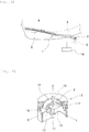
- FIG. 1 is an explanatory view illustrating a configuration of a wiper system 1 according to a first embodiment of the present invention.
- the wiper system 1 includes, as a drive source, a brushless motor 2 (electric motor, hereinafter, abbreviated as "motor 2") having a degree of freedom in three axial directions.
- the wiper system 1 further includes a pivot shaft 3 connected to a rotary shaft of the motor 2, a wiper arm 4 fixed to the pivot shaft 3, and a wiper blade 5 detachably attached to the wiper arm 4.
- the wiper blade 5 is disposed on a windshield glass 6 (hereinafter, abbreviated as "glass 6") of a vehicle.
- the wiper blade 5 is brought into contact with the glass 6 while being pressed by an unillustrated spring mounted in the wiper arm 4.
- the wiper arm 4 swings up and down by normal and reverse rotations of the pivot shaft 3. As the wiper arm 4 swings, the wiper blade 5 also swings and performs wiping operation between upper and lower reversing positions set on the glass 6.
- FIG. 2 is an explanatory view illustrating a configuration of the motor 2 ("Multidimensional actuator” from "SICE (Society of Instrument and Control Engineers Public Interest Incorporated Association) Online Handbook”).
- the motor 2 is a multidimensional actuator constituted of a spherical stator 11 and a semispherical rotor 12.
- the rotor 12 has a rotary shaft 13 and a semispherical rotor core 14 fixed to the rotary shaft 13.
- the rotary shaft 13 is freely-rotatably supported by a bearing 15 and connected to the pivot shaft 3.
- Three coil pairs 16 are arranged in the stator 11. By appropriately controlling an exciting current of each coil 16, it is possible to rotate (Z-axis) or swing (X- and Y-axes) the rotor 12 about X-, Y-, and Z-axes.
- the X- and Y-axes are axes extending in two directions orthogonal to the rotary shaft 13, respectively.
- the motor 2 is a motor (actuator) having a degree of operation freedom in three axial directions and rotatable about the X- and Y-axes. A rotation of the motor 2 about the X-axis causes the wiper blade 5 to rotate about an axis along an extending direction thereof.
- a rotation of the motor 2 about the Y-axis causes the wiper blade 5 to swing in an up-down direction (vertical direction with respect to the glass 6).
- a current to be supplied to each coil 16 is controlled by a controller 18 based on a detection value of a rotating angle sensor 17.
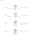
- FIGS. 3A to 3D are explanatory views each illustrating a blade operation in the wiper system 1 of FIG. 1 as viewed from a leading end side thereof.
- the wiper blade 5 operates with an upper side thereof inclined in the travel direction at a position between the upper and lower reversing positions.
- An error angle ⁇ of the wiper blade 5 is maintained by the inclination in the travel direction between the upper and lower reversing positions but is reversed between a forward path (bottom ⁇ top: FIG. 3A ) and a return path (top ⁇ bottom: FIG. 3B ).
- the error angle ⁇ in the forward path is defined as "+ direction" and that in the return path as "-direction".
- the rotation of the motor 2 about the X- and Y-axes is appropriately controlled by the controller 18 depending on a change in a curved surface of the glass 6, a wiping speed, or a travel speed.
- the controller 18 controls an arm pressing force and attitude (error angle or depression angle) of the wiper blade in an optimum condition.
- the motor 2 is made to rotate at that moment about the X-axis (vertical direction with respect to the paper surface of FIGS. 3A to 3D ) to change the inclining direction of the wiper blade 5.
- the error angle ⁇ shifts from the "+ direction” to "- direction” at the upper reversing position ( FIG. 3C ) and from the "- direction” to "+ direction” at the lower reversing position ( FIG. 3D ). That is, the inclining direction (error angle) of the wiper blade is changed immediately to the opposite direction at the upper and lower reversing positions.
- the wiping operation is performed in an attitude suitable for the wiping direction from the start, thereby suppressing occurrence of a wiping defect such as wiping unevenness more surely than when the blade inclination is changed in the middle of the wiping operation after the reversal. Further, it is possible to control the error angle without a complicated mechanism. This can prevent increases in the number of causes of trouble and in the weight of the device and can also realize a compact system, improving layout performance.
- FIG. 4 is an explanatory view illustrating a configuration of a main part of a wiper system 20 according to a second embodiment of the present invention.
- the wiper arm 4 is separated into a base 21 and a leading end portion 22.
- the base 21 is fixed to the pivot shaft 3.
- the leading end portion 22 is attached with the wiper blade 5.
- a rotary support shaft 23 is provided at the base 21 side of the leading end portion 22.
- the rotary support shaft 23 is connected to a rotary shaft of a motor 24 disposed in the base 21 side.
- the motor 24 is actuated, the leading end portion 22 rotates together with the rotary support shaft 23.
- the wiper blade 5 swings.
- the motor 24 is controlled by a controller 25.
- the motor 24 is actuated when the wiper blade 5 reaches the upper and lower reversing positions to change the inclining direction of the wiper blade 5.
- the error angle ⁇ is reversed at the upper and lower reversing positions.
- FIG. 5 is an explanatory view illustrating a configuration of a wiper system 30 according to a third embodiment of the present invention.
- a joint (joint member) 32 is provided between a wiper motor 31 and the pivot shaft 3.
- the joint 32 has a pivot part 33 connected with the pivot shaft 3, a first joint 34 mounted to the pivot part 33 and configured to be swingable about an X-axis (first axis), and a second joint 35 mounted to the first joint 34 and configured to be swingable about a Y-axis (second axis).
- the first joint 34 is swingably mounted to the pivot part 33 by a support shaft (first support shaft) 36.
- the second joint 35 is swingably mounted to the first joint 34 by a support shaft 37 (second support shaft).
- the support shaft 36 and support shaft 37 are fixed, respectively, to the pivot part 33 and the first joint 34.
- a motor 38 (first motor) for rotating the support shaft 36 is housed in the first joint 34.
- a motor 39 (second motor) for rotating the support shaft 37 is housed in the second joint 35.
- Rotational energy of the motor 38 is transmitted to the support shaft 36 by a deceleration mechanism 41.
- Rotational energy of the motor 39 is transmitted to the support shaft 37 by a deceleration mechanism 42.
- the motor 38 is actuated, the pivot part 33 rotates together with the support shaft 36.
- the motor 39 is actuated, the first joint 34 rotates together with the support shaft 37. As a result, the wiper blade 5 starts swinging.
- the motors 38 and 39 are controlled by a controller 43.
- the motor 38 is actuated when the wiper blade 5 reaches the upper and lower reversing positions.
- the joint 32 rotates about the X-axis to change the inclining direction of the wiper blade 5.
- the error angle ⁇ is reversed at the upper and lower reversing positions.
- the wiping operation is performed in an attitude suitable for the wiping direction from the start, thereby suppressing occurrence of a wiping defect such as wiping unevenness.
- the motors 38 and 39 are appropriately controlled according to a change in a curved surface of the glass 6 to thereby allow control of the attitude of the wiper blade 5 in an optimum condition.
- a brushless motor having a degree of freedom in three axial directions is used to change the inclining direction of the wiper blade 5; however, as the drive source for the wiper blade 5, a three-degrees-of-freedom spherical piezoelectric motor can be used in addition to the motor of FIG. 1 .
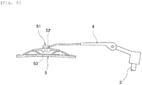
- an operating means like an actuator 51 may be provided at a connection portion between the wiper blade 5 and the wiper arm 4 (see FIG. 6 ).
- the wiper blade 5 is swingably attached to the wiper arm 4 at the connection portion.
- the actuator 51 is constituted of a drive part 52 disposed at the wiper arm 4 side and a swing piece 53 mounted to the wiper blade 5 side. The swing piece 53 is actuated by the drive part 52 to change the error angle of the wiper blade 5.
- the present invention is applied to a parallel-wiping type wiper device in which two wiper blades operate in parallel; however, the present invention may be applied to an opposing-wiping type wiper device in which two wiper blades operate in opposite directions.
Landscapes
- Engineering & Computer Science (AREA)
- Mechanical Engineering (AREA)
- Pivots And Pivotal Connections (AREA)
- Connection Of Motors, Electrical Generators, Mechanical Devices, And The Like (AREA)
Abstract
Description
- The present invention relates to a wiper system mounted on a vehicle such as an automobile and, more particularly, to a technology for optimizing the operating attitude of a wiper blade during wiping of a windshield.
- As a characteristic value governing wiping performance of a wiper device, an error angle indicating an angle between a wiper blade (hereinafter, abbreviated as "blade" as needed) and a windshield. In general, the error angle is set to an angle slightly shifted in such a direction that the blade is dragged from 0 (right angle between a wiping surface and blade) at an intermediate position between blade upper and lower reversing positions. In this case, an inclining direction of the blade in a wiper operation forward path and that of the blade in a wiper operation return path are opposite to each other (error angle setting directions are opposite to each other). It follows that the inclining direction of the blade is reversed after reversal operation, and thereafter the wiping operation is performed in such a way that the blade is dragged.
-
- Patent Document 1:
Japanese UM Application Publication No. No. 3-75063 - Patent Document 2:
Japanese UM Application Publication No. No. 5-56699 - Patent Document 3:
Jpn. Pat. Appln. Laid-Open Publication No. 5-124488 - Patent Document 4:
Japanese UM Application Publication No. 5-15685 - In a conventional wiper system, a wiper arm swings about a single-axis pivot shaft, and the error angle is set based on a mechanical structure as disclosed in
Patent Documents Patent Document 3, a mechanism for changing the error angle in accordance with the wiper arm operation is provided to allow the error angle to be set according to a blade position. However, a wiper system provided with such a mechanism becomes complicated in structure, resulting in an increase in the number of causes of trouble and increase in device weight and cost. - A wiper system control method according to the present invention is a method of controlling the wiper system including a wiper blade for performing a reciprocating wiping operation on a wiping surface and an electric motor for causing the wiper blade to perform the reciprocating wiping operation. The wiper blade operates at error angles different in direction between during a forward-path wiping operation and during a return-path wiping operation. When the wiper blade reaches a reversing position, the error angle is changed.
- In the present invention, an inclining direction of the wiper blade is changed immediately at the upper and lower reversing positions, and even after the operation direction is reversed, the wiping operation is performed in an attitude suitable for a wiping direction from the start. As a result,
it is possible to suppress occurrence of a wiping defect such as wiping unevenness more surely than when the blade inclination is changed in the middle of the wiping operation after the reversal. - In the above wiper system control method, the electric motor may be a motor provided with a rotary shaft for reciprocating the wiper blade, having a degree of operation freedom in three axial directions, and rotatable about axes of two directions orthogonal to the rotary shaft, and when the wiper blade reaches the reversing position, the motor may be made to rotate about one of the two axes about which the motor can rotate that extends in an extending direction of the wiper blade to change the error angle in an opposite direction.
- Further, the wiper system may have a pivot shaft connected to the rotary shaft of the electric motor and a wiper arm fixed to the pivot shaft and attached with the wiper blade, the wiper arm may have a base disposed at the pivot shaft side and operating together with the pivot and a leading portion having a rotary support shaft, rotatably attached to the base by the rotary support shaft, and attached with the wiper blade, the base may have a motor that causes the rotary support shaft to rotate, and when the wiper blade reaches the reversing position, the motor may be made to rotate to change the error angle in an opposite direction.
- Further, the wiper system may have a pivot shaft connected to the rotary shaft of the electric motor through a joint member and a wiper arm attached to the pivot shaft and attached with the wiper blade, the joint member may have a pivot part connected with the pivot shaft, a first joint mounted to the pivot part and configured to be swingable about a first axis orthogonal to the pivot shaft and extending in an extending direction of the wiper blade and a second joint mounted to the first joint and configured to be swingable about a second axis orthogonal to the pivot shaft and the first axis, the first joint may be swingably mounted to the pivot part by a first support shaft fixed to the first joint and disposed along the first axis, and second joint may be swingably mounted to the first joint by a second support shaft fixed to the second joint and disposed along the second axis, a first motor for rotating the first support shaft may be housed in the first joint, and a second motor for rotating the second support shaft may be housed in the second joint, and when the wiper blade reaches the reversing position, the first motor may be made to rotate to rotate the joint member about the first axis to change the error angle in an opposite direction.
- A wiper system according to the present invention includes a wiper blade for performing a reciprocating wiping operation on a wiping surface and an electric motor for causing the wiper blade to perform the reciprocating wiping operation. The wiper system includes a controller that makes the wiper blade operate at error angles different in direction between during a forward-path wiping operation and during a return-path wiping operation and changes the error angle when the wiper blade reaches a reversing position.
- In the present invention, an inclining direction of the wiper blade is changed immediately at the upper and lower reversing positions by the controller, and even after the operation direction of the wiper blade is reversed, the wiping operation is performed in an attitude suitable for a wiping direction from the start. As a result, it is possible to suppress occurrence of a wiping defect such as wiping unevenness more surely than when the blade inclination is changed in the middle of the wiping operation after the reversal.
- In the above wiper system, the electric motor may be a motor provided with a rotary shaft for reciprocating the wiper blade, having a degree of operation freedom in three axial directions, and rotatable about axes of two directions orthogonal to the rotary shaft, and the controller may rotate the motor about one of the two axes about which the motor can rotate that extends in an extending direction of the wiper blade when the wiper blade reaches the reversing position to change the error angle in an opposite direction.
- Further, the wiper system may have a pivot shaft connected to the rotary shaft of the electric motor and a wiper arm fixed to the pivot shaft and attached with the wiper blade, the wiper arm may have a base disposed at the pivot shaft side and operating together with the pivot and a leading portion having a rotary support shaft, rotatably attached to the base by the rotary support shaft, and attached with the wiper blade, the base may have a motor that causes the rotary support shaft to rotate, and the controller may rotate the motor when the wiper blade reaches the reversing position to change the error angle in an opposite direction.
- Further, the wiper system may have a pivot shaft connected to the rotary shaft of the electric motor through a joint member and a wiper arm attached to the pivot shaft and attached with the wiper blade, the joint member may have a pivot part connected with the pivot shaft, a first joint mounted to the pivot part and configured to be swingable about a first axis orthogonal to the pivot shaft and extending in an extending direction of the wiper blade, and a second joint mounted to the first joint and configured to be swingable about a second axis orthogonal to the pivot shaft and first axis, the first joint may be swingably mounted to the pivot part by a first support shaft fixed to the first joint and disposed along the first axis, and the second joint may be swingably mounted to the first joint by a second support shaft fixed to the second joint and disposed along the second axis, a first motor for rotating the first support shaft may be housed in the first joint, and a second motor for rotating the second support shaft may be housed in the second joint, and the controller may rotate the first motor when the wiper blade reaches the reversing position to rotate the joint member about the first axis to change the error angle in an opposite direction.
- According to the wiper system control method of the present invention, the wiper blade is made to operate at error angles different in direction between during a forward-path wiping operation and during a return-path wiping operation, and when the wiper blade reaches a reversing position, the error angle is changed. With this configuration, an inclining direction of the wiper blade is changed immediately at the upper and lower reversing positions. As a result, even after the operation direction of the wiper blade is reversed, the wiping operation is performed in an attitude suitable for a wiping direction from the start. Thus, it is possible to suppress occurrence of a wiping defect such as wiping unevenness more surely than when the blade inclination is changed in the middle of the wiping operation after the reversal. Further, it is possible to control the error angle without a complicated mechanism. This can prevent increases in the number of causes of trouble and in the weight of the device and can also realize a compact system, improving layout performance.
- According to the wiper system of the present invention, there is provided a controller that makes the wiper blade operate at error angles different in direction between during a forward-path wiping operation and during a return-path wiping operation and changes the error angle when the wiper blade reaches a reversing position. With this configuration, an inclining direction of the wiper blade is changed immediately at the upper and lower reversing positions. As a result, even after the operation direction of the wiper blade is reversed, the wiping operation is performed in an attitude suitable for a wiping direction from the start. Thus, it is possible to suppress occurrence of a wiping defect such as wiping unevenness more surely than when the blade inclination is changed in the middle of the wiping operation after the reversal. Further, it is possible to control the error angle without a complicated mechanism. This can prevent increases in the number of causes of trouble and in the weight of the device and can also realize a compact system, improving layout performance.
-
-
FIG. 1 is an explanatory view illustrating a configuration of a wiper system according to a first embodiment of the present invention. -
FIG. 2 is an explanatory view illustrating a configuration of a motor used in the wiper system ofFIG. 1 ; -
FIGS. 3A to 3D are explanatory views each illustrating a blade operation in the wiper system ofFIG. 1 . -
FIG. 4 is an explanatory view illustrating a configuration of a main part of a wiper system according to a second embodiment of the present invention. -
FIG. 5 is an explanatory view illustrating a configuration of a joint used in a wiper system according to a third embodiment of the present invention. -
FIG. 6 is an explanatory view illustrating another example of a mechanism for changing an error angle of a wiper blade. - The object of the following embodiments is to optimize an operating attitude of a wiper blade during a wiping operation without adding a complicated mechanism to realize a stable wiping operation.
- Hereinafter, embodiments of the present invention will be described in detail with reference to the drawings.
FIG. 1 is an explanatory view illustrating a configuration of awiper system 1 according to a first embodiment of the present invention. As illustrated inFIG. 1 , thewiper system 1 includes, as a drive source, a brushless motor 2 (electric motor, hereinafter, abbreviated as "motor 2") having a degree of freedom in three axial directions. Thewiper system 1 further includes apivot shaft 3 connected to a rotary shaft of themotor 2, awiper arm 4 fixed to thepivot shaft 3, and awiper blade 5 detachably attached to thewiper arm 4. Thewiper blade 5 is disposed on a windshield glass 6 (hereinafter, abbreviated as "glass 6") of a vehicle. Thewiper blade 5 is brought into contact with theglass 6 while being pressed by an unillustrated spring mounted in thewiper arm 4. Thewiper arm 4 swings up and down by normal and reverse rotations of thepivot shaft 3. As thewiper arm 4 swings, thewiper blade 5 also swings and performs wiping operation between upper and lower reversing positions set on theglass 6. - In the
wiper system 1, the three degree-of-freedom motor is used as a drive source of the wiper arm to perform a wiping operation while constantly inclining the blade in a travel direction to thereby stabilize the wiping operation.FIG. 2 is an explanatory view illustrating a configuration of the motor 2 ("Multidimensional actuator" from "SICE (Society of Instrument and Control Engineers Public Interest Incorporated Association) Online Handbook"). Themotor 2 is a multidimensional actuator constituted of aspherical stator 11 and asemispherical rotor 12. Therotor 12 has arotary shaft 13 and asemispherical rotor core 14 fixed to therotary shaft 13. Therotary shaft 13 is freely-rotatably supported by abearing 15 and connected to thepivot shaft 3. - Three coil pairs 16 are arranged in the
stator 11. By appropriately controlling an exciting current of eachcoil 16, it is possible to rotate (Z-axis) or swing (X- and Y-axes) therotor 12 about X-, Y-, and Z-axes. The X- and Y-axes are axes extending in two directions orthogonal to therotary shaft 13, respectively. Themotor 2 is a motor (actuator) having a degree of operation freedom in three axial directions and rotatable about the X- and Y-axes. A rotation of themotor 2 about the X-axis causes thewiper blade 5 to rotate about an axis along an extending direction thereof. A rotation of themotor 2 about the Y-axis causes thewiper blade 5 to swing in an up-down direction (vertical direction with respect to the glass 6). A current to be supplied to eachcoil 16 is controlled by acontroller 18 based on a detection value of arotating angle sensor 17. -
FIGS. 3A to 3D are explanatory views each illustrating a blade operation in thewiper system 1 ofFIG. 1 as viewed from a leading end side thereof. As illustrated inFIGS. 3A to 3D , in thewiper system 1, thewiper blade 5 operates with an upper side thereof inclined in the travel direction at a position between the upper and lower reversing positions. An error angle θ of thewiper blade 5 is maintained by the inclination in the travel direction between the upper and lower reversing positions but is reversed between a forward path (bottom → top:FIG. 3A ) and a return path (top → bottom:FIG. 3B ). Here, the error angle θ in the forward path is defined as "+ direction" and that in the return path as "-direction". In thewiper system 1, the rotation of themotor 2 about the X- and Y-axes is appropriately controlled by thecontroller 18 depending on a change in a curved surface of theglass 6, a wiping speed, or a travel speed. Thecontroller 18 controls an arm pressing force and attitude (error angle or depression angle) of the wiper blade in an optimum condition. - When the
wiper blade 5 reaches the upper and lower reversing positions, themotor 2 is made to rotate at that moment about the X-axis (vertical direction with respect to the paper surface ofFIGS. 3A to 3D ) to change the inclining direction of thewiper blade 5. As a result, the error angle θ shifts from the "+ direction" to "- direction" at the upper reversing position (FIG. 3C ) and from the "- direction" to "+ direction" at the lower reversing position (FIG. 3D ). That is, the inclining direction (error angle) of the wiper blade is changed immediately to the opposite direction at the upper and lower reversing positions. Thus, even after the operation direction is reversed, the wiping operation is performed in an attitude suitable for the wiping direction from the start, thereby suppressing occurrence of a wiping defect such as wiping unevenness more surely than when the blade inclination is changed in the middle of the wiping operation after the reversal. Further, it is possible to control the error angle without a complicated mechanism. This can prevent increases in the number of causes of trouble and in the weight of the device and can also realize a compact system, improving layout performance. -
FIG. 4 is an explanatory view illustrating a configuration of a main part of awiper system 20 according to a second embodiment of the present invention. In the description of the following embodiments, the same reference numerals are given to the same components and portions as in the first embodiment and descriptions thereof will be omitted. As illustrated inFIG. 4 , in the second embodiment, thewiper arm 4 is separated into abase 21 and aleading end portion 22. Thebase 21 is fixed to thepivot shaft 3. Theleading end portion 22 is attached with thewiper blade 5. Arotary support shaft 23 is provided at the base 21 side of theleading end portion 22. Therotary support shaft 23 is connected to a rotary shaft of amotor 24 disposed in the base 21 side. When themotor 24 is actuated, theleading end portion 22 rotates together with therotary support shaft 23. As themotor 24 rotates, thewiper blade 5 swings. Themotor 24 is controlled by acontroller 25. - In the
wiper system 20, themotor 24 is actuated when thewiper blade 5 reaches the upper and lower reversing positions to change the inclining direction of thewiper blade 5. As a result, the error angle θ is reversed at the upper and lower reversing positions. Thus, as described above, even after the operation direction is reversed, the wiping operation is performed in an attitude suitable for the wiping direction from the start, thereby suppressing occurrence of a wiping defect such as wiping unevenness. Further, it is possible to control the error angle without a complicated mechanism. This can prevent increases in the number of causes of trouble and in the weight of the device and can also realize a compact system, improving layout performance. -
FIG. 5 is an explanatory view illustrating a configuration of awiper system 30 according to a third embodiment of the present invention. As illustrated inFIG. 5 , in the present embodiment, a joint (joint member) 32 is provided between awiper motor 31 and thepivot shaft 3. The joint 32 has apivot part 33 connected with thepivot shaft 3, a first joint 34 mounted to thepivot part 33 and configured to be swingable about an X-axis (first axis), and a second joint 35 mounted to the first joint 34 and configured to be swingable about a Y-axis (second axis). The first joint 34 is swingably mounted to thepivot part 33 by a support shaft (first support shaft) 36. The second joint 35 is swingably mounted to the first joint 34 by a support shaft 37 (second support shaft). Thesupport shaft 36 andsupport shaft 37 are fixed, respectively, to thepivot part 33 and the first joint 34. - A motor 38 (first motor) for rotating the
support shaft 36 is housed in the first joint 34. A motor 39 (second motor) for rotating thesupport shaft 37 is housed in the second joint 35. Rotational energy of themotor 38 is transmitted to thesupport shaft 36 by adeceleration mechanism 41. Rotational energy of themotor 39 is transmitted to thesupport shaft 37 by adeceleration mechanism 42. When themotor 38 is actuated, thepivot part 33 rotates together with thesupport shaft 36. When themotor 39 is actuated, the first joint 34 rotates together with thesupport shaft 37. As a result, thewiper blade 5 starts swinging. Themotors controller 43. - In the
wiper system 30, themotor 38 is actuated when thewiper blade 5 reaches the upper and lower reversing positions. When themotor 38 is actuated, the joint 32 rotates about the X-axis to change the inclining direction of thewiper blade 5. As a result, the error angle θ is reversed at the upper and lower reversing positions. Thus, as described above, even after the operation direction is reversed, the wiping operation is performed in an attitude suitable for the wiping direction from the start, thereby suppressing occurrence of a wiping defect such as wiping unevenness. Further, it is possible to control the error angle without a complicated mechanism. This can prevent increases in the number of causes of trouble and in the weight of the device and can also realize a compact system, improving layout performance. Also in thewiper system 30, themotors glass 6 to thereby allow control of the attitude of thewiper blade 5 in an optimum condition. - The present invention is not limited to the embodiments as described above and may be variously modified without departing from the scope of the invention.
- For example, in the above embodiments, a brushless motor (actuator) having a degree of freedom in three axial directions is used to change the inclining direction of the
wiper blade 5; however, as the drive source for thewiper blade 5, a three-degrees-of-freedom spherical piezoelectric motor can be used in addition to the motor ofFIG. 1 . - Further, as a mechanism that moves the
wiper blade 5 left and right to change the error angle when thewiper blade 5 reaches the reversing position, an operating means like anactuator 51 may be provided at a connection portion between thewiper blade 5 and the wiper arm 4 (seeFIG. 6 ). In this case, thewiper blade 5 is swingably attached to thewiper arm 4 at the connection portion. Theactuator 51 is constituted of adrive part 52 disposed at thewiper arm 4 side and aswing piece 53 mounted to thewiper blade 5 side. Theswing piece 53 is actuated by thedrive part 52 to change the error angle of thewiper blade 5. - In the wiper system of the embodiments described above, the present invention is applied to a parallel-wiping type wiper device in which two wiper blades operate in parallel; however, the present invention may be applied to an opposing-wiping type wiper device in which two wiper blades operate in opposite directions.
-
- 1:
- Wiper system
- 2:
- Brushless motor
- 3:
- Pivot shaft
- 4:
- Wiper arm
- 5:
- Wiper blade
- 6:
- Windshield glass
- 11:
- Stator
- 12:
- Rotor
- 13:
- Rotary shaft
- 14:
- Rotor core
- 15:
- Bearing
- 16:
- Coil
- 17:
- Rotating angle sensor
- 20:
- Wiper system
- 21:
- Base
- 22:
- Leading end portion
- 23:
- Rotary support shaft
- 24:
- Motor
- 30:
- Wiper system
- 31:
- Wiper motor
- 32:
- Joint
- 33:
- Pivot part
- 34:
- First joint
- 35:
- Second joint
- 36:
- Support shaft (first support shaft)
- 37:
- Support shaft (second support shaft)
- 38:
- Motor (first motor)
- 39:
- Motor (second motor)
- 41:
- Deceleration mechanism
- 42:
- Deceleration mechanism
- 51:
- Actuator
- 52:
- Drive part
- 53:
- Swing piece
- θ:
- Error angle
Claims (8)
- A control method for a wiper system, the wiper system including a wiper blade for performing a reciprocating wiping operation on a wiping surface and an electric motor for causing the wiper blade to perform the reciprocating wiping operation, wherein
the wiper blade operates at error angles different in direction between during a forward-path wiping operation and during a return-path wiping operation, and
when the wiper blade reaches a reversing position, the error angle is changed. - The wiper system control method according to claim 1, wherein
the electric motor is a motor provided with a rotary shaft for reciprocating the wiper blade, having a degree of operation freedom in three axial directions, and rotatable about axes of two directions orthogonal to the rotary shaft, and
when the wiper blade reaches the reversing position, the motor is made to rotate about one of the two axes about which the motor can rotate that extends in an extending direction of the wiper blade to change the error angle in an opposite direction. - The wiper system control method according to claim 1, wherein
the wiper system has a pivot shaft connected to the rotary shaft of the electric motor and a wiper arm fixed to the pivot shaft and attached with the wiper blade,
the wiper arm has a base disposed at the pivot shaft side and operating together with the pivot shaft and a leading portion having a rotary support shaft, rotatably attached to the base by the rotary support shaft, and attached with the wiper blade,
the base has a motor that causes the rotary support shaft to rotate, and
when the wiper blade reaches the reversing position, the motor is made to rotate to change the error angle in an opposite direction. - The wiper system control method according to claim 1, wherein
the wiper system has a pivot shaft connected to the rotary shaft of the electric motor through a joint member and a wiper arm attached to the pivot shaft and attached with the wiper blade,
the joint member has a pivot part connected with the pivot shaft, a first joint mounted to the pivot part and configured to be swingable about a first axis orthogonal to the pivot shaft and extending in an extending direction of the wiper blade and a second joint mounted to the first joint and configured to be swingable about a second axis orthogonal to the pivot shaft and the first axis,
the first joint is swingably mounted to the pivot part by a first support shaft fixed to the first joint and disposed along the first axis, and the second joint is swingably mounted to the first joint by a second support shaft fixed to the second joint and disposed along the second axis,
a first motor for rotating the first support shaft is housed in the first joint, and a second motor for rotating the second support shaft is housed in the second joint, and
when the wiper blade reaches the reversing position, the first motor is made to rotate to rotate the joint member about the first axis to change the error angle in an opposite direction. - A wiper system including a wiper blade for performing a reciprocating wiping operation on a wiping surface and an electric motor for causing the wiper blade to perform the reciprocating wiping operation, wherein
the wiper system comprises a controller that makes the wiper blade operate at error angles different in direction between during a forward-path wiping operation and during a return-path wiping operation and changes the error angle when the wiper blade reaches a reversing position. - The wiper system according to claim 5, wherein the electric motor is a motor provided with a rotary shaft for reciprocating the wiper blade, having a degree of operation freedom in three axial directions, and rotatable about axes of two directions orthogonal to the rotary shaft, and
the controller rotates the motor about one of the two axes about which the motor can rotate that extends in an extending direction of the wiper blade when the wiper blade reaches the reversing position to change the error angle in an opposite direction. - The wiper system according to claim 5, wherein
the wiper system has a pivot shaft connected to the rotary shaft of the electric motor and a wiper arm fixed to the pivot shaft and attached with the wiper blade,
the wiper arm has a base disposed at the pivot shaft side and operating together with the pivot shaft and a leading portion having a rotary support shaft, rotatably attached to the base by the rotary support shaft, and attached with the wiper blade,
the base has a motor that causes the rotary support shaft to rotate, and
the controller rotates the motor when the wiper blade reaches the reversing position to change the error angle in an opposite direction. - The wiper system according to claim 5, wherein
the wiper system has a pivot shaft connected to the rotary shaft of the electric motor through a joint member and a wiper arm attached to the pivot shaft and attached with the wiper blade,
the joint member has a pivot part connected with the pivot shaft, a first joint mounted to the pivot part and configured to be swingable about a first axis orthogonal to the pivot shaft and extending in an extending direction of the wiper blade and a second joint mounted to the first joint and configured to be swingable about a second axis orthogonal to the pivot shaft and the first axis,
the first joint is swingably mounted to the pivot part by a first support shaft fixed to the first joint and disposed along the first axis, and the second joint is swingably mounted to the first joint by a second support shaft fixed to the second joint and disposed along the second axis,
a first motor for rotating the first support shaft is housed in the first joint, and a second motor for rotating the second support shaft is housed in the second joint, and
the controller rotates the first motor when the wiper blade reaches the reversing position to rotate the joint member about the first axis to change the error angle in an opposite direction.
Applications Claiming Priority (2)
| Application Number | Priority Date | Filing Date | Title |
|---|---|---|---|
| JP2014066254A JP6393054B2 (en) | 2014-03-27 | 2014-03-27 | Wiper system control method and wiper system |
| PCT/JP2015/058634 WO2015146867A1 (en) | 2014-03-27 | 2015-03-21 | Method for controlling wiper system, and wiper system |
Publications (3)
| Publication Number | Publication Date |
|---|---|
| EP3124337A1 true EP3124337A1 (en) | 2017-02-01 |
| EP3124337A4 EP3124337A4 (en) | 2017-11-22 |
| EP3124337B1 EP3124337B1 (en) | 2018-10-03 |
Family
ID=54195382
Family Applications (1)
| Application Number | Title | Priority Date | Filing Date |
|---|---|---|---|
| EP15767736.0A Not-in-force EP3124337B1 (en) | 2014-03-27 | 2015-03-21 | Method for controlling wiper system, and wiper system |
Country Status (4)
| Country | Link |
|---|---|
| US (1) | US10086798B2 (en) |
| EP (1) | EP3124337B1 (en) |
| JP (1) | JP6393054B2 (en) |
| WO (1) | WO2015146867A1 (en) |
Cited By (1)
| Publication number | Priority date | Publication date | Assignee | Title |
|---|---|---|---|---|
| FR3062830A1 (en) * | 2017-02-16 | 2018-08-17 | Valeo Systemes D'essuyage | DEVICE FOR DRIVING ROTATION OF A WIPER ARM, IN PARTICULAR FOR A PANORAMIC WINDSHIELD |
Families Citing this family (3)
| Publication number | Priority date | Publication date | Assignee | Title |
|---|---|---|---|---|
| SE540687C2 (en) * | 2016-06-15 | 2018-10-09 | Scania Cv Ab | Windshield wiper device, and a method for wiping a windshield |
| CN107839652A (en) * | 2016-09-20 | 2018-03-27 | 台州法雷奥温岭汽车零部件有限公司 | Wiper system and the vehicle with Wiper system |
| SE540789C2 (en) * | 2017-04-28 | 2018-11-13 | Scania Cv Ab | Windshield wiper device for a motor vehicle and a method for wiping a windshield |
Family Cites Families (20)
| Publication number | Priority date | Publication date | Assignee | Title |
|---|---|---|---|---|
| JPS60122266U (en) * | 1984-01-24 | 1985-08-17 | マツダ株式会社 | car wiper device |
| JPS6268159A (en) * | 1985-09-18 | 1987-03-28 | Honda Motor Co Ltd | Windshield wiper device |
| JPS62116341A (en) * | 1985-11-15 | 1987-05-27 | Nippon Soken Inc | Wiper device for vehicle |
| JPH0723082B2 (en) * | 1986-02-13 | 1995-03-15 | 株式会社日本自動車部品総合研究所 | Wiper device |
| JPH059971Y2 (en) * | 1987-06-15 | 1993-03-11 | ||
| DE3824489A1 (en) * | 1988-07-20 | 1990-01-25 | Bosch Gmbh Robert | WIPING DEVICE FOR CURVED WINDOWS OF MOTOR VEHICLES |
| JPH0653160B2 (en) | 1989-08-18 | 1994-07-20 | 呉羽化学工業株式会社 | Beat generation method and device |
| JPH0515685A (en) | 1991-07-11 | 1993-01-26 | Sharp Corp | Controlling device for washing machine |
| JPH0556699A (en) | 1991-08-22 | 1993-03-05 | Meidensha Corp | Parallel/parallel-off control system for a plurality of generators |
| JPH05124488A (en) | 1991-11-01 | 1993-05-21 | Asmo Co Ltd | Wiper device |
| FR2686848A1 (en) * | 1992-02-04 | 1993-08-06 | Peugeot | Windscreen wiper with orientable blade |
| JP3006386B2 (en) * | 1993-12-28 | 2000-02-07 | 三菱自動車エンジニアリング株式会社 | Wiper device |
| JP3006385B2 (en) * | 1993-12-28 | 2000-02-07 | 三菱自動車エンジニアリング株式会社 | Wiper device |
| JPH07205766A (en) * | 1994-01-26 | 1995-08-08 | Mitsubishi Automob Eng Co Ltd | Wiper device |
| EP0806330A3 (en) * | 1996-05-09 | 1998-11-04 | Bayerische Motoren Werke Aktiengesellschaft, Patentabteilung AJ-3 | Wiper device for a vehicle windscreen |
| FR2757815B1 (en) * | 1996-12-31 | 1999-03-26 | Peugeot | DEVICE FOR THE CONTINUOUS ADJUSTMENT OF THE ANGLE OF INCIDENCE OF A SQUEEGEE OF A WINDSCREEN WIPER OF A MOTOR VEHICLE |
| FR2857317B1 (en) * | 2003-07-11 | 2006-08-18 | Peugeot Citroen Automobiles Sa | ACTIVE WIPER SYSTEM |
| CN100540367C (en) * | 2004-03-31 | 2009-09-16 | 株式会社美姿把 | Wiper control method |
| JP4905097B2 (en) * | 2006-12-06 | 2012-03-28 | 株式会社デンソー | Raindrop detector |
| US8819888B2 (en) * | 2012-06-22 | 2014-09-02 | Mitsuba Corporation | Wiper apparatus |
-
2014
- 2014-03-27 JP JP2014066254A patent/JP6393054B2/en not_active Expired - Fee Related
-
2015
- 2015-03-21 WO PCT/JP2015/058634 patent/WO2015146867A1/en not_active Ceased
- 2015-03-21 US US15/127,130 patent/US10086798B2/en not_active Expired - Fee Related
- 2015-03-21 EP EP15767736.0A patent/EP3124337B1/en not_active Not-in-force
Cited By (4)
| Publication number | Priority date | Publication date | Assignee | Title |
|---|---|---|---|---|
| FR3062830A1 (en) * | 2017-02-16 | 2018-08-17 | Valeo Systemes D'essuyage | DEVICE FOR DRIVING ROTATION OF A WIPER ARM, IN PARTICULAR FOR A PANORAMIC WINDSHIELD |
| EP3363695A1 (en) * | 2017-02-16 | 2018-08-22 | Valeo Systèmes d'Essuyage | Drive device for driving the rotation of a wiper arm, particularly for a panoramic windscreen |
| CN108437935A (en) * | 2017-02-16 | 2018-08-24 | 法雷奥系统公司 | Driving device for driving the Wiper arm of especially panorama windscreen to rotate |
| CN108437935B (en) * | 2017-02-16 | 2021-07-13 | 法雷奥系统公司 | Drive device for driving a wiper arm, in particular a panoramic windscreen, in rotation |
Also Published As
| Publication number | Publication date |
|---|---|
| US10086798B2 (en) | 2018-10-02 |
| JP2015189271A (en) | 2015-11-02 |
| EP3124337A4 (en) | 2017-11-22 |
| JP6393054B2 (en) | 2018-09-19 |
| EP3124337B1 (en) | 2018-10-03 |
| US20170106837A1 (en) | 2017-04-20 |
| WO2015146867A1 (en) | 2015-10-01 |
Similar Documents
| Publication | Publication Date | Title |
|---|---|---|
| US10086798B2 (en) | Wiper system control method and wiper system | |
| EP2586702B1 (en) | Compact two axis gimbal for control stick | |
| JP6623763B2 (en) | Vehicle wiper device | |
| CN102282071B (en) | Improved rotor blade control system and method | |
| JP7020279B2 (en) | Flyers and how to control them | |
| EP2631034B1 (en) | Power Tool | |
| US20080209663A1 (en) | Windshield Wiping Device and Method for the Operation Thereof | |
| JP2021144266A5 (en) | ||
| EP2738052A1 (en) | Motor control device | |
| JP2019528931A5 (en) | ||
| JP2007143278A (en) | Wiper motor | |
| JP5225600B2 (en) | Electric motor | |
| JP5097759B2 (en) | Wiper motor | |
| JP5715098B2 (en) | Wiper motor | |
| JP5619832B2 (en) | Wiper motor | |
| JP2017007544A (en) | Vehicle wiper device | |
| JP2010022200A (en) | Wiper motor | |
| CN101978170A (en) | Device for changing a pitch of a blade of an impeller/propeller and a fan comprising the device | |
| FR3114927B1 (en) | a device for rotating at least one shaft, a machine tool and a rolling machine equipped with such a device | |
| JP5155981B2 (en) | Motor with reduction mechanism | |
| JP4981420B2 (en) | Electric motor with reduction mechanism | |
| KR20190006555A (en) | Windshield wiper device | |
| JP4499294B2 (en) | Wiper device | |
| JP2017007545A (en) | Vehicle wiper device | |
| JP2019051904A (en) | Vehicle wiper device |
Legal Events
| Date | Code | Title | Description |
|---|---|---|---|
| STAA | Information on the status of an ep patent application or granted ep patent |
Free format text: STATUS: THE INTERNATIONAL PUBLICATION HAS BEEN MADE |
|
| PUAI | Public reference made under article 153(3) epc to a published international application that has entered the european phase |
Free format text: ORIGINAL CODE: 0009012 |
|
| STAA | Information on the status of an ep patent application or granted ep patent |
Free format text: STATUS: REQUEST FOR EXAMINATION WAS MADE |
|
| 17P | Request for examination filed |
Effective date: 20160926 |
|
| AK | Designated contracting states |
Kind code of ref document: A1 Designated state(s): AL AT BE BG CH CY CZ DE DK EE ES FI FR GB GR HR HU IE IS IT LI LT LU LV MC MK MT NL NO PL PT RO RS SE SI SK SM TR |
|
| AX | Request for extension of the european patent |
Extension state: BA ME |
|
| DAV | Request for validation of the european patent (deleted) | ||
| DAX | Request for extension of the european patent (deleted) | ||
| A4 | Supplementary search report drawn up and despatched |
Effective date: 20171020 |
|
| RIC1 | Information provided on ipc code assigned before grant |
Ipc: B60S 1/44 20060101AFI20171016BHEP Ipc: B60S 1/08 20060101ALI20171016BHEP |
|
| GRAP | Despatch of communication of intention to grant a patent |
Free format text: ORIGINAL CODE: EPIDOSNIGR1 |
|
| STAA | Information on the status of an ep patent application or granted ep patent |
Free format text: STATUS: GRANT OF PATENT IS INTENDED |
|
| INTG | Intention to grant announced |
Effective date: 20180620 |
|
| GRAS | Grant fee paid |
Free format text: ORIGINAL CODE: EPIDOSNIGR3 |
|
| GRAA | (expected) grant |
Free format text: ORIGINAL CODE: 0009210 |
|
| STAA | Information on the status of an ep patent application or granted ep patent |
Free format text: STATUS: THE PATENT HAS BEEN GRANTED |
|
| AK | Designated contracting states |
Kind code of ref document: B1 Designated state(s): AL AT BE BG CH CY CZ DE DK EE ES FI FR GB GR HR HU IE IS IT LI LT LU LV MC MK MT NL NO PL PT RO RS SE SI SK SM TR |
|
| REG | Reference to a national code |
Ref country code: GB Ref legal event code: FG4D |
|
| REG | Reference to a national code |
Ref country code: CH Ref legal event code: EP Ref country code: AT Ref legal event code: REF Ref document number: 1048254 Country of ref document: AT Kind code of ref document: T Effective date: 20181015 |
|
| REG | Reference to a national code |
Ref country code: IE Ref legal event code: FG4D Ref country code: DE Ref legal event code: R096 Ref document number: 602015017573 Country of ref document: DE |
|
| REG | Reference to a national code |
Ref country code: NL Ref legal event code: MP Effective date: 20181003 |
|
| REG | Reference to a national code |
Ref country code: LT Ref legal event code: MG4D |
|
| REG | Reference to a national code |
Ref country code: AT Ref legal event code: MK05 Ref document number: 1048254 Country of ref document: AT Kind code of ref document: T Effective date: 20181003 |
|
| PG25 | Lapsed in a contracting state [announced via postgrant information from national office to epo] |
Ref country code: NL Free format text: LAPSE BECAUSE OF FAILURE TO SUBMIT A TRANSLATION OF THE DESCRIPTION OR TO PAY THE FEE WITHIN THE PRESCRIBED TIME-LIMIT Effective date: 20181003 |
|
| PG25 | Lapsed in a contracting state [announced via postgrant information from national office to epo] |
Ref country code: ES Free format text: LAPSE BECAUSE OF FAILURE TO SUBMIT A TRANSLATION OF THE DESCRIPTION OR TO PAY THE FEE WITHIN THE PRESCRIBED TIME-LIMIT Effective date: 20181003 Ref country code: CZ Free format text: LAPSE BECAUSE OF FAILURE TO SUBMIT A TRANSLATION OF THE DESCRIPTION OR TO PAY THE FEE WITHIN THE PRESCRIBED TIME-LIMIT Effective date: 20181003 Ref country code: NO Free format text: LAPSE BECAUSE OF FAILURE TO SUBMIT A TRANSLATION OF THE DESCRIPTION OR TO PAY THE FEE WITHIN THE PRESCRIBED TIME-LIMIT Effective date: 20190103 Ref country code: AT Free format text: LAPSE BECAUSE OF FAILURE TO SUBMIT A TRANSLATION OF THE DESCRIPTION OR TO PAY THE FEE WITHIN THE PRESCRIBED TIME-LIMIT Effective date: 20181003 Ref country code: FI Free format text: LAPSE BECAUSE OF FAILURE TO SUBMIT A TRANSLATION OF THE DESCRIPTION OR TO PAY THE FEE WITHIN THE PRESCRIBED TIME-LIMIT Effective date: 20181003 Ref country code: IS Free format text: LAPSE BECAUSE OF FAILURE TO SUBMIT A TRANSLATION OF THE DESCRIPTION OR TO PAY THE FEE WITHIN THE PRESCRIBED TIME-LIMIT Effective date: 20190203 Ref country code: BG Free format text: LAPSE BECAUSE OF FAILURE TO SUBMIT A TRANSLATION OF THE DESCRIPTION OR TO PAY THE FEE WITHIN THE PRESCRIBED TIME-LIMIT Effective date: 20190103 Ref country code: LT Free format text: LAPSE BECAUSE OF FAILURE TO SUBMIT A TRANSLATION OF THE DESCRIPTION OR TO PAY THE FEE WITHIN THE PRESCRIBED TIME-LIMIT Effective date: 20181003 Ref country code: HR Free format text: LAPSE BECAUSE OF FAILURE TO SUBMIT A TRANSLATION OF THE DESCRIPTION OR TO PAY THE FEE WITHIN THE PRESCRIBED TIME-LIMIT Effective date: 20181003 Ref country code: PL Free format text: LAPSE BECAUSE OF FAILURE TO SUBMIT A TRANSLATION OF THE DESCRIPTION OR TO PAY THE FEE WITHIN THE PRESCRIBED TIME-LIMIT Effective date: 20181003 Ref country code: LV Free format text: LAPSE BECAUSE OF FAILURE TO SUBMIT A TRANSLATION OF THE DESCRIPTION OR TO PAY THE FEE WITHIN THE PRESCRIBED TIME-LIMIT Effective date: 20181003 |
|
| PG25 | Lapsed in a contracting state [announced via postgrant information from national office to epo] |
Ref country code: RS Free format text: LAPSE BECAUSE OF FAILURE TO SUBMIT A TRANSLATION OF THE DESCRIPTION OR TO PAY THE FEE WITHIN THE PRESCRIBED TIME-LIMIT Effective date: 20181003 Ref country code: SE Free format text: LAPSE BECAUSE OF FAILURE TO SUBMIT A TRANSLATION OF THE DESCRIPTION OR TO PAY THE FEE WITHIN THE PRESCRIBED TIME-LIMIT Effective date: 20181003 Ref country code: AL Free format text: LAPSE BECAUSE OF FAILURE TO SUBMIT A TRANSLATION OF THE DESCRIPTION OR TO PAY THE FEE WITHIN THE PRESCRIBED TIME-LIMIT Effective date: 20181003 Ref country code: PT Free format text: LAPSE BECAUSE OF FAILURE TO SUBMIT A TRANSLATION OF THE DESCRIPTION OR TO PAY THE FEE WITHIN THE PRESCRIBED TIME-LIMIT Effective date: 20190203 Ref country code: GR Free format text: LAPSE BECAUSE OF FAILURE TO SUBMIT A TRANSLATION OF THE DESCRIPTION OR TO PAY THE FEE WITHIN THE PRESCRIBED TIME-LIMIT Effective date: 20190104 |
|
| REG | Reference to a national code |
Ref country code: DE Ref legal event code: R097 Ref document number: 602015017573 Country of ref document: DE |
|
| PG25 | Lapsed in a contracting state [announced via postgrant information from national office to epo] |
Ref country code: DK Free format text: LAPSE BECAUSE OF FAILURE TO SUBMIT A TRANSLATION OF THE DESCRIPTION OR TO PAY THE FEE WITHIN THE PRESCRIBED TIME-LIMIT Effective date: 20181003 Ref country code: IT Free format text: LAPSE BECAUSE OF FAILURE TO SUBMIT A TRANSLATION OF THE DESCRIPTION OR TO PAY THE FEE WITHIN THE PRESCRIBED TIME-LIMIT Effective date: 20181003 |
|
| PLBE | No opposition filed within time limit |
Free format text: ORIGINAL CODE: 0009261 |
|
| STAA | Information on the status of an ep patent application or granted ep patent |
Free format text: STATUS: NO OPPOSITION FILED WITHIN TIME LIMIT |
|
| PG25 | Lapsed in a contracting state [announced via postgrant information from national office to epo] |
Ref country code: RO Free format text: LAPSE BECAUSE OF FAILURE TO SUBMIT A TRANSLATION OF THE DESCRIPTION OR TO PAY THE FEE WITHIN THE PRESCRIBED TIME-LIMIT Effective date: 20181003 Ref country code: EE Free format text: LAPSE BECAUSE OF FAILURE TO SUBMIT A TRANSLATION OF THE DESCRIPTION OR TO PAY THE FEE WITHIN THE PRESCRIBED TIME-LIMIT Effective date: 20181003 Ref country code: SM Free format text: LAPSE BECAUSE OF FAILURE TO SUBMIT A TRANSLATION OF THE DESCRIPTION OR TO PAY THE FEE WITHIN THE PRESCRIBED TIME-LIMIT Effective date: 20181003 Ref country code: SK Free format text: LAPSE BECAUSE OF FAILURE TO SUBMIT A TRANSLATION OF THE DESCRIPTION OR TO PAY THE FEE WITHIN THE PRESCRIBED TIME-LIMIT Effective date: 20181003 |
|
| 26N | No opposition filed |
Effective date: 20190704 |
|
| PG25 | Lapsed in a contracting state [announced via postgrant information from national office to epo] |
Ref country code: MC Free format text: LAPSE BECAUSE OF FAILURE TO SUBMIT A TRANSLATION OF THE DESCRIPTION OR TO PAY THE FEE WITHIN THE PRESCRIBED TIME-LIMIT Effective date: 20181003 Ref country code: SI Free format text: LAPSE BECAUSE OF FAILURE TO SUBMIT A TRANSLATION OF THE DESCRIPTION OR TO PAY THE FEE WITHIN THE PRESCRIBED TIME-LIMIT Effective date: 20181003 |
|
| REG | Reference to a national code |
Ref country code: CH Ref legal event code: PL |
|
| GBPC | Gb: european patent ceased through non-payment of renewal fee |
Effective date: 20190321 |
|
| PG25 | Lapsed in a contracting state [announced via postgrant information from national office to epo] |
Ref country code: LU Free format text: LAPSE BECAUSE OF NON-PAYMENT OF DUE FEES Effective date: 20190321 |
|
| REG | Reference to a national code |
Ref country code: BE Ref legal event code: MM Effective date: 20190331 |
|
| PG25 | Lapsed in a contracting state [announced via postgrant information from national office to epo] |
Ref country code: IE Free format text: LAPSE BECAUSE OF NON-PAYMENT OF DUE FEES Effective date: 20190321 Ref country code: LI Free format text: LAPSE BECAUSE OF NON-PAYMENT OF DUE FEES Effective date: 20190331 Ref country code: CH Free format text: LAPSE BECAUSE OF NON-PAYMENT OF DUE FEES Effective date: 20190331 Ref country code: GB Free format text: LAPSE BECAUSE OF NON-PAYMENT OF DUE FEES Effective date: 20190321 |
|
| PG25 | Lapsed in a contracting state [announced via postgrant information from national office to epo] |
Ref country code: BE Free format text: LAPSE BECAUSE OF NON-PAYMENT OF DUE FEES Effective date: 20190331 |
|
| PG25 | Lapsed in a contracting state [announced via postgrant information from national office to epo] |
Ref country code: TR Free format text: LAPSE BECAUSE OF FAILURE TO SUBMIT A TRANSLATION OF THE DESCRIPTION OR TO PAY THE FEE WITHIN THE PRESCRIBED TIME-LIMIT Effective date: 20181003 |
|
| PGFP | Annual fee paid to national office [announced via postgrant information from national office to epo] |
Ref country code: DE Payment date: 20200310 Year of fee payment: 6 |
|
| PG25 | Lapsed in a contracting state [announced via postgrant information from national office to epo] |
Ref country code: MT Free format text: LAPSE BECAUSE OF NON-PAYMENT OF DUE FEES Effective date: 20190321 |
|
| PGFP | Annual fee paid to national office [announced via postgrant information from national office to epo] |
Ref country code: FR Payment date: 20200214 Year of fee payment: 6 |
|
| PG25 | Lapsed in a contracting state [announced via postgrant information from national office to epo] |
Ref country code: CY Free format text: LAPSE BECAUSE OF FAILURE TO SUBMIT A TRANSLATION OF THE DESCRIPTION OR TO PAY THE FEE WITHIN THE PRESCRIBED TIME-LIMIT Effective date: 20181003 |
|
| PG25 | Lapsed in a contracting state [announced via postgrant information from national office to epo] |
Ref country code: HU Free format text: LAPSE BECAUSE OF FAILURE TO SUBMIT A TRANSLATION OF THE DESCRIPTION OR TO PAY THE FEE WITHIN THE PRESCRIBED TIME-LIMIT; INVALID AB INITIO Effective date: 20150321 |
|
| REG | Reference to a national code |
Ref country code: DE Ref legal event code: R119 Ref document number: 602015017573 Country of ref document: DE |
|
| PG25 | Lapsed in a contracting state [announced via postgrant information from national office to epo] |
Ref country code: DE Free format text: LAPSE BECAUSE OF NON-PAYMENT OF DUE FEES Effective date: 20211001 Ref country code: FR Free format text: LAPSE BECAUSE OF NON-PAYMENT OF DUE FEES Effective date: 20210331 |
|
| PG25 | Lapsed in a contracting state [announced via postgrant information from national office to epo] |
Ref country code: MK Free format text: LAPSE BECAUSE OF FAILURE TO SUBMIT A TRANSLATION OF THE DESCRIPTION OR TO PAY THE FEE WITHIN THE PRESCRIBED TIME-LIMIT Effective date: 20181003 |