EP3124135A1 - CASTING MOLD, PROCESS FOR PRODUCING SAME, AND Ti-Al ALLOY CAST PRODUCT AND PROCESS FOR PRODUCING SAME - Google Patents
CASTING MOLD, PROCESS FOR PRODUCING SAME, AND Ti-Al ALLOY CAST PRODUCT AND PROCESS FOR PRODUCING SAME Download PDFInfo
- Publication number
- EP3124135A1 EP3124135A1 EP15768629.6A EP15768629A EP3124135A1 EP 3124135 A1 EP3124135 A1 EP 3124135A1 EP 15768629 A EP15768629 A EP 15768629A EP 3124135 A1 EP3124135 A1 EP 3124135A1
- Authority
- EP
- European Patent Office
- Prior art keywords
- casting mold
- layer
- weakening
- slurry
- mass
- Prior art date
- Legal status (The legal status is an assumption and is not a legal conclusion. Google has not performed a legal analysis and makes no representation as to the accuracy of the status listed.)
- Granted
Links
Images




Classifications
-
- B—PERFORMING OPERATIONS; TRANSPORTING
- B22—CASTING; POWDER METALLURGY
- B22C—FOUNDRY MOULDING
- B22C9/00—Moulds or cores; Moulding processes
- B22C9/02—Sand moulds or like moulds for shaped castings
- B22C9/04—Use of lost patterns
- B22C9/043—Removing the consumable pattern
-
- B—PERFORMING OPERATIONS; TRANSPORTING
- B22—CASTING; POWDER METALLURGY
- B22C—FOUNDRY MOULDING
- B22C1/00—Compositions of refractory mould or core materials; Grain structures thereof; Chemical or physical features in the formation or manufacture of moulds
-
- B—PERFORMING OPERATIONS; TRANSPORTING
- B22—CASTING; POWDER METALLURGY
- B22C—FOUNDRY MOULDING
- B22C3/00—Selection of compositions for coating the surfaces of moulds, cores, or patterns
-
- B—PERFORMING OPERATIONS; TRANSPORTING
- B22—CASTING; POWDER METALLURGY
- B22C—FOUNDRY MOULDING
- B22C7/00—Patterns; Manufacture thereof so far as not provided for in other classes
- B22C7/02—Lost patterns
-
- B—PERFORMING OPERATIONS; TRANSPORTING
- B22—CASTING; POWDER METALLURGY
- B22C—FOUNDRY MOULDING
- B22C9/00—Moulds or cores; Moulding processes
- B22C9/02—Sand moulds or like moulds for shaped castings
- B22C9/04—Use of lost patterns
-
- B—PERFORMING OPERATIONS; TRANSPORTING
- B22—CASTING; POWDER METALLURGY
- B22C—FOUNDRY MOULDING
- B22C9/00—Moulds or cores; Moulding processes
- B22C9/12—Treating moulds or cores, e.g. drying, hardening
-
- B—PERFORMING OPERATIONS; TRANSPORTING
- B22—CASTING; POWDER METALLURGY
- B22D—CASTING OF METALS; CASTING OF OTHER SUBSTANCES BY THE SAME PROCESSES OR DEVICES
- B22D21/00—Casting non-ferrous metals or metallic compounds so far as their metallurgical properties are of importance for the casting procedure; Selection of compositions therefor
- B22D21/002—Castings of light metals
- B22D21/005—Castings of light metals with high melting point, e.g. Be 1280 degrees C, Ti 1725 degrees C
-
- B—PERFORMING OPERATIONS; TRANSPORTING
- B22—CASTING; POWDER METALLURGY
- B22D—CASTING OF METALS; CASTING OF OTHER SUBSTANCES BY THE SAME PROCESSES OR DEVICES
- B22D25/00—Special casting characterised by the nature of the product
- B22D25/02—Special casting characterised by the nature of the product by its peculiarity of shape; of works of art
-
- C—CHEMISTRY; METALLURGY
- C22—METALLURGY; FERROUS OR NON-FERROUS ALLOYS; TREATMENT OF ALLOYS OR NON-FERROUS METALS
- C22C—ALLOYS
- C22C14/00—Alloys based on titanium
-
- F—MECHANICAL ENGINEERING; LIGHTING; HEATING; WEAPONS; BLASTING
- F01—MACHINES OR ENGINES IN GENERAL; ENGINE PLANTS IN GENERAL; STEAM ENGINES
- F01D—NON-POSITIVE DISPLACEMENT MACHINES OR ENGINES, e.g. STEAM TURBINES
- F01D5/00—Blades; Blade-carrying members; Heating, heat-insulating, cooling or antivibration means on the blades or the members
- F01D5/12—Blades
- F01D5/28—Selecting particular materials; Particular measures relating thereto; Measures against erosion or corrosion
-
- F—MECHANICAL ENGINEERING; LIGHTING; HEATING; WEAPONS; BLASTING
- F05—INDEXING SCHEMES RELATING TO ENGINES OR PUMPS IN VARIOUS SUBCLASSES OF CLASSES F01-F04
- F05D—INDEXING SCHEME FOR ASPECTS RELATING TO NON-POSITIVE-DISPLACEMENT MACHINES OR ENGINES, GAS-TURBINES OR JET-PROPULSION PLANTS
- F05D2230/00—Manufacture
- F05D2230/20—Manufacture essentially without removing material
- F05D2230/21—Manufacture essentially without removing material by casting
-
- F—MECHANICAL ENGINEERING; LIGHTING; HEATING; WEAPONS; BLASTING
- F05—INDEXING SCHEMES RELATING TO ENGINES OR PUMPS IN VARIOUS SUBCLASSES OF CLASSES F01-F04
- F05D—INDEXING SCHEME FOR ASPECTS RELATING TO NON-POSITIVE-DISPLACEMENT MACHINES OR ENGINES, GAS-TURBINES OR JET-PROPULSION PLANTS
- F05D2300/00—Materials; Properties thereof
- F05D2300/10—Metals, alloys or intermetallic compounds
- F05D2300/17—Alloys
- F05D2300/174—Titanium alloys, e.g. TiAl
Definitions
- the present invention relates to a casting mold, a method of manufacturing the same, a TiAl alloy cast product, and a method of casting the same. More specifically, the present invention relates to a casting mold to cast a TiAl (titanium aluminide) alloy, a method of manufacturing the same, a TiAl alloy cast product, and a method of casting the same.
- a casting mold to cast a TiAl (titanium aluminide) alloy, a method of manufacturing the same, a TiAl alloy cast product, and a method of casting the same.
- a TiAl alloy which is an intermetallic compound of titanium and aluminum has excellent properties such as specific strength in a high-temperature range, and is therefore applied to products such as a turbine blade of a jet engine.
- a casting mold used for casting the turbine blade or the like made of the TiAl alloy is the same as a casting mold to cast a titanium alloy.
- PTL 1 describes a casting mold for a titanium alloy in which at least a first layer of a cavity surface of a casting mold body constituting the casting mold is formed from a burned product of slurry that includes an aggregate mainly composed of cerium oxide and binder mainly composed of at least zirconia sol.
- a TiAl alloy is an intermetallic compound and is therefore a brittle material. Accordingly, a TiAl alloy cast product may cause fractures or cracks due to its shrinkage in a cooling process (from 1100°C to 1000°C) after the casting.
- the casting mold restrains the TiAl alloy cast product and applies a tensile stress to the TiAl alloy cast product because an amount of shrinkage of the TiAl alloy cast product becomes larger than an amount of shrinkage of the casting mold due to a difference in thermal expansion between the TiAl alloy cast product and the casting mold.
- the TiAl alloy cast product is likely to cause fractures or cracks.
- an object of the present invention is to provide a casting mold, a method of manufacturing the same, a TiAl alloy cast product, and a method of casting the same, which are capable of suppressing fractures or cracks in a TiAl alloy cast product.
- a casting mold according to the invention is a casting mold to cast a TiAl alloy, including a casting mold body formed into a bottomed shape and provided with a cavity into which a molten TiAl alloy is to be poured, wherein the casting mold body includes a reaction-resistant layer provided on the cavity side, formed from a refractory material containing at least one of cerium oxide, yttrium oxide, and zirconium oxide, and configured to suppress a reaction with the molten TiAl alloy, and a back-up layer formed on the reaction-resistant layer, and the back-up layer includes a weakening layer formed from a refractory material including a silica material in a range from 80% by mass to 100% by mass inclusive, the silica material containing cristobalite in a range from 26% by mass to 34% by mass inclusive and the rest being fused silica, the weakening layer being designed to reduce casting mold strength, and a shape-retention layer formed from a refractory material
- the casting mold according to the invention wherein the refractory material forming the weakening layer includes the silica material in a range from 90% by mass to 100% by mass inclusive.
- the casting mold according to the invention wherein the refractory material forming the weakening layer consists of the silica material.
- the casting mold according to the invention wherein the weakening layer is formed directly on the reaction-resistant layer.
- a method of manufacturing a casting mold according to the invention is a method of manufacturing a casting mold to cast a TiAl alloy, including a wax pattern shaping step of shaping a wax pattern model for forming a casting mold body, the casting mold body being formed into a bottomed shape and provided with a cavity into which a molten TiAl alloy is to be poured, a reaction-resistant slurry layer forming step of forming a reaction-resistant slurry layer by coating the wax pattern model with reaction-resistant slurry formed by mixing refractory particles including at least one of cerium oxide, yttrium oxide, and zirconium oxide, with binder, and performing stucco processing with a reaction-resistant stucco material formed from refractory particles including at least one of cerium oxide, yttrium oxide, and zirconium oxide, a back-up slurry layer forming step of forming a back-up slurry layer on the reaction-resistant slurry layer, a dewaxing step of shaping a
- the method of manufacturing a casting mold according to the invention wherein the weakening slurry layer is formed in the back-up slurry layer forming step by coating the weakening slurry, which is formed by mixing the refractory particles including fused silica in a range from 90% by mass to 100% by mass inclusive, with the binder, and performing the stucco processing with the weakening stucco material formed from the refractory particles including fused silica in a range from 90% by mass to 100% by mass inclusive.
- the method of manufacturing a casting mold according to the invention wherein the weakening slurry layer is formed in the back-up slurry layer forming step by coating the weakening slurry, which is formed by mixing the refractory particles consisting of fused silica, with the binder, and performing the stucco processing with the weakening stucco material formed from the refractory particles consisting of fused silica.
- a TiAl alloy cast product cast with the casting mold according to the invention is a TiAl alloy cast product cast with the casting mold according to the invention.
- a method of casting a TiAl alloy cast product according to the invention including the steps of heating the casting mold according to the invention to a range from 1100°C to 1300°C and performing casting by pouring a molten TiAl alloy into the casting mold.
- the casting mold to cast a TiAl alloy is provided with the weakening layer to reduce the casting mold strength, cracks on the casting mold occur in the weakening layer in a cooling process (from 1100°C to 1000°C) after the casting. As a consequence, a TiAl alloy cast product is released from restraint of the casting mold, and fractures or cracks in the TiAl alloy cast product can thus be suppressed.
- Fig. 1 is a cross-sectional view showing a configuration of a casting mold 10 to cast a TiAl alloy.
- the casting mold 10 shown in Fig. 1 is a casting mold to cast a turbine blade as a TiAl alloy cast product.
- the casting mold 10 includes a casting mold body 14 formed into a bottomed shape and provided with a cavity 12 into which a molten TiAl alloy is to be poured.
- the casting mold body 14 includes a blade body casting portion 14a to cast a blade body, a shroud casting portion 14b to cast a shroud, and a platform casting portion 14c to cast a platform.
- the casting mold body 14 is provided with a sprue (not shown) used for pouring the molten TiAl alloy into the empty cavity 12.
- the casting mold body 14 includes a reaction-resistant layer 16, which is provided on the cavity side and designed to suppress a reaction with the molten TiAl alloy.
- the reaction-resistant layer 16 is formed from a refractory material, which is made of an oxide and the like having low reactivity with the molten TiAl alloy.
- the refractory material for the reaction-resistant layer 16 contains at least one of cerium oxide (CeO 2 ), yttrium oxide (Y 2 O 3 ), and zirconium oxide (ZrO 2 ).
- the refractory material for the reaction-resistant layer 16 may use one of these oxides alone or use a combination of these oxides.
- a thickness of the reaction-resistant layer 16 is in a range from 0.5 mm to 2.0 mm, for example.
- Cerium oxide which has lower reactivity with the molten TiAl alloy than that of zirconium oxide and is also inexpensive may be used as a main component of the refractory material for the reaction-resistant layer 16. By using cerium oxide, it is possible to inhibit the TiAl alloy cast product from burning to the casting mold 10 and thus to improve surface smoothness of the TiAl alloy cast product.
- the casting mold body 14 includes a back-up layer 18 which is made of a refractory material and is formed on the reaction-resistant layer 16.
- the back-up layer 18 is formed from a weakening layer 18a to reduce casting mold strength, and a shape-retention layer 18b to retain a casting mold shape.
- the weakening layer 18a is formed from a refractory material which includes a silica material in a range from 80% by mass to 100% by mass inclusive.
- the silica material contains cristobalite in a range from 26% by mass to 34% by mass inclusive, and the rest is fused silica.
- a thickness of the weakening layer 18a is in a range from 0.5 mm to 2.0 mm, for example.
- the silica material included in the refractory material that forms the weakening layer 18a contains cristobalite.
- Cristobalite has a phase transformation between ⁇ -type ( ⁇ -cristobalite) and ⁇ -type ( ⁇ -cristobalite) in a temperature range from 200°C to 300°C. This phase transformation brings about a change in volume and causes cracks (microcracks) in the weakening layer 18a. Thus, the casting mold strength can be reduced.
- a rate of the amount of cristobalite in the silica material is in the range from 26% by mass to the 34% by mass inclusive, or may be equal to 34% by mass due to the following reason. Specifically, if the rate of the amount of cristobalite in the silica material is below 26% by mass, the cracks (the microcracks) in the weakening layer 18a are reduced and high-temperature strength of the casting mold 10 in a cooling process (from 1100°C to 1000°C) after the casting is increased as a consequence.
- the rate of the amount of cristobalite in the silica material is equal to 34% by mass, the cracks (the microcracks) in the weakening layer 18a are increased to reach a sufficient amount for reducing the strength of the casting mold 10 in the cooling process (from 1100°C to 1000°C) after the casting.
- the weakening layer 18a may be formed from a refractory material which includes the above-described silica material (which contains cristobalite in the range from 26% by mass to 34% by mass inclusive while the rest is fused silica), in a range from 90% by mass to 100% by mass inclusive. In this case, the high-temperature strength in the range from 1000°C to 1100°C of the casting mold 10 can further be reduced.
- the refractory material forming the weakening layer 18a may consist of the above-described silica material (100% by mass of the silica material which contains cristobalite in the range from 26% by mass to 34% by mass inclusive while the rest is fused silica).
- At least one of oxides including zirconium silicate (ZrSiO 4 ), aluminum oxide (Al 2 O 3 ), zirconium oxide (ZrO 2 ), magnesium oxide (MgO), mullite (Al 6 Si 2 O 13 ), and the like can be used in the rest of the refractory material that forms the weakening layer 18a.
- Oxides including zirconium silicate (ZrSiO 4 ), silicon dioxide (SiO 2 ), aluminum oxide (Al 2 O 3 ), mullite (Al 6 Si 2 O 13 ), and the like can be used in a refractory material for the shape-retention layer 18b.
- the refractory material for the shape-retention layer 18b may use one of these oxides alone or use a combination of these oxides.
- a thickness of the shape-retention layer 18b is in a range from 0.5 mm to 5.0 mm, for example.
- the weakening layer 18a may be formed directly on the reaction-resistant layer 16 and then the shape-retention layer 18b may be formed on the weakening layer 18a, or the shape-retention layer 18b may be formed directly on the reaction-resistant layer 16 and then the weakening layer 18a may be formed on the shape-retention layer 18b.
- the back-up layer 18 may be constructed by alternately forming the weakening layers 18a and the shape-retention layers 18b.
- the weakening layer 18a may be formed directly on the reaction-resistant layer 16 because the casting mold 10 is more likely to cause cracks by providing the weakening layer 18a closer to the TiAl alloy cast product.
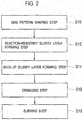
- Fig. 2 is a flowchart showing the method of manufacturing the casting mold 10 to cast a TiAl alloy.
- the method of manufacturing the casting mold 10 to cast a TiAl alloy includes a wax pattern shaping step (S10), a reaction-resistant slurry layer forming step (S12), a back-up slurry layer forming step (S14), a dewaxing step (S16), and a burning step (S18).
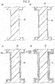
- Fig. 3 includes cross-sectional views for explaining the respective steps in the method of manufacturing the casting mold 10 to cast a TiAl alloy, in which Fig. 3 (a) is a cross-sectional view for explaining the wax pattern shaping step (S10), Fig. 3(b) is a cross-sectional view for explaining the reaction-resistant slurry layer forming step (S12), and Fig. 3(c) and Fig. 3(d) are cross-sectional views for explaining the back-up slurry layer forming step (S14).
- Fig. 3 (a) is a cross-sectional view for explaining the wax pattern shaping step (S10)
- Fig. 3(b) is a cross-sectional view for explaining the reaction-resistant slurry layer forming step (S12)
- Fig. 3(c) and Fig. 3(d) are cross-sectional views for explaining the back-up slurry layer forming step (S14).
- the wax pattern shaping step (S10) is a step of shaping a wax pattern model 22 for forming the casting mold body 14 that is formed into a bottomed shape and provided with the cavity 12 into which the molten TiAl alloy is to be poured.
- the wax pattern model 22 for forming the casting mold body 14 is shaped by using a wax material.
- the wax pattern model 22 is shaped by pouring the wax material into a mold by injection molding and the like, then curing the wax material, and taking the wax material out of the mold.
- the reaction-resistant slurry layer forming step (S12) is a step of forming a reaction-resistant slurry layer 24 by coating the wax pattern model 22 with reaction-resistant slurry formed by mixing refractory particles including at least one of cerium oxide, yttrium oxide, and zirconium oxide, with binder and performing stucco processing with a reaction-resistant stucco material formed from refractory particles including at least one of cerium oxide, yttrium oxide, and zirconium oxide.
- the reaction-resistant slurry is coated on the wax pattern model 22.
- the reaction-resistant slurry includes the refractory particles having low reactivity with the molten TiAl alloy, and the binder.
- Refractory particles including at least one of cerium oxide, yttrium oxide, and zirconium oxide are used as the refractory particles of the reaction-resistant slurry.
- the refractory particles of the reaction-resistant slurry may use one of these oxides alone or use a combination of these oxides. Meanwhile, refractory particles of #325 mesh size, for example, can be used as the refractory particles of the reaction-resistant slurry.
- silica sol such as colloidal silica, zirconia sol, yttria sol, and organic binder such as phenol resin
- the binder may use one of these materials alone or use a combination of these materials.
- silica sol is used as the binder, cerium oxide as the refractory particles in order to suppress a reaction between the molten TiAl alloy and silica sol may be used.
- a dipping method, a spraying method, and an applying method can be used as a method of coating the reaction-resistant slurry. Nonetheless, the dipping method may be used because this method can achieve uniform coating on the wax pattern model 22.
- the wax pattern model 22 coated with the reaction-resistant slurry is subjected to stucco processing with the reaction-resistant stucco material and is then dried.
- Refractory particles including at least one of cerium oxide, yttrium oxide, and zirconium oxide in a range from #60 mesh size to #160 mesh size, for example, are used as the reaction-resistant stucco material.
- the wax pattern model 22 is subjected to the coating of the reaction-resistant slurry and the stucco processing with the reaction-resistant stucco material, and the reaction-resistant slurry layer 24 is thus formed on the wax pattern model 22.
- the coating of the reaction-resistant slurry and the stucco processing with the reaction-resistant stucco material may be repeated several times in order to form the reaction-resistant slurry layer 24 into a prescribed thickness.
- the back-up slurry layer forming step (S14) is a step of forming a back-up slurry layer 26 on the reaction-resistant slurry layer 24.
- the back-up slurry layer 26 including a weakening slurry layer 26a and a shape-retention slurry layer 26b is formed on the reaction-resistant slurry layer 24.
- weakening slurry is coated on the reaction-resistant slurry layer 24.
- the weakening slurry is formed by mixing refractory particles, which contain fused silica in a range from 80% by mass to 100% by mass inclusive, with binder.
- the refractory particles constituting the weakening slurry may include fused silica in a range from 90% by mass to 100% by mass inclusive.
- the refractory particles constituting the weakening slurry may consist of fused silica (100% by mass of fused silica).
- At least one of oxides including zirconium silicate (ZrSiO 4 ), aluminum oxide (Al 2 O 3 ), zirconium oxide (ZrO 2 ), magnesium oxide (MgO), mullite (Al 6 Si 2 O 13 ), and the like can be used in the rest of the refractory particles constituting the weakening slurry.
- refractory particles of #325 mesh size for example, can be used as the refractory particles of the weakening slurry.
- the binder such as silica sol as in the reaction-resistant slurry can be used.
- silica sol such as colloidal silica may be used.
- a surface coated with the weakening slurry is subjected to stucco processing with a weakening stucco material, and then the processed surface is dried.
- Refractory particles containing fused silica in a range from 80% by mass to 100% by mass inclusive are used in the weakening stucco material.
- Refractory particles containing fused silica in a range from 90% by mass to 100% by mass inclusive may be used in the weakening stucco material.
- the refractory particles constituting the weakening stucco material may consist of fused silica (100% by mass of fused silica).
- Refractory particles such as zirconium silicate (ZrSiO 4 ), aluminum oxide (Al 2 O 3 ), zirconium oxide (ZrO 2 ), magnesium oxide (MgO), and mullite (Al 6 Si 2 O 13 ) can be used in the rest of the refractory particles constituting the weakening stucco material.
- refractory particles in a range from #60 mesh size to #160 mesh size, for example, can be used as the refractory particles of the weakening stucco material.
- the coating of the weakening slurry and the stucco processing with the weakening stucco material may be repeated twice to five times, for example, until the weakening slurry layer 26a reaches a prescribed thickness.
- shape-retention slurry is coated on the weakening slurry layer 26a.
- the shape-retention slurry is formed by mixing refractory particles with binder.
- At least one of oxides including zirconium silicate (ZrSiO 4 ), silicon dioxide (SiO 2 ), aluminum oxide (Al 2 O 3 ), mullite (Al 6 Si 2 O 13 ), and the like can be used as the refractory particles of the shape-retention slurry.
- Binder such as silica sol as in the reaction-resistant slurry can be used as the binder.
- refractory particles of #325 mesh size for example, can be used as the refractory particles of the shape-retention slurry.
- a surface coated with the shape-retention slurry is subjected to stucco processing with a shape-retention stucco material, and then the processed surface is dried.
- Refractory particles of at least one of oxides including zirconium silicate (ZrSiO 4 ), silicon dioxide (SiO 2 ), aluminum oxide (Al 2 O 3 ), mullite (Al 6 Si 2 O 13 ), and the like can be used as the shape-retention stucco material.
- refractory particles in a range from #60 mesh size to #160 mesh size, for example, can be used as the refractory particles of the shape-retention stucco material.
- the coating of the shape-retention slurry and the stucco processing with the shape-retention stucco material may be repeated twice to five times, for example, until the shape-retention slurry layer 26b reaches a prescribed thickness.
- the back-up slurry layer 26 including the weakening slurry layer 26a and the shape-retention slurry layer 26b is formed on the reaction-resistant slurry layer 24.
- the weakening slurry layer 26a may be formed directly on the reaction-resistant slurry layer 24 and then the shape-retention slurry layer 26b may be formed on the weakening slurry layer 26a, or the shape-retention slurry layer 26b may be formed directly on the reaction-resistant slurry layer 24 and then the weakening slurry layer 26a may be formed on the shape-retention slurry layer 26b.
- the back-up slurry layer 26 may be constructed by alternately forming the weakening slurry layers 26a and the shape-retention slurry layers 26b.
- the weakening slurry layer 26a may be formed directly on the reaction-resistant slurry layer 24 in order to form the weakening layer 18a directly on the reaction-resistant layer 16.
- the dewaxing step (S18) is a step of shaping a casting mold compact by heating and dewaxing the wax pattern model 22 provided with the reaction-resistant slurry layer 24 and the back-up slurry layer 26.
- the casting mold compact is shaped by melting and thus removing the wax pattern model 22.
- the dewaxing is conducted by putting the wax pattern model 22 provided with the reaction-resistant slurry layer 24 and the back-up slurry layer 26 into an autoclave or the like, and subjecting the wax pattern model 22 to a heat and pressure treatment at a temperature in a range from 100°C to 180°C and a pressure in a range from 4 atm (0.4 MPa) to 8 atm (0.8 MPa).
- the wax pattern model 22 is eluted and the casting mold compact (a green compact) is obtained.
- the burning step (S16) is a step of heating and burning the casting mold compact at a burning temperature in a range from 1000°C to 1100°C inclusive.
- the reaction-resistant slurry layer 24 is sintered into the reaction-resistant layer 16
- the back-up slurry layer 26 including the weakening slurry layer 26a and the shape-retention slurry layer 26b is sintered into the back-up layer 18 including the weakening layer 18a and the shape-retention layer 18b.
- the casting mold compact becomes a shell that forms the casting mold 10.
- the cavity 12 is formed at a position from which the wax pattern model 22 is eluted.
- a burning period is set in a range from one hour to ten hours, for example.
- cristobalite produced from fused silica contained in the weakening slurry layer 26a has the phase transformation from the ⁇ -type ( ⁇ -cristobalite) to the ⁇ -type ( ⁇ -cristobalite), which brings about the change in volume and causes the cracks (the microcracks) in the weakening layer 18a.
- the strength of the weakening layer 18a can be reduced.
- the cooling after the heating may take the form of furnace cooling or air cooling. However, the air cooling brings about more cracks (the microcracks) in the weakening layer 18a.
- the rate of the amount of cristobalite in the silica material formed from fused silica and cristobalite falls in the range from 26% by mass to the 34% by mass inclusive.
- the burning temperature is equal to or above 1000°C. Specifically, if the burning temperature is below 1000°C, the rate of the amount of cristobalite in the silica material contained in the weakening layer 18a falls below 26% by mass, whereby the cracks (the microcracks) occurring in the weakening layer 18a are reduced and the casting mold strength is increased.
- the burning temperature is equal to or below 1100°C. Specifically, if the burning temperature is equal to 1100°C, then the rate of the amount of cristobalite in the silica material contained in the weakening layer 18a is equal to 34% by mass, whereby the cracks (the microcracks) can be sufficiently brought about in the weakening layer 18a and the casting mold strength can be reduced. Another reason is that production efficiency drops if the burning temperature is higher than 1100°C. Here, the burning temperature may be equal to 1100°C.
- the TiAl alloy put into a melting crucible in a melting chamber of a melting furnace is melted in vacuum, and the molten TiAl alloy is held at a prescribed temperature.
- the casting mold 10 preheated to a prescribed temperature is put into a casting mold chamber of the melting furnace and is evacuated.
- the casting mold temperature may be in a range from 1100°C to 1300°C. If the casting mold temperature is below 1100°C, a casting defect is likely to occur due to misrun and the like. If the casting mold temperature is higher than 1300°C, crystal grain coarsening is likely to occur.
- a casting temperature may be set in a range from 30°C above to 160°C above the melting point of the TiAl alloy.
- the casting temperature is lower than the temperature that is 30°C above the melting point of the TiAl alloy, a casting defect is likely to occur due to misrun and the like.
- the casting temperature is higher than the temperature that is 160°C above the melting point of the TiAl alloy, the heating may be difficult due to restrictions of a casting facility and the like, or crystal grain coarsening is likely to occur.
- the casting mold 10 into which the molten TiAl alloy is poured is moved to the casting mold chamber and then the gate valve is closed.
- the casting mold 10 moved to the casting mold chamber is let stand for a predetermined time period in vacuum. Having let the casting mold 10 stand, the casting mold chamber is opened to the atmosphere. Then, the casting mold 10 in which the TiAl alloy is cast is taken out.
- the casting mold 10 is loaded on a wagon and is let stand until the casting mold 10 is cooled down to a room temperature.
- Fig. 4 is a diagram showing a configuration of a turbine blade 30 which is the TiAl alloy cast product.
- the turbine blade 30 is formed from a blade body 32, a shroud 34, and a platform 36.
- a length in its longitudinal direction is from 200 mm to 300 mm
- a length in its width direction is from 50 mm to 70 mm
- its thickness is from 3 mm to 7 mm, for example.
- the turbine blade 30 is restrained by the casting mold in a cooling process (from 1100°C to 1000°C) after the casting, and a tensile stress is applied to the turbine blade 30 in the longitudinal direction thereof. Accordingly, in the case of using a conventional casting mold, fractures or cracks are likely to occur in a region A between the blade body 32 and the shroud 34 or in a region B between the blade body 32 and the platform 36.
- an amount of shrinkage of the turbine blade 30 becomes larger than an amount of shrinkage of the casting mold 10, and a compressive stress is applied to the casting mold 10 at the time of shrinkage of the turbine blade 30, whereby cracks occur from the weakening layer 18a of the casting mold 10.
- the turbine blade 30 is released from the restraint of the casting mold 10, and fractures or cracks in the turbine blade 30 can be suppressed.
- the casting mold since the casting mold includes the weakening layer with the reduced casting mold strength, cracks occur from the weakening layer of the casting mold in the cooling process (from 1100°C to 1000°C) after casting the molten TiAl alloy.
- the TiAl alloy cast product is released from the restraint of the casting mold, and fractures or cracks in the TiAl alloy cast product are suppressed.
- Turbine blades made of a TiAl alloy were cast and occurrence of cracks therein was evaluated. First, high-temperature strength characteristics of molds were evaluated.
- each of the casting molds was provided with the two-layered reaction-resistant slurry layer by repeating the coating of the reaction-resistant slurry and the stucco processing with the reaction-resistant stucco material twice on the wax pattern model.
- Slurry formed by mixing cerium oxide particles with colloidal silica was used as the reaction-resistant slurry.
- Cerium oxide particles were used as the reaction-resistant stucco material.
- the cerium oxide particles of #325 mesh size were used in the reaction-resistant slurry while the cerium oxide particles of #100 mesh size were used in the reaction resistant stucco material.
- the weakening slurry layer was formed on the reaction-resistant slurry by performing the coating of the weakening slurry and the stucco processing with the weakening stucco material thereon.
- the weakening slurry formed by mixing the refractory particles consisting of fused silica particles (100% by mass of the fused silica particles) with colloidal silica was used in the casting mold of Example 1.
- the weakening slurry formed by mixing the refractory particles containing 90% by mass of the fused silica particles and 10% by mass of zirconium silicate particles with colloidal silica was used in the casting mold of Example 2.
- the weakening slurry formed by mixing the refractory particles containing 80% by mass of the fused silica particles and 20% by mass of the zirconium silicate particles with colloidal silica was used in the casting mold of Example 3.
- the same weakening slurry as that for the casting mold of Example 1 was used in the casting molds of Examples 4 to 6.
- the refractory particles of #325 mesh size were used in the weakening slurry.
- the weakening stucco material containing 90% by mass of the fused silica particles and 10% by mass of the zirconium silicate particles was used in the casting mold of Example 2.
- the weakening stucco material containing 80% by mass of the fused silica particles and 20% by mass of the zirconium silicate particles was used in the casting mold of Example 3.
- the same weakening stucco material as that for the casting mold of Example 1 was used in the casting molds of Examples 4 to 6.
- the refractory particles of #100 mesh size were used in each weakening stucco material.
- the two-layered weakening slurry layer was formed on the reaction-resistant slurry layer by repeating the coating of the weakening slurry and the stucco processing with the weakening stucco material twice.
- the single-layered weakening slurry layer was formed on the reaction-resistant slurry layer by performing the coating of the weakening slurry and the stucco processing with the weakening stucco material once.
- the three-layered weakening slurry layer was formed on the reaction-resistant slurry layer by repeating the coating of the weakening slurry and the stucco processing with the weakening stucco material three times.
- the five-layered weakening slurry layer was formed on the reaction-resistant slurry layer by repeating the coating of the weakening slurry and the stucco processing with the weakening stucco material five times.
- the shape-retention slurry layer was formed on the weakening slurry layer by performing the coating of the shape-retention slurry and the stucco processing with the shape-retention stucco material.
- Mullite particles were used in the shape retention stucco material.
- the casting molds of Examples 1 to 6 used the same shape-retention slurry and the same shape-retention stucco material.
- the refractory particles of #325 mesh size were used in the shape-retention slurry while the refractory particles of #100 mesh size were used in the shape-retention stucco material.
- the three-layered shape-retention slurry layer was formed on the weakening slurry layer by repeating the coating of the shape-retention slurry and the stucco processing with the shape-retention stucco material twice and then lastly performing the coating of the shape-retention slurry.
- the four-layered shape-retention slurry layer was formed on the weakening slurry layer by repeating the coating of the shape-retention slurry and the stucco processing with the shape-retention stucco material three times and then lastly performing the coating of the shape-retention slurry.
- the two-layered shape-retention slurry layer was formed on the weakening slurry layer by performing the coating of the shape-retention slurry and the stucco processing with the shape-retention stucco material once and then lastly performing the coating of the shape-retention slurry.
- the single-layered shape-retention slurry layer was formed on the weakening slurry layer by performing the coating of the shape-retention slurry.
- the back-up slurry layer including the weakening slurry layer and the shape-retention slurry layer was formed on each reaction-resistant slurry layer.
- each wax pattern model provided with the reaction-resistant slurry layer and the back-up slurry layer was heated to 180°C and dewaxed by using the autoclave, and was thereby formed into the casting mold compact (the green compact).
- the casting mold compact was burned in the burning furnace at 1100°C for three to five hours, whereby the reaction-resistant slurry layer and the back-up slurry layer were sintered into the shell.
- the casting molds of Examples 1 to 6 were formed.
- the same conditions of the dewaxing process and the same burning conditions were applied to the casting molds of Examples 1 to 6.
- the weakening slurry and the weakening stucco material are different from those of the casting molds of Examples 1 to 3.
- slurry formed by mixing refractory particles containing 70% by mass of the fused silica particles and 30% by mass of the zirconium silicate particles with colloidal silica was used in the casting mold of Comparative Example 1.
- a stucco material formed by mixing 70% by mass of the fused silica particles with 30% by mass of the zirconium silicate particles was used in the casting mold of Comparative Example 1.
- the casting mold of Comparative Example 2 is different from the casting molds of Examples 1 to 6 in that the weakening slurry layer is not formed therein.
- slurry formed by mixing refractory particles containing 30% by mass of the fused silica particles and 70% by mass of the zirconium silicate particles with colloidal silica was coated on the reaction-resistant slurry layer, and then the stucco processing was performed thereon by using a stucco material made of the mullite particles.
- the five-layered slurry layer was formed by repeating the coating of this slurry and the stucco processing with this stucco material four times and then lastly performing the coating of this slurry.
- the burning temperature after the dewaxing process was set to 1050°C.
- Other features are the same as those of the methods of manufacturing the casting molds of Examples 1 to 6 and detailed description thereof will be omitted.
- the fused silica particles and the zirconium silicate particles of #325 mesh size were used for the slurry while those of #100 mesh size were used in the stucco material.
- the casting mold of Comparative Example 2 is the same casting mold as the conventional casting mold to cast a titanium alloy.
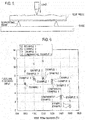
- Fig. 5 is a diagram showing a method of testing strength of the casting mold. The strength test was carried out in accordance with the ICI (Investment Casting Institute) Ceramics Testing Guidebook, and flexural strength (MPa) was measured therein. A span between supporting points was set to 40 mm, and a point angle of each supporting point was set to 2R. The strength test was carried out by applying a load to the test piece while heating and holding the test piece at a test temperature.
- the high-temperature strength characteristics of the casting molds of Examples 1 to 3 and Comparative Examples 1 and 2 will be described.
- the casting molds of Examples 1 to 3 and Comparative Example 1 were tested in a range from 1000°C to 1500°C while the casting mold of Comparative Example 2 was tested in a range from a room temperature to 1400°C.
- Fig. 6 is a graph showing the high-temperature strength characteristics of the casting molds of Examples 1 to 3 and Comparative Example 1.
- the horizontal axis indicates the test temperature and the vertical axis indicates the flexural strength.
- the flexural strength of the casting mold of Example 1 is indicated with white circles.
- the flexural strength of the casting mold of Example 2 is indicated with white squares.
- the flexural strength of the casting mold of Example 3 is indicated with white rhombuses.
- the flexural strength of the casting mold of Comparative Example 1 is indicated with x.
- the high-temperature strength of the casting mold of each of Examples 1 to 3 fell below the high-temperature strength of the casting mold of Comparative Example 1. Moreover, in the temperature range from 1000°C to 1100°C, the high-temperature strength of the casting mold of each of Examples 1 and 2 fell even below the high-temperature strength of the casting mold of Example 3.
- Fig. 7 is a graph showing the high-temperature strength characteristics of the casting mold of Comparative Example 2.
- the horizontal axis indicates the test temperature and the vertical axis indicates the flexural strength.
- the flexural strength at each test temperature is indicated with a white circle.
- the high-temperature strength of the casting mold of Comparative Example 2 was higher than the high-temperature strength of the casting mold of each of Examples 1 to 3 in the temperature range from 1000°C to 1100°C.
- the casting mold strength of the conventional casting mold to cast a titanium alloy was increased in a cooling process (from 1100°C to 1000°C) after casting a TiAl alloy cast product, and the casting mold was less likely to cause cracks.
- the test temperature was set in a range from a room temperature to 1300°C.
- Fig. 8 is a graph showing the high-temperature strength characteristics of the casting molds of Examples 1, 4, 5, and 6.
- the horizontal axis indicates the test temperature and the vertical axis indicates the flexural strength.
- the flexural strength of the casting mold of Example 1 is indicated with white circles.
- the flexural strength of the casting mold of Example 4 is indicated with black circles.
- the flexural strength of the casting mold of Example 5 is indicated with black squares.
- the flexural strength of the casting mold of Example 6 is indicated with white squares.
- Example 6 had the lowest strength and the casting mold of Example 4 had the highest strength at any test temperature, and that a relation of Example 6 ⁇ Example 5 ⁇ Example 1 ⁇ Example 4 was applicable. This made it clear that the thinner weakening layer had the higher high-temperature strength and the thicker weakening layer had the lower high-temperature strength.
- Fig. 9 includes photographs showing a result of cross-sectional structure observation of the casting molds of Example 2 and Comparative Example 1.
- Fig. 9(a) is a photograph showing a result of cross-sectional structure observation of the casting mold of Comparative Example 1
- Fig. 9(b) is a photograph showing a result of cross-sectional structure observation of the casting mold of Example 2.
- a region of the casting mold subjected to the cross-sectional structure observation is the weakening layer.
- a region of the casting mold subjected to the cross-sectional structure observation is the layer formed from the refractory particles containing 70% by mass of the fused silica particles and 30% by mass of the zirconium silicate particles, which corresponds to the weakening layer of the casting mold of Example 2.
- the high-temperature strength characteristics of the green compact for the casting mold of Example 1 at the point after the dewaxing process and before the burning process were evaluated in order to evaluate an influence of the burning process after the dewaxing process.
- a test piece was formed by cutting it out of the green compact. The size of the test piece and the method of the strength test were arranged in accordance with the aforementioned ICI (Investment Casting Institute) Ceramics Testing Guidebook.
- Fig. 10 is a graph showing the high-temperature strength characteristics of the green compact.
- the horizontal axis indicates the test temperature and the vertical axis indicates the flexural strength.
- the flexural strength at each test temperature is indicated with a black circle.
- Silica casting molds made of fused silica were formed in order to evaluate a relation between the burning temperature and the amount of cristobalite in connection with the reduction in strength of the casting mold. First, a method of forming the silica casting molds will be described.
- Silica slurry formed by mixing fused silica particles with colloidal silica was coated on each wax pattern model, and then stucco processing was performed with a silica stucco material formed from fused silica particles.
- silica slurry and the silica stucco material the same materials as those of the weakening slurry and the weakening stucco material of the casting mold of Example 1 were used, respectively.
- a seven-layered silica slurry layer was formed by repeating the coating of the silica slurry and the stucco processing with the silica stucco material six times and then lastly performing the coating of the silica slurry.
- the wax pattern models each provided with the silica slurry layer were subjected to the dewaxing process by heating the wax pattern models at 180°C with an autoclave. After the dewaxing process, the wax pattern models were burned in a burning furnace at temperatures of 800°C, 900°C, 940°C, 970°C, 1000°C, 1050°C, and 1100°, respectively.
- the silica casting molds were formed by sintering the silica slurry layers into shells.
- test pieces were formed by cutting them out of the silica casting molds, respectively.
- the size of each test piece and the method of the strength test were arranged in accordance with the aforementioned ICI (Investment Casting Institute) Ceramics Testing Guidebook.
- the strength tests were conducted at a room temperature.
- the silica casting molds burned at the various burning temperatures were subjected to quantification of the amount of cristobalite by measuring the rates of the amount of cristobalite in accordance with an X-ray diffraction method.
- the rate of the amount of cristobalite is a proportion of cristobalite with respect to a sum of fused silica and cristobalite.
- a horizontal sample mounting multipurpose X-ray diffraction system Ultima-IV manufactured by Rigaku Corporation was used as an X-ray diffraction system.
- the quantification of cristobalite was conducted in accordance with an internal standard method using silicon as a standard sample, and calibration curves for strengths of quartz and cristobalite formed in advance were used for calculation.
- the X-ray diffraction measurement was conducted by using a X-ray tube with a Cu target and under the following conditions, namely, an acceleration voltage at 40 kV, a current at 40 mA, a scan speed at 1 degree per minute, a measurement angle of cristobalite in a range from 21.0 degrees to 22.3 degrees, and a measurement angle of silicon in a range from 27.9 degrees to 29.0 degrees.
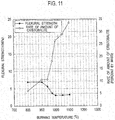
- Fig. 11 is a graph showing a relation between room-temperature strength of the silica casting mold and the rate of the amount of cristobalite.
- the horizontal axis indicates the burning temperature
- the left vertical axis indicates the flexural strength
- the right vertical axis indicates the rate of the amount of cristobalite.
- the flexural strength is indicated with black circles while the rates of the amount of cristobalite are indicated with white circles.
- the strength of the silica casting mold started declining at the burning temperature of 900°C, and reached the lowest at the burning temperature in the range from 1000°C to equal to or below 1100°C.
- the rates of the amount of cristobalite in the silica casting mold were equal to 11% by mass at the burning temperature of 900°C, 26% by mass at the burning temperature of 1000°C, and 34% by mass at the burning temperature of 1100°C, respectively.
- a turbine blade made of a TiAl alloy was cast by using the casting mold of Example 1, and a crack occurrence rate of the turbine blade was evaluated.
- the casting mold of Example 1 and the casting mold of Comparative Example 2 were used as the casting molds to cast the turbine blade.
- a TiAl alloy having the composition of Ti-48at% Al-2at% Nb-2at% Cr was used as the TiAl alloy.
- As for the size of the turbine blade a length in its longitudinal direction was set to about 250 mm, a length in its width direction was set to about 60 mm, and its thickness was set to about 6 mm.
- the TiAl alloy put into the melting crucible in the melting chamber of the melting furnace was melted in vacuum, and the molten TiAl alloy was held at a prescribed temperature.
- the casting molds preheated to the temperature in the range from 1100°C to 1300°C were put into the casting mold chamber of the melting furnace and were evacuated.
- the gate valve between the casting mold chamber and the melting chamber was opened and the casting molds were moved into the melting chamber.
- the molten TiAl alloy was poured into the casting molds while tilting the melting crucible. Meanwhile, the casting temperature was set in the range from 30°C above to 160°C above the melting point of the TiAl alloy.
- the casting molds into which the molten TiAl alloy was poured were moved to the casting mold chamber.
- the casting molds moved to the casting mold chamber were let stand for about 20 minutes in vacuum. Having let the casting molds stand, the casting mold chamber was opened to the atmosphere. Then, the casting molds in which the TiAl alloy was cast were taken out.
- the casting molds were loaded on the wagon and were let stand until the casting molds were cooled down to a room temperature. In the meantime, surface temperatures of the casting molds were measured with an infrared camera.
- the present invention can suppress fractures or cracks in TiAl alloy cast products, and are therefore useful for casting TiAl alloy cast products such as turbine blades.
Landscapes
- Engineering & Computer Science (AREA)
- Mechanical Engineering (AREA)
- Chemical & Material Sciences (AREA)
- Materials Engineering (AREA)
- Metallurgy (AREA)
- Organic Chemistry (AREA)
- Mold Materials And Core Materials (AREA)
- Molds, Cores, And Manufacturing Methods Thereof (AREA)
Abstract
Description
- The present invention relates to a casting mold, a method of manufacturing the same, a TiAl alloy cast product, and a method of casting the same. More specifically, the present invention relates to a casting mold to cast a TiAl (titanium aluminide) alloy, a method of manufacturing the same, a TiAl alloy cast product, and a method of casting the same.
- A TiAl alloy which is an intermetallic compound of titanium and aluminum has excellent properties such as specific strength in a high-temperature range, and is therefore applied to products such as a turbine blade of a jet engine. A casting mold used for casting the turbine blade or the like made of the TiAl alloy is the same as a casting mold to cast a titanium alloy.
-
PTL 1 describes a casting mold for a titanium alloy in which at least a first layer of a cavity surface of a casting mold body constituting the casting mold is formed from a burned product of slurry that includes an aggregate mainly composed of cerium oxide and binder mainly composed of at least zirconia sol. - [PTL 1] Japanese Patent Application Publication No.
2007-69246 - Meanwhile, a TiAl alloy is an intermetallic compound and is therefore a brittle material. Accordingly, a TiAl alloy cast product may cause fractures or cracks due to its shrinkage in a cooling process (from 1100°C to 1000°C) after the casting. To be more precise, at the time of cooling after the casting, the casting mold restrains the TiAl alloy cast product and applies a tensile stress to the TiAl alloy cast product because an amount of shrinkage of the TiAl alloy cast product becomes larger than an amount of shrinkage of the casting mold due to a difference in thermal expansion between the TiAl alloy cast product and the casting mold. As a consequence, the TiAl alloy cast product is likely to cause fractures or cracks.
- Accordingly, an object of the present invention is to provide a casting mold, a method of manufacturing the same, a TiAl alloy cast product, and a method of casting the same, which are capable of suppressing fractures or cracks in a TiAl alloy cast product.
- A casting mold according to the invention is a casting mold to cast a TiAl alloy, including a casting mold body formed into a bottomed shape and provided with a cavity into which a molten TiAl alloy is to be poured, wherein the casting mold body includes a reaction-resistant layer provided on the cavity side, formed from a refractory material containing at least one of cerium oxide, yttrium oxide, and zirconium oxide, and configured to suppress a reaction with the molten TiAl alloy, and a back-up layer formed on the reaction-resistant layer, and the back-up layer includes a weakening layer formed from a refractory material including a silica material in a range from 80% by mass to 100% by mass inclusive, the silica material containing cristobalite in a range from 26% by mass to 34% by mass inclusive and the rest being fused silica, the weakening layer being designed to reduce casting mold strength, and a shape-retention layer formed from a refractory material and designed to retain a casting mold shape.
- The casting mold according to the invention, wherein the refractory material forming the weakening layer includes the silica material in a range from 90% by mass to 100% by mass inclusive.
- The casting mold according to the invention, wherein the refractory material forming the weakening layer consists of the silica material.
- The casting mold according to the invention, wherein the weakening layer is formed directly on the reaction-resistant layer.
- A method of manufacturing a casting mold according to the invention is a method of manufacturing a casting mold to cast a TiAl alloy, including a wax pattern shaping step of shaping a wax pattern model for forming a casting mold body, the casting mold body being formed into a bottomed shape and provided with a cavity into which a molten TiAl alloy is to be poured, a reaction-resistant slurry layer forming step of forming a reaction-resistant slurry layer by coating the wax pattern model with reaction-resistant slurry formed by mixing refractory particles including at least one of cerium oxide, yttrium oxide, and zirconium oxide, with binder, and performing stucco processing with a reaction-resistant stucco material formed from refractory particles including at least one of cerium oxide, yttrium oxide, and zirconium oxide, a back-up slurry layer forming step of forming a back-up slurry layer on the reaction-resistant slurry layer, a dewaxing step of shaping a casting mold compact by heating and dewaxing the wax pattern model provided with the reaction-resistant slurry layer and the back-up slurry layer and a burning step of heating and burning the casting mold compact at a temperature in a range from 1000°C to 1100°C inclusive, wherein the back-up slurry layer is formed in the back-up slurry layer forming step by forming a weakening slurry layer by coating weakening slurry, which is formed by mixing refractory particles including fused silica in a range from 80% by mass to 100% by mass inclusive, with binder, and performing stucco processing with a weakening stucco material formed from refractory particles including fused silica in a range from 80% by mass to 100% by mass inclusive, and forming a shape-retention slurry layer by providing shape-retention slurry, which is formed by mixing refractory particles with binder, and performing stucco processing with a shape-retention stucco material formed from refractory particles.
- The method of manufacturing a casting mold according to the invention, wherein the weakening slurry layer is formed in the back-up slurry layer forming step by coating the weakening slurry, which is formed by mixing the refractory particles including fused silica in a range from 90% by mass to 100% by mass inclusive, with the binder, and performing the stucco processing with the weakening stucco material formed from the refractory particles including fused silica in a range from 90% by mass to 100% by mass inclusive.
- The method of manufacturing a casting mold according to the invention, wherein the weakening slurry layer is formed in the back-up slurry layer forming step by coating the weakening slurry, which is formed by mixing the refractory particles consisting of fused silica, with the binder, and performing the stucco processing with the weakening stucco material formed from the refractory particles consisting of fused silica.
- The method of manufacturing a casting mold according to the invention, wherein the weakening slurry layer is formed directly on the reaction-resistant slurry layer in the back-up slurry layer forming step.
- A TiAl alloy cast product cast with the casting mold according to the invention.
- A method of casting a TiAl alloy cast product according to the invention including the steps of heating the casting mold according to the invention to a range from 1100°C to 1300°C and performing casting by pouring a molten TiAl alloy into the casting mold.
- According to the above-described configurations, since the casting mold to cast a TiAl alloy is provided with the weakening layer to reduce the casting mold strength, cracks on the casting mold occur in the weakening layer in a cooling process (from 1100°C to 1000°C) after the casting. As a consequence, a TiAl alloy cast product is released from restraint of the casting mold, and fractures or cracks in the TiAl alloy cast product can thus be suppressed.
-
- [
Fig. 1 ]
Fig. 1 is a cross-sectional view showing a configuration of a casting mold to cast a TiAl alloy in an embodiment of the present invention. - [
Fig. 2 ]
Fig. 2 is a flowchart showing a method of manufacturing the casting mold to cast a TiAl alloy in the embodiment of the present invention. - [
Fig. 3 ]
Fig. 3 includes cross-sectional views for explaining respective steps in the method of manufacturing the casting mold to cast a TiAl alloy in the embodiment of the present invention. - [
Fig. 4 ]
Fig. 4 is a diagram showing a configuration of a turbine blade which is a TiAl alloy cast product in the embodiment of the present invention. - [
Fig. 5 ]
Fig. 5 is a diagram showing a method of testing strength of a casting mold in the embodiment of the present invention. - [
Fig. 6 ]
Fig. 6 is a graph showing high-temperature strength characteristics of casting molds of Examples 1 to 3 and Comparative Example 1 in the embodiment of the present invention. - [
Fig. 7 ]
Fig. 7 is a graph showing high-temperature strength characteristics of a casting mold of Comparative Example 2 in the embodiment of the present invention. - [
Fig. 8 ]
Fig. 8 is a graph showing high-temperature strength characteristics of casting molds of Examples 1, 4, 5, and 6 in the embodiment of the present invention. - [
Fig. 9 ]
Fig. 9 includes photographs showing a result of cross-sectional structure observation of the casting molds of Example 2 and Comparative Example 1 in the embodiment of the present invention. - [
Fig. 10 ]
Fig. 10 is a graph showing high-temperature strength characteristics of a green compact in the embodiment of the present invention. - [
Fig. 11 ]
Fig. 11 is a graph showing a relation between room-temperature strength of a silica casting mold and a rate of an amount of cristobalite in the embodiment of the present invention. - An embodiment of the present invention will be described below in detail with reference to the drawings.
Fig. 1 is a cross-sectional view showing a configuration of acasting mold 10 to cast a TiAl alloy. Thecasting mold 10 shown inFig. 1 is a casting mold to cast a turbine blade as a TiAl alloy cast product. - The
casting mold 10 includes acasting mold body 14 formed into a bottomed shape and provided with acavity 12 into which a molten TiAl alloy is to be poured. Thecasting mold body 14 includes a bladebody casting portion 14a to cast a blade body, ashroud casting portion 14b to cast a shroud, and aplatform casting portion 14c to cast a platform. Thecasting mold body 14 is provided with a sprue (not shown) used for pouring the molten TiAl alloy into theempty cavity 12. - The
casting mold body 14 includes a reaction-resistant layer 16, which is provided on the cavity side and designed to suppress a reaction with the molten TiAl alloy. The reaction-resistant layer 16 is formed from a refractory material, which is made of an oxide and the like having low reactivity with the molten TiAl alloy. The refractory material for the reaction-resistant layer 16 contains at least one of cerium oxide (CeO2), yttrium oxide (Y2O3), and zirconium oxide (ZrO2). The refractory material for the reaction-resistant layer 16 may use one of these oxides alone or use a combination of these oxides. A thickness of the reaction-resistant layer 16 is in a range from 0.5 mm to 2.0 mm, for example. - Cerium oxide which has lower reactivity with the molten TiAl alloy than that of zirconium oxide and is also inexpensive may be used as a main component of the refractory material for the reaction-
resistant layer 16. By using cerium oxide, it is possible to inhibit the TiAl alloy cast product from burning to thecasting mold 10 and thus to improve surface smoothness of the TiAl alloy cast product. - The casting
mold body 14 includes a back-uplayer 18 which is made of a refractory material and is formed on the reaction-resistant layer 16. The back-uplayer 18 is formed from aweakening layer 18a to reduce casting mold strength, and a shape-retention layer 18b to retain a casting mold shape. - The
weakening layer 18a is formed from a refractory material which includes a silica material in a range from 80% by mass to 100% by mass inclusive. Here, the silica material contains cristobalite in a range from 26% by mass to 34% by mass inclusive, and the rest is fused silica. A thickness of theweakening layer 18a is in a range from 0.5 mm to 2.0 mm, for example. - The silica material included in the refractory material that forms the
weakening layer 18a contains cristobalite. Cristobalite has a phase transformation between β-type (β-cristobalite) and α-type (α-cristobalite) in a temperature range from 200°C to 300°C. This phase transformation brings about a change in volume and causes cracks (microcracks) in theweakening layer 18a. Thus, the casting mold strength can be reduced. - A rate of the amount of cristobalite in the silica material is in the range from 26% by mass to the 34% by mass inclusive, or may be equal to 34% by mass due to the following reason. Specifically, if the rate of the amount of cristobalite in the silica material is below 26% by mass, the cracks (the microcracks) in the
weakening layer 18a are reduced and high-temperature strength of the castingmold 10 in a cooling process (from 1100°C to 1000°C) after the casting is increased as a consequence. On the other hand, when the rate of the amount of cristobalite in the silica material is equal to 34% by mass, the cracks (the microcracks) in theweakening layer 18a are increased to reach a sufficient amount for reducing the strength of the castingmold 10 in the cooling process (from 1100°C to 1000°C) after the casting. - A reason why the content rate of the silica material included in the refractory material is set equal to or above 80% by mass is that the high-temperature strength in the range from 1000°C to 1100°C of the casting
mold 10 is increased if the content rate of the silica material is below 80% by mass. Theweakening layer 18a may be formed from a refractory material which includes the above-described silica material (which contains cristobalite in the range from 26% by mass to 34% by mass inclusive while the rest is fused silica), in a range from 90% by mass to 100% by mass inclusive. In this case, the high-temperature strength in the range from 1000°C to 1100°C of the castingmold 10 can further be reduced. Alternatively, the refractory material forming theweakening layer 18a may consist of the above-described silica material (100% by mass of the silica material which contains cristobalite in the range from 26% by mass to 34% by mass inclusive while the rest is fused silica). - At least one of oxides including zirconium silicate (ZrSiO4), aluminum oxide (Al2O3), zirconium oxide (ZrO2), magnesium oxide (MgO), mullite (Al6Si2O13), and the like can be used in the rest of the refractory material that forms the
weakening layer 18a. - Oxides including zirconium silicate (ZrSiO4), silicon dioxide (SiO2), aluminum oxide (Al2O3), mullite (Al6Si2O13), and the like can be used in a refractory material for the shape-
retention layer 18b. The refractory material for the shape-retention layer 18b may use one of these oxides alone or use a combination of these oxides. A thickness of the shape-retention layer 18b is in a range from 0.5 mm to 5.0 mm, for example. - Regarding the formation of the back-up
layer 18, theweakening layer 18a may be formed directly on the reaction-resistant layer 16 and then the shape-retention layer 18b may be formed on theweakening layer 18a, or the shape-retention layer 18b may be formed directly on the reaction-resistant layer 16 and then theweakening layer 18a may be formed on the shape-retention layer 18b. Meanwhile, the back-uplayer 18 may be constructed by alternately forming the weakening layers 18a and the shape-retention layers 18b. - The
weakening layer 18a may be formed directly on the reaction-resistant layer 16 because the castingmold 10 is more likely to cause cracks by providing theweakening layer 18a closer to the TiAl alloy cast product. - Next, a method of manufacturing the casting
mold 10 to cast a TiAl alloy will be described. -
Fig. 2 is a flowchart showing the method of manufacturing the castingmold 10 to cast a TiAl alloy. The method of manufacturing the castingmold 10 to cast a TiAl alloy includes a wax pattern shaping step (S10), a reaction-resistant slurry layer forming step (S12), a back-up slurry layer forming step (S14), a dewaxing step (S16), and a burning step (S18). -
Fig. 3 includes cross-sectional views for explaining the respective steps in the method of manufacturing the castingmold 10 to cast a TiAl alloy, in whichFig. 3 (a) is a cross-sectional view for explaining the wax pattern shaping step (S10),Fig. 3(b) is a cross-sectional view for explaining the reaction-resistant slurry layer forming step (S12), andFig. 3(c) and Fig. 3(d) are cross-sectional views for explaining the back-up slurry layer forming step (S14). - As shown in
Fig. 3(a) , the wax pattern shaping step (S10) is a step of shaping awax pattern model 22 for forming the castingmold body 14 that is formed into a bottomed shape and provided with thecavity 12 into which the molten TiAl alloy is to be poured. Thewax pattern model 22 for forming the castingmold body 14 is shaped by using a wax material. Thewax pattern model 22 is shaped by pouring the wax material into a mold by injection molding and the like, then curing the wax material, and taking the wax material out of the mold. - As shown in
Fig. 3(b) , the reaction-resistant slurry layer forming step (S12) is a step of forming a reaction-resistant slurry layer 24 by coating thewax pattern model 22 with reaction-resistant slurry formed by mixing refractory particles including at least one of cerium oxide, yttrium oxide, and zirconium oxide, with binder and performing stucco processing with a reaction-resistant stucco material formed from refractory particles including at least one of cerium oxide, yttrium oxide, and zirconium oxide. - First, the reaction-resistant slurry is coated on the
wax pattern model 22. The reaction-resistant slurry includes the refractory particles having low reactivity with the molten TiAl alloy, and the binder. Refractory particles including at least one of cerium oxide, yttrium oxide, and zirconium oxide are used as the refractory particles of the reaction-resistant slurry. The refractory particles of the reaction-resistant slurry may use one of these oxides alone or use a combination of these oxides. Meanwhile, refractory particles of #325 mesh size, for example, can be used as the refractory particles of the reaction-resistant slurry. - Materials including silica sol such as colloidal silica, zirconia sol, yttria sol, and organic binder such as phenol resin can be used as the binder. The binder may use one of these materials alone or use a combination of these materials. Meanwhile, when silica sol is used as the binder, cerium oxide as the refractory particles in order to suppress a reaction between the molten TiAl alloy and silica sol may be used.
- A dipping method, a spraying method, and an applying method can be used as a method of coating the reaction-resistant slurry. Nonetheless, the dipping method may be used because this method can achieve uniform coating on the
wax pattern model 22. - Next, the
wax pattern model 22 coated with the reaction-resistant slurry is subjected to stucco processing with the reaction-resistant stucco material and is then dried. Refractory particles including at least one of cerium oxide, yttrium oxide, and zirconium oxide in a range from #60 mesh size to #160 mesh size, for example, are used as the reaction-resistant stucco material. As described above, thewax pattern model 22 is subjected to the coating of the reaction-resistant slurry and the stucco processing with the reaction-resistant stucco material, and the reaction-resistant slurry layer 24 is thus formed on thewax pattern model 22. Here, the coating of the reaction-resistant slurry and the stucco processing with the reaction-resistant stucco material may be repeated several times in order to form the reaction-resistant slurry layer 24 into a prescribed thickness. - As shown in
Fig. 3(c) and Fig. 3(d) , the back-up slurry layer forming step (S14) is a step of forming a back-up slurry layer 26 on the reaction-resistant slurry layer 24. The back-up slurry layer 26 including a weakeningslurry layer 26a and a shape-retention slurry layer 26b is formed on the reaction-resistant slurry layer 24. - First, as shown in
Fig. 3(c) , weakening slurry is coated on the reaction-resistant slurry layer 24. The weakening slurry is formed by mixing refractory particles, which contain fused silica in a range from 80% by mass to 100% by mass inclusive, with binder. The refractory particles constituting the weakening slurry may include fused silica in a range from 90% by mass to 100% by mass inclusive. Alternatively, the refractory particles constituting the weakening slurry may consist of fused silica (100% by mass of fused silica). - At least one of oxides including zirconium silicate (ZrSiO4), aluminum oxide (Al2O3), zirconium oxide (ZrO2), magnesium oxide (MgO), mullite (Al6Si2O13), and the like can be used in the rest of the refractory particles constituting the weakening slurry. Here, refractory particles of #325 mesh size, for example, can be used as the refractory particles of the weakening slurry. As for the binder therein, the binder such as silica sol as in the reaction-resistant slurry can be used. Here, silica sol such as colloidal silica may be used.
- Next, a surface coated with the weakening slurry is subjected to stucco processing with a weakening stucco material, and then the processed surface is dried. Refractory particles containing fused silica in a range from 80% by mass to 100% by mass inclusive are used in the weakening stucco material. Refractory particles containing fused silica in a range from 90% by mass to 100% by mass inclusive may be used in the weakening stucco material. Alternatively, the refractory particles constituting the weakening stucco material may consist of fused silica (100% by mass of fused silica).
- Refractory particles such as zirconium silicate (ZrSiO4), aluminum oxide (Al2O3), zirconium oxide (ZrO2), magnesium oxide (MgO), and mullite (Al6Si2O13) can be used in the rest of the refractory particles constituting the weakening stucco material. Here, refractory particles in a range from #60 mesh size to #160 mesh size, for example, can be used as the refractory particles of the weakening stucco material.
- The coating of the weakening slurry and the stucco processing with the weakening stucco material may be repeated twice to five times, for example, until the weakening
slurry layer 26a reaches a prescribed thickness. - Next, as shown in
Fig. 3(d) , shape-retention slurry is coated on the weakeningslurry layer 26a. The shape-retention slurry is formed by mixing refractory particles with binder. At least one of oxides including zirconium silicate (ZrSiO4), silicon dioxide (SiO2), aluminum oxide (Al2O3), mullite (Al6Si2O13), and the like can be used as the refractory particles of the shape-retention slurry. Binder such as silica sol as in the reaction-resistant slurry can be used as the binder. Here, refractory particles of #325 mesh size, for example, can be used as the refractory particles of the shape-retention slurry. - Next, a surface coated with the shape-retention slurry is subjected to stucco processing with a shape-retention stucco material, and then the processed surface is dried. Refractory particles of at least one of oxides including zirconium silicate (ZrSiO4), silicon dioxide (SiO2), aluminum oxide (Al2O3), mullite (Al6Si2O13), and the like can be used as the shape-retention stucco material. Here, refractory particles in a range from #60 mesh size to #160 mesh size, for example, can be used as the refractory particles of the shape-retention stucco material. The coating of the shape-retention slurry and the stucco processing with the shape-retention stucco material may be repeated twice to five times, for example, until the shape-retention slurry layer 26b reaches a prescribed thickness.
- Thus, the back-up slurry layer 26 including the weakening
slurry layer 26a and the shape-retention slurry layer 26b is formed on the reaction-resistant slurry layer 24. Regarding the formation of the back-up slurry layer 26, the weakeningslurry layer 26a may be formed directly on the reaction-resistant slurry layer 24 and then the shape-retention slurry layer 26b may be formed on the weakeningslurry layer 26a, or the shape-retention slurry layer 26b may be formed directly on the reaction-resistant slurry layer 24 and then the weakeningslurry layer 26a may be formed on the shape-retention slurry layer 26b. Meanwhile, the back-up slurry layer 26 may be constructed by alternately forming the weakeningslurry layers 26a and the shape-retention slurry layers 26b. Here, the weakeningslurry layer 26a may be formed directly on the reaction-resistant slurry layer 24 in order to form theweakening layer 18a directly on the reaction-resistant layer 16. - The dewaxing step (S18) is a step of shaping a casting mold compact by heating and dewaxing the
wax pattern model 22 provided with the reaction-resistant slurry layer 24 and the back-up slurry layer 26. The casting mold compact is shaped by melting and thus removing thewax pattern model 22. The dewaxing is conducted by putting thewax pattern model 22 provided with the reaction-resistant slurry layer 24 and the back-up slurry layer 26 into an autoclave or the like, and subjecting thewax pattern model 22 to a heat and pressure treatment at a temperature in a range from 100°C to 180°C and a pressure in a range from 4 atm (0.4 MPa) to 8 atm (0.8 MPa). As a consequence of this dewaxing process, thewax pattern model 22 is eluted and the casting mold compact (a green compact) is obtained. - The burning step (S16) is a step of heating and burning the casting mold compact at a burning temperature in a range from 1000°C to 1100°C inclusive. By heating and burning the casting mold compact in the range from 1000°C to 1100°C in a burning furnace or the like, the reaction-
resistant slurry layer 24 is sintered into the reaction-resistant layer 16, while the back-up slurry layer 26 including the weakeningslurry layer 26a and the shape-retention slurry layer 26b is sintered into the back-uplayer 18 including theweakening layer 18a and the shape-retention layer 18b. Thus, the casting mold compact becomes a shell that forms the castingmold 10. Thecavity 12 is formed at a position from which thewax pattern model 22 is eluted. A burning period is set in a range from one hour to ten hours, for example. - In the course of being cooled down to a room temperature after having been heated at the burning temperature in the range from 1000°C to 1100°C inclusive, cristobalite produced from fused silica contained in the weakening
slurry layer 26a has the phase transformation from the β-type (β-cristobalite) to the α-type (α-cristobalite), which brings about the change in volume and causes the cracks (the microcracks) in theweakening layer 18a. Thus, the strength of theweakening layer 18a can be reduced. Here, the cooling after the heating may take the form of furnace cooling or air cooling. However, the air cooling brings about more cracks (the microcracks) in theweakening layer 18a. - Moreover, when the burning temperature is in the range from 1000°C to 1100°C inclusive, the rate of the amount of cristobalite in the silica material formed from fused silica and cristobalite falls in the range from 26% by mass to the 34% by mass inclusive.
- A reason why the burning temperature is equal to or above 1000°C is described below. Specifically, if the burning temperature is below 1000°C, the rate of the amount of cristobalite in the silica material contained in the
weakening layer 18a falls below 26% by mass, whereby the cracks (the microcracks) occurring in theweakening layer 18a are reduced and the casting mold strength is increased. - A reason why the burning temperature is equal to or below 1100°C is described bellow. Specifically, if the burning temperature is equal to 1100°C, then the rate of the amount of cristobalite in the silica material contained in the
weakening layer 18a is equal to 34% by mass, whereby the cracks (the microcracks) can be sufficiently brought about in theweakening layer 18a and the casting mold strength can be reduced. Another reason is that production efficiency drops if the burning temperature is higher than 1100°C. Here, the burning temperature may be equal to 1100°C. - Next, a method of casting a TiAl alloy cast product by using the casting
mold 10 will be described. - The TiAl alloy put into a melting crucible in a melting chamber of a melting furnace is melted in vacuum, and the molten TiAl alloy is held at a prescribed temperature. The casting
mold 10 preheated to a prescribed temperature is put into a casting mold chamber of the melting furnace and is evacuated. The casting mold temperature may be in a range from 1100°C to 1300°C. If the casting mold temperature is below 1100°C, a casting defect is likely to occur due to misrun and the like. If the casting mold temperature is higher than 1300°C, crystal grain coarsening is likely to occur. When the casting mold chamber reaches a vacuum atmosphere equivalent to that of the melting chamber, a gate valve between the casting mold chamber and the melting chamber is opened and the castingmold 10 is moved into the melting chamber. The molten TiAl alloy is poured into the casting mold while tilting the melting crucible. A casting temperature may be set in a range from 30°C above to 160°C above the melting point of the TiAl alloy. When the casting temperature is lower than the temperature that is 30°C above the melting point of the TiAl alloy, a casting defect is likely to occur due to misrun and the like. When the casting temperature is higher than the temperature that is 160°C above the melting point of the TiAl alloy, the heating may be difficult due to restrictions of a casting facility and the like, or crystal grain coarsening is likely to occur. - Next, the casting
mold 10 into which the molten TiAl alloy is poured is moved to the casting mold chamber and then the gate valve is closed. The castingmold 10 moved to the casting mold chamber is let stand for a predetermined time period in vacuum. Having let the castingmold 10 stand, the casting mold chamber is opened to the atmosphere. Then, the castingmold 10 in which the TiAl alloy is cast is taken out. The castingmold 10 is loaded on a wagon and is let stand until the castingmold 10 is cooled down to a room temperature. -
Fig. 4 is a diagram showing a configuration of aturbine blade 30 which is the TiAl alloy cast product. Theturbine blade 30 is formed from ablade body 32, ashroud 34, and aplatform 36. As for the size of theturbine blade 30, a length in its longitudinal direction is from 200 mm to 300 mm, a length in its width direction is from 50 mm to 70 mm, and its thickness is from 3 mm to 7 mm, for example. When theturbine blade 30 is cast with the TiAl alloy being a brittle material, theturbine blade 30 is restrained by the casting mold in a cooling process (from 1100°C to 1000°C) after the casting, and a tensile stress is applied to theturbine blade 30 in the longitudinal direction thereof. Accordingly, in the case of using a conventional casting mold, fractures or cracks are likely to occur in a region A between theblade body 32 and theshroud 34 or in a region B between theblade body 32 and theplatform 36. - Meanwhile, when the casting
mold 10 is provided with theweakening layer 18a, an amount of shrinkage of theturbine blade 30 becomes larger than an amount of shrinkage of the castingmold 10, and a compressive stress is applied to the castingmold 10 at the time of shrinkage of theturbine blade 30, whereby cracks occur from theweakening layer 18a of the castingmold 10. Thus, theturbine blade 30 is released from the restraint of the castingmold 10, and fractures or cracks in theturbine blade 30 can be suppressed. - According to the above-described configuration, since the casting mold includes the weakening layer with the reduced casting mold strength, cracks occur from the weakening layer of the casting mold in the cooling process (from 1100°C to 1000°C) after casting the molten TiAl alloy. Thus, the TiAl alloy cast product is released from the restraint of the casting mold, and fractures or cracks in the TiAl alloy cast product are suppressed.
- Turbine blades made of a TiAl alloy were cast and occurrence of cracks therein was evaluated. First, high-temperature strength characteristics of molds were evaluated.
- Methods of manufacturing casting molds of Examples 1 to 6 will be described. Note that proportions of fused silica contained in refractory particles of weakening slurry and weakening stucco materials are different among the methods of manufacturing the casting molds of Examples 1 to 3. Meanwhile, thicknesses of the weakening slurry layers are different among the methods of manufacturing the casting molds of Examples 4 to 6. Now, the respective methods of manufacturing the casting molds will be described below in detail.
- In the casting molds of Examples 1 to 6, each of the casting molds was provided with the two-layered reaction-resistant slurry layer by repeating the coating of the reaction-resistant slurry and the stucco processing with the reaction-resistant stucco material twice on the wax pattern model. Slurry formed by mixing cerium oxide particles with colloidal silica was used as the reaction-resistant slurry. Cerium oxide particles were used as the reaction-resistant stucco material. The cerium oxide particles of #325 mesh size were used in the reaction-resistant slurry while the cerium oxide particles of #100 mesh size were used in the reaction resistant stucco material.
- The weakening slurry layer was formed on the reaction-resistant slurry by performing the coating of the weakening slurry and the stucco processing with the weakening stucco material thereon.
- The weakening slurry formed by mixing the refractory particles consisting of fused silica particles (100% by mass of the fused silica particles) with colloidal silica was used in the casting mold of Example 1. The weakening slurry formed by mixing the refractory particles containing 90% by mass of the fused silica particles and 10% by mass of zirconium silicate particles with colloidal silica was used in the casting mold of Example 2. The weakening slurry formed by mixing the refractory particles containing 80% by mass of the fused silica particles and 20% by mass of the zirconium silicate particles with colloidal silica was used in the casting mold of Example 3. The same weakening slurry as that for the casting mold of Example 1 was used in the casting molds of Examples 4 to 6. The refractory particles of #325 mesh size were used in the weakening slurry.
- The weakening stucco material consisting of fused silica particles (100% by mass of the fused silica particles) was used in the casting mold of Example 1. The weakening stucco material containing 90% by mass of the fused silica particles and 10% by mass of the zirconium silicate particles was used in the casting mold of Example 2. The weakening stucco material containing 80% by mass of the fused silica particles and 20% by mass of the zirconium silicate particles was used in the casting mold of Example 3. The same weakening stucco material as that for the casting mold of Example 1 was used in the casting molds of Examples 4 to 6. The refractory particles of #100 mesh size were used in each weakening stucco material.
- In each of the casting molds of Examples 1 to 3, the two-layered weakening slurry layer was formed on the reaction-resistant slurry layer by repeating the coating of the weakening slurry and the stucco processing with the weakening stucco material twice. In the casting mold of Example 4, the single-layered weakening slurry layer was formed on the reaction-resistant slurry layer by performing the coating of the weakening slurry and the stucco processing with the weakening stucco material once. In the casting mold of Example 5, the three-layered weakening slurry layer was formed on the reaction-resistant slurry layer by repeating the coating of the weakening slurry and the stucco processing with the weakening stucco material three times. In the casting mold of Example 6, the five-layered weakening slurry layer was formed on the reaction-resistant slurry layer by repeating the coating of the weakening slurry and the stucco processing with the weakening stucco material five times.
- Next, the shape-retention slurry layer was formed on the weakening slurry layer by performing the coating of the shape-retention slurry and the stucco processing with the shape-retention stucco material. The shape-retention slurry formed by mixing the refractory particles containing 30% by mass of the fused silica particles and 70% by mass of the zirconium silicate particles was used therein. Mullite particles were used in the shape retention stucco material. Here, the casting molds of Examples 1 to 6 used the same shape-retention slurry and the same shape-retention stucco material. The refractory particles of #325 mesh size were used in the shape-retention slurry while the refractory particles of #100 mesh size were used in the shape-retention stucco material.
- In each of the casting molds of Examples 1 to 3, the three-layered shape-retention slurry layer was formed on the weakening slurry layer by repeating the coating of the shape-retention slurry and the stucco processing with the shape-retention stucco material twice and then lastly performing the coating of the shape-retention slurry. In the casting mold of Example 4, the four-layered shape-retention slurry layer was formed on the weakening slurry layer by repeating the coating of the shape-retention slurry and the stucco processing with the shape-retention stucco material three times and then lastly performing the coating of the shape-retention slurry. In the casting mold of Example 5, the two-layered shape-retention slurry layer was formed on the weakening slurry layer by performing the coating of the shape-retention slurry and the stucco processing with the shape-retention stucco material once and then lastly performing the coating of the shape-retention slurry. In the casting mold of Example 6, the single-layered shape-retention slurry layer was formed on the weakening slurry layer by performing the coating of the shape-retention slurry.
- Thus, the back-up slurry layer including the weakening slurry layer and the shape-retention slurry layer was formed on each reaction-resistant slurry layer.
- Next, each wax pattern model provided with the reaction-resistant slurry layer and the back-up slurry layer was heated to 180°C and dewaxed by using the autoclave, and was thereby formed into the casting mold compact (the green compact). After being dewaxed, the casting mold compact was burned in the burning furnace at 1100°C for three to five hours, whereby the reaction-resistant slurry layer and the back-up slurry layer were sintered into the shell. Thus, the casting molds of Examples 1 to 6 were formed. Here, the same conditions of the dewaxing process and the same burning conditions were applied to the casting molds of Examples 1 to 6.
- Next, methods of manufacturing casting molds of Comparative Examples 1 and 2 will be described.
- In the casting mold of Comparative Example 1, the weakening slurry and the weakening stucco material are different from those of the casting molds of Examples 1 to 3. Instead of the weakening slurry of the casting molds of Examples 1 to 3, slurry formed by mixing refractory particles containing 70% by mass of the fused silica particles and 30% by mass of the zirconium silicate particles with colloidal silica was used in the casting mold of Comparative Example 1. Meanwhile, instead of the weakening stucco material of the casting molds of Examples 1 to 3, a stucco material formed by mixing 70% by mass of the fused silica particles with 30% by mass of the zirconium silicate particles was used in the casting mold of Comparative Example 1. Other features are the same as those of the methods of manufacturing the casting molds of Examples 1 to 3 and detailed description thereof will be omitted. The fused silica particles and the zirconium silicate particles of #325 mesh size were used for the slurry while those of #100 mesh size were used in the stucco material.
- The casting mold of Comparative Example 2 is different from the casting molds of Examples 1 to 6 in that the weakening slurry layer is not formed therein. Specifically, in the casting mold of Comparative Example 2, slurry formed by mixing refractory particles containing 30% by mass of the fused silica particles and 70% by mass of the zirconium silicate particles with colloidal silica was coated on the reaction-resistant slurry layer, and then the stucco processing was performed thereon by using a stucco material made of the mullite particles. The five-layered slurry layer was formed by repeating the coating of this slurry and the stucco processing with this stucco material four times and then lastly performing the coating of this slurry. Meanwhile, regarding the casting mold of Comparative Example 2, the burning temperature after the dewaxing process was set to 1050°C. Other features are the same as those of the methods of manufacturing the casting molds of Examples 1 to 6 and detailed description thereof will be omitted. The fused silica particles and the zirconium silicate particles of #325 mesh size were used for the slurry while those of #100 mesh size were used in the stucco material. Note that the casting mold of Comparative Example 2 is the same casting mold as the conventional casting mold to cast a titanium alloy.
- High-temperature strength characteristics of the casting molds of Examples 1 to 6 and Comparative Examples 1 and 2 were evaluated. Each test piece was formed by cutting it out of each casting mold. Regarding the shape of each test piece, the test piece was formed into a rectangular shape having the length of 40 mm (L) x the width of 15 mm (W) x the thickness of about 6 mm (t).
Fig. 5 is a diagram showing a method of testing strength of the casting mold. The strength test was carried out in accordance with the ICI (Investment Casting Institute) Ceramics Testing Guidebook, and flexural strength (MPa) was measured therein. A span between supporting points was set to 40 mm, and a point angle of each supporting point was set to 2R. The strength test was carried out by applying a load to the test piece while heating and holding the test piece at a test temperature. - First, the high-temperature strength characteristics of the casting molds of Examples 1 to 3 and Comparative Examples 1 and 2 will be described. Regarding the test temperature, the casting molds of Examples 1 to 3 and Comparative Example 1 were tested in a range from 1000°C to 1500°C while the casting mold of Comparative Example 2 was tested in a range from a room temperature to 1400°C.
-
Fig. 6 is a graph showing the high-temperature strength characteristics of the casting molds of Examples 1 to 3 and Comparative Example 1. In the graph ofFig. 6 , the horizontal axis indicates the test temperature and the vertical axis indicates the flexural strength. The flexural strength of the casting mold of Example 1 is indicated with white circles. The flexural strength of the casting mold of Example 2 is indicated with white squares. The flexural strength of the casting mold of Example 3 is indicated with white rhombuses. The flexural strength of the casting mold of Comparative Example 1 is indicated with x. - In the temperature range from 1000°C to 1100°C, the high-temperature strength of the casting mold of each of Examples 1 to 3 fell below the high-temperature strength of the casting mold of Comparative Example 1. Moreover, in the temperature range from 1000°C to 1100°C, the high-temperature strength of the casting mold of each of Examples 1 and 2 fell even below the high-temperature strength of the casting mold of Example 3.
-
Fig. 7 is a graph showing the high-temperature strength characteristics of the casting mold of Comparative Example 2. In the graph ofFig. 7 , the horizontal axis indicates the test temperature and the vertical axis indicates the flexural strength. The flexural strength at each test temperature is indicated with a white circle. When the graph ofFig. 6 is compared with the graph ofFig. 7 , the high-temperature strength of the casting mold of Comparative Example 2 was higher than the high-temperature strength of the casting mold of each of Examples 1 to 3 in the temperature range from 1000°C to 1100°C. Thus, it was confirmed that the casting mold strength of the conventional casting mold to cast a titanium alloy was increased in a cooling process (from 1100°C to 1000°C) after casting a TiAl alloy cast product, and the casting mold was less likely to cause cracks. - Next, the high-temperature strength characteristics of the casting molds of Examples 1, 4, 5, and 6 will be described. The test temperature was set in a range from a room temperature to 1300°C.
-
Fig. 8 is a graph showing the high-temperature strength characteristics of the casting molds of Examples 1, 4, 5, and 6. In the graph ofFig. 8 , the horizontal axis indicates the test temperature and the vertical axis indicates the flexural strength. The flexural strength of the casting mold of Example 1 is indicated with white circles. The flexural strength of the casting mold of Example 4 is indicated with black circles. The flexural strength of the casting mold of Example 5 is indicated with black squares. The flexural strength of the casting mold of Example 6 is indicated with white squares. - Regarding the casting mold strength, it was confirmed that the casting mold of Example 6 had the lowest strength and the casting mold of Example 4 had the highest strength at any test temperature, and that a relation of Example 6 < Example 5 < Example 1 < Example 4 was applicable. This made it clear that the thinner weakening layer had the higher high-temperature strength and the thicker weakening layer had the lower high-temperature strength.
- The casting molds of Example 2 and Comparative Example 1 before the strength test were subjected to cross-sectional structure observation with an optical microscope.
Fig. 9 includes photographs showing a result of cross-sectional structure observation of the casting molds of Example 2 and Comparative Example 1.Fig. 9(a) is a photograph showing a result of cross-sectional structure observation of the casting mold of Comparative Example 1, andFig. 9(b) is a photograph showing a result of cross-sectional structure observation of the casting mold of Example 2. Here, in the casting mold of Example 2, a region of the casting mold subjected to the cross-sectional structure observation is the weakening layer. Meanwhile, in the casting mold of Comparative Example 1, a region of the casting mold subjected to the cross-sectional structure observation is the layer formed from the refractory particles containing 70% by mass of the fused silica particles and 30% by mass of the zirconium silicate particles, which corresponds to the weakening layer of the casting mold of Example 2. - As clear from the photographs of
Fig. 9 (a) and Fig. 9(b) , the casting mold of Comparative Example 1 caused less cracks (microcracks) whereas the casting mold of Example 2 caused more cracks (microcracks). - The high-temperature strength characteristics of the green compact for the casting mold of Example 1 at the point after the dewaxing process and before the burning process were evaluated in order to evaluate an influence of the burning process after the dewaxing process. A test piece was formed by cutting it out of the green compact. The size of the test piece and the method of the strength test were arranged in accordance with the aforementioned ICI (Investment Casting Institute) Ceramics Testing Guidebook.
-
Fig. 10 is a graph showing the high-temperature strength characteristics of the green compact. In the graph ofFig. 10 , the horizontal axis indicates the test temperature and the vertical axis indicates the flexural strength. The flexural strength at each test temperature is indicated with a black circle. When the high-temperature strength of the casting mold of Example 1 shown inFig. 6 is compared with the high-temperature strength of the green compact shown inFig. 10 , the high-temperature strength of the green compact was higher in a temperature range from 1000°C to 1200°C. Thus, it was made clear that the casting mold strength is reduced by the burning. - Silica casting molds made of fused silica were formed in order to evaluate a relation between the burning temperature and the amount of cristobalite in connection with the reduction in strength of the casting mold. First, a method of forming the silica casting molds will be described.
- Silica slurry formed by mixing fused silica particles with colloidal silica was coated on each wax pattern model, and then stucco processing was performed with a silica stucco material formed from fused silica particles. As for the silica slurry and the silica stucco material, the same materials as those of the weakening slurry and the weakening stucco material of the casting mold of Example 1 were used, respectively.
- A seven-layered silica slurry layer was formed by repeating the coating of the silica slurry and the stucco processing with the silica stucco material six times and then lastly performing the coating of the silica slurry. Next, the wax pattern models each provided with the silica slurry layer were subjected to the dewaxing process by heating the wax pattern models at 180°C with an autoclave. After the dewaxing process, the wax pattern models were burned in a burning furnace at temperatures of 800°C, 900°C, 940°C, 970°C, 1000°C, 1050°C, and 1100°, respectively. Thus, the silica casting molds were formed by sintering the silica slurry layers into shells.
- Next, the strength characteristics of the silica casting molds were evaluated. Test pieces were formed by cutting them out of the silica casting molds, respectively. The size of each test piece and the method of the strength test were arranged in accordance with the aforementioned ICI (Investment Casting Institute) Ceramics Testing Guidebook. Here, the strength tests were conducted at a room temperature.
- Meanwhile, the silica casting molds burned at the various burning temperatures were subjected to quantification of the amount of cristobalite by measuring the rates of the amount of cristobalite in accordance with an X-ray diffraction method. The rate of the amount of cristobalite is a proportion of cristobalite with respect to a sum of fused silica and cristobalite. A horizontal sample mounting multipurpose X-ray diffraction system Ultima-IV manufactured by Rigaku Corporation was used as an X-ray diffraction system. The quantification of cristobalite was conducted in accordance with an internal standard method using silicon as a standard sample, and calibration curves for strengths of quartz and cristobalite formed in advance were used for calculation. The X-ray diffraction measurement was conducted by using a X-ray tube with a Cu target and under the following conditions, namely, an acceleration voltage at 40 kV, a current at 40 mA, a scan speed at 1 degree per minute, a measurement angle of cristobalite in a range from 21.0 degrees to 22.3 degrees, and a measurement angle of silicon in a range from 27.9 degrees to 29.0 degrees.
-
Fig. 11 is a graph showing a relation between room-temperature strength of the silica casting mold and the rate of the amount of cristobalite. In the graph ofFig. 11 , the horizontal axis indicates the burning temperature, the left vertical axis indicates the flexural strength, and the right vertical axis indicates the rate of the amount of cristobalite. The flexural strength is indicated with black circles while the rates of the amount of cristobalite are indicated with white circles. - It was confirmed that the strength of the silica casting mold started declining at the burning temperature of 900°C, and reached the lowest at the burning temperature in the range from 1000°C to equal to or below 1100°C. As for the rates of the amount of cristobalite in the silica casting mold, the rates were equal to 11% by mass at the burning temperature of 900°C, 26% by mass at the burning temperature of 1000°C, and 34% by mass at the burning temperature of 1100°C, respectively. Accordingly, in terms of the relation between the strength of the silica casting mold and the rate of the amount of cristobalite, it was confirmed that the strength of the silica casting mold reached the lowest at the rate of the amount of cristobalite in the range from 26% by mass to 34% by mass inclusive.
- Next, a turbine blade made of a TiAl alloy was cast by using the casting mold of Example 1, and a crack occurrence rate of the turbine blade was evaluated.
- The casting mold of Example 1 and the casting mold of Comparative Example 2 were used as the casting molds to cast the turbine blade. A TiAl alloy having the composition of Ti-48at% Al-2at% Nb-2at% Cr was used as the TiAl alloy. As for the size of the turbine blade, a length in its longitudinal direction was set to about 250 mm, a length in its width direction was set to about 60 mm, and its thickness was set to about 6 mm. The TiAl alloy put into the melting crucible in the melting chamber of the melting furnace was melted in vacuum, and the molten TiAl alloy was held at a prescribed temperature. The casting molds preheated to the temperature in the range from 1100°C to 1300°C were put into the casting mold chamber of the melting furnace and were evacuated. When the casting mold chamber reached a vacuum atmosphere equivalent to that of the melting chamber, the gate valve between the casting mold chamber and the melting chamber was opened and the casting molds were moved into the melting chamber. The molten TiAl alloy was poured into the casting molds while tilting the melting crucible. Meanwhile, the casting temperature was set in the range from 30°C above to 160°C above the melting point of the TiAl alloy.
- Next, the casting molds into which the molten TiAl alloy was poured were moved to the casting mold chamber. The casting molds moved to the casting mold chamber were let stand for about 20 minutes in vacuum. Having let the casting molds stand, the casting mold chamber was opened to the atmosphere. Then, the casting molds in which the TiAl alloy was cast were taken out. The casting molds were loaded on the wagon and were let stand until the casting molds were cooled down to a room temperature. In the meantime, surface temperatures of the casting molds were measured with an infrared camera.
- One hundred turbine blades were cast each by using the casting molds of Example 1 and Comparative Example 2, and then the crack occurrence rates were obtained. The rates were 82% in the case of the casting mold of Comparative Example 2, and 50% in the case of the casting mold of Example 1. Thus, by providing the casting mold with the weakening layer, the crack occurrence rate was successfully reduced by 32%. Here, regarding the turbine blades that caused cracks, each turbine blade caused the cracks when the surface temperature of the corresponding casting mold was in the range from 1100°C to 1000°C in the cooling process after the casting.
- The present invention can suppress fractures or cracks in TiAl alloy cast products, and are therefore useful for casting TiAl alloy cast products such as turbine blades.
Claims (10)
- A casting mold to cast a TiAl alloy, comprising:a casting mold body formed into a bottomed shape and provided with a cavity into which a molten TiAl alloy is to be poured, whereinthe casting mold body includesa reaction-resistant layer provided on the cavity side, formed from a refractory material containing at least one of cerium oxide, yttrium oxide, and zirconium oxide, and configured to suppress a reaction with the molten TiAl alloy, anda back-up layer formed on the reaction-resistant layer, andthe back-up layer includesa weakening layer formed from a refractory material including a silica material in a range from 80% by mass to 100% by mass inclusive, the silica material containing cristobalite in a range from 26% by mass to 34% by mass inclusive and the rest being fused silica, the weakening layer being designed to reduce casting mold strength, anda shape-retention layer formed from a refractory material and designed to retain a casting mold shape.
- The casting mold according to claim 1, wherein the refractory material forming the weakening layer includes the silica material in a range from 90% by mass to 100% by mass inclusive.
- The casting mold according to claim 2, wherein the refractory material forming the weakening layer consists of the silica material.
- The casting mold according to any one of claims 1 to 3, wherein the weakening layer is formed directly on the reaction-resistant layer.
- A method of manufacturing a casting mold to cast a TiAl alloy, comprising:a wax pattern shaping step of shaping a wax pattern model for forming a casting mold body, the casting mold body being formed into a bottomed shape and provided with a cavity into which a molten TiAl alloy is to be poured;a reaction-resistant slurry layer forming step of forming a reaction-resistant slurry layer bycoating the wax pattern model with reaction-resistant slurry formed by mixing refractory particles including at least one of cerium oxide, yttrium oxide, and zirconium oxide, with binder, andperforming stucco processing with a reaction-resistant stucco material formed from refractory particles including at least one of cerium oxide, yttrium oxide, and zirconium oxide;a back-up slurry layer forming step of forming a back-up slurry layer on the reaction-resistant slurry layer;a dewaxing step of shaping a casting mold compact by heating and dewaxing the wax pattern model provided with the reaction-resistant slurry layer and the back-up slurry layer; anda burning step of heating and burning the casting mold compact at a temperature in a range from 1000°C to 1100°C inclusive, whereinthe back-up slurry layer is formed in the back-up slurry layer forming step byforming a weakening slurry layer bycoating weakening slurry, which is formed by mixing refractory particles including fused silica in a range from 80% by mass to 100% by mass inclusive, with binder, andperforming stucco processing with a weakening stucco material formed from refractory particles including fused silica in a range from 80% by mass to 100% by mass inclusive, andforming a shape-retention slurry layer byproviding shape-retention slurry, which is formed by mixing refractory particles with binder, andperforming stucco processing with a shape-retention stucco material formed from refractory particles.
- The method of manufacturing a casting mold according to claim 5, wherein
the weakening slurry layer is formed in the back-up slurry layer forming step bycoating the weakening slurry, which is formed by mixing the refractory particles including fused silica in a range from 90% by mass to 100% by mass inclusive, with the binder, andperforming the stucco processing with the weakening stucco material formed from the refractory particles including fused silica in a range from 90% by mass to 100% by mass inclusive. - The method of manufacturing a casting mold according to claim 6, wherein
the weakening slurry layer is formed in the back-up slurry layer forming step bycoating the weakening slurry, which is formed by mixing the refractory particles consisting of fused silica, with the binder, andperforming the stucco processing with the weakening stucco material formed from the refractory particles consisting of fused silica. - The method of manufacturing a casting mold according to any one of claims 5 to 7, wherein the weakening slurry layer is formed directly on the reaction-resistant slurry layer in the back-up slurry layer forming step.
- A TiAl alloy cast product cast with the casting mold according to any one of claims 1 to 4.
- A method of casting a TiAl alloy cast product comprising the steps of:heating the casting mold according to any one of claims 1 to 4 to a range from 1100°C to 1300°C; andperforming casting by pouring a molten TiAl alloy into the casting mold.
Applications Claiming Priority (2)
| Application Number | Priority Date | Filing Date | Title |
|---|---|---|---|
| JP2014068406 | 2014-03-28 | ||
| PCT/JP2015/051967 WO2015146266A1 (en) | 2014-03-28 | 2015-01-26 | CASTING MOLD, PROCESS FOR PRODUCING SAME, AND Ti-Al ALLOY CAST PRODUCT AND PROCESS FOR PRODUCING SAME |
Publications (3)
| Publication Number | Publication Date |
|---|---|
| EP3124135A1 true EP3124135A1 (en) | 2017-02-01 |
| EP3124135A4 EP3124135A4 (en) | 2017-04-12 |
| EP3124135B1 EP3124135B1 (en) | 2019-05-29 |
Family
ID=54194807
Family Applications (1)
| Application Number | Title | Priority Date | Filing Date |
|---|---|---|---|
| EP15768629.6A Active EP3124135B1 (en) | 2014-03-28 | 2015-01-26 | CASTING MOLD, METHOD OF MANUFACTURING SAME, Ti-Al ALLOY CAST PRODUCT, AND METHOD OF CASTING SAME |
Country Status (5)
| Country | Link |
|---|---|
| US (1) | US11014143B2 (en) |
| EP (1) | EP3124135B1 (en) |
| JP (1) | JP6299859B2 (en) |
| CN (1) | CN106132588B (en) |
| WO (1) | WO2015146266A1 (en) |
Families Citing this family (20)
| Publication number | Priority date | Publication date | Assignee | Title |
|---|---|---|---|---|
| CN105618669A (en) * | 2016-02-01 | 2016-06-01 | 安徽埃斯克制泵有限公司 | Refractory coating for sand casting of pump body |
| WO2017176763A1 (en) * | 2016-04-06 | 2017-10-12 | Callaway Golf Company | Unit cell titanium casting |
| US20170320131A1 (en) * | 2016-05-04 | 2017-11-09 | Callaway Golf Company | Unit Cell Titanium Casting |
| US20170326631A1 (en) * | 2016-05-10 | 2017-11-16 | Callaway Golf Company | Unit Cell Titanium Casting |
| US20170333985A1 (en) * | 2016-05-18 | 2017-11-23 | Callaway Golf Company | Unit Cell Titanium Casting |
| US20170341139A1 (en) * | 2016-05-25 | 2017-11-30 | Callaway Golf Company | Unit Cell Titanium Casting |
| US20170368601A1 (en) * | 2016-06-23 | 2017-12-28 | Callaway Golf Company | Unit Cell Titanium Casting |
| US20180043428A1 (en) * | 2016-08-09 | 2018-02-15 | Callaway Golf Company | Unit Cell Titanium Casting |
| US20180043427A1 (en) * | 2016-08-12 | 2018-02-15 | Callaway Golf Company | Unit Cell Titanium Casting |
| US20180056385A1 (en) * | 2016-08-30 | 2018-03-01 | Callaway Golf Company | Unit Cell Titanium Casting |
| US20180056383A1 (en) * | 2016-08-31 | 2018-03-01 | Callaway Golf Company | Unit Cell Titanium Casting |
| US20180141115A1 (en) * | 2016-11-23 | 2018-05-24 | Callaway Golf Company | Unit Cell Titanium Casting |
| US20180161864A1 (en) * | 2016-12-09 | 2018-06-14 | Callaway Golf Company | Unit Cell Titanium Casting |
| US20180169748A1 (en) * | 2016-12-12 | 2018-06-21 | Callaway Golf Company | Unit Cell Titanium Casting |
| US20180161865A1 (en) * | 2016-12-12 | 2018-06-14 | Callaway Golf Company | Unit Cell Titanium Casting |
| CN107900286B (en) * | 2017-12-04 | 2019-05-17 | 东方电气集团东方汽轮机有限公司 | A kind of preparation method of fused silica ceramic shell |
| FR3089438B1 (en) * | 2018-12-11 | 2020-12-25 | Safran | Improved foundry slurry for making shell molds |
| CN111136258B (en) * | 2020-02-14 | 2021-09-07 | 西北工业大学 | A kind of heat treatment method of high temperature Ti-based alloy casting |
| CN114054670B (en) * | 2021-10-15 | 2024-02-23 | 北京航空材料研究院股份有限公司 | High-inertia sand mould and preparation method and application thereof |
| US12330335B2 (en) | 2022-11-10 | 2025-06-17 | Rolls-Royce Plc | Fused silica tooling for high temperatures ceramic matrix composite sintering |
Family Cites Families (19)
| Publication number | Priority date | Publication date | Assignee | Title |
|---|---|---|---|---|
| GB2165833A (en) | 1984-10-24 | 1986-04-23 | Doulton Ind Products Ltd | Ceramic materials for manufacture of cores, moulds and strongbacks |
| FR2599649B1 (en) | 1986-06-10 | 1988-09-02 | Snecma | CRISTOBALITIC SHELL MOLD FOR FOUNDRY, PRODUCTS AND PROCESS USED FOR THE PREPARATION OF SAID MOLD |
| JPH0957392A (en) * | 1995-08-18 | 1997-03-04 | Daido Steel Co Ltd | Casting mold and method of manufacturing the same, method of using casting mold and casting method |
| JPH105928A (en) * | 1996-06-19 | 1998-01-13 | Daido Steel Co Ltd | Mold for dental Ti casting and method for producing the same |
| US6024163A (en) * | 1997-01-07 | 2000-02-15 | Precision Castparts Corp. | Investment casting brittle, reactive materials |
| TWI235740B (en) * | 1998-02-11 | 2005-07-11 | Buntrock Ind Inc | Improved investment casting mold and method of manufacture |
| DE10346953A1 (en) * | 2003-10-09 | 2005-05-04 | Mtu Aero Engines Gmbh | Tool for making cast components, method of making the tool, and method of making cast components |
| CN1895816B (en) * | 2005-07-12 | 2013-05-22 | 斯内克马公司 | Lost-wax casting process |
| CN101257985A (en) * | 2005-09-07 | 2008-09-03 | 株式会社Ihi | Casting mold, manufacturing method thereof, and casting obtained by using the casting mold |
| JP2007069247A (en) | 2005-09-07 | 2007-03-22 | Ishikawajima Harima Heavy Ind Co Ltd | Titanium aluminum alloy mold |
| JP2007069246A (en) * | 2005-09-07 | 2007-03-22 | Ishikawajima Harima Heavy Ind Co Ltd | Titanium alloy mold |
| US7322795B2 (en) * | 2006-01-27 | 2008-01-29 | United Technologies Corporation | Firm cooling method and hole manufacture |
| US8048365B2 (en) * | 2007-04-30 | 2011-11-01 | General Electric Company | Crucibles for melting titanium alloys |
| US20080292804A1 (en) * | 2007-04-30 | 2008-11-27 | Bernard Patrick Bewlay | Methods for making refractory crucibles for melting titanium alloys |
| DE102008042375A1 (en) | 2008-09-25 | 2010-04-15 | Manfred Renkel | Method for producing a casting mold for casting molten metal |
| JP2010188360A (en) * | 2009-02-16 | 2010-09-02 | Ihi Corp | Precision casting mold, method of manufacturing the same, and precision casting product |
| JP5590975B2 (en) * | 2010-06-09 | 2014-09-17 | 三菱重工業株式会社 | Casting tool, casting tool production method and precision casting method |
| US8932518B2 (en) * | 2012-02-29 | 2015-01-13 | General Electric Company | Mold and facecoat compositions |
| US10314342B2 (en) | 2017-10-20 | 2019-06-11 | Altria Client Services Llc | E-vaping device using a jet dispensing cartridge, and method of operating the e-vaping device |
-
2015
- 2015-01-26 WO PCT/JP2015/051967 patent/WO2015146266A1/en not_active Ceased
- 2015-01-26 JP JP2016510086A patent/JP6299859B2/en active Active
- 2015-01-26 EP EP15768629.6A patent/EP3124135B1/en active Active
- 2015-01-26 CN CN201580015461.9A patent/CN106132588B/en active Active
-
2016
- 2016-09-22 US US15/273,442 patent/US11014143B2/en active Active
Also Published As
| Publication number | Publication date |
|---|---|
| CN106132588A (en) | 2016-11-16 |
| JP6299859B2 (en) | 2018-03-28 |
| WO2015146266A1 (en) | 2015-10-01 |
| JPWO2015146266A1 (en) | 2017-04-13 |
| EP3124135B1 (en) | 2019-05-29 |
| US11014143B2 (en) | 2021-05-25 |
| EP3124135A4 (en) | 2017-04-12 |
| US20170008073A1 (en) | 2017-01-12 |
| CN106132588B (en) | 2018-09-07 |
Similar Documents
| Publication | Publication Date | Title |
|---|---|---|
| EP3124135B1 (en) | CASTING MOLD, METHOD OF MANUFACTURING SAME, Ti-Al ALLOY CAST PRODUCT, AND METHOD OF CASTING SAME | |
| US10589344B2 (en) | Mold compositions and methods for casting titanium and titanium aluminide alloys | |
| JP5475961B2 (en) | Titanium alloy melting crucible | |
| US8033320B2 (en) | High emittance shell molds for directional casting | |
| US9803923B2 (en) | Crucible and extrinsic facecoat compositions and methods for melting titanium and titanium aluminide alloys | |
| JP5530093B2 (en) | A heat-resistant crucible that can manage thermal stress and is suitable for melting highly reactive alloys | |
| KR20080097137A (en) | Reinforced refractory crucibles for melting titanium alloys | |
| JPS63115644A (en) | Manufacture of mold for reactive metallic casting | |
| EP3074363B1 (en) | A method for forming a mold for casting a titanium-containing article | |
| US20080292804A1 (en) | Methods for making refractory crucibles for melting titanium alloys | |
| RU2572118C1 (en) | Method of producing of combined shell moulds as per consumable patterns to produce castings out of heat-resistant alloys with directed and single-crystal structures | |
| Li et al. | Modification of ceramic shell facecoat for inhibition of sand burning defect on DZ22B directionally solidified blades | |
| CN101832710A (en) | Crucible for melting titanium alloy | |
| JP2014133240A (en) | Mold and method of manufacturing the same, and casting | |
| Gomes et al. | Evaluation of functionally graded ceramic crucible for induction melting of titanium based alloys | |
| JP6344034B2 (en) | Casting method of TiAl alloy | |
| CN101839642B (en) | Fire-clay crucible capable of reacting thermal stress and being suitable for melting alloy with high activity | |
| US10364189B2 (en) | Methods for forming ceramic cores | |
| Karwiński et al. | The technology of precision casting of titanium alloys by centrifugal process | |
| Sung et al. | Alpha-case controlled titanium casting |
Legal Events
| Date | Code | Title | Description |
|---|---|---|---|
| STAA | Information on the status of an ep patent application or granted ep patent |
Free format text: STATUS: THE INTERNATIONAL PUBLICATION HAS BEEN MADE |
|
| PUAI | Public reference made under article 153(3) epc to a published international application that has entered the european phase |
Free format text: ORIGINAL CODE: 0009012 |
|
| STAA | Information on the status of an ep patent application or granted ep patent |
Free format text: STATUS: REQUEST FOR EXAMINATION WAS MADE |
|
| 17P | Request for examination filed |
Effective date: 20161024 |
|
| AK | Designated contracting states |
Kind code of ref document: A1 Designated state(s): AL AT BE BG CH CY CZ DE DK EE ES FI FR GB GR HR HU IE IS IT LI LT LU LV MC MK MT NL NO PL PT RO RS SE SI SK SM TR |
|
| AX | Request for extension of the european patent |
Extension state: BA ME |
|
| A4 | Supplementary search report drawn up and despatched |
Effective date: 20170313 |
|
| RIC1 | Information provided on ipc code assigned before grant |
Ipc: B22D 21/06 20060101ALI20170307BHEP Ipc: B22C 9/04 20060101AFI20170307BHEP |
|
| DAX | Request for extension of the european patent (deleted) | ||
| STAA | Information on the status of an ep patent application or granted ep patent |
Free format text: STATUS: EXAMINATION IS IN PROGRESS |
|
| 17Q | First examination report despatched |
Effective date: 20180723 |
|
| GRAP | Despatch of communication of intention to grant a patent |
Free format text: ORIGINAL CODE: EPIDOSNIGR1 |
|
| STAA | Information on the status of an ep patent application or granted ep patent |
Free format text: STATUS: GRANT OF PATENT IS INTENDED |
|
| INTG | Intention to grant announced |
Effective date: 20190108 |
|
| GRAS | Grant fee paid |
Free format text: ORIGINAL CODE: EPIDOSNIGR3 |
|
| GRAA | (expected) grant |
Free format text: ORIGINAL CODE: 0009210 |
|
| STAA | Information on the status of an ep patent application or granted ep patent |
Free format text: STATUS: THE PATENT HAS BEEN GRANTED |
|
| AK | Designated contracting states |
Kind code of ref document: B1 Designated state(s): AL AT BE BG CH CY CZ DE DK EE ES FI FR GB GR HR HU IE IS IT LI LT LU LV MC MK MT NL NO PL PT RO RS SE SI SK SM TR |
|
| REG | Reference to a national code |
Ref country code: GB Ref legal event code: FG4D |
|
| REG | Reference to a national code |
Ref country code: CH Ref legal event code: EP |
|
| REG | Reference to a national code |
Ref country code: DE Ref legal event code: R096 Ref document number: 602015031145 Country of ref document: DE |
|
| REG | Reference to a national code |
Ref country code: AT Ref legal event code: REF Ref document number: 1137974 Country of ref document: AT Kind code of ref document: T Effective date: 20190615 |
|
| REG | Reference to a national code |
Ref country code: IE Ref legal event code: FG4D |
|
| REG | Reference to a national code |
Ref country code: NL Ref legal event code: MP Effective date: 20190529 |
|
| REG | Reference to a national code |
Ref country code: LT Ref legal event code: MG4D |
|
| PG25 | Lapsed in a contracting state [announced via postgrant information from national office to epo] |
Ref country code: PT Free format text: LAPSE BECAUSE OF FAILURE TO SUBMIT A TRANSLATION OF THE DESCRIPTION OR TO PAY THE FEE WITHIN THE PRESCRIBED TIME-LIMIT Effective date: 20190930 Ref country code: SE Free format text: LAPSE BECAUSE OF FAILURE TO SUBMIT A TRANSLATION OF THE DESCRIPTION OR TO PAY THE FEE WITHIN THE PRESCRIBED TIME-LIMIT Effective date: 20190529 Ref country code: HR Free format text: LAPSE BECAUSE OF FAILURE TO SUBMIT A TRANSLATION OF THE DESCRIPTION OR TO PAY THE FEE WITHIN THE PRESCRIBED TIME-LIMIT Effective date: 20190529 Ref country code: FI Free format text: LAPSE BECAUSE OF FAILURE TO SUBMIT A TRANSLATION OF THE DESCRIPTION OR TO PAY THE FEE WITHIN THE PRESCRIBED TIME-LIMIT Effective date: 20190529 Ref country code: AL Free format text: LAPSE BECAUSE OF FAILURE TO SUBMIT A TRANSLATION OF THE DESCRIPTION OR TO PAY THE FEE WITHIN THE PRESCRIBED TIME-LIMIT Effective date: 20190529 Ref country code: NO Free format text: LAPSE BECAUSE OF FAILURE TO SUBMIT A TRANSLATION OF THE DESCRIPTION OR TO PAY THE FEE WITHIN THE PRESCRIBED TIME-LIMIT Effective date: 20190829 Ref country code: LT Free format text: LAPSE BECAUSE OF FAILURE TO SUBMIT A TRANSLATION OF THE DESCRIPTION OR TO PAY THE FEE WITHIN THE PRESCRIBED TIME-LIMIT Effective date: 20190529 Ref country code: ES Free format text: LAPSE BECAUSE OF FAILURE TO SUBMIT A TRANSLATION OF THE DESCRIPTION OR TO PAY THE FEE WITHIN THE PRESCRIBED TIME-LIMIT Effective date: 20190529 |
|
| PG25 | Lapsed in a contracting state [announced via postgrant information from national office to epo] |
Ref country code: BG Free format text: LAPSE BECAUSE OF FAILURE TO SUBMIT A TRANSLATION OF THE DESCRIPTION OR TO PAY THE FEE WITHIN THE PRESCRIBED TIME-LIMIT Effective date: 20190829 Ref country code: RS Free format text: LAPSE BECAUSE OF FAILURE TO SUBMIT A TRANSLATION OF THE DESCRIPTION OR TO PAY THE FEE WITHIN THE PRESCRIBED TIME-LIMIT Effective date: 20190529 Ref country code: GR Free format text: LAPSE BECAUSE OF FAILURE TO SUBMIT A TRANSLATION OF THE DESCRIPTION OR TO PAY THE FEE WITHIN THE PRESCRIBED TIME-LIMIT Effective date: 20190830 Ref country code: LV Free format text: LAPSE BECAUSE OF FAILURE TO SUBMIT A TRANSLATION OF THE DESCRIPTION OR TO PAY THE FEE WITHIN THE PRESCRIBED TIME-LIMIT Effective date: 20190529 |
|
| REG | Reference to a national code |
Ref country code: AT Ref legal event code: MK05 Ref document number: 1137974 Country of ref document: AT Kind code of ref document: T Effective date: 20190529 |
|
| PG25 | Lapsed in a contracting state [announced via postgrant information from national office to epo] |
Ref country code: NL Free format text: LAPSE BECAUSE OF FAILURE TO SUBMIT A TRANSLATION OF THE DESCRIPTION OR TO PAY THE FEE WITHIN THE PRESCRIBED TIME-LIMIT Effective date: 20190529 Ref country code: AT Free format text: LAPSE BECAUSE OF FAILURE TO SUBMIT A TRANSLATION OF THE DESCRIPTION OR TO PAY THE FEE WITHIN THE PRESCRIBED TIME-LIMIT Effective date: 20190529 Ref country code: DK Free format text: LAPSE BECAUSE OF FAILURE TO SUBMIT A TRANSLATION OF THE DESCRIPTION OR TO PAY THE FEE WITHIN THE PRESCRIBED TIME-LIMIT Effective date: 20190529 Ref country code: EE Free format text: LAPSE BECAUSE OF FAILURE TO SUBMIT A TRANSLATION OF THE DESCRIPTION OR TO PAY THE FEE WITHIN THE PRESCRIBED TIME-LIMIT Effective date: 20190529 Ref country code: CZ Free format text: LAPSE BECAUSE OF FAILURE TO SUBMIT A TRANSLATION OF THE DESCRIPTION OR TO PAY THE FEE WITHIN THE PRESCRIBED TIME-LIMIT Effective date: 20190529 Ref country code: SK Free format text: LAPSE BECAUSE OF FAILURE TO SUBMIT A TRANSLATION OF THE DESCRIPTION OR TO PAY THE FEE WITHIN THE PRESCRIBED TIME-LIMIT Effective date: 20190529 Ref country code: RO Free format text: LAPSE BECAUSE OF FAILURE TO SUBMIT A TRANSLATION OF THE DESCRIPTION OR TO PAY THE FEE WITHIN THE PRESCRIBED TIME-LIMIT Effective date: 20190529 |
|
| PG25 | Lapsed in a contracting state [announced via postgrant information from national office to epo] |
Ref country code: SM Free format text: LAPSE BECAUSE OF FAILURE TO SUBMIT A TRANSLATION OF THE DESCRIPTION OR TO PAY THE FEE WITHIN THE PRESCRIBED TIME-LIMIT Effective date: 20190529 |
|
| REG | Reference to a national code |
Ref country code: DE Ref legal event code: R097 Ref document number: 602015031145 Country of ref document: DE |
|
| PG25 | Lapsed in a contracting state [announced via postgrant information from national office to epo] |
Ref country code: TR Free format text: LAPSE BECAUSE OF FAILURE TO SUBMIT A TRANSLATION OF THE DESCRIPTION OR TO PAY THE FEE WITHIN THE PRESCRIBED TIME-LIMIT Effective date: 20190529 |
|
| PLBE | No opposition filed within time limit |
Free format text: ORIGINAL CODE: 0009261 |
|
| STAA | Information on the status of an ep patent application or granted ep patent |
Free format text: STATUS: NO OPPOSITION FILED WITHIN TIME LIMIT |
|
| PG25 | Lapsed in a contracting state [announced via postgrant information from national office to epo] |
Ref country code: PL Free format text: LAPSE BECAUSE OF FAILURE TO SUBMIT A TRANSLATION OF THE DESCRIPTION OR TO PAY THE FEE WITHIN THE PRESCRIBED TIME-LIMIT Effective date: 20190529 |
|
| 26N | No opposition filed |
Effective date: 20200303 |
|
| PG25 | Lapsed in a contracting state [announced via postgrant information from national office to epo] |
Ref country code: SI Free format text: LAPSE BECAUSE OF FAILURE TO SUBMIT A TRANSLATION OF THE DESCRIPTION OR TO PAY THE FEE WITHIN THE PRESCRIBED TIME-LIMIT Effective date: 20190529 |
|
| PG25 | Lapsed in a contracting state [announced via postgrant information from national office to epo] |
Ref country code: MC Free format text: LAPSE BECAUSE OF FAILURE TO SUBMIT A TRANSLATION OF THE DESCRIPTION OR TO PAY THE FEE WITHIN THE PRESCRIBED TIME-LIMIT Effective date: 20190529 |
|
| REG | Reference to a national code |
Ref country code: CH Ref legal event code: PL |
|
| REG | Reference to a national code |
Ref country code: BE Ref legal event code: MM Effective date: 20200131 |
|
| PG25 | Lapsed in a contracting state [announced via postgrant information from national office to epo] |
Ref country code: LU Free format text: LAPSE BECAUSE OF NON-PAYMENT OF DUE FEES Effective date: 20200126 |
|
| PG25 | Lapsed in a contracting state [announced via postgrant information from national office to epo] |
Ref country code: BE Free format text: LAPSE BECAUSE OF NON-PAYMENT OF DUE FEES Effective date: 20200131 Ref country code: CH Free format text: LAPSE BECAUSE OF NON-PAYMENT OF DUE FEES Effective date: 20200131 Ref country code: LI Free format text: LAPSE BECAUSE OF NON-PAYMENT OF DUE FEES Effective date: 20200131 |
|
| PG25 | Lapsed in a contracting state [announced via postgrant information from national office to epo] |
Ref country code: IE Free format text: LAPSE BECAUSE OF NON-PAYMENT OF DUE FEES Effective date: 20200126 |
|
| PG25 | Lapsed in a contracting state [announced via postgrant information from national office to epo] |
Ref country code: MT Free format text: LAPSE BECAUSE OF FAILURE TO SUBMIT A TRANSLATION OF THE DESCRIPTION OR TO PAY THE FEE WITHIN THE PRESCRIBED TIME-LIMIT Effective date: 20190529 Ref country code: CY Free format text: LAPSE BECAUSE OF FAILURE TO SUBMIT A TRANSLATION OF THE DESCRIPTION OR TO PAY THE FEE WITHIN THE PRESCRIBED TIME-LIMIT Effective date: 20190529 |
|
| PG25 | Lapsed in a contracting state [announced via postgrant information from national office to epo] |
Ref country code: MK Free format text: LAPSE BECAUSE OF FAILURE TO SUBMIT A TRANSLATION OF THE DESCRIPTION OR TO PAY THE FEE WITHIN THE PRESCRIBED TIME-LIMIT Effective date: 20190529 Ref country code: IS Free format text: LAPSE BECAUSE OF FAILURE TO SUBMIT A TRANSLATION OF THE DESCRIPTION OR TO PAY THE FEE WITHIN THE PRESCRIBED TIME-LIMIT Effective date: 20190929 |
|
| PGFP | Annual fee paid to national office [announced via postgrant information from national office to epo] |
Ref country code: GB Payment date: 20251220 Year of fee payment: 12 |
|
| PGFP | Annual fee paid to national office [announced via postgrant information from national office to epo] |
Ref country code: FR Payment date: 20251217 Year of fee payment: 12 |
|
| PGFP | Annual fee paid to national office [announced via postgrant information from national office to epo] |
Ref country code: DE Payment date: 20251217 Year of fee payment: 12 |
|
| PGFP | Annual fee paid to national office [announced via postgrant information from national office to epo] |
Ref country code: IT Payment date: 20260107 Year of fee payment: 12 |