EP3124105A1 - Filtering apparatus - Google Patents
Filtering apparatus Download PDFInfo
- Publication number
- EP3124105A1 EP3124105A1 EP15767939.0A EP15767939A EP3124105A1 EP 3124105 A1 EP3124105 A1 EP 3124105A1 EP 15767939 A EP15767939 A EP 15767939A EP 3124105 A1 EP3124105 A1 EP 3124105A1
- Authority
- EP
- European Patent Office
- Prior art keywords
- hollow fiber
- fiber membrane
- vertical members
- central
- ribs
- Prior art date
- Legal status (The legal status is an assumption and is not a legal conclusion. Google has not performed a legal analysis and makes no representation as to the accuracy of the status listed.)
- Withdrawn
Links
- 238000001914 filtration Methods 0.000 title claims abstract description 54
- 239000012528 membrane Substances 0.000 claims abstract description 150
- 239000012510 hollow fiber Substances 0.000 claims abstract description 142
- 238000005273 aeration Methods 0.000 claims abstract description 38
- 238000004140 cleaning Methods 0.000 claims abstract description 14
- 239000012530 fluid Substances 0.000 claims description 46
- 238000004891 communication Methods 0.000 claims description 38
- 239000012466 permeate Substances 0.000 claims description 7
- 238000012856 packing Methods 0.000 abstract description 6
- 238000011084 recovery Methods 0.000 abstract description 4
- XLYOFNOQVPJJNP-UHFFFAOYSA-N water Substances O XLYOFNOQVPJJNP-UHFFFAOYSA-N 0.000 description 29
- 238000000034 method Methods 0.000 description 13
- 229920005989 resin Polymers 0.000 description 13
- 239000011347 resin Substances 0.000 description 13
- 230000008878 coupling Effects 0.000 description 4
- 238000010168 coupling process Methods 0.000 description 4
- 238000005859 coupling reaction Methods 0.000 description 4
- 229920002492 poly(sulfone) Polymers 0.000 description 4
- 238000000926 separation method Methods 0.000 description 4
- 239000002033 PVDF binder Substances 0.000 description 3
- 239000010410 layer Substances 0.000 description 3
- 229920002981 polyvinylidene fluoride Polymers 0.000 description 3
- 239000004962 Polyamide-imide Substances 0.000 description 2
- 239000004695 Polyether sulfone Substances 0.000 description 2
- 239000002131 composite material Substances 0.000 description 2
- 239000000356 contaminant Substances 0.000 description 2
- 238000011109 contamination Methods 0.000 description 2
- 239000012535 impurity Substances 0.000 description 2
- 239000007788 liquid Substances 0.000 description 2
- 229920003055 poly(ester-imide) Polymers 0.000 description 2
- 229920002239 polyacrylonitrile Polymers 0.000 description 2
- 229920002312 polyamide-imide Polymers 0.000 description 2
- 229920006393 polyether sulfone Polymers 0.000 description 2
- 229920001721 polyimide Polymers 0.000 description 2
- 239000009719 polyimide resin Substances 0.000 description 2
- 229920000642 polymer Polymers 0.000 description 2
- 239000007787 solid Substances 0.000 description 2
- 239000010409 thin film Substances 0.000 description 2
- 239000004677 Nylon Substances 0.000 description 1
- 230000003816 axenic effect Effects 0.000 description 1
- 239000003651 drinking water Substances 0.000 description 1
- 235000020188 drinking water Nutrition 0.000 description 1
- 230000005484 gravity Effects 0.000 description 1
- 238000010438 heat treatment Methods 0.000 description 1
- 239000010842 industrial wastewater Substances 0.000 description 1
- 239000008235 industrial water Substances 0.000 description 1
- 238000004519 manufacturing process Methods 0.000 description 1
- 238000001471 micro-filtration Methods 0.000 description 1
- 244000005700 microbiome Species 0.000 description 1
- 229920001778 nylon Polymers 0.000 description 1
- 229920006350 polyacrylonitrile resin Polymers 0.000 description 1
- 229920000728 polyester Polymers 0.000 description 1
- 239000002952 polymeric resin Substances 0.000 description 1
- 239000011148 porous material Substances 0.000 description 1
- 238000000746 purification Methods 0.000 description 1
- 239000002356 single layer Substances 0.000 description 1
- 239000010802 sludge Substances 0.000 description 1
- 230000009182 swimming Effects 0.000 description 1
- 229920003002 synthetic resin Polymers 0.000 description 1
- 238000004065 wastewater treatment Methods 0.000 description 1
Images


Classifications
-
- B—PERFORMING OPERATIONS; TRANSPORTING
- B01—PHYSICAL OR CHEMICAL PROCESSES OR APPARATUS IN GENERAL
- B01D—SEPARATION
- B01D61/00—Processes of separation using semi-permeable membranes, e.g. dialysis, osmosis or ultrafiltration; Apparatus, accessories or auxiliary operations specially adapted therefor
- B01D61/14—Ultrafiltration; Microfiltration
- B01D61/18—Apparatus therefor
-
- B—PERFORMING OPERATIONS; TRANSPORTING
- B01—PHYSICAL OR CHEMICAL PROCESSES OR APPARATUS IN GENERAL
- B01D—SEPARATION
- B01D63/00—Apparatus in general for separation processes using semi-permeable membranes
- B01D63/02—Hollow fibre modules
-
- B—PERFORMING OPERATIONS; TRANSPORTING
- B01—PHYSICAL OR CHEMICAL PROCESSES OR APPARATUS IN GENERAL
- B01D—SEPARATION
- B01D63/00—Apparatus in general for separation processes using semi-permeable membranes
- B01D63/02—Hollow fibre modules
- B01D63/026—Wafer type modules or flat-surface type modules
-
- B—PERFORMING OPERATIONS; TRANSPORTING
- B01—PHYSICAL OR CHEMICAL PROCESSES OR APPARATUS IN GENERAL
- B01D—SEPARATION
- B01D63/00—Apparatus in general for separation processes using semi-permeable membranes
- B01D63/02—Hollow fibre modules
- B01D63/04—Hollow fibre modules comprising multiple hollow fibre assemblies
- B01D63/043—Hollow fibre modules comprising multiple hollow fibre assemblies with separate tube sheets
-
- B—PERFORMING OPERATIONS; TRANSPORTING
- B01—PHYSICAL OR CHEMICAL PROCESSES OR APPARATUS IN GENERAL
- B01D—SEPARATION
- B01D65/00—Accessories or auxiliary operations, in general, for separation processes or apparatus using semi-permeable membranes
- B01D65/02—Membrane cleaning or sterilisation ; Membrane regeneration
-
- B—PERFORMING OPERATIONS; TRANSPORTING
- B01—PHYSICAL OR CHEMICAL PROCESSES OR APPARATUS IN GENERAL
- B01D—SEPARATION
- B01D65/00—Accessories or auxiliary operations, in general, for separation processes or apparatus using semi-permeable membranes
- B01D65/08—Prevention of membrane fouling or of concentration polarisation
-
- B—PERFORMING OPERATIONS; TRANSPORTING
- B01—PHYSICAL OR CHEMICAL PROCESSES OR APPARATUS IN GENERAL
- B01D—SEPARATION
- B01D69/00—Semi-permeable membranes for separation processes or apparatus characterised by their form, structure or properties; Manufacturing processes specially adapted therefor
- B01D69/08—Hollow fibre membranes
-
- B—PERFORMING OPERATIONS; TRANSPORTING
- B01—PHYSICAL OR CHEMICAL PROCESSES OR APPARATUS IN GENERAL
- B01D—SEPARATION
- B01D2313/00—Details relating to membrane modules or apparatus
- B01D2313/02—Specific tightening or locking mechanisms
- B01D2313/025—Specific membrane holders
-
- B—PERFORMING OPERATIONS; TRANSPORTING
- B01—PHYSICAL OR CHEMICAL PROCESSES OR APPARATUS IN GENERAL
- B01D—SEPARATION
- B01D2313/00—Details relating to membrane modules or apparatus
- B01D2313/06—External membrane module supporting or fixing means
-
- B—PERFORMING OPERATIONS; TRANSPORTING
- B01—PHYSICAL OR CHEMICAL PROCESSES OR APPARATUS IN GENERAL
- B01D—SEPARATION
- B01D2313/00—Details relating to membrane modules or apparatus
- B01D2313/20—Specific housing
- B01D2313/203—Open housings
- B01D2313/2031—Frame or cage-like structures
-
- B—PERFORMING OPERATIONS; TRANSPORTING
- B01—PHYSICAL OR CHEMICAL PROCESSES OR APPARATUS IN GENERAL
- B01D—SEPARATION
- B01D2313/00—Details relating to membrane modules or apparatus
- B01D2313/21—Specific headers, end caps
-
- B—PERFORMING OPERATIONS; TRANSPORTING
- B01—PHYSICAL OR CHEMICAL PROCESSES OR APPARATUS IN GENERAL
- B01D—SEPARATION
- B01D2313/00—Details relating to membrane modules or apparatus
- B01D2313/54—Modularity of membrane module elements
-
- B—PERFORMING OPERATIONS; TRANSPORTING
- B01—PHYSICAL OR CHEMICAL PROCESSES OR APPARATUS IN GENERAL
- B01D—SEPARATION
- B01D2315/00—Details relating to the membrane module operation
- B01D2315/06—Submerged-type; Immersion type
-
- B—PERFORMING OPERATIONS; TRANSPORTING
- B01—PHYSICAL OR CHEMICAL PROCESSES OR APPARATUS IN GENERAL
- B01D—SEPARATION
- B01D2317/00—Membrane module arrangements within a plant or an apparatus
- B01D2317/04—Elements in parallel
-
- B—PERFORMING OPERATIONS; TRANSPORTING
- B01—PHYSICAL OR CHEMICAL PROCESSES OR APPARATUS IN GENERAL
- B01D—SEPARATION
- B01D2319/00—Membrane assemblies within one housing
- B01D2319/04—Elements in parallel
-
- B—PERFORMING OPERATIONS; TRANSPORTING
- B01—PHYSICAL OR CHEMICAL PROCESSES OR APPARATUS IN GENERAL
- B01D—SEPARATION
- B01D2321/00—Details relating to membrane cleaning, regeneration, sterilization or to the prevention of fouling
- B01D2321/18—Use of gases
- B01D2321/185—Aeration
-
- C—CHEMISTRY; METALLURGY
- C02—TREATMENT OF WATER, WASTE WATER, SEWAGE, OR SLUDGE
- C02F—TREATMENT OF WATER, WASTE WATER, SEWAGE, OR SLUDGE
- C02F1/00—Treatment of water, waste water, or sewage
- C02F1/44—Treatment of water, waste water, or sewage by dialysis, osmosis or reverse osmosis
Definitions
- submerged-type hollow fiber membrane module a kind of the hollow fiber membrane module, which is directly submerged into a fluid to be treated and separates the solid components such as impurities or sludge by selectively allowing only the liquid to penetrate into the lumen of the hollow fiber membrane as a negative pressure is applied to the lumen.
- the frame structure 100 may further comprise first and second cross pipes 123 and 124 with the central cross pipe 121 and/or 122 therebetween, first and second vertical members 112 and 113 in fluid communication with the first and second cross pipes 123 and 124 respectively, a first aeration unit 140a which is in fluid communication with the first vertical member 112 and disposed below the first group of hollow fiber membrane modules 200a, and a second aeration unit 140b which is in fluid communication with the second vertical member 113 and disposed below the second group of hollow fiber membrane modules 200b.
- first and second cross pipes 123 and 124 with the central cross pipe 121 and/or 122 therebetween
- first and second vertical members 112 and 113 in fluid communication with the first and second cross pipes 123 and 124 respectively
- a first aeration unit 140a which is in fluid communication with the first vertical member 112 and disposed below the first group of hollow fiber membrane modules 200a
- a second aeration unit 140b which is in fluid communication with the second vertical member 113 and disposed below
- Each of the first and second hollow fiber membrane modules 200a and 200b comprises an upper header 210 of elongated shape having a first water collecting space, a lower header 220 of elongated shape having a second water collecting space, and hollow fiber membranes 230 between the upper and lower headers 210 and 220.
- the hollow fiber membranes 230 are in fluid communication with the first and second water collecting spaces respectively.
- the first and second intermediate pipes 141a and 141b receive the air from the first and second vertical members 112 and 113 with which they are in fluid communication, and then distribute the air to the plurality of first and second aeration tubes 142a and 142b.
- the air introduced in the first and second aeration tubes 142a and 142b is jetted toward the feed water through the aeration holes H formed on the first and second aeration tubes 142a and 142b, and then removes the contaminants adhered to the surface of the hollow fiber membranes 130 while moving upwardly.
- first and second hollow fiber membrane modules 200a and 200b include only the upper headers 210 having the first water collecting spaces and the hollow fiber membranes 230, one ends of the hollow fiber membranes 230 are in fluid communication with the first water collecting spaces, the other ends are sealed, and it is possible to omit the first and second lower cross bars 125 and 126.
- the first and second upper cross bars 127 and 128 comprise first and second ribs 127a respectively.
- Each of the upper headers 210 of the first and second hollow fiber membrane modules 200a and 200b comprises a first ring member 214 at its one end.
- the first ring member 214 is located opposite to the first outlet pipe 213.
- the first and second ribs 127a of the first and second upper cross bars 127 and 128 are inserted into the first ring members 214 of the first and second hollow fiber membrane modules 200a and 200b respectively so that the upper headers 210 of the first and second hollow fiber membrane modules 200a and 200b are coupled to the first and second upper cross bars 127 and 128 respectively.
- a first hole H1 is formed on the portion of the first rib 125a of the first lower cross bar 125 passing through the through-hole TH of the second ring member 224 of the lower header 220, and the stopper 300 has a second hole H2 corresponding to the first hole H1.
- the stopper 300 and the first rib 125a of the first lower cross bar 125 are coupled with each other by means of a bolt 410 and a nut 420, the bolt 410 passing through the first and second holes H1 and H2.
- the durability of the filtering apparatus can be improved, and both the damage of the hollow fiber membrane module and the separation of the hollow fiber membrane module from the frame structure can be prevented.
Landscapes
- Chemical & Material Sciences (AREA)
- Chemical Kinetics & Catalysis (AREA)
- Engineering & Computer Science (AREA)
- Water Supply & Treatment (AREA)
- Life Sciences & Earth Sciences (AREA)
- Hydrology & Water Resources (AREA)
- Environmental & Geological Engineering (AREA)
- Organic Chemistry (AREA)
- Separation Using Semi-Permeable Membranes (AREA)
Abstract
Description
- The present invention relates to a filtering apparatus, and more particularly, to a filtering apparatus which comprises a plurality of hollow fiber membrane modules installed in a frame structure with high packing density so that the recovery rate of the filtering apparatus can be increased, and performs the aeration cleaning of the hollow fiber membrane modules in efficient way.
- A method for water treatment to purify a fluid by removing contaminants therefrom includes a method using a filtering membrane, a method using heat or phase-change, and so on.
- A method using a filtering membrane has a lot of advantages over the method using heat or phase-change. Among the advantages is the high reliability of water treatment since the water of desired purity can be easily and stably obtained by adjusting the size of the pores of the filtering membrane. Furthermore, since the method using a filtering membrane does not require a heating process, it can be used together with microorganisms which are useful for separation process but vulnerable to heat.
- Among the methods using a filtering membrane is a method using a hollow fiber membrane. Typically, a hollow fiber membrane has been widely used in the field of microfiltration for obtaining axenic water, drinking water, super pure water, and so on. Recently, the application of the hollow fiber membrane is being extended to wastewater treatment, solid-liquid separation in a septic tank, removal of suspended solid (SS) from industrial wastewater, filtration of river, filtration of industrial water, filtration of swimming pool water, and the like.
- There is a submerged-type hollow fiber membrane module, a kind of the hollow fiber membrane module, which is directly submerged into a fluid to be treated and separates the solid components such as impurities or sludge by selectively allowing only the liquid to penetrate into the lumen of the hollow fiber membrane as a negative pressure is applied to the lumen.
- The submerged-type hollow fiber membrane module is classified into a vertical-type and a horizontal-type. The vertical-type hollow fiber membrane module is a hollow fiber membrane module of which hollow fiber membrane, when submerged into the fluid, is arranged in such a way that its longitudinal direction is vertical to the water surface. On the other hand, the horizontal-type hollow fiber membrane module is a hollow fiber membrane module of which hollow fiber membrane, when submerged into the fluid, is arranged in such a way that its longitudinal direction is parallel with the water surface.
- The horizontal-type hollow fiber membrane module is more vulnerable to pore-clogging than the vertical-type hollow fiber membrane module since the impurities in the fluid are more likely to accumulate on the hollow fiber membrane by gravity. Accordingly, while the horizontal-type hollow fiber membrane module is used mainly for treatment of water of relatively low contamination level, e.g., water treatment in a purification plant, the vertical-type hollow fiber membrane module is used mainly for treatment of water of relatively high contamination level, e.g., water treatment in a wastewater-disposal plant.
- Generally, a plurality of filtering apparatuses need to be submerged in a bath containing a fluid to be treated with a certain interval therebetween so as to prevent them from colliding with each other and being damaged. Therefore, there is a limit in increasing the number of the hollow fiber membrane modules to be submerged in a fluid contained in a bath of a certain size. In other words, there is a limit in increasing the packing density of a filtering apparatus to be submerged in a fluid contained in a specific bath, and thus, there is a limit in increasing the recovery rate of the filtering apparatus.
- Therefore, the present invention is directed to a filtering apparatus capable of preventing these limitations and drawbacks of the related art.
- An aspect of the present invention is to provide a filtering apparatus which comprises a plurality of hollow fiber membrane modules installed in a frame structure with high packing density so that the recovery rate of the filtering apparatus can be increased, and performs the aeration cleaning of the hollow fiber membrane modules in efficient way.
- Additional aspects and features of the present invention will be set forth in part in the description which follows and in part will become apparent to those having ordinary skill in the art upon examination of the following or may be learned from practice of the invention.
- In accordance with the aspect of the present invention, there is provided a filtering apparatus comprising: a frame structure including first and second internal spaces; a first hollow fiber membrane module installed in the first internal space; and a second hollow fiber membrane module installed in the second internal space, wherein each of the first and second hollow fiber membrane modules comprises: an upper header; a lower header; and a hollow fiber membrane between the upper and lower headers, the frame structure comprises: vertical members having longitudinal direction parallel with the hollow fiber membrane; and cross pipes supported by the vertical members, the cross pipes having longitudinal direction perpendicular to the upper and lower headers and the hollow fiber membrane respectively, the vertical members comprises: a pair of central vertical members; a pair of first vertical members forming the first internal space together with the central vertical members; and a pair of second vertical members forming the second internal space together with the central vertical members, the cross pipes comprises: a first central cross pipe supported by the central vertical members, the first central cross pipe being in fluid communication with the upper headers of the first and second hollow fiber membrane modules; and a second central cross pipe supported by the central vertical members, the second central cross pipe being in fluid communication with the lower headers of the first and second hollow fiber membrane modules, and each of the central vertical members is a pipe in fluid communication with at least one of the first and second central cross pipes and has an outlet port to send a permeate produced by the first and second hollow fiber membrane modules to an outside.
- In accordance with another aspect of the present invention, there is provided a filtering apparatus comprising: a frame structure; a first group of hollow fiber membrane modules arranged in parallel with each other in the frame structure; and a second group of hollow fiber membrane modules arranged in parallel with each other in the frame structure, wherein the frame structure comprises a central cross pipe disposed between the first group of hollow fiber membrane modules and the second group of hollow fiber membrane modules, and the first and second groups of hollow fiber membrane modules are in communication with the central cross pipe.
- Additional aspects and features of the present invention may be learned from practice of the invention.
- The accompanying drawings, which are included to provide a further understanding of the invention and are incorporated in and constitute a part of this application, illustrate embodiment(s) of the invention and together with the description serve to explain the principle of the invention. In the drawings:
-
FIG. 1 is a perspective view schematically showing the filtering apparatus according to one embodiment of the present invention; -
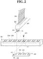
FIG. 2 shows the way how the hollow fiber membrane module is coupled to the cross bar of the frame structure according to one embodiment of the present invention; and -
FIG. 3 is a front view schematically showing the header of the hollow fiber membrane module and the cross bar of the frame structure coupled to each other. - Hereinafter, the filtering apparatuses according to the various embodiments of the present invention will be described in detail with reference to the annexed drawings.
-
FIG. 1 is a perspective view schematically showing the filtering apparatus according to one embodiment of the present invention. - As illustrated in
FIG. 1 , the filtering apparatus of the present invention comprises aframe structure 100 including first and second internal spaces IS1 and IS2, a first hollowfiber membrane module 200a installed in the first internal space IS 1, and a second hollowfiber membrane module 200b installed in the second internal space IS2. - Although only a single first hollow
fiber membrane module 200a and only a single second hollowfiber membrane module 200b are illustrated inFIG. 1 , according to one embodiment of the present invention, a plurality of first hollowfiber membrane modules 200a are arranged in parallel with each other in the first internal space IS1 of theframe structure 100 to form a first group. Likewise, a plurality of second hollowfiber membrane modules 200b are arranged in parallel with each other in the second internal space IS2 of theframe structure 100 to from a second group. - The
frame structure 100 comprises acentral cross pipe 121 and/or 122 disposed between the first group of hollowfiber membrane modules 200a and the second group of hollowfiber membrane modules 200b. The first and second group of hollowfiber membrane modules central cross pipe 121 and/or 122. Theframe structure 100 may further comprise a centralvertical member 111 in fluid communication with thecentral cross pipe 121 and/or 122. Theframe structure 100 may further comprise first andsecond cross pipes central cross pipe 121 and/or 122 therebetween, first and secondvertical members second cross pipes first aeration unit 140a which is in fluid communication with the firstvertical member 112 and disposed below the first group of hollowfiber membrane modules 200a, and asecond aeration unit 140b which is in fluid communication with the secondvertical member 113 and disposed below the second group of hollowfiber membrane modules 200b. Hereinafter, such structure of theframe structure 100 will be explained in more detail. - Each of the first and second hollow
fiber membrane modules upper header 210 of elongated shape having a first water collecting space, alower header 220 of elongated shape having a second water collecting space, andhollow fiber membranes 230 between the upper andlower headers hollow fiber membranes 230 are in fluid communication with the first and second water collecting spaces respectively. - The polymer resin that can be used for manufacturing the
hollow fiber membrane 230 comprises at least one of polysulfone resin, polyethersulfone resin, sulfonated polysulfone resin, polyvinylidene fluoride (PVDF) resin, polyacrylonitrile (PAN) resin, polyimide resin, polyamideimide resin, and polyesterimide resin. - The
hollow fiber membrane 230 may be a single-layer membrane or a composite membrane. If thehollow fiber membrane 230 is a composite membrane, it may comprise a tubular braid and a polymer thin film coated thereon. The tubular braid may be made of polyester or nylon. The polymer thin film comprises at least one of polysulfone resin, polyethersulfone resin, sulfonated polysulfone resin, polyvinylidene fluoride resin, polyacrylonitrile resin, polyimide resin, polyamideimide resin, and polyesterimide resin. - One end of the
hollow fiber membrane 230 is fixed to thebody 211 of theupper header 210 through the first fixing layer (not shown), and the other end thereof is fixed to thebody 221 of thelower header 220 through thesecond fixing layer 222. - The lumen of the
hollow fiber membrane 230 is in fluid communication with the first and second water collecting spaces of the upper andlower headers hollow fiber membrane 230, the permeate which has passed through thehollow fiber membrane 230 enters the first and second collecting spaces of the upper andlower headers second outlet pipes - Alternatively, only one of the upper and
lower headers - Further, each of the first and second hollow
fiber membrane modules first header 210 having the first water collecting space and thehollow fiber membranes 230. In this case, one end of thehollow fiber membrane 230 is in fluid communication with the first water collecting space and the other end is sealed. - As illustrated in
FIG. 1 , theframe structure 100 according to the one embodiment of the present invention comprisesvertical members hollow fiber membranes 230, andcross pipes vertical members lower headers hollow fiber membranes 230, respectively. - The
vertical members vertical members 111, a pair of firstvertical members 112 forming the first internal space IS1 together with the centralvertical members 111, and a pair of secondvertical members 113 forming the second internal space IS2 together with the centralvertical members 111. - The
cross pipes central pipe 121 which is supported by the centralvertical members 111 and in fluid communication with theupper headers 210 of the first and second hollowfiber membrane modules central cross pipe 122 which is supported by the centralvertical members 111 and in fluid communication with thelower headers 220 of the first and second hollowfiber membrane modules first cross pipe 123 supported by the firstvertical members 112, and asecond cross pipe 124 supported by the secondvertical members 113. - Particularly, the
first outlet pipes 213 of theupper headers 210 are inserted into thecoupling holes 121a of the firstcentral cross pipe 121 so that theupper headers 210 can be supported by the firstcentral cross pipe 121 and, at the same time, the first water collecting spaces of theupper headers 210 can be in fluid communication with the firstcentral cross pipe 121. - Similarly, the
second outlet pipes 223 of thelower headers 220 are inserted into thecoupling holes 122a of the secondcentral cross pipe 122 so that thelower headers 220 can be supported by the secondcentral cross pipe 122 and, at the same time, the second water collecting spaces of thelower headers 220 can be in fluid communication with the secondcentral cross pipe 122. - Each of the central
vertical members 111 is a pipe in fluid communication with at least one of the first and secondcentral cross pipes outlet port 111a to send the permeate produced by the first and second hollowfiber membrane modules - According to the aforementioned present invention, a filtering apparatus comprising a plurality of hollow
fiber membrane modules frame structure 100 with high packing density can be provided. Therefore, the the recover rate of a filtering system in which such filtering apparatuses are submerged in a fluid in a bath with a certain interval therebetween can be remarkably increased. - According to one embodiment of the present invention, each of the central
vertical members 111 is a pipe which is in fluid communication with both the first and secondcentral cross pipes hollow fiber membrane 230, the permeate passing through thehollow fiber membrane 230 is introduced into the first and second water collecting spaces of the upper andlower headers central cross pipes second outlet pipes outlet ports 111a of the centralvertical members 111. - According to another embodiment of the present invention, one of the two central vertical members 111 (hereinafter, 'first central vertical member') is a pipe which is in fluid communication with the first
central cross pipe 121, and the other of the two central vertical members 111 (hereinafter, 'second central vertical member') is a pipe which is in fluid communication with the secondcentral cross pipe 122. Hence, the permeate introduced into the first water collecting spaces of theupper headers 210 of the first and second hollowfiber membrane modules central cross pipe 121 and the first central vertical member sequentially, and then is discharged outside the filtering apparatus. On the other hand, the permeate introduced into the second water collecting spaces of thelower headers 220 of the first and second hollowfiber membrane modules central cross pipe 122 and the second central vertical member sequentially, and then is discharged outside the filtering apparatus. - According to the embodiment described above, since the water pressure applied to the feed water at the lower portion can be exploited for the filtration process, a negative pressure lower than the negative pressure applied to the
hollow fiber membrane 230 through theupper header 210 may be applied to thehollow fiber membrane 230 through thelower header 220 without lowering the filtration efficiency, and thus the efficiency of the filtration process can be maximized from the view point of energy. - As illustrated in
FIG. 1 , theframe structure 100 of the present invention may further comprise afirst aeration unit 140a disposed below the first hollowfiber membrane module 200a, and asecond aeration unit 140b disposed below the second hollowfiber membrane module 200b. - At least one of the first
vertical members 112 is a pipe which is in fluid communication with thefirst cross pipe 123 and thefirst aeration unit 140a. At least one of the secondvertical members 113 is a pipe which is in fluid communication with thesecond cross pipe 124 and thesecond aeration unit 140b. The first andsecond cross pipes inlet ports 123a and 124a respectively to receive the air for aeration cleaning from the outside. - That is, at least one of the first
vertical members 112 provides a path for the air to be supplied to thefirst aeration unit 140a, and at least one of the secondvertical members 113 provides a path for the air to be supplied to thesecond aeration unit 140b. - The
first aeration unit 140a may comprise a firstintermediate pipe 141a which is in fluid communication with at least one of the firstvertical members 112, and a plurality offirst aeration tubes 142a. Thesecond aeration unit 140b may comprise a secondintermediate pipe 141b which is in fluid communication with at least one of the secondvertical members 113, and a plurality ofsecond aeration tubes 142b. - The first and second
intermediate pipes vertical members second aeration tubes second aeration tubes second aeration tubes - According to such embodiment of the invention, the air for cleaning the first hollow
fiber membrane module 200a in the first internal space IS 1 is supplied to thefirst aeration unit 140a after passing through thefirst cross pipe 123 and at least one of the firstvertical members 112 sequentially. Further, the air for cleaning the second hollowfiber membrane module 200b in the second internal space IS2 is supplied to thesecond aeration unit 140b after passing through thesecond cross pipe 124 and at least one of the secondvertical members 113 sequentially. - Since the air for cleaning the first and second hollow
fiber membrane modules second aeration units fiber membrane modules - As illustrated in
FIG. 1 , theframe structure 100 of the present invention may further comprisehorizontal members lower headers fiber membrane modules - According to one embodiment of the present invention, the
horizontal members horizontal members 131, first lowerhorizontal members 133, second upperhorizontal members 132, and second lowerhorizontal members 134. The first upperhorizontal members 131 and first lowerhorizontal members 133 are corresponding to the first internal space IS 1, and the second upperhorizontal members 132 and second lowerhorizontal members 134 are corresponding to the second internal space IS2. - Each of the
horizontal members vertical members vertical members 111 respectively so that the distance between the firstvertical members 112 and centralvertical members 111 and the distance between the secondvertical members 113 and centralvertical members 111 can be kept constantly. - According to one embodiment of the present invention, the distance between the first
vertical members 112 and centralvertical members 111 and the distance between the secondvertical members 113 and centralvertical members 111 can be kept constantly by the first and secondintermediate pipes horizontal members intermediate pipes - As illustrated in
FIG. 1 , theframe structure 100 of the present invention comprisescross bars upper cross bar 127, a firstlower cross bar 125, a secondupper cross bar 128, and a secondlower cross bar 126. The upper andlower headers fiber membrane module 200a are coupled to the firstupper cross bar 127 and firstlower cross bar 125 respectively. The upper andlower headers fiber membrane module 200b are coupled to the secondupper cross bar 128 and secondlower cross bar 126 respectively. - The first and second hollow
fiber membrane modules frame structure 100 in such a manner that the longitudinal direction of the upper andlower headers hollow fiber membranes 230 are perpendicular to the longitudinal direction of the cross bars 125, 126, 127 and 128. - If the first and second hollow
fiber membrane modules upper headers 210 having the first water collecting spaces and thehollow fiber membranes 230, one ends of thehollow fiber membranes 230 are in fluid communication with the first water collecting spaces, the other ends are sealed, and it is possible to omit the first and second lower cross bars 125 and 126. - The first and second upper cross bars 127 and 128 may be combined to the lower portions of the first and
second cross pipes upper cross bar 127 directly to the firstvertical members 112, and the secondupper cross bar 128 directly to the secondvertical members 113. - The first and second upper cross bars 127 and 128 comprise first and
second ribs 127a respectively. Each of theupper headers 210 of the first and second hollowfiber membrane modules first ring member 214 at its one end. Thefirst ring member 214 is located opposite to thefirst outlet pipe 213. The first andsecond ribs 127a of the first and second upper cross bars 127 and 128 are inserted into thefirst ring members 214 of the first and second hollowfiber membrane modules upper headers 210 of the first and second hollowfiber membrane modules - The first
lower cross bar 125 is directly coupled to the firstvertical members 112, and the secondlower cross bar 126 is directly coupled to the secondvertical members 113. - The first and second lower cross bars 125 and 126 comprise first and
second ribs 125a and 126a respectively. Each of thelower headers 220 of the first and second hollowfiber membrane modules second ring member 224 at its one end. Thesecond ring member 224 is located opposite to thesecond outlet pipe 223. The first andsecond ribs 125a and 126a of the first and second lower cross bars 125 and 126 are inserted into thesecond ring members 224 of the first and second hollowfiber membrane modules lower headers 220 of the first and second hollowfiber membrane modules - According to one embodiment of the present invention, the first and second hollow
fiber membrane modules frame structure 100 by inserting the first andsecond outlet pipes lower headers fiber membrane modules coupling holes central cross pipes second ring members lower headers - The filtering apparatus according to one embodiment of the present invention further comprises first to
fourth stoppers 300 which are coupled respectively to the first andsecond ribs second ring members fiber membrane modules fiber membrane modules frame structure 100. - Hereinafter, referring to
FIG. 2 andFIG. 3 , the way how thelower header 220 of the first hollowfiber membrane module 200a is coupled to the firstlower cross bar 125 of theframe structure 100 according to one embodiment of the invention will be described in detail. - As illustrated in
FIG. 2 , the firstlower cross bar 125 comprises thefirst rib 125a protruding in longitudinal direction of thelower header 220 of the first hollowfiber membrane module 200a, and thelower header 220 comprises thesecond ring member 224 formed at the portion opposite to thesecond outlet pipe 223 and on the side opposite to thesecond fixing layer 222. - The
second ring member 224 of thelower header 220 has a through-hole TH. When the first hollowfiber membrane module 200a is installed in theframe structure 100, thefirst rib 125a of the firstlower cross bar 125 is inserted into the through-hole TH of thesecond ring member 224. - The
stopper 300 is coupled to a portion of thefirst rib 125a which has passed through the through-hole TH of thesecond ring member 224 so as to prevent the first hollowfiber membrane module 200a (more particularly, the lower header 220) from being separated from the frame structure 100 (more particularly, the first lower cross bar 125). - According to one embodiment of the present invention, as illustrated in
FIG. 2 , a first hole H1 is formed on the portion of thefirst rib 125a of the firstlower cross bar 125 passing through the through-hole TH of thesecond ring member 224 of thelower header 220, and thestopper 300 has a second hole H2 corresponding to the first hole H1. Thestopper 300 and thefirst rib 125a of the firstlower cross bar 125 are coupled with each other by means of abolt 410 and anut 420, thebolt 410 passing through the first and second holes H1 and H2. - The
stopper 300 may further comprise anauxiliary rib 310 to be inserted into the through-hole TH of thesecond ring member 224 of thelower header 220. - The size of the through-hole TH of the
second ring member 224 of thelower header 220 is so large that thefirst rib 125a of the firstlower cross bar 125 can be easily inserted thereinto and, subsequent to thefirst rib 125a, theauxiliary rib 310 of thestopper 300 is inserted into the through-hole TH of thesecond ring member 224 so that thefirst rib 125a of the firstlower cross bar 125 can be maintained tightly in the through-hole TH of thesecond ring member 224 of thelower header 220. Consequently, the relative vibration of the first hollowfiber membrane module 200a within theframe structure 100, which would otherwise occur during the aeration cleaning process, can be minimized. - Furthermore, since not only the
first rib 125a but also theauxiliary rib 310 are inserted into the through-hole TH of thesecond ring member 224, the power applied to thesecond ring member 224 of thelower header 220 of the first hollowfiber membrane module 200a during the aeration cleaning process can be dispersed to thefirst rib 125a andauxiliary rib 310. - Consequently, according to the present invention, the durability of the filtering apparatus can be improved, and both the damage of the hollow fiber membrane module and the separation of the hollow fiber membrane module from the frame structure can be prevented.
- Optionally, the
second ring member 224 may comprise an elastic member (not shown) capable of pressurizing theauxiliary rib 310 toward thefirst rib 125a while theribs first rib 125a of the firstlower cross bar 125 more tightly in the through-hole TH of thesecond ring member 224 of thelower header 220. - Since the filtering apparatus according to one embodiment of the invention comprises a plurality of first hollow
fiber membrane modules 200a and a plurality of second hollowfiber membrane modules 200b installed in theframe structure 100, the cross bars 125, 126, 127 and 128 of theframe structure 100 comprise a plurality of first andsecond ribs - The upper and
lower headers fiber membrane modules second ring members second ribs second ring member - For the convenience in installing the first and second hollow
fiber membrane modules frame structure 100, each of thestoppers 300 may be coupled to at least two of thefirst ribs ring members - Further, as shown in
FIG. 2 , eachstopper 300 may comprise a plurality ofauxiliary ribs 310, and theauxiliary ribs 310 may be inserted into the first andsecond ring members second ribs - According to one embodiment of the present invention, the first and second upper cross bars 127 and 128 further comprise a
first protrusion 127b between thefirst ribs 127a and a second protrusion between the second ribs (not shown) respectively, and the first and second lower cross bars 125 and 126 further comprise a first protrusion (125b) between thefirst ribs 125a and a second protrusion 126b between the second ribs 126a respectively. - Owing to the first and
second protrusions ring members ribs auxiliary ribs 310, andprotrusions - Further, as illustrated in
FIG. 2 , eachstopper 300 may further comprise an auxiliary protrusion(s) 320 between theauxiliary ribs 310. - Owing to the auxiliary protrusion(s) 320, the power applied to the
ring members ribs auxiliary ribs 310,protrusions - According to the aforementioned present invention, the relative vibration of the hollow
fiber membrane modules frame structure 100 which would otherwise occur during the aeration cleaning process can be minimized, and thus both the damage of the hollowfiber membrane modules fiber membrane modules frame structure 100 both of which could be caused by the relative vibration can be prevented.
Claims (12)
- A filtering apparatus comprising:a frame structure including first and second internal spaces;a first hollow fiber membrane module installed in the first internal space;anda second hollow fiber membrane module installed in the second internal space,wherein each of the first and second hollow fiber membrane modules comprises:an upper header;a lower header; anda hollow fiber membrane between the upper and lower headers,the frame structure comprises:vertical members having longitudinal direction parallel with the hollow fiber membrane; andcross pipes supported by the vertical members, the cross pipes having longitudinal direction perpendicular to the upper and lower headers and the hollow fiber membrane respectively,the vertical members comprises:a pair of central vertical members;a pair of first vertical members forming the first internal space together with the central vertical members; anda pair of second vertical members forming the second internal space together with the central vertical members,the cross pipes comprises:a first central cross pipe supported by the central vertical members, the first central cross pipe being in fluid communication with the upper headers of the first and second hollow fiber membrane modules; anda second central cross pipe supported by the central vertical members, the second central cross pipe being in fluid communication with the lower headers of the first and second hollow fiber membrane modules, andeach of the central vertical members is a pipe in fluid communication with at least one of the first and second central cross pipes and has an outlet port to send a permeate produced by the first and second hollow fiber membrane modules to an outside.
- The filtering apparatus of claim 1, wherein one of the central vertical members is a pipe in fluid communication only with the first central cross pipe, and
the other of the central vertical members is a pipe in fluid communication only with the second central cross pipe. - The filtering apparatus of claim 1, wherein the frame structure further comprises:a first aeration unit disposed below the first hollow fiber membrane module;anda second aeration unit disposed below the second hollow fiber membrane module,the cross pipes further comprises:a first cross pipe supported by the first vertical members; anda second cross pipe supported by the second vertical members,at least one of the first vertical members is a pipe in fluid communication with the first cross pipe and the first aeration unit,at least one of the second vertical members is a pipe in fluid communication with the second cross pipe and the second aeration unit, andeach of the first and second cross pipes has an inlet port to receive an air for aeration cleaning from an outside.
- The filtering apparatus of claim 1, wherein the frame structure further comprises:a first upper cross bar supported by the first vertical members; anda second upper cross bar supported by the second vertical members,the first and second upper cross bars include first and second ribs, respectively,each of the upper headers of the first and second hollow fiber membrane modules has a first ring member at one end thereof,the filtering apparatus further comprises first and second stoppers, andthe first and second ribs passing through the first ring members of the first and second hollow fiber membranes are coupled to the first and second stoppers, respectively, so that the first and second hollow fiber membranes can be prevented from being separated from the frame structure.
- The filtering apparatus of claim 4, wherein the first and second stoppers comprise first and second auxiliary ribs, respectively, the first and second auxiliary ribs inserted into the first ring members, respectively.
- The filtering apparatus of claim 4, wherein portions of the first and second ribs passing through the first ring members respectively are coupled to the first and second stoppers respectively by means of bolts and nuts.
- The filtering apparatus of claim 6, wherein the first and second upper cross bars comprise a plurality of the first ribs and a plurality of the second ribs, respectively,
the filtering apparatus comprises a plurality of the first hollow fiber membrane modules and a plurality of the second hollow fiber membrane modules,
each of the first and second ribs is inserted into the first ring member corresponding thereto,
the first stopper is coupled to at least two of the first ribs, and
the second stopper is coupled to at least two of the second ribs. - The filtering apparatus of claim 7, wherein the first and second stoppers comprise a plurality of first auxiliary ribs and a plurality of second auxiliary ribs, respectively, and
each of the first and second auxiliary ribs is inserted into the first ring member corresponding thereto. - The filtering apparatus of claim 8, wherein the first and second upper cross bars further comprise a first protrusion between the first ribs and a second protrusion between the second ribs, respectively, and
the first and second stoppers further comprise a first auxiliary protrusion between the first auxiliary ribs and a second auxiliary protrusions between the second auxiliary ribs, respectively. - A filtering apparatus comprising:a frame structure;a first group of hollow fiber membrane modules arranged in parallel with each other in the frame structure; anda second group of hollow fiber membrane modules arranged in parallel with each other in the frame structure,wherein the frame structure comprises a central cross pipe disposed between the first group of hollow fiber membrane modules and the second group of hollow fiber membrane modules, andthe first and second groups of hollow fiber membrane modules are in fluid communication with the central cross pipe.
- The filtering apparatus of claim 10, wherein the frame structure further comprises a central vertical member in fluid communication with the central cross pipe.
- The filtering apparatus of claim 10, wherein the frame structure further comprises:first and second cross pipes with the central cross pipe therebetween;first and second vertical members in fluid communication with the first and second cross pipes, respectively;a first aeration unit in fluid communication with the first vertical member, the first aeration unit disposed below the first group of hollow fiber membrane modules; anda second aeration unit in fluid communication with the second vertical member, the second aeration unit disposed below the second group of hollow fiber membrane modules.
Applications Claiming Priority (2)
| Application Number | Priority Date | Filing Date | Title |
|---|---|---|---|
| KR20140036690 | 2014-03-28 | ||
| PCT/KR2015/002898 WO2015147536A1 (en) | 2014-03-28 | 2015-03-25 | Filtering apparatus |
Publications (2)
| Publication Number | Publication Date |
|---|---|
| EP3124105A1 true EP3124105A1 (en) | 2017-02-01 |
| EP3124105A4 EP3124105A4 (en) | 2017-11-29 |
Family
ID=54195972
Family Applications (1)
| Application Number | Title | Priority Date | Filing Date |
|---|---|---|---|
| EP15767939.0A Withdrawn EP3124105A4 (en) | 2014-03-28 | 2015-03-25 | Filtering apparatus |
Country Status (6)
| Country | Link |
|---|---|
| US (1) | US20170120199A1 (en) |
| EP (1) | EP3124105A4 (en) |
| KR (1) | KR102236176B1 (en) |
| CN (1) | CN106102882B (en) |
| SG (1) | SG11201607948VA (en) |
| WO (1) | WO2015147536A1 (en) |
Families Citing this family (7)
| Publication number | Priority date | Publication date | Assignee | Title |
|---|---|---|---|---|
| JPWO2017057501A1 (en) * | 2015-10-01 | 2018-07-19 | 住友電気工業株式会社 | Membrane separation activated sludge treatment method and membrane separation activated sludge treatment system |
| KR102134316B1 (en) * | 2015-11-10 | 2020-07-15 | 코오롱인더스트리 주식회사 | Filtering Membrane Module and Filtering Apparatus |
| KR101902638B1 (en) * | 2016-11-30 | 2018-09-28 | 두산중공업 주식회사 | Membrane filtration system |
| KR101902640B1 (en) * | 2016-11-30 | 2018-09-28 | 두산중공업 주식회사 | Membrane filtration system |
| JPWO2018131150A1 (en) * | 2017-01-13 | 2019-11-07 | 住友電気工業株式会社 | Filtration device |
| CN110548404B (en) * | 2019-08-27 | 2022-04-01 | 武汉艾科滤膜技术有限公司 | Hollow fiber membrane module |
| KR102681393B1 (en) * | 2021-11-29 | 2024-07-04 | (주)하이필엠 | Filtration Apparatus and Filtration System Comprising The Same |
Family Cites Families (8)
| Publication number | Priority date | Publication date | Assignee | Title |
|---|---|---|---|---|
| US7037426B2 (en) * | 2000-05-04 | 2006-05-02 | Zenon Environmental Inc. | Immersed membrane apparatus |
| CA2348186A1 (en) * | 2001-05-18 | 2002-11-18 | Zenon Environmental Inc. | Immersed membrane module |
| ATE395127T1 (en) * | 2003-03-05 | 2008-05-15 | Hydranautics | SUBMERSIBLE MEMBRANE MODULE WITH INTERCHANGEABLE MEMBRANE ELEMENTS |
| KR100552712B1 (en) * | 2004-06-08 | 2006-02-20 | 현대엔지니어링 주식회사 | High efficiency membrane unit for wastewater treatment |
| KR100974912B1 (en) * | 2008-05-23 | 2010-08-09 | (주)대우건설 | Piping integrated membrane frame structure and membrane unit using same |
| KR101321670B1 (en) * | 2011-08-05 | 2013-10-22 | 김백암 | A Membrane Module with an Air Pipe and Suction Pipe Frame Capable of High Integration |
| KR101364344B1 (en) * | 2012-12-14 | 2014-02-19 | 코오롱인더스트리 주식회사 | Filtering apparatus |
| KR101364362B1 (en) * | 2012-12-28 | 2014-02-19 | 코오롱인더스트리 주식회사 | Filtering apparatus |
-
2015
- 2015-03-25 WO PCT/KR2015/002898 patent/WO2015147536A1/en not_active Ceased
- 2015-03-25 KR KR1020150041154A patent/KR102236176B1/en active Active
- 2015-03-25 US US15/129,529 patent/US20170120199A1/en not_active Abandoned
- 2015-03-25 EP EP15767939.0A patent/EP3124105A4/en not_active Withdrawn
- 2015-03-25 CN CN201580013128.4A patent/CN106102882B/en not_active Expired - Fee Related
- 2015-03-25 SG SG11201607948VA patent/SG11201607948VA/en unknown
Also Published As
| Publication number | Publication date |
|---|---|
| CN106102882A (en) | 2016-11-09 |
| WO2015147536A1 (en) | 2015-10-01 |
| KR20150112845A (en) | 2015-10-07 |
| KR102236176B1 (en) | 2021-04-05 |
| EP3124105A4 (en) | 2017-11-29 |
| SG11201607948VA (en) | 2016-11-29 |
| CN106102882B (en) | 2019-04-02 |
| US20170120199A1 (en) | 2017-05-04 |
Similar Documents
| Publication | Publication Date | Title |
|---|---|---|
| US9504965B2 (en) | Filtering apparatus | |
| US20170120199A1 (en) | Filtering apparatus | |
| US8506805B2 (en) | System and method for installing filtering membrane module to frame structure | |
| US9795904B2 (en) | Filtering membrane module and filtering apparatus having the same | |
| US20050126966A1 (en) | Membrane separation device and membrane separation method | |
| JP2013052386A (en) | Hollow fiber membrane module and hollow fiber membrane module unit | |
| KR20050047230A (en) | Submerged hollow fiber membrane module | |
| US8623208B2 (en) | Hollow fiber membrane module and puller used therefor | |
| KR20120111207A (en) | Filtration memebrane module and filtration system having the same | |
| CN103842056B (en) | Aeration unit and include its defecator | |
| KR101559122B1 (en) | Membrane appratus for water treatment that is easily assembled and disassembled | |
| US20150217214A1 (en) | Filtering apparatus | |
| CN102361681B (en) | Hollow fiber membrane module, filter device using the same, and method of manufacturing the filter device | |
| KR20160080010A (en) | Pressurized-type Hollow Fiber Membrane Module | |
| US20120097596A1 (en) | Filtering system | |
| KR20140071617A (en) | Filtering Apparatus | |
| KR101692689B1 (en) | System and Method for Filtering Using Positive Pressure Type Module | |
| KR20180035130A (en) | Header, Hollow Fiber Membrane Module Comprising The Same, and Filtering Apparatus Comprising The Same | |
| KR20170079917A (en) | Filtration Apparatus and Aeration Unit Therefor | |
| KR101777554B1 (en) | Filtering Apparatus and Hollow Fiber Membrane Module Therefor | |
| KR20150089195A (en) | Filtering Apparatus and Aeration Unit Therefor | |
| KR20150078446A (en) | Submerged-Type Filtration Apparatus | |
| KR20150068125A (en) | Submerged-Type Filtration Apparatus |
Legal Events
| Date | Code | Title | Description |
|---|---|---|---|
| PUAI | Public reference made under article 153(3) epc to a published international application that has entered the european phase |
Free format text: ORIGINAL CODE: 0009012 |
|
| 17P | Request for examination filed |
Effective date: 20160914 |
|
| AK | Designated contracting states |
Kind code of ref document: A1 Designated state(s): AL AT BE BG CH CY CZ DE DK EE ES FI FR GB GR HR HU IE IS IT LI LT LU LV MC MK MT NL NO PL PT RO RS SE SI SK SM TR |
|
| AX | Request for extension of the european patent |
Extension state: BA ME |
|
| DAV | Request for validation of the european patent (deleted) | ||
| DAX | Request for extension of the european patent (deleted) | ||
| RIC1 | Information provided on ipc code assigned before grant |
Ipc: C02F 1/44 20060101ALI20171018BHEP Ipc: B01D 63/02 20060101ALI20171018BHEP Ipc: B01D 69/10 20060101ALI20171018BHEP Ipc: B01D 69/08 20060101AFI20171018BHEP Ipc: B01D 63/04 20060101ALI20171018BHEP |
|
| A4 | Supplementary search report drawn up and despatched |
Effective date: 20171026 |
|
| RAP1 | Party data changed (applicant data changed or rights of an application transferred) |
Owner name: KOLON INDUSTRIES, INC. |
|
| STAA | Information on the status of an ep patent application or granted ep patent |
Free format text: STATUS: THE APPLICATION HAS BEEN WITHDRAWN |
|
| 17Q | First examination report despatched |
Effective date: 20200407 |
|
| 18W | Application withdrawn |
Effective date: 20200429 |