EP3124078A1 - Improved radiotherapeutic apparatus and method of control - Google Patents
Improved radiotherapeutic apparatus and method of control Download PDFInfo
- Publication number
- EP3124078A1 EP3124078A1 EP16179685.9A EP16179685A EP3124078A1 EP 3124078 A1 EP3124078 A1 EP 3124078A1 EP 16179685 A EP16179685 A EP 16179685A EP 3124078 A1 EP3124078 A1 EP 3124078A1
- Authority
- EP
- European Patent Office
- Prior art keywords
- pulses
- pulse train
- pulse
- permitted
- marked
- Prior art date
- Legal status (The legal status is an assumption and is not a legal conclusion. Google has not performed a legal analysis and makes no representation as to the accuracy of the status listed.)
- Granted
Links
Images

Classifications
-
- A—HUMAN NECESSITIES
- A61—MEDICAL OR VETERINARY SCIENCE; HYGIENE
- A61N—ELECTROTHERAPY; MAGNETOTHERAPY; RADIATION THERAPY; ULTRASOUND THERAPY
- A61N5/00—Radiation therapy
- A61N5/10—X-ray therapy; Gamma-ray therapy; Particle-irradiation therapy
-
- A—HUMAN NECESSITIES
- A61—MEDICAL OR VETERINARY SCIENCE; HYGIENE
- A61N—ELECTROTHERAPY; MAGNETOTHERAPY; RADIATION THERAPY; ULTRASOUND THERAPY
- A61N5/00—Radiation therapy
- A61N5/10—X-ray therapy; Gamma-ray therapy; Particle-irradiation therapy
- A61N5/103—Treatment planning systems
-
- A—HUMAN NECESSITIES
- A61—MEDICAL OR VETERINARY SCIENCE; HYGIENE
- A61N—ELECTROTHERAPY; MAGNETOTHERAPY; RADIATION THERAPY; ULTRASOUND THERAPY
- A61N5/00—Radiation therapy
- A61N5/10—X-ray therapy; Gamma-ray therapy; Particle-irradiation therapy
- A61N5/1042—X-ray therapy; Gamma-ray therapy; Particle-irradiation therapy with spatial modulation of the radiation beam within the treatment head
-
- A—HUMAN NECESSITIES
- A61—MEDICAL OR VETERINARY SCIENCE; HYGIENE
- A61N—ELECTROTHERAPY; MAGNETOTHERAPY; RADIATION THERAPY; ULTRASOUND THERAPY
- A61N5/00—Radiation therapy
- A61N5/10—X-ray therapy; Gamma-ray therapy; Particle-irradiation therapy
- A61N5/1042—X-ray therapy; Gamma-ray therapy; Particle-irradiation therapy with spatial modulation of the radiation beam within the treatment head
- A61N5/1045—X-ray therapy; Gamma-ray therapy; Particle-irradiation therapy with spatial modulation of the radiation beam within the treatment head using a multi-leaf collimator, e.g. for intensity modulated radiation therapy or IMRT
-
- A—HUMAN NECESSITIES
- A61—MEDICAL OR VETERINARY SCIENCE; HYGIENE
- A61N—ELECTROTHERAPY; MAGNETOTHERAPY; RADIATION THERAPY; ULTRASOUND THERAPY
- A61N5/00—Radiation therapy
- A61N5/10—X-ray therapy; Gamma-ray therapy; Particle-irradiation therapy
- A61N5/1042—X-ray therapy; Gamma-ray therapy; Particle-irradiation therapy with spatial modulation of the radiation beam within the treatment head
- A61N5/1045—X-ray therapy; Gamma-ray therapy; Particle-irradiation therapy with spatial modulation of the radiation beam within the treatment head using a multi-leaf collimator, e.g. for intensity modulated radiation therapy or IMRT
- A61N5/1047—X-ray therapy; Gamma-ray therapy; Particle-irradiation therapy with spatial modulation of the radiation beam within the treatment head using a multi-leaf collimator, e.g. for intensity modulated radiation therapy or IMRT with movement of the radiation head during application of radiation, e.g. for intensity modulated arc therapy or IMAT
-
- A—HUMAN NECESSITIES
- A61—MEDICAL OR VETERINARY SCIENCE; HYGIENE
- A61N—ELECTROTHERAPY; MAGNETOTHERAPY; RADIATION THERAPY; ULTRASOUND THERAPY
- A61N5/00—Radiation therapy
- A61N5/10—X-ray therapy; Gamma-ray therapy; Particle-irradiation therapy
- A61N5/1048—Monitoring, verifying, controlling systems and methods
-
- A—HUMAN NECESSITIES
- A61—MEDICAL OR VETERINARY SCIENCE; HYGIENE
- A61N—ELECTROTHERAPY; MAGNETOTHERAPY; RADIATION THERAPY; ULTRASOUND THERAPY
- A61N5/00—Radiation therapy
- A61N5/10—X-ray therapy; Gamma-ray therapy; Particle-irradiation therapy
- A61N5/1048—Monitoring, verifying, controlling systems and methods
- A61N2005/1074—Details of the control system, e.g. user interfaces
-
- A—HUMAN NECESSITIES
- A61—MEDICAL OR VETERINARY SCIENCE; HYGIENE
- A61N—ELECTROTHERAPY; MAGNETOTHERAPY; RADIATION THERAPY; ULTRASOUND THERAPY
- A61N5/00—Radiation therapy
- A61N5/10—X-ray therapy; Gamma-ray therapy; Particle-irradiation therapy
- A61N2005/1085—X-ray therapy; Gamma-ray therapy; Particle-irradiation therapy characterised by the type of particles applied to the patient
- A61N2005/1089—Electrons
-
- A—HUMAN NECESSITIES
- A61—MEDICAL OR VETERINARY SCIENCE; HYGIENE
- A61N—ELECTROTHERAPY; MAGNETOTHERAPY; RADIATION THERAPY; ULTRASOUND THERAPY
- A61N5/00—Radiation therapy
- A61N5/10—X-ray therapy; Gamma-ray therapy; Particle-irradiation therapy
- A61N2005/1092—Details
-
- A—HUMAN NECESSITIES
- A61—MEDICAL OR VETERINARY SCIENCE; HYGIENE
- A61N—ELECTROTHERAPY; MAGNETOTHERAPY; RADIATION THERAPY; ULTRASOUND THERAPY
- A61N5/00—Radiation therapy
- A61N5/10—X-ray therapy; Gamma-ray therapy; Particle-irradiation therapy
- A61N5/1048—Monitoring, verifying, controlling systems and methods
- A61N5/1075—Monitoring, verifying, controlling systems and methods for testing, calibrating, or quality assurance of the radiation treatment apparatus
Definitions
- the present invention relates to radiotherapeutic apparatus and a method therefor.
- a radiotherapy radiation source may be provided by, for example, a radio-frequency (RF) waveguide which may accelerate electrons to a desired energy level, either to subsequently produce x-rays by arranging for the electrons to collide with a tungsten target, for example, or for direct use in electron therapy.
- RF radio-frequency
- WO2007/124760 describes existing VMAT therapies, in which the dose rate is used as a variable in order to match the maximum speed of the moving machine axes and therefore create the specified dose rate, expressed as mu/mm or mu/°.
- a radiotherapeutic apparatus comprising a source of radiation able to issue pulses of radiation at a base frequency, and a control apparatus arranged to permit or suppress pulses according to a pulse pattern chosen to achieve a selected time-averaged power level, the chosen pulse pattern being one selected from a plurality of pulse patterns, the plurality including at least one pattern consisting of a train of pulses that includes, relative to the base frequency, at least every n th and every m th pulse, where n ⁇ m and the n th and m th pulse are non-coincident.
- the pulse pattern generated by that radiotherapeutic apparatus is able to modulate the output dose rate much more precisely than in previous radiotherapeutic apparatus, and thus reduce treatment times.
- the pulse pattern generated by that invention could, under certain circumstances, include several consecutive permitted pulses followed by several consecutive suppressed pulses.
- Example pulse train patterns resulting from the apparatus of our '887 are shown in Figure 1 , and that drawing is described in more detail below. In that drawing it can be seen that permitted and suppressed pulses are sometimes grouped into blocks of consecutive permitted pulses and suppressed pulses.
- the efficiency and lifetime of an RF waveguide for radiotherapeutic apparatus can be improved if, for a selected time-averaged power level, permitted and suppressed pulses can be spaced more evenly within a pulse train, thus minimising fluctuation of the electrical power supplied to the waveguide.
- the present invention therefore provides a radiotherapy apparatus comprising a source of radiation able to issue pulses of radiation at a base frequency, and a control apparatus arranged to achieve a time-averaged power level of x, where x is a value between 0 and 1 representing a proportion of a maximum power output of the apparatus, by permitting an n th pulse if n is equal to the rounded value of (an integer times 1/x).
- the rounding operation applied to the integer multiples of 1/x can be a classical rounding to the nearest integer operation, i.e. taking the integer part only of the value after adding one half, or it can be a simpler operation of simply taking the integer part only.
- adding a fixed value prior to taking the integer part simply shifts the chosen pulse forward or backward in a sequence and does not significantly affect the overall result, provided that a sufficient number of pulses are issued. For simplicity, therefore, it will usually be easiest simply to take the integer part.
- the sequence can be allowed to run indefinitely, or it can be repeated periodically in a pulse train pattern in order to prevent the numbers involved from overflowing. Generally, a longer sequence allows a correspondingly finer level of control over the power level, so a pattern of between 10 1 and 10 7 pulses is likely to be sufficient, preferably between 10 1 and 10 3 pulses.
- a pattern can be derived by defining a number of available slots, M, each slot being capable of being marked as a permitted pulse or a suppressed pulse, the number of permitted and suppressed pulses being selected so that the pattern has a selected number of permitted pulses, Q, the pattern being derived by:
- each permitted pulse results in the emission, from the radiation source, of a particular dose of radiotherapeutic energy (for example x-rays or electrons), and the number of permitted pulses is selected so that over the course of the pulse train a radiation dose is emitted, the permitted pulses are approximately evenly spaced within the sequence or pulse train.
- radiotherapeutic energy for example x-rays or electrons
- a further advantage of the present invention is that it reduces the number of and complexity of calculations required to determine a suitable pulse train, compared with previous techniques. This can either speed up calculations, or enable less complex calculation circuitry to be used.
- the control apparatus may store one or more pulse train patterns in a table of a memory. This allows the pulse train pattern(s) to be calculated in advance rather than in real time. After storage, pulse train patterns may be selected without the need to calculate a suitable pulse train pattern each time.
- a common form of radiotherapeutic apparatus comprises an RF waveguide and a control apparatus.
- the present invention also relates to a method of providing pulses to a control apparatus for a radiotherapy apparatus, the radiotherapy apparatus comprising a source of radiation able to issue a sequence of pulses of radiation at a base frequency, and a control apparatus arranged to achieve a time-averaged power level of x, where x is a value between 0 and 1 representing a proportion of a maximum power output of the radiotherapy apparatus, the method comprising permitting an n th pulse if n is equal to the rounded value of (an integer times 1/x).
- the rounding operation applied to the integer multiples of 1/x can be a classical rounding to the nearest integer operation, i.e. taking the integer part only of the value after adding one half, or it can be a simpler operation of simply taking the integer part only.
- adding a fixed value prior to taking the integer part simply shifts the chosen pulse forward or backward in a sequence and does not affect the overall result, provided that a sufficient number of pulses are issued. For simplicity, therefore, it will usually be easiest simply to take the integer part.
- the sequence can be allowed to run indefinitely, or it can be repeated periodically in a pulse train pattern in order to prevent the numbers involved from overflowing. Generally, a longer pattern allows a correspondingly finer level of control over the power level, so a pattern of between 10 1 and 10 7 pulses is likely to be sufficient, preferably between 10 2 and 10 3 pulses.
- a pattern can be derived by defining a number of available slots, M, each slot being capable of being marked as a permitted pulse or a suppressed pulse, the number of permitted and suppressed pulses being selected so that the pattern has a selected number of permitted pulses, Q, the method comprising the steps of:
- the method may further comprise the step of generating a series of radiotherapeutic doses to a patient, each dose being generated according to the pulse train pattern.
- the control apparatus may store one or more pulse train patterns in a table of a memory. This allows the pulse train pattern(s) to be calculated in advance rather than in real time. After storage, pulse train patterns may be selected without the need to derive a suitable pulse train pattern each time.
- Radiotherapeutic apparatus may operate in an "open loop” or a "closed loop” arrangement.
- a dose provided by a pulse provided by a radiation source is known, to a degree of precision, and thus the number or rate of pulses to be provided to produce a desired dose rate can be calculated. There is some variability in the dose per pulse generated, however. Thus, in an open loop arrangement there is a degree of uncertainty in the actual dose rate being provided to a patient.
- the dose rate being provided is measured, so that the output from the radiotherapeutic apparatus can be calibrated.
- the calibration steps may be as follows: selecting a dose rate corresponding to a desired dose rate, generating a pulse rate pattern corresponding to the selected dose rate, applying the pulse rate pattern to the control apparatus and thus to the radiotherapeutic apparatus, measuring the actual dose rate generated, and varying the selected dose rate, if necessary, to increase or decrease the actual dose rate generated.
- the actual dose rate generated may be measured by using an ion chamber beneath an x-ray target, for example.
- a feedback mechanism may be provided, to compare the actual dose rate generated with the selected dose rate.
- a dose rate may be described in terms of monitor units per unit time.
- the method of the present invention may further comprise the steps of: measuring an output from the radiation source; comparing the output with a desired output; and using the result of the comparison between the measured output and the desired output to vary the selected number of permitted pulses, Q.
- the apparatus of the present invention may further comprise means for comparing an output of the radiation source with a desired output.
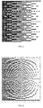
- a graphical representation of a known set of pulse train patterns is set out as a series of "pixels", so that a dark pixel represents a permitted pulse, and a light pixel represents a suppressed pulse.
- the vertical axis represents possible pulse slots. In this way, in the leftmost vertical column, all pixels are dark, representing that each possible pulse slot is marked as permitted. In the rightmost vertical column, nearly all the pixels are light, representing that nearly all possible pulse slots are marked as suppressed.
- Figure 2 is a graphical representation, in a similar style to that of Figure 1 .
- the distribution of permitted and suppressed pulses, as represented by dark and light pixels is according to the method and apparatus of the present invention.
- the arrangement of pixels (and thus pulses) is similar, because there are so few suppressed and permitted pulses in the relevant pulse train pattern, respectively.
- the dark and light pixels (and thus the permitted and suppressed pulses) are substantially evenly spaced within the pulse train pattern.
- pulse slots 2, 4, 6, 8, 10, 12, 14, and 16 are marked as permitted pulses, and the remaining pulse slots are marked as suppressed pulses.
- 8 pulses are issued out of every 16 slots, and the pulses are evenly spaced.
- pulse slots 5, 9, 14, 18, 23, 27, and 32 are marked as permitted pulses, and the remaining pulse slots are marked as suppressed pulses.
- a total of 7 pulses are issued out of every 32 slots, and (again) the pulses are relatively evenly spaced with the gap varying by only ⁇ 1 slot.
- Example 1 The spacing of the permitted pulses within the resulting pulse train pattern in each of the above examples is approximately even.
- the permitted pulses are all spaced apart by one suppressed pulse, and in Example 2, the permitted pulses are spaced apart by four to five suppressed pulses.
- Figure 3 is a table showing a worked example of a pulse train with 16 possible slots.
- the next column to the right shows incrementing values of Q, from 1 in the first row next to the uppermost M value, incrementing in each row downwards, reaching 16 in the lowermost row of the table.
- the value of P determines which pulse train pattern slots are marked as permitted, and which are marked as suppressed.
- pulse slot positions are numbered in the row above the first row of the worked example, i.e. incrementally from 1 to 16.
Landscapes
- Health & Medical Sciences (AREA)
- Engineering & Computer Science (AREA)
- Biomedical Technology (AREA)
- Pathology (AREA)
- Nuclear Medicine, Radiotherapy & Molecular Imaging (AREA)
- Radiology & Medical Imaging (AREA)
- Life Sciences & Earth Sciences (AREA)
- Animal Behavior & Ethology (AREA)
- General Health & Medical Sciences (AREA)
- Public Health (AREA)
- Veterinary Medicine (AREA)
- Radiation-Therapy Devices (AREA)
Abstract
Description
- The present invention relates to radiotherapeutic apparatus and a method therefor.
- A radiotherapy radiation source may be provided by, for example, a radio-frequency (RF) waveguide which may accelerate electrons to a desired energy level, either to subsequently produce x-rays by arranging for the electrons to collide with a tungsten target, for example, or for direct use in electron therapy.
- Our
WO2007/124760 describes existing VMAT therapies, in which the dose rate is used as a variable in order to match the maximum speed of the moving machine axes and therefore create the specified dose rate, expressed as mu/mm or mu/°. - Our
WO2011/050887 sets out that a drawback of previously-known VMAT therapies is the longer treatment required because only a limited range of dose rates was available. That document proposed a radiotherapeutic apparatus comprising a source of radiation able to issue pulses of radiation at a base frequency, and a control apparatus arranged to permit or suppress pulses according to a pulse pattern chosen to achieve a selected time-averaged power level, the chosen pulse pattern being one selected from a plurality of pulse patterns, the plurality including at least one pattern consisting of a train of pulses that includes, relative to the base frequency, at least every nth and every mth pulse, where n≠m and the nth and mth pulse are non-coincident. - The pulse pattern generated by that radiotherapeutic apparatus is able to modulate the output dose rate much more precisely than in previous radiotherapeutic apparatus, and thus reduce treatment times.
- However, the pulse pattern generated by that invention could, under certain circumstances, include several consecutive permitted pulses followed by several consecutive suppressed pulses. Example pulse train patterns resulting from the apparatus of our '887 are shown in
Figure 1 , and that drawing is described in more detail below. In that drawing it can be seen that permitted and suppressed pulses are sometimes grouped into blocks of consecutive permitted pulses and suppressed pulses. - The efficiency and lifetime of an RF waveguide for radiotherapeutic apparatus can be improved if, for a selected time-averaged power level, permitted and suppressed pulses can be spaced more evenly within a pulse train, thus minimising fluctuation of the electrical power supplied to the waveguide.
- The present invention therefore provides a radiotherapy apparatus comprising a source of radiation able to issue pulses of radiation at a base frequency, and a control apparatus arranged to achieve a time-averaged power level of x, where x is a value between 0 and 1 representing a proportion of a maximum power output of the apparatus, by permitting an nth pulse if n is equal to the rounded value of (an
integer times 1/x). - The rounding operation applied to the integer multiples of 1/x can be a classical rounding to the nearest integer operation, i.e. taking the integer part only of the value after adding one half, or it can be a simpler operation of simply taking the integer part only. In fact, adding a fixed value prior to taking the integer part simply shifts the chosen pulse forward or backward in a sequence and does not significantly affect the overall result, provided that a sufficient number of pulses are issued. For simplicity, therefore, it will usually be easiest simply to take the integer part.
- The sequence can be allowed to run indefinitely, or it can be repeated periodically in a pulse train pattern in order to prevent the numbers involved from overflowing. Generally, a longer sequence allows a correspondingly finer level of control over the power level, so a pattern of between 101 and 107 pulses is likely to be sufficient, preferably between 101 and 103 pulses.
- Where a pulse train pattern is repeated periodically, a pattern can be derived by defining a number of available slots, M, each slot being capable of being marked as a permitted pulse or a suppressed pulse, the number of permitted and suppressed pulses being selected so that the pattern has a selected number of permitted pulses, Q, the pattern being derived by:
- i) dividing M by Q to calculate a factor P;
- ii) calculating a series of incremented multiples of P, PN = NP, until N = Q, where N increments from one;
- iii) rounding (as above) the values of PN to produce a set of values RN ;
- iv) marking each pulse train pattern slot so that slot positions which correspond to the values of RN are marked as permitted pulses, and all other slot positions are marked as suppressed pulses.
- For a sequence, or a pulse train pattern having particular number of pulse slots, where each permitted pulse results in the emission, from the radiation source, of a particular dose of radiotherapeutic energy (for example x-rays or electrons), and the number of permitted pulses is selected so that over the course of the pulse train a radiation dose is emitted, the permitted pulses are approximately evenly spaced within the sequence or pulse train. The advantage of this approximately even spacing is to minimise fluctuation of the electrical power supplied to a waveguide.
- A further advantage of the present invention is that it reduces the number of and complexity of calculations required to determine a suitable pulse train, compared with previous techniques. This can either speed up calculations, or enable less complex calculation circuitry to be used.
- The control apparatus may store one or more pulse train patterns in a table of a memory. This allows the pulse train pattern(s) to be calculated in advance rather than in real time. After storage, pulse train patterns may be selected without the need to calculate a suitable pulse train pattern each time.
- A common form of radiotherapeutic apparatus comprises an RF waveguide and a control apparatus.
- The present invention also relates to a method of providing pulses to a control apparatus for a radiotherapy apparatus, the radiotherapy apparatus comprising a source of radiation able to issue a sequence of pulses of radiation at a base frequency, and a control apparatus arranged to achieve a time-averaged power level of x, where x is a value between 0 and 1 representing a proportion of a maximum power output of the radiotherapy apparatus, the method comprising permitting an nth pulse if n is equal to the rounded value of (an
integer times 1/x). - As above, the rounding operation applied to the integer multiples of 1/x can be a classical rounding to the nearest integer operation, i.e. taking the integer part only of the value after adding one half, or it can be a simpler operation of simply taking the integer part only. In fact, adding a fixed value prior to taking the integer part simply shifts the chosen pulse forward or backward in a sequence and does not affect the overall result, provided that a sufficient number of pulses are issued. For simplicity, therefore, it will usually be easiest simply to take the integer part.
- The sequence can be allowed to run indefinitely, or it can be repeated periodically in a pulse train pattern in order to prevent the numbers involved from overflowing. Generally, a longer pattern allows a correspondingly finer level of control over the power level, so a pattern of between 101 and 107 pulses is likely to be sufficient, preferably between 102 and 103 pulses.
- Where a pulse train pattern is repeated periodically, a pattern can be derived by defining a number of available slots, M, each slot being capable of being marked as a permitted pulse or a suppressed pulse, the number of permitted and suppressed pulses being selected so that the pattern has a selected number of permitted pulses, Q, the method comprising the steps of:
- i) dividing M by Q to calculate a factor P;
- ii) calculating a series of incremented multiples of P, PN = NP, until N = Q, where N increments from one;
- iii) rounding (as above) the values of PN to produce a set of values RN ;
- iv) marking each pulse train pattern slot so that slot positions which correspond to the values of RN are marked as permitted pulses, and all other slot positions are marked as suppressed pulses, so that a pulse train pattern is generated.
- The method may further comprise the step of generating a series of radiotherapeutic doses to a patient, each dose being generated according to the pulse train pattern.
- The control apparatus may store one or more pulse train patterns in a table of a memory. This allows the pulse train pattern(s) to be calculated in advance rather than in real time. After storage, pulse train patterns may be selected without the need to derive a suitable pulse train pattern each time.
- Radiotherapeutic apparatus may operate in an "open loop" or a "closed loop" arrangement. In an open loop arrangement, a dose provided by a pulse provided by a radiation source is known, to a degree of precision, and thus the number or rate of pulses to be provided to produce a desired dose rate can be calculated. There is some variability in the dose per pulse generated, however. Thus, in an open loop arrangement there is a degree of uncertainty in the actual dose rate being provided to a patient.
- In a closed loop arrangement, the dose rate being provided is measured, so that the output from the radiotherapeutic apparatus can be calibrated. The calibration steps may be as follows: selecting a dose rate corresponding to a desired dose rate, generating a pulse rate pattern corresponding to the selected dose rate, applying the pulse rate pattern to the control apparatus and thus to the radiotherapeutic apparatus, measuring the actual dose rate generated, and varying the selected dose rate, if necessary, to increase or decrease the actual dose rate generated. The actual dose rate generated may be measured by using an ion chamber beneath an x-ray target, for example.
- A feedback mechanism may be provided, to compare the actual dose rate generated with the selected dose rate. A dose rate may be described in terms of monitor units per unit time.
- Thus, the method of the present invention may further comprise the steps of: measuring an output from the radiation source; comparing the output with a desired output; and using the result of the comparison between the measured output and the desired output to vary the selected number of permitted pulses, Q.
- Similarly, the apparatus of the present invention may further comprise means for comparing an output of the radiation source with a desired output.
- An embodiment of the present invention will now be described by way of example, with reference to the accompanying figures in which;
-
Figure 1 is a graphical representation of a known set of pulse train patterns; -
Figure 2 is a graphical representation of a set of pulse train patterns embodying the present invention; -
Figure 3 is a table showing a worked example of the possible pulse train patterns in a situation where a certain number of slots are available; - In
Figure 1 a graphical representation of a known set of pulse train patterns is set out as a series of "pixels", so that a dark pixel represents a permitted pulse, and a light pixel represents a suppressed pulse. Along the horizontal axis, from left to right, are decreasing selected numbers of permitted pulses. The vertical axis represents possible pulse slots. In this way, in the leftmost vertical column, all pixels are dark, representing that each possible pulse slot is marked as permitted. In the rightmost vertical column, nearly all the pixels are light, representing that nearly all possible pulse slots are marked as suppressed. -
Figure 2 is a graphical representation, in a similar style to that ofFigure 1 . However, inFigure 2 the distribution of permitted and suppressed pulses, as represented by dark and light pixels, is according to the method and apparatus of the present invention. Thus, in the leftmost and rightmost columns ofFigure 2 , the arrangement of pixels (and thus pulses) is similar, because there are so few suppressed and permitted pulses in the relevant pulse train pattern, respectively. However, in the situation towards the central section of the horizontal axis, in which a mixture of permitted and suppressed pulses is found within a pulse train pattern, it can be seen that the dark and light pixels (and thus the permitted and suppressed pulses) are substantially evenly spaced within the pulse train pattern. - The method by which these pulse train patterns are generated is as referenced above. In other words, after defining a number of available slots, M, with each slot being capable of being marked as a permitted pulse or a suppressed pulse, and choosing a number of permitted and suppressed pulses so that the pattern has a selected number of permitted pulses, Q, which generates the required power level, the method then calls for the control unit to:
- v) divide M by Q to calculate a factor P;
- vi) calculate a series of incremented multiples of P, PN = NP, until N = Q, where N increments from one;
- vii) round the values of PN to produce a set of values RN ;
- viii) mark each pulse train pattern slot so that slot positions which correspond to the values of RN are marked as permitted pulses, and all other slot positions are marked as suppressed pulses, so that a pulse train pattern is generated.
- This then produces a pulse train pattern such as that shown in
Figure 2 , which can be repeated at will. A small amount of mathematical manipulation shows that this is equivalent to permitting an nth pulse if n is equal to the rounded value of (aninteger times 1/x), where x is a value between 0 and 1 representing a proportion of a maximum power output of the radiotherapy apparatus, thus achieving a time-averaged power level of x of the maximum. - Examples of steps as set out above for given values of M and Q now follow.
-

P1 = 2 R1 = 2.5 R1(truncated) = 2 P2 = 4 R2 = 4.5 R2(truncated) = 4 P3 = 6 R3 = 6.5 R3(truncated) = 6 P4 = 8 R4 = 8.5 R4(truncated) = 8 P5 = 10 R5 = 10.5 R5(truncated) = 10 P6 = 12 R6 = 12.5 R6(truncated) = 12 P7 = 14 R7 = 14.5 R7(truncated) = 14 P8 = 16 R8 = 16.5 R8(truncated) = 16 - Thus,
pulse slots -

P1 = 4.5714 R1 = 5.0714 R1(truncated) = 5 P2 = 9.1428 R2 = 9.6428 R2(truncated) = 9 P3 = 13.7142 R3 = 14.2142 R3(truncated) = 14 P4 = 18.2856 R4 = 18.7856 R4(truncated) = 18 P5 = 22.857 R5 = 23.357 R5(truncated) = 23 P6 = 27.4284 R6 = 27.9284 R6(truncated) = 27 P7 = 31.9998 R7 = 32.4998 R7(truncated) = 32 - Thus,
pulse slots - The spacing of the permitted pulses within the resulting pulse train pattern in each of the above examples is approximately even. In Example 1, the permitted pulses are all spaced apart by one suppressed pulse, and in Example 2, the permitted pulses are spaced apart by four to five suppressed pulses.
- The skilled reader will appreciate that these are examples only, and many other possibilities exist, where different values of M and Q are selected.
-
Figure 3 is a table showing a worked example of a pulse train with 16 possible slots. Thus, M=16, as shown in the leftmost column of the table. The next column to the right shows incrementing values of Q, from 1 in the first row next to the uppermost M value, incrementing in each row downwards, reaching 16 in the lowermost row of the table. The next column to the right after that shows the value of P, namely M divided by Q (P=M/Q). The value of P determines which pulse train pattern slots are marked as permitted, and which are marked as suppressed. In the table, pulse slot positions are numbered in the row above the first row of the worked example, i.e. incrementally from 1 to 16. Where the method and apparatus of the present invention would mark a slot as permitted, the slot number appears in the relevant column for that slot. For example, where M=16 and Q=1,only slot 16 is marked as permitted, and thus in the table thenumber 16 appears in that column of that row. Where M=16 and Q=16, every slot is marked as permitted, and so every slot value appears in its column of that row. It can be seen from the table ofFigure 3 that the permitted and unpermitted slots follow a similar pattern to that of the dark and light pixels ofFigure 2 , although it will be appreciated that the table ofFigure 3 is calculated with different boundary conditions, i.e. selected values of M. - It will of course be understood that many variations may be made to the above-described embodiments without departing from the scope of the present invention. For example, values of M and Q may be selected from a very wide range depending on the characteristics of the radiation source being used, and also the skilled person would appreciate that certain steps could be replaced which are logically similar or identical to those set out, but which at first glance appear different. Furthermore, other closed loop feedback arrangements will occur to the skilled reader.
Claims (16)
- A radiotherapy apparatus comprising a source of radiation able to issue pulses of radiation at a base frequency, and a control apparatus arranged to achieve a time-averaged power level of x, where x is a value between 0 and 1 representing a proportion of a maximum power output of the apparatus, by permitting an nth pulse if n is equal to the rounded value of (an integer times 1/x).
- Apparatus according to claim 1 wherein the pulses form a repeating pulse train pattern.
- Apparatus according to claim 2 wherein the control apparatus comprises a processing unit, the processing unit being configured to provide a pulse train pattern having a number of available slots, M, each slot being marked as a permitted pulse or a suppressed pulse, the processing unit being configured to generate such a pulse train pattern with a selected number of permitted pulses, Q, by:i. dividing M by Q to calculate a factor P;ii. calculating a series of incremented multiples of P, PN = NP, until N = Q, where N increments from one;iii. rounding the values of PN to produce a set of values RN; andiv. marking each pulse train slot so that slot positions which correspond to the values of RN are marked as permitted pulses, and all other slot positions are marked as suppressed pulses.
- Apparatus according to claim 3 wherein the pulse train pattern has between 101 and 107 available slots.
- Apparatus according to claim 4 wherein the pulse train pattern has between 102 and 103 available slots.
- Apparatus according to any of claims 2 to 5 wherein the control apparatus stores one or more pulse train patterns in a table of a memory.
- Apparatus according to any preceding claim further comprising means for measuring a radiation dose rate generated by the radiotherapeutic apparatus, and means for varying the power level, if necessary, to increase or decrease the radiation dose rate generated, so that the radiation dose rate matches a selected dose rate.
- A method of providing pulses to a control apparatus of a radiotherapy apparatus, the radiotherapy apparatus comprising a source of radiation able to issue a sequence of pulses of radiation at a base frequency, and a control apparatus arranged to achieve a time-averaged power level of x, where x is a value between 0 and 1 representing a proportion of a maximum power output of the radiotherapy apparatus, the method comprising permitting an nth pulse if n is equal to the rounded value of (an integer times 1/x).
- Method according to claim 8 wherein the pulses form a repeating pulse train pattern.
- Method according to claim 9 wherein the pulse train pattern has a number of available slots, M, each slot being marked as a permitted pulse or a suppressed pulse, the processing unit being configured to generate such a pulse train pattern with a selected number of permitted pulses, Q, the method comprising the steps of:i. dividing M by Q to calculate a factor P;ii. calculating a series of incremented multiples of P, PN = NP, until N = Q, where N increments from one;iii. rounding the values of PN to produce a set of values RN; andiv. marking each pulse train slot so that slot positions which correspond to the values of RN are marked as permitted pulses, and all other slot positions are marked as suppressed pulses.
- Method according to claim 10 wherein the pulse train pattern has between 101 and 107 available slots.
- Method according to claim 11 wherein the pulse train pattern has between 102 and 103 available slots.
- Method according to any of claims 9 to 12 wherein the control apparatus stores one or more pulse train patterns in a table of a memory.
- Method according to any of claims 8 to 13 further comprising steps of: measuring a radiation dose rate generated by the radiotherapeutic apparatus, varying the power level, if necessary, to increase or decrease the radiation dose rate generated by the radiotherapeutic apparatus, so that the radiation dose rate matches a selected dose rate.
- Radiotherapeutic apparatus comprising a linear accelerator fed by a pulsed source of charged particles controlled by a control apparatus, the control apparatus operating in accordance with the method of any one of claims 8 to 14.
- Radiotherapeutic apparatus comprising a linear accelerator fed by a pulsed source of charged particles controlled by a control apparatus, the control apparatus operating in accordance with a method substantially as any one herein described with reference to and/or as illustrated in the accompanying figures 2 or 3.
Applications Claiming Priority (1)
| Application Number | Priority Date | Filing Date | Title |
|---|---|---|---|
| GB1513195.6A GB2540781A (en) | 2015-07-27 | 2015-07-27 | Improved radiotherapeutic apparatus and method |
Publications (2)
| Publication Number | Publication Date |
|---|---|
| EP3124078A1 true EP3124078A1 (en) | 2017-02-01 |
| EP3124078B1 EP3124078B1 (en) | 2018-06-27 |
Family
ID=54106665
Family Applications (1)
| Application Number | Title | Priority Date | Filing Date |
|---|---|---|---|
| EP16179685.9A Not-in-force EP3124078B1 (en) | 2015-07-27 | 2016-07-15 | Improved radiotherapeutic apparatus and method of control |
Country Status (4)
| Country | Link |
|---|---|
| US (1) | US10022561B2 (en) |
| EP (1) | EP3124078B1 (en) |
| CN (1) | CN106390305B (en) |
| GB (1) | GB2540781A (en) |
Citations (2)
| Publication number | Priority date | Publication date | Assignee | Title |
|---|---|---|---|---|
| WO2011050887A1 (en) * | 2009-10-26 | 2011-05-05 | Elekta Ab (Publ) | Radiotherapeutic apparatus |
| WO2011050822A1 (en) * | 2009-10-26 | 2011-05-05 | Elekta Ab (Publ) | Radiotherapeutic apparatus |
Family Cites Families (4)
| Publication number | Priority date | Publication date | Assignee | Title |
|---|---|---|---|---|
| EP1617713B1 (en) * | 2004-07-16 | 2013-12-04 | Centre National De La Recherche Scientifique (Cnrs) | Device and method for high-energy particle pulse generation |
| US7382861B2 (en) * | 2005-06-02 | 2008-06-03 | John M. J. Madey | High efficiency monochromatic X-ray source using an optical undulator |
| WO2007124760A1 (en) | 2006-04-27 | 2007-11-08 | Elekta Ab (Publ) | Radiotherapeutic apparatus |
| US7672428B1 (en) * | 2006-05-17 | 2010-03-02 | Elekta Ab (Publ) | Radiotherapy apparatus |
-
2015
- 2015-07-27 GB GB1513195.6A patent/GB2540781A/en not_active Withdrawn
-
2016
- 2016-07-15 EP EP16179685.9A patent/EP3124078B1/en not_active Not-in-force
- 2016-07-26 US US15/219,389 patent/US10022561B2/en active Active
- 2016-07-27 CN CN201610891898.5A patent/CN106390305B/en active Active
Patent Citations (2)
| Publication number | Priority date | Publication date | Assignee | Title |
|---|---|---|---|---|
| WO2011050887A1 (en) * | 2009-10-26 | 2011-05-05 | Elekta Ab (Publ) | Radiotherapeutic apparatus |
| WO2011050822A1 (en) * | 2009-10-26 | 2011-05-05 | Elekta Ab (Publ) | Radiotherapeutic apparatus |
Also Published As
| Publication number | Publication date |
|---|---|
| CN106390305A (en) | 2017-02-15 |
| US20170028223A1 (en) | 2017-02-02 |
| EP3124078B1 (en) | 2018-06-27 |
| CN106390305B (en) | 2021-02-02 |
| GB2540781A (en) | 2017-02-01 |
| US10022561B2 (en) | 2018-07-17 |
| GB201513195D0 (en) | 2015-09-09 |
Similar Documents
| Publication | Publication Date | Title |
|---|---|---|
| CN113811355B (en) | Delivering radiation through a column and generating a treatment plan therefor | |
| US6757355B1 (en) | High definition radiation treatment with an intensity modulating multi-leaf collimator | |
| US6314159B1 (en) | System and method for optimizing radiation treatment with an intensity modulating multi-leaf collimator | |
| Convery et al. | Generation of discrete beam-intensity modulation by dynamic multileaf collimation under minimum leaf separation constraints | |
| EP2552545B1 (en) | Charged particle irradiation device and method of tuning the same | |
| JP5868849B2 (en) | Particle accelerator, particle radiotherapy system, method for controlling the number of particles, and method for performing a series of spot irradiations | |
| US7295649B2 (en) | Radiation therapy system and method of using the same | |
| CN105263577B (en) | The setting method of particle-beam therapeutic apparatus and dose modifying factor | |
| Schoemers et al. | The intensity feedback system at heidelberg ion-beam therapy centre | |
| US6349129B1 (en) | System and method for defining radiation treatment intensity maps | |
| US6661871B2 (en) | System and method for optimizing radiation treatment with an intensity modulating multi-leaf collimator by minimizing junctions | |
| US10016623B2 (en) | Particle therapy system and method with parallel control of energy variation and beam position variation | |
| CA2208761A1 (en) | Virtual compensator | |
| JP2003144564A (en) | Method and apparatus for reconstituting intensity map from segment | |
| EP3173127B1 (en) | Managing radiotherapy systems | |
| US6128366A (en) | Dosimetry error reduction for optimized static intensity modulation | |
| Hofmann et al. | A treatment planning study to assess the feasibility of laser‐driven proton therapy using a compact gantry design | |
| CN105392527A (en) | Beam delivery system and particle beam therapy device | |
| US9937361B2 (en) | Particle beam irradiation apparatus | |
| EP3124078B1 (en) | Improved radiotherapeutic apparatus and method of control | |
| TWI517874B (en) | Particle beam therapy apparatus and operating method thereof | |
| Potter et al. | Studies of particle losses from the beam in the EU-XFEL following scattering by a slotted foil | |
| JP3894215B2 (en) | Charged particle beam extraction method and particle beam irradiation system | |
| JP6494808B2 (en) | Particle beam therapy system | |
| Manimaran et al. | Isoeffect calculations based on linear quadratic equations for head and neck cancers |
Legal Events
| Date | Code | Title | Description |
|---|---|---|---|
| PUAI | Public reference made under article 153(3) epc to a published international application that has entered the european phase |
Free format text: ORIGINAL CODE: 0009012 |
|
| STAA | Information on the status of an ep patent application or granted ep patent |
Free format text: STATUS: THE APPLICATION HAS BEEN PUBLISHED |
|
| AK | Designated contracting states |
Kind code of ref document: A1 Designated state(s): AL AT BE BG CH CY CZ DE DK EE ES FI FR GB GR HR HU IE IS IT LI LT LU LV MC MK MT NL NO PL PT RO RS SE SI SK SM TR |
|
| AX | Request for extension of the european patent |
Extension state: BA ME |
|
| STAA | Information on the status of an ep patent application or granted ep patent |
Free format text: STATUS: REQUEST FOR EXAMINATION WAS MADE |
|
| 17P | Request for examination filed |
Effective date: 20170724 |
|
| RBV | Designated contracting states (corrected) |
Designated state(s): AL AT BE BG CH CY CZ DE DK EE ES FI FR GB GR HR HU IE IS IT LI LT LU LV MC MK MT NL NO PL PT RO RS SE SI SK SM TR |
|
| GRAP | Despatch of communication of intention to grant a patent |
Free format text: ORIGINAL CODE: EPIDOSNIGR1 |
|
| STAA | Information on the status of an ep patent application or granted ep patent |
Free format text: STATUS: GRANT OF PATENT IS INTENDED |
|
| INTG | Intention to grant announced |
Effective date: 20180130 |
|
| GRAS | Grant fee paid |
Free format text: ORIGINAL CODE: EPIDOSNIGR3 |
|
| GRAA | (expected) grant |
Free format text: ORIGINAL CODE: 0009210 |
|
| STAA | Information on the status of an ep patent application or granted ep patent |
Free format text: STATUS: THE PATENT HAS BEEN GRANTED |
|
| AK | Designated contracting states |
Kind code of ref document: B1 Designated state(s): AL AT BE BG CH CY CZ DE DK EE ES FI FR GB GR HR HU IE IS IT LI LT LU LV MC MK MT NL NO PL PT RO RS SE SI SK SM TR |
|
| REG | Reference to a national code |
Ref country code: GB Ref legal event code: FG4D |
|
| REG | Reference to a national code |
Ref country code: AT Ref legal event code: REF Ref document number: 1011761 Country of ref document: AT Kind code of ref document: T Effective date: 20180715 |
|
| REG | Reference to a national code |
Ref country code: IE Ref legal event code: FG4D |
|
| REG | Reference to a national code |
Ref country code: DE Ref legal event code: R096 Ref document number: 602016003789 Country of ref document: DE |
|
| PG25 | Lapsed in a contracting state [announced via postgrant information from national office to epo] |
Ref country code: SE Free format text: LAPSE BECAUSE OF FAILURE TO SUBMIT A TRANSLATION OF THE DESCRIPTION OR TO PAY THE FEE WITHIN THE PRESCRIBED TIME-LIMIT Effective date: 20180627 Ref country code: BG Free format text: LAPSE BECAUSE OF FAILURE TO SUBMIT A TRANSLATION OF THE DESCRIPTION OR TO PAY THE FEE WITHIN THE PRESCRIBED TIME-LIMIT Effective date: 20180927 Ref country code: FI Free format text: LAPSE BECAUSE OF FAILURE TO SUBMIT A TRANSLATION OF THE DESCRIPTION OR TO PAY THE FEE WITHIN THE PRESCRIBED TIME-LIMIT Effective date: 20180627 Ref country code: NO Free format text: LAPSE BECAUSE OF FAILURE TO SUBMIT A TRANSLATION OF THE DESCRIPTION OR TO PAY THE FEE WITHIN THE PRESCRIBED TIME-LIMIT Effective date: 20180927 Ref country code: LT Free format text: LAPSE BECAUSE OF FAILURE TO SUBMIT A TRANSLATION OF THE DESCRIPTION OR TO PAY THE FEE WITHIN THE PRESCRIBED TIME-LIMIT Effective date: 20180627 |
|
| REG | Reference to a national code |
Ref country code: NL Ref legal event code: MP Effective date: 20180627 |
|
| REG | Reference to a national code |
Ref country code: LT Ref legal event code: MG4D |
|
| PG25 | Lapsed in a contracting state [announced via postgrant information from national office to epo] |
Ref country code: GR Free format text: LAPSE BECAUSE OF FAILURE TO SUBMIT A TRANSLATION OF THE DESCRIPTION OR TO PAY THE FEE WITHIN THE PRESCRIBED TIME-LIMIT Effective date: 20180928 Ref country code: HR Free format text: LAPSE BECAUSE OF FAILURE TO SUBMIT A TRANSLATION OF THE DESCRIPTION OR TO PAY THE FEE WITHIN THE PRESCRIBED TIME-LIMIT Effective date: 20180627 Ref country code: RS Free format text: LAPSE BECAUSE OF FAILURE TO SUBMIT A TRANSLATION OF THE DESCRIPTION OR TO PAY THE FEE WITHIN THE PRESCRIBED TIME-LIMIT Effective date: 20180627 Ref country code: LV Free format text: LAPSE BECAUSE OF FAILURE TO SUBMIT A TRANSLATION OF THE DESCRIPTION OR TO PAY THE FEE WITHIN THE PRESCRIBED TIME-LIMIT Effective date: 20180627 |
|
| REG | Reference to a national code |
Ref country code: AT Ref legal event code: MK05 Ref document number: 1011761 Country of ref document: AT Kind code of ref document: T Effective date: 20180627 |
|
| PG25 | Lapsed in a contracting state [announced via postgrant information from national office to epo] |
Ref country code: NL Free format text: LAPSE BECAUSE OF FAILURE TO SUBMIT A TRANSLATION OF THE DESCRIPTION OR TO PAY THE FEE WITHIN THE PRESCRIBED TIME-LIMIT Effective date: 20180627 |
|
| PG25 | Lapsed in a contracting state [announced via postgrant information from national office to epo] |
Ref country code: AT Free format text: LAPSE BECAUSE OF FAILURE TO SUBMIT A TRANSLATION OF THE DESCRIPTION OR TO PAY THE FEE WITHIN THE PRESCRIBED TIME-LIMIT Effective date: 20180627 Ref country code: CZ Free format text: LAPSE BECAUSE OF FAILURE TO SUBMIT A TRANSLATION OF THE DESCRIPTION OR TO PAY THE FEE WITHIN THE PRESCRIBED TIME-LIMIT Effective date: 20180627 Ref country code: RO Free format text: LAPSE BECAUSE OF FAILURE TO SUBMIT A TRANSLATION OF THE DESCRIPTION OR TO PAY THE FEE WITHIN THE PRESCRIBED TIME-LIMIT Effective date: 20180627 Ref country code: EE Free format text: LAPSE BECAUSE OF FAILURE TO SUBMIT A TRANSLATION OF THE DESCRIPTION OR TO PAY THE FEE WITHIN THE PRESCRIBED TIME-LIMIT Effective date: 20180627 Ref country code: PL Free format text: LAPSE BECAUSE OF FAILURE TO SUBMIT A TRANSLATION OF THE DESCRIPTION OR TO PAY THE FEE WITHIN THE PRESCRIBED TIME-LIMIT Effective date: 20180627 Ref country code: IS Free format text: LAPSE BECAUSE OF FAILURE TO SUBMIT A TRANSLATION OF THE DESCRIPTION OR TO PAY THE FEE WITHIN THE PRESCRIBED TIME-LIMIT Effective date: 20181027 Ref country code: SK Free format text: LAPSE BECAUSE OF FAILURE TO SUBMIT A TRANSLATION OF THE DESCRIPTION OR TO PAY THE FEE WITHIN THE PRESCRIBED TIME-LIMIT Effective date: 20180627 |
|
| REG | Reference to a national code |
Ref country code: DE Ref legal event code: R119 Ref document number: 602016003789 Country of ref document: DE |
|
| PG25 | Lapsed in a contracting state [announced via postgrant information from national office to epo] |
Ref country code: ES Free format text: LAPSE BECAUSE OF FAILURE TO SUBMIT A TRANSLATION OF THE DESCRIPTION OR TO PAY THE FEE WITHIN THE PRESCRIBED TIME-LIMIT Effective date: 20180627 Ref country code: IT Free format text: LAPSE BECAUSE OF FAILURE TO SUBMIT A TRANSLATION OF THE DESCRIPTION OR TO PAY THE FEE WITHIN THE PRESCRIBED TIME-LIMIT Effective date: 20180627 Ref country code: SM Free format text: LAPSE BECAUSE OF FAILURE TO SUBMIT A TRANSLATION OF THE DESCRIPTION OR TO PAY THE FEE WITHIN THE PRESCRIBED TIME-LIMIT Effective date: 20180627 |
|
| PG25 | Lapsed in a contracting state [announced via postgrant information from national office to epo] |
Ref country code: LU Free format text: LAPSE BECAUSE OF NON-PAYMENT OF DUE FEES Effective date: 20180715 Ref country code: MC Free format text: LAPSE BECAUSE OF FAILURE TO SUBMIT A TRANSLATION OF THE DESCRIPTION OR TO PAY THE FEE WITHIN THE PRESCRIBED TIME-LIMIT Effective date: 20180627 |
|
| REG | Reference to a national code |
Ref country code: BE Ref legal event code: MM Effective date: 20180731 |
|
| REG | Reference to a national code |
Ref country code: IE Ref legal event code: MM4A |
|
| PG25 | Lapsed in a contracting state [announced via postgrant information from national office to epo] |
Ref country code: IE Free format text: LAPSE BECAUSE OF NON-PAYMENT OF DUE FEES Effective date: 20180715 Ref country code: DE Free format text: LAPSE BECAUSE OF NON-PAYMENT OF DUE FEES Effective date: 20190201 |
|
| PLBE | No opposition filed within time limit |
Free format text: ORIGINAL CODE: 0009261 |
|
| STAA | Information on the status of an ep patent application or granted ep patent |
Free format text: STATUS: NO OPPOSITION FILED WITHIN TIME LIMIT |
|
| PG25 | Lapsed in a contracting state [announced via postgrant information from national office to epo] |
Ref country code: DK Free format text: LAPSE BECAUSE OF FAILURE TO SUBMIT A TRANSLATION OF THE DESCRIPTION OR TO PAY THE FEE WITHIN THE PRESCRIBED TIME-LIMIT Effective date: 20180627 Ref country code: BE Free format text: LAPSE BECAUSE OF NON-PAYMENT OF DUE FEES Effective date: 20180731 |
|
| 26N | No opposition filed |
Effective date: 20190328 |
|
| PG25 | Lapsed in a contracting state [announced via postgrant information from national office to epo] |
Ref country code: FR Free format text: LAPSE BECAUSE OF NON-PAYMENT OF DUE FEES Effective date: 20180827 Ref country code: SI Free format text: LAPSE BECAUSE OF FAILURE TO SUBMIT A TRANSLATION OF THE DESCRIPTION OR TO PAY THE FEE WITHIN THE PRESCRIBED TIME-LIMIT Effective date: 20180627 |
|
| PG25 | Lapsed in a contracting state [announced via postgrant information from national office to epo] |
Ref country code: AL Free format text: LAPSE BECAUSE OF FAILURE TO SUBMIT A TRANSLATION OF THE DESCRIPTION OR TO PAY THE FEE WITHIN THE PRESCRIBED TIME-LIMIT Effective date: 20180627 |
|
| PG25 | Lapsed in a contracting state [announced via postgrant information from national office to epo] |
Ref country code: MT Free format text: LAPSE BECAUSE OF NON-PAYMENT OF DUE FEES Effective date: 20180715 |
|
| REG | Reference to a national code |
Ref country code: CH Ref legal event code: PL |
|
| PG25 | Lapsed in a contracting state [announced via postgrant information from national office to epo] |
Ref country code: TR Free format text: LAPSE BECAUSE OF FAILURE TO SUBMIT A TRANSLATION OF THE DESCRIPTION OR TO PAY THE FEE WITHIN THE PRESCRIBED TIME-LIMIT Effective date: 20180627 |
|
| PG25 | Lapsed in a contracting state [announced via postgrant information from national office to epo] |
Ref country code: CH Free format text: LAPSE BECAUSE OF NON-PAYMENT OF DUE FEES Effective date: 20190731 Ref country code: PT Free format text: LAPSE BECAUSE OF FAILURE TO SUBMIT A TRANSLATION OF THE DESCRIPTION OR TO PAY THE FEE WITHIN THE PRESCRIBED TIME-LIMIT Effective date: 20180627 Ref country code: LI Free format text: LAPSE BECAUSE OF NON-PAYMENT OF DUE FEES Effective date: 20190731 |
|
| PG25 | Lapsed in a contracting state [announced via postgrant information from national office to epo] |
Ref country code: CY Free format text: LAPSE BECAUSE OF FAILURE TO SUBMIT A TRANSLATION OF THE DESCRIPTION OR TO PAY THE FEE WITHIN THE PRESCRIBED TIME-LIMIT Effective date: 20180627 Ref country code: MK Free format text: LAPSE BECAUSE OF NON-PAYMENT OF DUE FEES Effective date: 20180627 Ref country code: HU Free format text: LAPSE BECAUSE OF FAILURE TO SUBMIT A TRANSLATION OF THE DESCRIPTION OR TO PAY THE FEE WITHIN THE PRESCRIBED TIME-LIMIT; INVALID AB INITIO Effective date: 20160715 |
|
| GBPC | Gb: european patent ceased through non-payment of renewal fee |
Effective date: 20200715 |
|
| PG25 | Lapsed in a contracting state [announced via postgrant information from national office to epo] |
Ref country code: GB Free format text: LAPSE BECAUSE OF NON-PAYMENT OF DUE FEES Effective date: 20200715 |
|
| P01 | Opt-out of the competence of the unified patent court (upc) registered |
Effective date: 20230529 |