EP3123909B1 - Water valve and water dispenser - Google Patents
Water valve and water dispenser Download PDFInfo
- Publication number
- EP3123909B1 EP3123909B1 EP14887686.5A EP14887686A EP3123909B1 EP 3123909 B1 EP3123909 B1 EP 3123909B1 EP 14887686 A EP14887686 A EP 14887686A EP 3123909 B1 EP3123909 B1 EP 3123909B1
- Authority
- EP
- European Patent Office
- Prior art keywords
- water
- water outlet
- valve
- lower support
- upper support
- Prior art date
- Legal status (The legal status is an assumption and is not a legal conclusion. Google has not performed a legal analysis and makes no representation as to the accuracy of the status listed.)
- Active
Links
Images


Classifications
-
- B—PERFORMING OPERATIONS; TRANSPORTING
- B05—SPRAYING OR ATOMISING IN GENERAL; APPLYING FLUENT MATERIALS TO SURFACES, IN GENERAL
- B05C—APPARATUS FOR APPLYING FLUENT MATERIALS TO SURFACES, IN GENERAL
- B05C11/00—Component parts, details or accessories not specifically provided for in groups B05C1/00 - B05C9/00
- B05C11/10—Storage, supply or control of liquid or other fluent material; Recovery of excess liquid or other fluent material
- B05C11/1002—Means for controlling supply, i.e. flow or pressure, of liquid or other fluent material to the applying apparatus, e.g. valves
- B05C11/1026—Valves
-
- F—MECHANICAL ENGINEERING; LIGHTING; HEATING; WEAPONS; BLASTING
- F16—ENGINEERING ELEMENTS AND UNITS; GENERAL MEASURES FOR PRODUCING AND MAINTAINING EFFECTIVE FUNCTIONING OF MACHINES OR INSTALLATIONS; THERMAL INSULATION IN GENERAL
- F16K—VALVES; TAPS; COCKS; ACTUATING-FLOATS; DEVICES FOR VENTING OR AERATING
- F16K23/00—Valves for preventing drip from nozzles
-
- A—HUMAN NECESSITIES
- A47—FURNITURE; DOMESTIC ARTICLES OR APPLIANCES; COFFEE MILLS; SPICE MILLS; SUCTION CLEANERS IN GENERAL
- A47J—KITCHEN EQUIPMENT; COFFEE MILLS; SPICE MILLS; APPARATUS FOR MAKING BEVERAGES
- A47J31/00—Apparatus for making beverages
- A47J31/44—Parts or details or accessories of beverage-making apparatus
- A47J31/46—Dispensing spouts, pumps, drain valves or like liquid transporting devices
- A47J31/461—Valves, e.g. drain valves
-
- B—PERFORMING OPERATIONS; TRANSPORTING
- B65—CONVEYING; PACKING; STORING; HANDLING THIN OR FILAMENTARY MATERIAL
- B65D—CONTAINERS FOR STORAGE OR TRANSPORT OF ARTICLES OR MATERIALS, e.g. BAGS, BARRELS, BOTTLES, BOXES, CANS, CARTONS, CRATES, DRUMS, JARS, TANKS, HOPPERS, FORWARDING CONTAINERS; ACCESSORIES, CLOSURES, OR FITTINGS THEREFOR; PACKAGING ELEMENTS; PACKAGES
- B65D47/00—Closures with filling and discharging, or with discharging, devices
- B65D47/04—Closures with discharging devices other than pumps
- B65D47/20—Closures with discharging devices other than pumps comprising hand-operated members for controlling discharge
- B65D47/24—Closures with discharging devices other than pumps comprising hand-operated members for controlling discharge with poppet valves or lift valves, i.e. valves opening or closing a passageway by a relative motion substantially perpendicular to the plane of the seat
- B65D47/248—Closures with discharging devices other than pumps comprising hand-operated members for controlling discharge with poppet valves or lift valves, i.e. valves opening or closing a passageway by a relative motion substantially perpendicular to the plane of the seat the valve being opened or closed by imparting a motion to the valve stem
-
- B—PERFORMING OPERATIONS; TRANSPORTING
- B67—OPENING, CLOSING OR CLEANING BOTTLES, JARS OR SIMILAR CONTAINERS; LIQUID HANDLING
- B67C—CLEANING, FILLING WITH LIQUIDS OR SEMILIQUIDS, OR EMPTYING, OF BOTTLES, JARS, CANS, CASKS, BARRELS, OR SIMILAR CONTAINERS, NOT OTHERWISE PROVIDED FOR; FUNNELS
- B67C3/00—Bottling liquids or semiliquids; Filling jars or cans with liquids or semiliquids using bottling or like apparatus; Filling casks or barrels with liquids or semiliquids
- B67C3/02—Bottling liquids or semiliquids; Filling jars or cans with liquids or semiliquids using bottling or like apparatus
- B67C3/22—Details
- B67C3/26—Filling-heads; Means for engaging filling-heads with bottle necks
- B67C3/2637—Filling-heads; Means for engaging filling-heads with bottle necks comprising a liquid valve opened by relative movement between the container and the filling head
Definitions
- an objective of the present disclosure is to provide a water valve, the water valve has a simple structure and no residual water remains on an inner wall of a water outlet pipe.
Landscapes
- Engineering & Computer Science (AREA)
- General Engineering & Computer Science (AREA)
- Mechanical Engineering (AREA)
- Food Science & Technology (AREA)
- Devices For Dispensing Beverages (AREA)
Description
- The present disclosure relates to a field of household appliances, and more particularly to a water valve and a drinking device having the same.
- In the related art, structures of a traditional drinking device have the following problems:
- 1. after a water valve is switched off, a little residual water still remains at a water outlet;
- 2. the water outlet is not easy to be sealed, and needs to be sealed by a complex structure, thus tending to result in problems such as a low water discharging velocity, a water leakage, and a water dripping after getting water; and
- 3. a lot of parts are to be assembled and an assembling process thereof is complicated, the assembled parts are not easy to be disassembled, and a cost thereof is high.
-
CN203468347U provides a water nozzle and a water dispenser with the water nozzle. The water nozzle comprises a connecting rod, a water valve switch and a water through groove wall. The water valve switch is provided with a main sealing face. The water through groove wall is provided with an auxiliary sealing face. The main sealing face and the auxiliary sealing face respectively form an included angle with the axial direction of the connecting rod. When the connecting rod drives the water valve switch to abut against the water through groove wall, the main sealing face and the auxiliary sealing face are mutually sealed. Linear sealing is changed into face sealing, so that the sealing performance of the water dispenser is improved, and micro-leakage phenomena such as water leakage or water dripping cannot be caused even if the water nozzle and the water dispenser are used for a long time. -
CN202567825 U provides a water outlet device of a water dispenser, which comprises a water outlet pipeline, a valve and an air generating unit. The water outlet pipeline comprises a water inlet end and a water outlet end opposite to the water inlet end; the water outlet end is provided with a water outlet; the valve is arranged at the water inlet end and controls water inflow of the water outlet pipeline; and the air generating unit is arranged between the valve and the water outlet and is communicated with the water outlet pipeline. The water outlet device can be in a water feed state or a water drainage state; when the water outlet device is in the water feed state, the valve is opened, water is fed, and the water outlet drains the water; and when the water outlet device is in the water drainage state, the valve is closed to stop water, and the air generating unit generates airflow so as to remove residual water in the water outlet pipeline. Accordingly, the problem that a drinker drinks the residual water which remains in the water outlet pipeline and is polluted by air is solved. -
CN103291956A provides an air incoming and water draining device which is arranged between a water heater and a faucet and used for draining water in a connecting pipeline between the water heater and the faucet. The air incoming and water draining device comprises a body, a hole sealing body and an elastic body, and a water incoming port, a water outgoing port, a hole sealing body cavity, an air incoming and water draining port and an air incoming and water draining passage are arranged on the body. The invention further discloses a water heater connecting pipeline which is connected between the water heater and the faucet and composed of a connecting pipe and two air incoming and water draining devices A and B, the air incoming and water draining device A is arranged between the connecting pipe and the water heater, and the air incoming and water draining device B is arranged between the connecting pipe and the faucet. -
KR2020090007830U -
CN103697175A provides a water valve for a water dispenser of a refrigerator. The water valve comprises an upper bracket, a lower bracket, a water outlet nozzle and a valve core, wherein the upper bracket is provided with a valve port, and a first sealing wall formed by two annular projections which are spaced from each other is arranged at the valve port; one end of the lower bracket is arranged opposite to the valve port, a second sealing wall formed by two annular projections which are spaced from each other is arranged at one end of the lower bracket, and the first sealing wall and the second sealing wall are nested within each other and can move relatively along the axial direction. According to the water valve for the water dispenser of the refrigerator, disclosed by the invention, a closed space is formed inside the water valve by a water film between the first sealing wall and the second sealing wall and water which remains in the valve core and the water outlet nozzle, so that negative pressure is formed inside the water outlet nozzle, and the remaining water can stay inside the water outlet nozzle under the action of the negative pressure and cannot continue to drop; the upper bracket and the lower bracket are arranged in a nested manner, so that the number of parts and components of the water valve is reduced, the assembly efficiency is increased, and the production cost is reduced. - The present disclosure seeks to solve at least one of the problems existing in the related art to at least some extent. For this reason, an objective of the present disclosure is to provide a water valve, the water valve has a simple structure and no residual water remains on an inner wall of a water outlet pipe.
- Another objective of the present disclosure is to provide a drinking device including the above-mentioned water valve.
- The present disclosure provides a water valve, used for a drinking device The water valve includes an upper support connected with the drinking device and provided with a water inlet; a lower support connected with the upper support, movable relative to the upper support, and provided with a water outlet; a valve spool having a first end connected with the upper support and a second end fixedly connected with the lower support, in which the valve spool is movable relative to the upper support, to switch on or off a communication between the water inlet and the water outlet; a sealing member fitted over the first end of the valve spool connected with the upper support; a spring disposed between the upper support and the lower support; and a water outlet pipe connected with the lower support and communicated with the water outlet, characterized in that the lower support is provided with a vent hole, the vent hole is communicated with the water outlet; a lower end of the water inlet defines a shoulder, when the water valve is at a state of discharging water, an upper end of the water outlet is received at the shoulder to switch off the communication between the vent hole and the water outlet, such that an interior of the water outlet pipe is not communicated with atmosphere; when the water valve is at a state of not discharging water, the upper end of the water outlet is disengaged from the shoulder to switch on the communication between the vent hole and the water outlet, such that the vent hole communicates the interior of the water outlet pipe with the atmosphere.
- Embodiments of a first aspect of the present disclosure provide a water valve, used for a drinking device, including: an upper support connected with the drinking device and provided with a water inlet; a lower support connected with the upper support, movable relative to the upper support, and provided with a water outlet and a vent hole, the vent hole being communicated with the water outlet; a valve spool having a first end connected with the upper support and a second end fixedly connected with the lower support, in which the valve spool is movable relative to the upper support, to switch on or off a communication between the water inlet and the water outlet; a sealing member fitted over the first end of the valve spool connected with the upper support; a spring disposed between the upper support and the lower support; and a water outlet pipe connected with the lower support and communicated with the water outlet, in which when the water valve is at a state of discharging water, an interior of the water outlet pipe is not communicated with atmosphere; when the water valve is at a state of not discharging water, the vent hole communicates the interior of the water outlet pipe with the atmosphere.
- The water valve according to embodiments of the present disclosure, has a simple structure and a low cost, and is easy to be disassembled and assembled. Meanwhile, when the water valve is at the state of not discharging water, the vent hole formed in the lower support communicates the water outlet with the atmosphere, so as to enable a pressure in the interior of the water outlet pipe to be equal to a atmosphere pressure, such that water remained in the water outlet pipe quickly flows out from the water outlet pipe under an action of gravity, thus keeping the water outlet pipe clean and dry, solving a problem that water drops remained on the water outlet pipe are contaminated by dust and bacterium in air, which thereby results in a contaminated drinking water, and therefore improving a market competitiveness of the device.
- According to an embodiment of the present disclosure, a diameter of the water outlet pipe ranges from 6mm to 15mm.
- According to an embodiment of the present disclosure, the diameter of the water outlet pipe is 10mm.
- According to an embodiment of the present disclosure, the first end of the valve spool connected with the upper support is provided with an annular groove, and the sealing member is located in the annular groove.
- According to an embodiment of the present disclosure, the sealing member is configured as a silicone sealing member.
- According to an embodiment of the present disclosure, the lower support is provided with a snap, the valve spool is provided with a snapping groove configured to be fitted with the snap, and the valve spool is fixedly connected with the lower support through a fit between the snap and the snapping groove.
- According to an embodiment of the present disclosure, the water outlet pipe includes a first pipe segment connected with the lower support; and a second pipe segment connected with the first pipe segment and obliquely arranged relative to the first pipe segment.
- According to an embodiment of the present disclosure, an included angle between the first pipe segment and the second pipe segment ranges from 30° to 60°.
- Embodiments of a second aspect of the present disclosure provide a drinking device, including the water valve according to embodiments of the first aspect of the present disclosure.
- The drinking device according to embodiments of the present disclosure, by adopting the water valve of the embodiments of the first aspect, solves a problem that water drops remained on the water outlet pipe are contaminated by the dust and bacterium in air, which thereby results in the contaminated drinking water, therefore improving the market competitiveness of the product.
- Additional aspects and advantages of embodiments of present disclosure will be given in part in the following descriptions, become apparent in part from the following descriptions, or be learned from the practice of the embodiments of the present disclosure.
- These and other aspects and advantages of embodiments of the present disclosure will become apparent and more readily appreciated from the following descriptions made with reference to the drawings, in which:
-
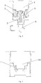
Fig. 1 is a schematic view of a water valve according to embodiments of the present disclosure; -
Fig. 2 is a sectional view of the water valve shown inFig. 1 , in which the water valve is at a state of not discharging water; -
Fig. 3 is a sectional view of the water valve shown inFig. 1 , in which the water valve is at a state of discharging water; -
Fig. 4 is a sectional view of an upper support shown inFig. 2 ; -
Fig. 5 is a sectional view of a lower support shown inFig. 2 ; -
Fig. 6 is a sectional view of a valve spool shown inFig. 2 ; and -
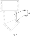
Fig. 7 is a sectional view of a water outlet pipe shown inFig. 2 ; - 1 upper support; 101 water inlet; 2 lower support; 201 water outlet; 202 vent hole; 203 snap; 3 valve spool; 301 annular groove; 302 snapping groove; 4 sealing member; 5 spring; 6 water outlet pipe; 601 first pipe segment; 602 second pipe segment.
- Reference will be made in detail to embodiments of the present disclosure. The same or similar elements and the elements having same or similar functions are denoted by like reference numerals throughout the descriptions. The embodiments described herein with reference to drawings are explanatory, illustrative, and used to generally understand the present disclosure.
- In the specification, unless specified or limited otherwise, relative terms such as "central", "longitudinal", "lateral", "front", "rear", "right", "left", "inner", "outer", "lower", "upper", "horizontal", "vertical", "above", "below", "up", "top", "bottom" as well as derivative thereof (e.g., "horizontally", "downwardly", "upwardly", etc.) should be construed to refer to the orientation as then described or as shown in the drawings under discussion. These relative terms are for convenience of description and do not require that the present disclosure be constructed or operated in a particular orientation.
- It should be noted that, terms such as "first" and "second" are used herein for purposes of description and are not intended to indicate or imply relative importance or significance or to imply the number of indicated technical features. Thus, the feature defined with "first" and "second" may comprise one or more of this feature. In the description of the present disclosure, "a plurality of' means two or more than two, unless specified otherwise.
- A water valve according to some embodiments of the present disclosure is described below with reference to
Figs. 1-7 . - As shown in
Figs. 1, 2 and3 , the water valve includes anupper support 1, alower support 2, avalve spool 3, a sealingmember 4, aspring 5, and awater outlet pipe 6. - As shown in
Figs. 1-4 , the upper support 1 is connected with a drinking device, and the upper support 1 is provided with a water inlet 101; as shown inFigs. 1, 2 ,3 and5 , the lower support 2 is connected with the upper support 1, and is movable relative to the upper support 1, the lower support 2 is provided with a water outlet 201 and a vent hole 202, and the vent hole 202 is communicated with the water outlet 201; as shown inFigs. 2 and3 , a first end of the valve spool 3 is connected with the upper support 1, a second end of the valve spool 3 is fixedly connected with the lower support 2, and the valve spool 3 is movable relative to the upper support 1, so as to switch on or off a communication between the water inlet 101 and the water outlet 201; as shown inFigs. 2 andFig. 3 , the sealing member 4 is fitted over the first end of the valve spool 3 connected with the upper support 1; as shown inFigs. 2 andFig. 3 , the spring 5 is disposed between the upper support 1 and the lower support 2; the water outlet pipe 6 is connected with the lower support 2 and communicated with the water outlet 201; when the water valve is at a state of discharging water, an interior of the water outlet pipe 6 is not communicated with atmosphere, when the water valve is at a state of not discharging water, the vent hole 202 communicates the interior of the water outlet pipe 6 with the atmosphere. - The water valve according to embodiments of the present disclosure, has a simple structure and a low cost, and is easy to be disassembled and assembled. Meanwhile, when the water valve is at the state of not discharging water, the
vent hole 202 formed in thelower support 2 communicates thewater outlet 201 with the atmosphere, so as to enable a pressure in the interior of thewater outlet pipe 6 to be equal to an atmosphere pressure, such that water remained in thewater outlet pipe 6 quickly flows out from thewater outlet pipe 6 under an action of gravity, thus keeping thewater outlet pipe 6 clean and dry, solving a problem that water drops remained in thewater outlet pipe 6 are contaminated by dust and bacterium in air, which thereby results in a contaminated drinking water, and therefore improving a market competitiveness of the device. - In an embodiment of the present disclosure, a diameter of the
water outlet pipe 6 ranges from 6mm to 15mm. Preferably, the diameter of thewater outlet pipe 6 is 10mm. - In the embodiment, under an action of water surface tension, the water remained in the pipe forms a water drop on an inner wall thereof. Relative to the
water outlet pipe 6 of a small diameter, the water drop on the inner wall of thewater outlet pipe 6 with a large diameter has a relatively small contact area with the inner wall, so an adhesive force of the water drop is small, and thus it is much easier for the water drop to slip out of the inner wall of thewater outlet pipe 6. - In an embodiment of the present disclosure, the first end of the
valve spool 3 connected with theupper support 1 is provided with anannular groove 301, and the sealingmember 4 is located in theannular groove 301. Preferably, the sealingmember 4 is configured as asilicone sealing member 4. - In the embodiment, the sealing
member 4 is mounted in theannular groove 301, thus ensuring a firm installation between the sealingmember 4 and thevalve spool 3. Under an action of thespring 5, the sealingmember 4 is fitted with theupper support 1 more closely, thus enabling the sealing between thevalve spool 3 and theupper support 1 to be much tighter. - In a specific embodiment of the present disclosure, as shown in
Fig. 5 , thelower support 2 is provided with asnap 203, and as shown inFig. 6 , thevalve spool 3 is provided with a snappinggroove 302 fitted with thesnap 203. As shown inFigs. 2 and3 , thevalve spool 3 is fixedly connected with thelower support 2 through a fit between thesnap 203 and the snappinggroove 302. - In the embodiment, in the case of meeting the requirement of use intensity, a fixed connection manner using the
snap 203 and the snappinggroove 302 provides a simple structure as well as easy assembling and disassembling, thus effectively improving a production efficiency and reducing a production and manufacturing cost. - In an embodiment of the present disclosure, the
water outlet pipe 6 includes afirst pipe segment 601 and asecond pipe segment 602, thefirst pipe segment 601 is connected with thelower support 2, and thesecond pipe segment 602 is connected with thefirst pipe segment 601 and obliquely arranged relative to thefirst pipe segment 601. Preferably, an included angle between thefirst pipe segment 601 and thesecond pipe segment 602 ranges from 30° to 60°. - In the embodiment, since the included angle exists between the
first pipe segment 601 and thesecond pipe segment 602, thesecond pipe segment 602 can extend out of the drinking device, thus facilitating getting water by a user. - In an embodiment of the present disclosure, the
water outlet pipe 6 is configured as an integrated structure formed by injection molding. - In the embodiment, the
first pipe segment 601 and thesecond pipe segment 602 are configured as the integrated structure. On one hand, a connection strength between thefirst pipe segment 601 and thesecond pipe segment 602 is increased, thus reducing a probability of fracture to occur between thefirst pipe segment 601 and thesecond pipe segment 602, and thereby enhancing use reliability of thewater outlet pipe 6. On the other hand, thewater outlet pipe 6 may be produced in batch, thus improving the production efficiency, and lowering the production and manufacturing cost. - A use process of the water valve of the present disclosure is described below in combination with
Fig. 2 andFig. 3 . - As shown in
Fig. 3 , when a drinking device is used to discharge water, thelower support 2 is moved upward to compress thespring 5, and thevalve spool 3 is moved together with thelower support 2, thus enabling thewater inlet 101 of theupper support 1 and thewater outlet 201 of thelower support 2 to be communicated with each other. As shown inFig. 2 , after getting water, the water valve is switched off and thespring 5 returns to its initial shape, so as to enable thelower support 2, thewater outlet pipe 6, thevalve spool 3 and the sealingmember 4 to move downward, so that the sealingmember 4 plugs up thewater inlet 101 of theupper support 1, and thus water cannot continue flowing out. At the same time, because of thevent hole 202 formed in thelower support 2, the pressure in the interior of thewater outlet pipe 6 is enabled to be equal to the atmosphere pressure, and thus the water drops remained in thewater outlet pipe 6 flow out rapidly under the action of gravity. - The present disclosure further provides a drinking device, including the water valve according to above embodiments of a first aspect of the present disclosure.
- The drinking device according to embodiments of the present disclosure, by adopting the water valve of the embodiments of the first aspect, solves the problem that water drops remained in the
water outlet pipe 6 are contaminated by the dust and bacterium in air, which thereby results in the contaminated drinking water, therefore improving the market competitiveness of the product. - Reference throughout this specification to "an embodiment," "some embodiments," "one embodiment", "another example," "an example," "a specific example," or "some examples," means that a particular feature, structure, material, or characteristic described in connection with the embodiment or example is included in at least one embodiment or example of the present disclosure. Thus, the appearances of the phrases such as "in some embodiments," "in one embodiment", "in an embodiment", "in another example," "in an example," "in a specific example," or "in some examples," in various places throughout this specification are not necessarily referring to the same embodiment or example of the present disclosure. Furthermore, the particular features, structures, materials, or characteristics may be combined in any suitable manner in one or more embodiments or examples within the scope of the claims.
Claims (9)
- A water valve, used for a drinking device, comprising:an upper support (1) connected with the drinking device and provided with a water inlet (101);a lower support (2) connected with the upper support, movable relative to the upper support, and provided with a water outlet (201);a valve spool (3) having a first end connected with the upper support and a second end fixedly connected with the lower support, in which the valve spool (3) is movable relative to the upper support, to switch on or off a communication between the water inlet (101) and the water outlet (201);a sealing member (4) fitted over the first end of the valve spool connected with the upper support;a spring (5) disposed between the upper support (1) and the lower support (2); anda water outlet pipe (6) connected with the lower support and communicated with the water outlet,characterized in that the lower support (2) is provided with a vent hole (202), the vent hole is communicated with the water outlet; a lower end of the water inlet (101) defines a shoulder, when the water valve is at a state of discharging water, an upper end of the water outlet (201) is received at the shoulder to switch off the communication between the vent hole (202) and the water outlet (201), such that an interior of the water outlet pipe (6) is not communicated with atmosphere; when the water valve is at a state of not discharging water, the upper end of the water outlet (201) is disengaged from the shoulder to switch on the communication between the vent hole (202) and the water outlet (201), such that the vent hole (202) communicates the interior of the water outlet pipe (6) with the atmosphere.
- The water valve according to claim 1, wherein a diameter of the water outlet pipe (6) ranges from 6mm to 15mm.
- The water valve according to claim 2, wherein the diameter of the water outlet pipe (6) is 10mm.
- The water valve according to claim 2 or 3, wherein the first end of the valve spool (3) connected with the upper support is provided with an annular groove (301), and the sealing member (4) is located in the annular groove (301).
- The water valve according to claim 4, wherein the sealing member (4) is configured as a silicone sealing member.
- The water valve according to claim 4, wherein the lower support (2) is provided with a snap (203), the valve spool (3) is provided with a snapping groove (302) configured to be fitted with the snap (203), and the valve spool (3) is fixedly connected with the lower support (2) through a fit between the snap (203) and the snapping groove (302).
- The water valve according to any one of claims 1-6, wherein the water outlet pipe (6) comprises:a first pipe segment (601) connected with the lower support (2); anda second pipe segment (602) connected with the first pipe segment (601) and obliquely arranged relative to the first pipe segment (601).
- The water valve according to claim 7, wherein an included angle between the first pipe segment (601) and the second pipe segment (602) ranges from 30° to 60°.
- A drinking device, comprising a water valve according to any one of claims 1-8.
Applications Claiming Priority (2)
| Application Number | Priority Date | Filing Date | Title |
|---|---|---|---|
| CN201410111969.6A CN103892713B (en) | 2014-03-24 | 2014-03-24 | water valve and water dispenser |
| PCT/CN2014/090622 WO2015143877A1 (en) | 2014-03-24 | 2014-11-07 | Water valve and water dispenser |
Publications (3)
| Publication Number | Publication Date |
|---|---|
| EP3123909A1 EP3123909A1 (en) | 2017-02-01 |
| EP3123909A4 EP3123909A4 (en) | 2017-12-27 |
| EP3123909B1 true EP3123909B1 (en) | 2021-04-28 |
Family
ID=50984539
Family Applications (1)
| Application Number | Title | Priority Date | Filing Date |
|---|---|---|---|
| EP14887686.5A Active EP3123909B1 (en) | 2014-03-24 | 2014-11-07 | Water valve and water dispenser |
Country Status (4)
| Country | Link |
|---|---|
| US (1) | US9943875B2 (en) |
| EP (1) | EP3123909B1 (en) |
| CN (1) | CN103892713B (en) |
| WO (1) | WO2015143877A1 (en) |
Families Citing this family (9)
| Publication number | Priority date | Publication date | Assignee | Title |
|---|---|---|---|---|
| CN103892713B (en) * | 2014-03-24 | 2017-01-11 | 合肥华凌股份有限公司 | water valve and water dispenser |
| CN104501517A (en) * | 2014-12-26 | 2015-04-08 | 合肥华凌股份有限公司 | Refrigerator and water dispenser |
| CN105877495A (en) * | 2015-01-23 | 2016-08-24 | 宁波市鄞州蓝茵工业产品设计有限公司 | Novel instant-heating type drinking water dispenser |
| CN105520643B (en) * | 2016-01-28 | 2018-09-04 | 海信容声(广东)冰箱有限公司 | A kind of reversed bay-type drinking-water switch |
| JP2020516344A (en) * | 2017-04-11 | 2020-06-11 | ソシエテ・デ・プロデュイ・ネスレ・エス・アー | Beverage preparation device provided with beverage discharging means |
| CN109431286B (en) * | 2018-11-09 | 2024-03-12 | 珠海格力电器股份有限公司 | Water tank water stopping structure and cooking utensil |
| CN110384401A (en) * | 2019-08-22 | 2019-10-29 | 杨崇坝 | It is a kind of to utilize the drip-proof office space water dispenser of principle of negative pressure |
| CN116369739B (en) * | 2022-12-28 | 2025-09-26 | 珠海格力电器股份有限公司 | Desktop water purifier |
| CN119240147A (en) * | 2024-10-10 | 2025-01-03 | 阿普塔(中国)投资有限公司 | A distributor |
Family Cites Families (22)
| Publication number | Priority date | Publication date | Assignee | Title |
|---|---|---|---|---|
| US966270A (en) * | 1909-08-20 | 1910-08-02 | S S Wenzell Machine Company | Bottle-filling machine. |
| US2504276A (en) * | 1945-12-29 | 1950-04-18 | Justrite Manufacturing Co | Gasoline dispensing container with venting means responsive to internal vapor pressure |
| US3278094A (en) * | 1966-02-07 | 1966-10-11 | Plews Oiler Inc | Pouring spout for battery fillers and the like |
| US4442873A (en) * | 1981-11-27 | 1984-04-17 | Crown Cork & Seal Company, Inc. | Container actuated counterpressure filling valve |
| US4667710A (en) * | 1986-08-14 | 1987-05-26 | Wu Ta Hsiung | Liquid pouring device |
| US5259423A (en) * | 1988-06-27 | 1993-11-09 | Link Research & Development, Inc. | Liquid flow control system |
| US5234038A (en) * | 1991-09-27 | 1993-08-10 | Briggs & Stratton Corporation | Pour spout |
| KR970078537A (en) * | 1996-05-31 | 1997-12-12 | 배순훈 | Refrigerator water supply |
| CN2886241Y (en) * | 2006-02-15 | 2007-04-04 | 于乔治 | Safety water tap |
| KR200447366Y1 (en) * | 2008-01-29 | 2010-01-20 | 문지연 | Water Saver with Automatic Air Supply Valve |
| DE102008052277B3 (en) * | 2008-10-18 | 2010-04-08 | Itw Automotive Products Gmbh | Dispenser valve assembly for a vessel |
| CN202402701U (en) * | 2011-12-08 | 2012-08-29 | 郭立秋 | Anti-freezing valve |
| CN202567825U (en) | 2012-04-17 | 2012-12-05 | 泓发乐活氏水科技服务股份有限公司 | Water outlet device of water dispenser |
| CN202812360U (en) * | 2012-08-29 | 2013-03-20 | 青岛经济技术开发区海尔热水器有限公司 | Flow regulating device, water flow sensor and gas water heater |
| CN203023564U (en) * | 2012-11-08 | 2013-06-26 | 深圳市大能节能技术有限公司 | Embedded water flow self-control water saving faucet |
| CN103291956A (en) * | 2013-05-11 | 2013-09-11 | 张君贝 | Air incoming and water draining device and water heater connecting pipeline |
| CN203468347U (en) | 2013-08-08 | 2014-03-12 | 泰州乐金电子冷机有限公司 | Water nozzle and water dispenser with the water nozzle |
| CN103697175A (en) * | 2014-01-06 | 2014-04-02 | 合肥华凌股份有限公司 | Water valve for water dispenser of refrigerator |
| CN103697176A (en) * | 2014-01-06 | 2014-04-02 | 合肥华凌股份有限公司 | Water valve for water dispenser of refrigerator |
| CN203885324U (en) * | 2014-03-24 | 2014-10-22 | 合肥华凌股份有限公司 | Water valve and water dispenser |
| CN103892713B (en) * | 2014-03-24 | 2017-01-11 | 合肥华凌股份有限公司 | water valve and water dispenser |
| CN203762901U (en) * | 2014-03-25 | 2014-08-13 | 合肥华凌股份有限公司 | Water valve and water dispenser |
-
2014
- 2014-03-24 CN CN201410111969.6A patent/CN103892713B/en active Active
- 2014-11-07 EP EP14887686.5A patent/EP3123909B1/en active Active
- 2014-11-07 WO PCT/CN2014/090622 patent/WO2015143877A1/en not_active Ceased
- 2014-11-07 US US15/128,122 patent/US9943875B2/en active Active
Non-Patent Citations (1)
| Title |
|---|
| None * |
Also Published As
| Publication number | Publication date |
|---|---|
| CN103892713A (en) | 2014-07-02 |
| US9943875B2 (en) | 2018-04-17 |
| WO2015143877A1 (en) | 2015-10-01 |
| EP3123909A1 (en) | 2017-02-01 |
| CN103892713B (en) | 2017-01-11 |
| EP3123909A4 (en) | 2017-12-27 |
| US20170095832A1 (en) | 2017-04-06 |
Similar Documents
| Publication | Publication Date | Title |
|---|---|---|
| EP3123909A1 (en) | Water valve and water dispenser | |
| US9533893B2 (en) | Faucet with built-in filter units | |
| WO2018113129A1 (en) | Showerhead capable of quickly discharging residual water | |
| CN110897507A (en) | Liquid container and insulating pot of two-way water intaking and draining | |
| CN203769031U (en) | Water spraying structure for intelligent water closet | |
| CN204459434U (en) | Integrated inductive faucet soap feeding device | |
| US10145092B2 (en) | Device for preventing backflow | |
| CN205433352U (en) | Multifunctional water fountain for preventing children from being scalded | |
| CN103644324B (en) | A kind of automatic drain valve of water heater | |
| KR101593205B1 (en) | A grass window cleaning apparatus | |
| US20160090720A1 (en) | Two-Path Water Output Device | |
| CN101956853B (en) | A delay flushing valve | |
| CN205658779U (en) | Faucet structure of refrigerator water dispenser | |
| CN204520341U (en) | Faucet assembly | |
| CN209067900U (en) | A kind of tap of adjustable water outlet area coverage | |
| WO2020201676A1 (en) | Spray head | |
| CN201420897Y (en) | Foam type constant flow water saving bubbler | |
| CN204091715U (en) | A kind of electric hot water bottle | |
| CN206631794U (en) | One kind, which is closed, stops gondola water faucet | |
| CN204114159U (en) | A kind of novel liquid discharge device | |
| CN203314850U (en) | Shower device | |
| CN101892698A (en) | Water film antifouling and wash water controlling device of shower toilet | |
| CN105919425A (en) | Water dispenser | |
| CN206483591U (en) | A kind of residual water arranges gondola water faucet soon | |
| CN105457774A (en) | An anti-drip shower head |
Legal Events
| Date | Code | Title | Description |
|---|---|---|---|
| STAA | Information on the status of an ep patent application or granted ep patent |
Free format text: STATUS: THE INTERNATIONAL PUBLICATION HAS BEEN MADE |
|
| PUAI | Public reference made under article 153(3) epc to a published international application that has entered the european phase |
Free format text: ORIGINAL CODE: 0009012 |
|
| STAA | Information on the status of an ep patent application or granted ep patent |
Free format text: STATUS: REQUEST FOR EXAMINATION WAS MADE |
|
| 17P | Request for examination filed |
Effective date: 20160915 |
|
| AK | Designated contracting states |
Kind code of ref document: A1 Designated state(s): AL AT BE BG CH CY CZ DE DK EE ES FI FR GB GR HR HU IE IS IT LI LT LU LV MC MK MT NL NO PL PT RO RS SE SI SK SM TR |
|
| AX | Request for extension of the european patent |
Extension state: BA ME |
|
| DAX | Request for extension of the european patent (deleted) | ||
| A4 | Supplementary search report drawn up and despatched |
Effective date: 20171128 |
|
| RIC1 | Information provided on ipc code assigned before grant |
Ipc: F16K 1/36 20060101ALI20171120BHEP Ipc: F16K 1/46 20060101ALI20171120BHEP Ipc: F16K 27/02 20060101ALI20171120BHEP Ipc: F16K 1/00 20060101ALI20171120BHEP Ipc: A47J 31/46 20060101AFI20171120BHEP |
|
| STAA | Information on the status of an ep patent application or granted ep patent |
Free format text: STATUS: EXAMINATION IS IN PROGRESS |
|
| 17Q | First examination report despatched |
Effective date: 20190404 |
|
| GRAP | Despatch of communication of intention to grant a patent |
Free format text: ORIGINAL CODE: EPIDOSNIGR1 |
|
| STAA | Information on the status of an ep patent application or granted ep patent |
Free format text: STATUS: GRANT OF PATENT IS INTENDED |
|
| INTG | Intention to grant announced |
Effective date: 20201119 |
|
| GRAS | Grant fee paid |
Free format text: ORIGINAL CODE: EPIDOSNIGR3 |
|
| GRAA | (expected) grant |
Free format text: ORIGINAL CODE: 0009210 |
|
| STAA | Information on the status of an ep patent application or granted ep patent |
Free format text: STATUS: THE PATENT HAS BEEN GRANTED |
|
| AK | Designated contracting states |
Kind code of ref document: B1 Designated state(s): AL AT BE BG CH CY CZ DE DK EE ES FI FR GB GR HR HU IE IS IT LI LT LU LV MC MK MT NL NO PL PT RO RS SE SI SK SM TR |
|
| REG | Reference to a national code |
Ref country code: GB Ref legal event code: FG4D |
|
| REG | Reference to a national code |
Ref country code: CH Ref legal event code: EP |
|
| REG | Reference to a national code |
Ref country code: AT Ref legal event code: REF Ref document number: 1386143 Country of ref document: AT Kind code of ref document: T Effective date: 20210515 |
|
| REG | Reference to a national code |
Ref country code: DE Ref legal event code: R096 Ref document number: 602014077081 Country of ref document: DE |
|
| REG | Reference to a national code |
Ref country code: IE Ref legal event code: FG4D |
|
| REG | Reference to a national code |
Ref country code: LT Ref legal event code: MG9D |
|
| REG | Reference to a national code |
Ref country code: AT Ref legal event code: MK05 Ref document number: 1386143 Country of ref document: AT Kind code of ref document: T Effective date: 20210428 |
|
| PG25 | Lapsed in a contracting state [announced via postgrant information from national office to epo] |
Ref country code: BG Free format text: LAPSE BECAUSE OF FAILURE TO SUBMIT A TRANSLATION OF THE DESCRIPTION OR TO PAY THE FEE WITHIN THE PRESCRIBED TIME-LIMIT Effective date: 20210728 Ref country code: AT Free format text: LAPSE BECAUSE OF FAILURE TO SUBMIT A TRANSLATION OF THE DESCRIPTION OR TO PAY THE FEE WITHIN THE PRESCRIBED TIME-LIMIT Effective date: 20210428 Ref country code: FI Free format text: LAPSE BECAUSE OF FAILURE TO SUBMIT A TRANSLATION OF THE DESCRIPTION OR TO PAY THE FEE WITHIN THE PRESCRIBED TIME-LIMIT Effective date: 20210428 Ref country code: NL Free format text: LAPSE BECAUSE OF FAILURE TO SUBMIT A TRANSLATION OF THE DESCRIPTION OR TO PAY THE FEE WITHIN THE PRESCRIBED TIME-LIMIT Effective date: 20210428 Ref country code: LT Free format text: LAPSE BECAUSE OF FAILURE TO SUBMIT A TRANSLATION OF THE DESCRIPTION OR TO PAY THE FEE WITHIN THE PRESCRIBED TIME-LIMIT Effective date: 20210428 Ref country code: HR Free format text: LAPSE BECAUSE OF FAILURE TO SUBMIT A TRANSLATION OF THE DESCRIPTION OR TO PAY THE FEE WITHIN THE PRESCRIBED TIME-LIMIT Effective date: 20210428 |
|
| PG25 | Lapsed in a contracting state [announced via postgrant information from national office to epo] |
Ref country code: IS Free format text: LAPSE BECAUSE OF FAILURE TO SUBMIT A TRANSLATION OF THE DESCRIPTION OR TO PAY THE FEE WITHIN THE PRESCRIBED TIME-LIMIT Effective date: 20210828 Ref country code: LV Free format text: LAPSE BECAUSE OF FAILURE TO SUBMIT A TRANSLATION OF THE DESCRIPTION OR TO PAY THE FEE WITHIN THE PRESCRIBED TIME-LIMIT Effective date: 20210428 Ref country code: SE Free format text: LAPSE BECAUSE OF FAILURE TO SUBMIT A TRANSLATION OF THE DESCRIPTION OR TO PAY THE FEE WITHIN THE PRESCRIBED TIME-LIMIT Effective date: 20210428 Ref country code: RS Free format text: LAPSE BECAUSE OF FAILURE TO SUBMIT A TRANSLATION OF THE DESCRIPTION OR TO PAY THE FEE WITHIN THE PRESCRIBED TIME-LIMIT Effective date: 20210428 Ref country code: NO Free format text: LAPSE BECAUSE OF FAILURE TO SUBMIT A TRANSLATION OF THE DESCRIPTION OR TO PAY THE FEE WITHIN THE PRESCRIBED TIME-LIMIT Effective date: 20210728 Ref country code: PT Free format text: LAPSE BECAUSE OF FAILURE TO SUBMIT A TRANSLATION OF THE DESCRIPTION OR TO PAY THE FEE WITHIN THE PRESCRIBED TIME-LIMIT Effective date: 20210830 Ref country code: PL Free format text: LAPSE BECAUSE OF FAILURE TO SUBMIT A TRANSLATION OF THE DESCRIPTION OR TO PAY THE FEE WITHIN THE PRESCRIBED TIME-LIMIT Effective date: 20210428 Ref country code: ES Free format text: LAPSE BECAUSE OF FAILURE TO SUBMIT A TRANSLATION OF THE DESCRIPTION OR TO PAY THE FEE WITHIN THE PRESCRIBED TIME-LIMIT Effective date: 20210428 |
|
| REG | Reference to a national code |
Ref country code: NL Ref legal event code: MP Effective date: 20210428 |
|
| PG25 | Lapsed in a contracting state [announced via postgrant information from national office to epo] |
Ref country code: DK Free format text: LAPSE BECAUSE OF FAILURE TO SUBMIT A TRANSLATION OF THE DESCRIPTION OR TO PAY THE FEE WITHIN THE PRESCRIBED TIME-LIMIT Effective date: 20210428 Ref country code: EE Free format text: LAPSE BECAUSE OF FAILURE TO SUBMIT A TRANSLATION OF THE DESCRIPTION OR TO PAY THE FEE WITHIN THE PRESCRIBED TIME-LIMIT Effective date: 20210428 Ref country code: CZ Free format text: LAPSE BECAUSE OF FAILURE TO SUBMIT A TRANSLATION OF THE DESCRIPTION OR TO PAY THE FEE WITHIN THE PRESCRIBED TIME-LIMIT Effective date: 20210428 Ref country code: SM Free format text: LAPSE BECAUSE OF FAILURE TO SUBMIT A TRANSLATION OF THE DESCRIPTION OR TO PAY THE FEE WITHIN THE PRESCRIBED TIME-LIMIT Effective date: 20210428 Ref country code: SK Free format text: LAPSE BECAUSE OF FAILURE TO SUBMIT A TRANSLATION OF THE DESCRIPTION OR TO PAY THE FEE WITHIN THE PRESCRIBED TIME-LIMIT Effective date: 20210428 Ref country code: RO Free format text: LAPSE BECAUSE OF FAILURE TO SUBMIT A TRANSLATION OF THE DESCRIPTION OR TO PAY THE FEE WITHIN THE PRESCRIBED TIME-LIMIT Effective date: 20210428 |
|
| REG | Reference to a national code |
Ref country code: DE Ref legal event code: R097 Ref document number: 602014077081 Country of ref document: DE |
|
| PLBE | No opposition filed within time limit |
Free format text: ORIGINAL CODE: 0009261 |
|
| STAA | Information on the status of an ep patent application or granted ep patent |
Free format text: STATUS: NO OPPOSITION FILED WITHIN TIME LIMIT |
|
| 26N | No opposition filed |
Effective date: 20220131 |
|
| PG25 | Lapsed in a contracting state [announced via postgrant information from national office to epo] |
Ref country code: IS Free format text: LAPSE BECAUSE OF FAILURE TO SUBMIT A TRANSLATION OF THE DESCRIPTION OR TO PAY THE FEE WITHIN THE PRESCRIBED TIME-LIMIT Effective date: 20210828 Ref country code: AL Free format text: LAPSE BECAUSE OF FAILURE TO SUBMIT A TRANSLATION OF THE DESCRIPTION OR TO PAY THE FEE WITHIN THE PRESCRIBED TIME-LIMIT Effective date: 20210428 |
|
| PG25 | Lapsed in a contracting state [announced via postgrant information from national office to epo] |
Ref country code: MC Free format text: LAPSE BECAUSE OF FAILURE TO SUBMIT A TRANSLATION OF THE DESCRIPTION OR TO PAY THE FEE WITHIN THE PRESCRIBED TIME-LIMIT Effective date: 20210428 |
|
| REG | Reference to a national code |
Ref country code: CH Ref legal event code: PL |
|
| PG25 | Lapsed in a contracting state [announced via postgrant information from national office to epo] |
Ref country code: LU Free format text: LAPSE BECAUSE OF NON-PAYMENT OF DUE FEES Effective date: 20211107 Ref country code: BE Free format text: LAPSE BECAUSE OF NON-PAYMENT OF DUE FEES Effective date: 20211130 |
|
| REG | Reference to a national code |
Ref country code: BE Ref legal event code: MM Effective date: 20211130 |
|
| PG25 | Lapsed in a contracting state [announced via postgrant information from national office to epo] |
Ref country code: IE Free format text: LAPSE BECAUSE OF NON-PAYMENT OF DUE FEES Effective date: 20211107 |
|
| PG25 | Lapsed in a contracting state [announced via postgrant information from national office to epo] |
Ref country code: HU Free format text: LAPSE BECAUSE OF FAILURE TO SUBMIT A TRANSLATION OF THE DESCRIPTION OR TO PAY THE FEE WITHIN THE PRESCRIBED TIME-LIMIT; INVALID AB INITIO Effective date: 20141107 |
|
| PG25 | Lapsed in a contracting state [announced via postgrant information from national office to epo] |
Ref country code: CY Free format text: LAPSE BECAUSE OF FAILURE TO SUBMIT A TRANSLATION OF THE DESCRIPTION OR TO PAY THE FEE WITHIN THE PRESCRIBED TIME-LIMIT Effective date: 20210428 |
|
| PG25 | Lapsed in a contracting state [announced via postgrant information from national office to epo] |
Ref country code: LI Free format text: LAPSE BECAUSE OF NON-PAYMENT OF DUE FEES Effective date: 20220630 Ref country code: GR Free format text: LAPSE BECAUSE OF FAILURE TO SUBMIT A TRANSLATION OF THE DESCRIPTION OR TO PAY THE FEE WITHIN THE PRESCRIBED TIME-LIMIT Effective date: 20210428 Ref country code: CH Free format text: LAPSE BECAUSE OF NON-PAYMENT OF DUE FEES Effective date: 20220630 |
|
| PG25 | Lapsed in a contracting state [announced via postgrant information from national office to epo] |
Ref country code: MK Free format text: LAPSE BECAUSE OF FAILURE TO SUBMIT A TRANSLATION OF THE DESCRIPTION OR TO PAY THE FEE WITHIN THE PRESCRIBED TIME-LIMIT Effective date: 20210428 |
|
| PG25 | Lapsed in a contracting state [announced via postgrant information from national office to epo] |
Ref country code: TR Free format text: LAPSE BECAUSE OF FAILURE TO SUBMIT A TRANSLATION OF THE DESCRIPTION OR TO PAY THE FEE WITHIN THE PRESCRIBED TIME-LIMIT Effective date: 20210428 |
|
| PG25 | Lapsed in a contracting state [announced via postgrant information from national office to epo] |
Ref country code: MT Free format text: LAPSE BECAUSE OF FAILURE TO SUBMIT A TRANSLATION OF THE DESCRIPTION OR TO PAY THE FEE WITHIN THE PRESCRIBED TIME-LIMIT Effective date: 20210428 |
|
| REG | Reference to a national code |
Ref country code: DE Ref legal event code: R082 Ref document number: 602014077081 Country of ref document: DE Representative=s name: MAUCHER JENKINS PATENTANWAELTE & RECHTSANWAELT, DE |
|
| PGFP | Annual fee paid to national office [announced via postgrant information from national office to epo] |
Ref country code: DE Payment date: 20251124 Year of fee payment: 12 |
|
| PGFP | Annual fee paid to national office [announced via postgrant information from national office to epo] |
Ref country code: GB Payment date: 20251126 Year of fee payment: 12 |
|
| PGFP | Annual fee paid to national office [announced via postgrant information from national office to epo] |
Ref country code: IT Payment date: 20251120 Year of fee payment: 12 |
|
| PGFP | Annual fee paid to national office [announced via postgrant information from national office to epo] |
Ref country code: FR Payment date: 20251126 Year of fee payment: 12 |