EP3123847A1 - Tilting blade of row weeder - Google Patents
Tilting blade of row weeder Download PDFInfo
- Publication number
- EP3123847A1 EP3123847A1 EP15178998.9A EP15178998A EP3123847A1 EP 3123847 A1 EP3123847 A1 EP 3123847A1 EP 15178998 A EP15178998 A EP 15178998A EP 3123847 A1 EP3123847 A1 EP 3123847A1
- Authority
- EP
- European Patent Office
- Prior art keywords
- blade
- weeder
- row
- arm
- slidable
- Prior art date
- Legal status (The legal status is an assumption and is not a legal conclusion. Google has not performed a legal analysis and makes no representation as to the accuracy of the status listed.)
- Granted
Links
Images
Classifications
-
- A—HUMAN NECESSITIES
- A01—AGRICULTURE; FORESTRY; ANIMAL HUSBANDRY; HUNTING; TRAPPING; FISHING
- A01B—SOIL WORKING IN AGRICULTURE OR FORESTRY; PARTS, DETAILS, OR ACCESSORIES OF AGRICULTURAL MACHINES OR IMPLEMENTS, IN GENERAL
- A01B39/00—Machines specially adapted for working soil on which crops are growing
- A01B39/12—Machines specially adapted for working soil on which crops are growing for special purposes, e.g. for special culture
- A01B39/18—Machines specially adapted for working soil on which crops are growing for special purposes, e.g. for special culture for weeding
Definitions
- the present invention is a tilting blade of row weeder whose function is a mechanical cutting of weeds growing between the plants in the row.
- a known and applied orchard weeder being used for crops grown in rows consists of a frame on a suspended three-point linkage of the tractor, copying wheels, a blade lever arrangement, a rod sensor, a hydraulic drive.
- the blade lever arrangement mounted to the frame suspended on three-point linkage of the tractor, receives the drive from the hydraulic cylinder enabling the swinging of the arm with the blade.
- the work of the hydraulic cylinder is controlled by the rod sensor, which meeting the trunk of the tree deflects controlling the location of the distributor slide directing the oil to the hydraulic cylinder of double-sided action. In the result there is deflected the arm with the blade from the trunk of the tree. After passing the trunk of the tree through the rod sensor there takes place the switching of the distributor slide, as the result, the hydraulic cylinder of double-sided action transfers the arm with the blade into the working position. There takes place cutting of the weeds between the trees in the row.
- the depth of the work of the blades is set by the change of location of the blade arm against the blade lever arrangement.
- the aim of the invention is to construct such a device that could eliminate the above defect, and enabled by automatic control of cutting of the weeds between the plants in the row in the in arable farming, with one blade attached to the lever arrangement.
- a tilting blade of row weeder has a mounting bracket, the extension arm, the sliding disc and the handle of the blade, the connector, and also the arm with the blade.
- the extension arm, the connector, the blade and the handle of the blade make the four-bar linkage.
- the handle of the blade is equipped with the double rotatable and slidable kinematic pair.
- the system controlling the pivoting movement of the blade is equipped with the movement speed sensor of the weeder speed, the sensor of the plant distance in the row, the controller, the electro-distributor and the hydraulic cylinder of double-sided action.
- One working unit of the tiling blade cuts the weeds between the plants from one side of the row, and the second working unit of the tilting blade cuts the weeds between the plants from the other side of the row.
- the tilting blades of row weeder is characterised by the design allowing to cut the weeds out between plants in the row when the distance between plants is not equal and at small changes of the operating speed of the weeder.
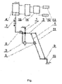
- the mounting bracket 1 is mounted to the extension arm of the weeding section of the weeder. To the bracket 1 there is mounted the extension arm 2. On the bracket 1, below the extension arm 2 there is mounted the sliding disc 3. By means of the rotatable kinematic pair he extension arm 2 there is connected the handle of the blade 4, which through the double rotatable and slidable kinematic pair 5 is connected with the slidable disc 3. The slidable disc 3 by means of the clutch 6 is connected with the piston 7 the hydraulic cylinder of double-sided action 8.
- the handle of the blade 4 below the double rotatable and slidable kinematic pair 5 is rotatably connected with the arm 9 of the blade 10.
- the arm 9 is rotatably connected with one end of the connector 11.
- the other end of the connector 11 is also rotatably connected with the extension arm 2.
- the extension arm 2, the handle of the blade 4, the arm 9 and the connector 11 make the four-bar linkage.
- the control arrangement consists of the movement speed sensor of the weeder speed 12, the sensor of the plant distance in the row 13, the controller 14, the electro-distributor 15.
- the action of the tilting blade of row weeder is the following.
- the blade makes the movement consisting of the progressive movement of the blade towards the rows of the plants and the progressive movement of the weeder in the direction in the length of the rows of the plants.
- the paths of the starting and the finishing points of the cutting edge of the blade are the curves parallel to each other marking the cutting areas of the blade.
- the arms of the blade of the weeder are distributed on both sides of the row of the plants. The shape of the curve and the cutting areas depends on the working speed (progressive) of the weeder and the speed of the movement of the blade.
- the movement parameters of the blade are selected in such a way so that the centre of the cutting edge moves independently from the uneven distribution of the plants in the row always in the direction of the centre of the distance between the neighbouring plants in the row.
- the movement of the blade towards the row of the plants is done by the movement in length of the bracket of the sliding disc, to which through the double rotatable and slidable kinematic pair is connected the handle of the blade.
- the slides of the slidable disc along the bracket are done with the hydraulic cylinder of double-sided action, which the piston is connected with the slidable disc with the help of the clutch.
- the protrusion of the piston of the hydraulic cylinder controls the control system making use of the movement speed sensor of the weeder speed, the sensor of the plant distance in the row, the controller and the electro-distributor.
- the parallel location of the blade against the ground assures its connection by means of the four-bar linkage, created by the extension arm, the connector, the arm of the blade and the handle of the blade.
Landscapes
- Life Sciences & Earth Sciences (AREA)
- Engineering & Computer Science (AREA)
- Mechanical Engineering (AREA)
- Soil Sciences (AREA)
- Environmental Sciences (AREA)
- Soil Working Implements (AREA)
- Harvester Elements (AREA)
Abstract
Description
- The present invention is a tilting blade of row weeder whose function is a mechanical cutting of weeds growing between the plants in the row.
- A known and applied orchard weeder being used for crops grown in rows consists of a frame on a suspended three-point linkage of the tractor, copying wheels, a blade lever arrangement, a rod sensor, a hydraulic drive.
- The blade lever arrangement, mounted to the frame suspended on three-point linkage of the tractor, receives the drive from the hydraulic cylinder enabling the swinging of the arm with the blade. The work of the hydraulic cylinder is controlled by the rod sensor, which meeting the trunk of the tree deflects controlling the location of the distributor slide directing the oil to the hydraulic cylinder of double-sided action. In the result there is deflected the arm with the blade from the trunk of the tree. After passing the trunk of the tree through the rod sensor there takes place the switching of the distributor slide, as the result, the hydraulic cylinder of double-sided action transfers the arm with the blade into the working position. There takes place cutting of the weeds between the trees in the row. The orchard weeder travelling between the rows, which blade cuts the weeds from one side of the row of the trees, and at the return travelling in the neighbouring row, the blade cuts the weeds from the other side of the same row of the trees.
- The depth of the work of the blades is set by the change of location of the blade arm against the blade lever arrangement.
- The aim of the invention is to construct such a device that could eliminate the above defect, and enabled by automatic control of cutting of the weeds between the plants in the row in the in arable farming, with one blade attached to the lever arrangement.
- According to the invention, a tilting blade of row weeder has a mounting bracket, the extension arm, the sliding disc and the handle of the blade, the connector, and also the arm with the blade. The extension arm, the connector, the blade and the handle of the blade make the four-bar linkage.
- The handle of the blade is equipped with the double rotatable and slidable kinematic pair. The system controlling the pivoting movement of the blade is equipped with the movement speed sensor of the weeder speed, the sensor of the plant distance in the row, the controller, the electro-distributor and the hydraulic cylinder of double-sided action. For cutting the weeds between the plants in the row of the plants there are needed two working units of the tilting blades. One working unit of the tiling blade cuts the weeds between the plants from one side of the row, and the second working unit of the tilting blade cuts the weeds between the plants from the other side of the row.
- The tilting blades of row weeder, according to the invention, is characterised by the design allowing to cut the weeds out between plants in the row when the distance between plants is not equal and at small changes of the operating speed of the weeder.
- An object of the invention is presented in the example of making in the drawing in the general outline.
- The mounting bracket 1 is mounted to the extension arm of the weeding section of the weeder. To the bracket 1 there is mounted the
extension arm 2. On the bracket 1, below theextension arm 2 there is mounted thesliding disc 3. By means of the rotatable kinematic pair heextension arm 2 there is connected the handle of theblade 4, which through the double rotatable and slidablekinematic pair 5 is connected with theslidable disc 3. Theslidable disc 3 by means of theclutch 6 is connected with thepiston 7 the hydraulic cylinder of double-sided action 8. The handle of theblade 4 below the double rotatable and slidablekinematic pair 5 is rotatably connected with thearm 9 of theblade 10. Thearm 9 is rotatably connected with one end of theconnector 11. The other end of theconnector 11 is also rotatably connected with theextension arm 2. Theextension arm 2, the handle of theblade 4, thearm 9 and theconnector 11 make the four-bar linkage. - The control arrangement consists of the movement speed sensor of the
weeder speed 12, the sensor of the plant distance in therow 13, thecontroller 14, the electro-distributor 15. - The action of the tilting blade of row weeder is the following. During cutting the weeds the blade makes the movement consisting of the progressive movement of the blade towards the rows of the plants and the progressive movement of the weeder in the direction in the length of the rows of the plants. The paths of the starting and the finishing points of the cutting edge of the blade are the curves parallel to each other marking the cutting areas of the blade. The arms of the blade of the weeder are distributed on both sides of the row of the plants. The shape of the curve and the cutting areas depends on the working speed (progressive) of the weeder and the speed of the movement of the blade. The movement parameters of the blade are selected in such a way so that the centre of the cutting edge moves independently from the uneven distribution of the plants in the row always in the direction of the centre of the distance between the neighbouring plants in the row. The movement of the blade towards the row of the plants is done by the movement in length of the bracket of the sliding disc, to which through the double rotatable and slidable kinematic pair is connected the handle of the blade. The slides of the slidable disc along the bracket are done with the hydraulic cylinder of double-sided action, which the piston is connected with the slidable disc with the help of the clutch. The protrusion of the piston of the hydraulic cylinder controls the control system making use of the movement speed sensor of the weeder speed, the sensor of the plant distance in the row, the controller and the electro-distributor. The parallel location of the blade against the ground assures its connection by means of the four-bar linkage, created by the extension arm, the connector, the arm of the blade and the handle of the blade.
Claims (1)
Priority Applications (2)
| Application Number | Priority Date | Filing Date | Title |
|---|---|---|---|
| EP15178998.9A EP3123847B1 (en) | 2015-07-30 | 2015-07-30 | Tilting blade of row weeder |
| DK15178998.9T DK3123847T3 (en) | 2015-07-30 | 2015-07-30 | RANGE OF RADIATORS |
Applications Claiming Priority (1)
| Application Number | Priority Date | Filing Date | Title |
|---|---|---|---|
| EP15178998.9A EP3123847B1 (en) | 2015-07-30 | 2015-07-30 | Tilting blade of row weeder |
Publications (2)
| Publication Number | Publication Date |
|---|---|
| EP3123847A1 true EP3123847A1 (en) | 2017-02-01 |
| EP3123847B1 EP3123847B1 (en) | 2019-05-08 |
Family
ID=54783337
Family Applications (1)
| Application Number | Title | Priority Date | Filing Date |
|---|---|---|---|
| EP15178998.9A Active EP3123847B1 (en) | 2015-07-30 | 2015-07-30 | Tilting blade of row weeder |
Country Status (2)
| Country | Link |
|---|---|
| EP (1) | EP3123847B1 (en) |
| DK (1) | DK3123847T3 (en) |
Citations (4)
| Publication number | Priority date | Publication date | Assignee | Title |
|---|---|---|---|---|
| GB854761A (en) * | 1956-03-21 | 1960-11-23 | Arthur Clive Nicholson | Improvements in steerage hoes |
| WO1991010350A1 (en) * | 1990-01-19 | 1991-07-25 | Sustainable Agricultural Machinery Developments Pty. Ltd. | Agricultural weeding apparatus |
| US5050372A (en) * | 1990-07-11 | 1991-09-24 | Heiskell Merle L | Fence row cleaner |
| WO2012094116A1 (en) * | 2011-01-07 | 2012-07-12 | Siemens Mark C | Automated machine for selective in situ manipulation of plants |
Family Cites Families (3)
| Publication number | Priority date | Publication date | Assignee | Title |
|---|---|---|---|---|
| DE19750130A1 (en) * | 1997-11-13 | 1999-05-20 | Amazonen Werke Dreyer H | Processing device for targeted processing across the row |
| CN101990796B (en) * | 2010-09-13 | 2012-07-18 | 中国农业大学 | Weeding robot system and method based on machine vision |
| CN103999582B (en) * | 2014-06-10 | 2016-01-20 | 中国农业大学 | Mechanical weeding hand between a kind of swing type seedling |
-
2015
- 2015-07-30 DK DK15178998.9T patent/DK3123847T3/en active
- 2015-07-30 EP EP15178998.9A patent/EP3123847B1/en active Active
Patent Citations (4)
| Publication number | Priority date | Publication date | Assignee | Title |
|---|---|---|---|---|
| GB854761A (en) * | 1956-03-21 | 1960-11-23 | Arthur Clive Nicholson | Improvements in steerage hoes |
| WO1991010350A1 (en) * | 1990-01-19 | 1991-07-25 | Sustainable Agricultural Machinery Developments Pty. Ltd. | Agricultural weeding apparatus |
| US5050372A (en) * | 1990-07-11 | 1991-09-24 | Heiskell Merle L | Fence row cleaner |
| WO2012094116A1 (en) * | 2011-01-07 | 2012-07-12 | Siemens Mark C | Automated machine for selective in situ manipulation of plants |
Also Published As
| Publication number | Publication date |
|---|---|
| EP3123847B1 (en) | 2019-05-08 |
| DK3123847T3 (en) | 2019-06-11 |
Similar Documents
| Publication | Publication Date | Title |
|---|---|---|
| DE102014009090B4 (en) | Agricultural device for conservation tillage | |
| RU160726U1 (en) | CULTIVATOR'S PAW | |
| US10368471B2 (en) | System for equalizing pressure on smoothing tools of a harrow | |
| CN104247606A (en) | Harvesting machine with servo control device used to improve operation tool height | |
| EP3504949A1 (en) | Working unit of the cultivator for potato ridges and cultivator with this working unit | |
| EP2361496A1 (en) | Combined, bilateral, adjustable agricultural tool platform | |
| RU190299U1 (en) | Device for protection of a rack of a cultivator paw against overhang of weeds | |
| US10448554B2 (en) | Electronic control system for adjusting smoothing tools of a harrow | |
| US2805612A (en) | Laterally shiftable power driven orchard cultivator | |
| RU2544924C1 (en) | Tool for intermittent furrowing-paraploughing | |
| CN203575027U (en) | Rotary cultivator avoiding device | |
| EP3011812B1 (en) | Device for forming dams for ridge crops | |
| EP3123847A1 (en) | Tilting blade of row weeder | |
| CN111065257A (en) | Remote stubble adjustment of plough plough | |
| KR102006021B1 (en) | Ridge apparatus mounted on agricultural management apparatus | |
| US4280563A (en) | Auxiliary shovels for agricultural implement | |
| JP2016073212A (en) | Mixing device for tea bush pruning litter and soil reduction in tea plantation and riding type tea garden management machine | |
| US3369612A (en) | Control for a power actuated tool | |
| SE529466C2 (en) | Utility | |
| BRPI1003225A2 (en) | tractor-mounted brush cutter with automatically swiveling arms | |
| US9992937B2 (en) | Pruning apparatus | |
| EP3123846A1 (en) | Active blade of row weeder | |
| US1195578A (en) | Agricultural machine | |
| EP3092888B1 (en) | Agricultural machine | |
| RU211958U1 (en) | Razor paw |
Legal Events
| Date | Code | Title | Description |
|---|---|---|---|
| PUAI | Public reference made under article 153(3) epc to a published international application that has entered the european phase |
Free format text: ORIGINAL CODE: 0009012 |
|
| STAA | Information on the status of an ep patent application or granted ep patent |
Free format text: STATUS: THE APPLICATION HAS BEEN PUBLISHED |
|
| AK | Designated contracting states |
Kind code of ref document: A1 Designated state(s): AL AT BE BG CH CY CZ DE DK EE ES FI FR GB GR HR HU IE IS IT LI LT LU LV MC MK MT NL NO PL PT RO RS SE SI SK SM TR |
|
| AX | Request for extension of the european patent |
Extension state: BA ME |
|
| RAP1 | Party data changed (applicant data changed or rights of an application transferred) |
Owner name: CNH INDUSTRIAL KUTNO SP. Z O.O. |
|
| STAA | Information on the status of an ep patent application or granted ep patent |
Free format text: STATUS: REQUEST FOR EXAMINATION WAS MADE |
|
| 17P | Request for examination filed |
Effective date: 20170728 |
|
| RBV | Designated contracting states (corrected) |
Designated state(s): AL AT BE BG CH CY CZ DE DK EE ES FI FR GB GR HR HU IE IS IT LI LT LU LV MC MK MT NL NO PL PT RO RS SE SI SK SM TR |
|
| GRAP | Despatch of communication of intention to grant a patent |
Free format text: ORIGINAL CODE: EPIDOSNIGR1 |
|
| STAA | Information on the status of an ep patent application or granted ep patent |
Free format text: STATUS: GRANT OF PATENT IS INTENDED |
|
| INTG | Intention to grant announced |
Effective date: 20190220 |
|
| GRAS | Grant fee paid |
Free format text: ORIGINAL CODE: EPIDOSNIGR3 |
|
| GRAA | (expected) grant |
Free format text: ORIGINAL CODE: 0009210 |
|
| STAA | Information on the status of an ep patent application or granted ep patent |
Free format text: STATUS: THE PATENT HAS BEEN GRANTED |
|
| AK | Designated contracting states |
Kind code of ref document: B1 Designated state(s): AL AT BE BG CH CY CZ DE DK EE ES FI FR GB GR HR HU IE IS IT LI LT LU LV MC MK MT NL NO PL PT RO RS SE SI SK SM TR |
|
| REG | Reference to a national code |
Ref country code: GB Ref legal event code: FG4D |
|
| REG | Reference to a national code |
Ref country code: CH Ref legal event code: EP Ref country code: AT Ref legal event code: REF Ref document number: 1128690 Country of ref document: AT Kind code of ref document: T Effective date: 20190515 |
|
| REG | Reference to a national code |
Ref country code: DE Ref legal event code: R096 Ref document number: 602015029689 Country of ref document: DE Ref country code: IE Ref legal event code: FG4D |
|
| REG | Reference to a national code |
Ref country code: DK Ref legal event code: T3 Effective date: 20190607 |
|
| REG | Reference to a national code |
Ref country code: NL Ref legal event code: MP Effective date: 20190508 |
|
| REG | Reference to a national code |
Ref country code: LT Ref legal event code: MG4D |
|
| PG25 | Lapsed in a contracting state [announced via postgrant information from national office to epo] |
Ref country code: NO Free format text: LAPSE BECAUSE OF FAILURE TO SUBMIT A TRANSLATION OF THE DESCRIPTION OR TO PAY THE FEE WITHIN THE PRESCRIBED TIME-LIMIT Effective date: 20190808 Ref country code: FI Free format text: LAPSE BECAUSE OF FAILURE TO SUBMIT A TRANSLATION OF THE DESCRIPTION OR TO PAY THE FEE WITHIN THE PRESCRIBED TIME-LIMIT Effective date: 20190508 Ref country code: LT Free format text: LAPSE BECAUSE OF FAILURE TO SUBMIT A TRANSLATION OF THE DESCRIPTION OR TO PAY THE FEE WITHIN THE PRESCRIBED TIME-LIMIT Effective date: 20190508 Ref country code: NL Free format text: LAPSE BECAUSE OF FAILURE TO SUBMIT A TRANSLATION OF THE DESCRIPTION OR TO PAY THE FEE WITHIN THE PRESCRIBED TIME-LIMIT Effective date: 20190508 Ref country code: PT Free format text: LAPSE BECAUSE OF FAILURE TO SUBMIT A TRANSLATION OF THE DESCRIPTION OR TO PAY THE FEE WITHIN THE PRESCRIBED TIME-LIMIT Effective date: 20190908 Ref country code: ES Free format text: LAPSE BECAUSE OF FAILURE TO SUBMIT A TRANSLATION OF THE DESCRIPTION OR TO PAY THE FEE WITHIN THE PRESCRIBED TIME-LIMIT Effective date: 20190508 Ref country code: HR Free format text: LAPSE BECAUSE OF FAILURE TO SUBMIT A TRANSLATION OF THE DESCRIPTION OR TO PAY THE FEE WITHIN THE PRESCRIBED TIME-LIMIT Effective date: 20190508 Ref country code: SE Free format text: LAPSE BECAUSE OF FAILURE TO SUBMIT A TRANSLATION OF THE DESCRIPTION OR TO PAY THE FEE WITHIN THE PRESCRIBED TIME-LIMIT Effective date: 20190508 Ref country code: AL Free format text: LAPSE BECAUSE OF FAILURE TO SUBMIT A TRANSLATION OF THE DESCRIPTION OR TO PAY THE FEE WITHIN THE PRESCRIBED TIME-LIMIT Effective date: 20190508 |
|
| PG25 | Lapsed in a contracting state [announced via postgrant information from national office to epo] |
Ref country code: GR Free format text: LAPSE BECAUSE OF FAILURE TO SUBMIT A TRANSLATION OF THE DESCRIPTION OR TO PAY THE FEE WITHIN THE PRESCRIBED TIME-LIMIT Effective date: 20190809 Ref country code: RS Free format text: LAPSE BECAUSE OF FAILURE TO SUBMIT A TRANSLATION OF THE DESCRIPTION OR TO PAY THE FEE WITHIN THE PRESCRIBED TIME-LIMIT Effective date: 20190508 Ref country code: LV Free format text: LAPSE BECAUSE OF FAILURE TO SUBMIT A TRANSLATION OF THE DESCRIPTION OR TO PAY THE FEE WITHIN THE PRESCRIBED TIME-LIMIT Effective date: 20190508 Ref country code: BG Free format text: LAPSE BECAUSE OF FAILURE TO SUBMIT A TRANSLATION OF THE DESCRIPTION OR TO PAY THE FEE WITHIN THE PRESCRIBED TIME-LIMIT Effective date: 20190808 |
|
| REG | Reference to a national code |
Ref country code: AT Ref legal event code: MK05 Ref document number: 1128690 Country of ref document: AT Kind code of ref document: T Effective date: 20190508 |
|
| PG25 | Lapsed in a contracting state [announced via postgrant information from national office to epo] |
Ref country code: SK Free format text: LAPSE BECAUSE OF FAILURE TO SUBMIT A TRANSLATION OF THE DESCRIPTION OR TO PAY THE FEE WITHIN THE PRESCRIBED TIME-LIMIT Effective date: 20190508 Ref country code: RO Free format text: LAPSE BECAUSE OF FAILURE TO SUBMIT A TRANSLATION OF THE DESCRIPTION OR TO PAY THE FEE WITHIN THE PRESCRIBED TIME-LIMIT Effective date: 20190508 Ref country code: CZ Free format text: LAPSE BECAUSE OF FAILURE TO SUBMIT A TRANSLATION OF THE DESCRIPTION OR TO PAY THE FEE WITHIN THE PRESCRIBED TIME-LIMIT Effective date: 20190508 Ref country code: AT Free format text: LAPSE BECAUSE OF FAILURE TO SUBMIT A TRANSLATION OF THE DESCRIPTION OR TO PAY THE FEE WITHIN THE PRESCRIBED TIME-LIMIT Effective date: 20190508 Ref country code: EE Free format text: LAPSE BECAUSE OF FAILURE TO SUBMIT A TRANSLATION OF THE DESCRIPTION OR TO PAY THE FEE WITHIN THE PRESCRIBED TIME-LIMIT Effective date: 20190508 |
|
| REG | Reference to a national code |
Ref country code: DE Ref legal event code: R097 Ref document number: 602015029689 Country of ref document: DE |
|
| PG25 | Lapsed in a contracting state [announced via postgrant information from national office to epo] |
Ref country code: SM Free format text: LAPSE BECAUSE OF FAILURE TO SUBMIT A TRANSLATION OF THE DESCRIPTION OR TO PAY THE FEE WITHIN THE PRESCRIBED TIME-LIMIT Effective date: 20190508 Ref country code: MC Free format text: LAPSE BECAUSE OF FAILURE TO SUBMIT A TRANSLATION OF THE DESCRIPTION OR TO PAY THE FEE WITHIN THE PRESCRIBED TIME-LIMIT Effective date: 20190508 |
|
| REG | Reference to a national code |
Ref country code: CH Ref legal event code: PL |
|
| PLBE | No opposition filed within time limit |
Free format text: ORIGINAL CODE: 0009261 |
|
| STAA | Information on the status of an ep patent application or granted ep patent |
Free format text: STATUS: NO OPPOSITION FILED WITHIN TIME LIMIT |
|
| PG25 | Lapsed in a contracting state [announced via postgrant information from national office to epo] |
Ref country code: TR Free format text: LAPSE BECAUSE OF FAILURE TO SUBMIT A TRANSLATION OF THE DESCRIPTION OR TO PAY THE FEE WITHIN THE PRESCRIBED TIME-LIMIT Effective date: 20190508 |
|
| 26N | No opposition filed |
Effective date: 20200211 |
|
| REG | Reference to a national code |
Ref country code: BE Ref legal event code: MM Effective date: 20190731 |
|
| PG25 | Lapsed in a contracting state [announced via postgrant information from national office to epo] |
Ref country code: PL Free format text: LAPSE BECAUSE OF FAILURE TO SUBMIT A TRANSLATION OF THE DESCRIPTION OR TO PAY THE FEE WITHIN THE PRESCRIBED TIME-LIMIT Effective date: 20190508 |
|
| PG25 | Lapsed in a contracting state [announced via postgrant information from national office to epo] |
Ref country code: LI Free format text: LAPSE BECAUSE OF NON-PAYMENT OF DUE FEES Effective date: 20190731 Ref country code: LU Free format text: LAPSE BECAUSE OF NON-PAYMENT OF DUE FEES Effective date: 20190730 Ref country code: BE Free format text: LAPSE BECAUSE OF NON-PAYMENT OF DUE FEES Effective date: 20190731 Ref country code: CH Free format text: LAPSE BECAUSE OF NON-PAYMENT OF DUE FEES Effective date: 20190731 Ref country code: SI Free format text: LAPSE BECAUSE OF FAILURE TO SUBMIT A TRANSLATION OF THE DESCRIPTION OR TO PAY THE FEE WITHIN THE PRESCRIBED TIME-LIMIT Effective date: 20190508 |
|
| PG25 | Lapsed in a contracting state [announced via postgrant information from national office to epo] |
Ref country code: IE Free format text: LAPSE BECAUSE OF NON-PAYMENT OF DUE FEES Effective date: 20190730 |
|
| PG25 | Lapsed in a contracting state [announced via postgrant information from national office to epo] |
Ref country code: CY Free format text: LAPSE BECAUSE OF FAILURE TO SUBMIT A TRANSLATION OF THE DESCRIPTION OR TO PAY THE FEE WITHIN THE PRESCRIBED TIME-LIMIT Effective date: 20190508 |
|
| PG25 | Lapsed in a contracting state [announced via postgrant information from national office to epo] |
Ref country code: IS Free format text: LAPSE BECAUSE OF FAILURE TO SUBMIT A TRANSLATION OF THE DESCRIPTION OR TO PAY THE FEE WITHIN THE PRESCRIBED TIME-LIMIT Effective date: 20190908 |
|
| PG25 | Lapsed in a contracting state [announced via postgrant information from national office to epo] |
Ref country code: HU Free format text: LAPSE BECAUSE OF FAILURE TO SUBMIT A TRANSLATION OF THE DESCRIPTION OR TO PAY THE FEE WITHIN THE PRESCRIBED TIME-LIMIT; INVALID AB INITIO Effective date: 20150730 Ref country code: MT Free format text: LAPSE BECAUSE OF FAILURE TO SUBMIT A TRANSLATION OF THE DESCRIPTION OR TO PAY THE FEE WITHIN THE PRESCRIBED TIME-LIMIT Effective date: 20190508 |
|
| PG25 | Lapsed in a contracting state [announced via postgrant information from national office to epo] |
Ref country code: MK Free format text: LAPSE BECAUSE OF FAILURE TO SUBMIT A TRANSLATION OF THE DESCRIPTION OR TO PAY THE FEE WITHIN THE PRESCRIBED TIME-LIMIT Effective date: 20190508 |
|
| PGFP | Annual fee paid to national office [announced via postgrant information from national office to epo] |
Ref country code: DK Payment date: 20250725 Year of fee payment: 11 Ref country code: DE Payment date: 20250728 Year of fee payment: 11 |
|
| PGFP | Annual fee paid to national office [announced via postgrant information from national office to epo] |
Ref country code: IT Payment date: 20250721 Year of fee payment: 11 |
|
| PGFP | Annual fee paid to national office [announced via postgrant information from national office to epo] |
Ref country code: GB Payment date: 20250722 Year of fee payment: 11 |
|
| PGFP | Annual fee paid to national office [announced via postgrant information from national office to epo] |
Ref country code: FR Payment date: 20250725 Year of fee payment: 11 |