EP3122404B1 - Subcutaneous infusion device for injecting medicinal substances - Google Patents
Subcutaneous infusion device for injecting medicinal substances Download PDFInfo
- Publication number
- EP3122404B1 EP3122404B1 EP15715591.2A EP15715591A EP3122404B1 EP 3122404 B1 EP3122404 B1 EP 3122404B1 EP 15715591 A EP15715591 A EP 15715591A EP 3122404 B1 EP3122404 B1 EP 3122404B1
- Authority
- EP
- European Patent Office
- Prior art keywords
- needle
- wing
- delivery device
- hub
- ribs
- Prior art date
- Legal status (The legal status is an assumption and is not a legal conclusion. Google has not performed a legal analysis and makes no representation as to the accuracy of the status listed.)
- Active
Links
Images


Classifications
-
- A—HUMAN NECESSITIES
- A61—MEDICAL OR VETERINARY SCIENCE; HYGIENE
- A61M—DEVICES FOR INTRODUCING MEDIA INTO, OR ONTO, THE BODY; DEVICES FOR TRANSDUCING BODY MEDIA OR FOR TAKING MEDIA FROM THE BODY; DEVICES FOR PRODUCING OR ENDING SLEEP OR STUPOR
- A61M5/00—Devices for bringing media into the body in a subcutaneous, intra-vascular or intramuscular way; Accessories therefor, e.g. filling or cleaning devices, arm-rests
- A61M5/14—Infusion devices, e.g. infusing by gravity; Blood infusion; Accessories therefor
-
- A—HUMAN NECESSITIES
- A61—MEDICAL OR VETERINARY SCIENCE; HYGIENE
- A61M—DEVICES FOR INTRODUCING MEDIA INTO, OR ONTO, THE BODY; DEVICES FOR TRANSDUCING BODY MEDIA OR FOR TAKING MEDIA FROM THE BODY; DEVICES FOR PRODUCING OR ENDING SLEEP OR STUPOR
- A61M39/00—Tubes, tube connectors, tube couplings, valves, access sites or the like, specially adapted for medical use
- A61M39/20—Closure caps or plugs for connectors or open ends of tubes
-
- A—HUMAN NECESSITIES
- A61—MEDICAL OR VETERINARY SCIENCE; HYGIENE
- A61M—DEVICES FOR INTRODUCING MEDIA INTO, OR ONTO, THE BODY; DEVICES FOR TRANSDUCING BODY MEDIA OR FOR TAKING MEDIA FROM THE BODY; DEVICES FOR PRODUCING OR ENDING SLEEP OR STUPOR
- A61M39/00—Tubes, tube connectors, tube couplings, valves, access sites or the like, specially adapted for medical use
- A61M39/22—Valves or arrangement of valves
- A61M39/28—Clamping means for squeezing flexible tubes, e.g. roller clamps
-
- A—HUMAN NECESSITIES
- A61—MEDICAL OR VETERINARY SCIENCE; HYGIENE
- A61M—DEVICES FOR INTRODUCING MEDIA INTO, OR ONTO, THE BODY; DEVICES FOR TRANSDUCING BODY MEDIA OR FOR TAKING MEDIA FROM THE BODY; DEVICES FOR PRODUCING OR ENDING SLEEP OR STUPOR
- A61M5/00—Devices for bringing media into the body in a subcutaneous, intra-vascular or intramuscular way; Accessories therefor, e.g. filling or cleaning devices, arm-rests
- A61M5/14—Infusion devices, e.g. infusing by gravity; Blood infusion; Accessories therefor
- A61M5/158—Needles for infusions; Accessories therefor, e.g. for inserting infusion needles, or for holding them on the body
-
- A—HUMAN NECESSITIES
- A61—MEDICAL OR VETERINARY SCIENCE; HYGIENE
- A61M—DEVICES FOR INTRODUCING MEDIA INTO, OR ONTO, THE BODY; DEVICES FOR TRANSDUCING BODY MEDIA OR FOR TAKING MEDIA FROM THE BODY; DEVICES FOR PRODUCING OR ENDING SLEEP OR STUPOR
- A61M5/00—Devices for bringing media into the body in a subcutaneous, intra-vascular or intramuscular way; Accessories therefor, e.g. filling or cleaning devices, arm-rests
- A61M5/178—Syringes
-
- A—HUMAN NECESSITIES
- A61—MEDICAL OR VETERINARY SCIENCE; HYGIENE
- A61M—DEVICES FOR INTRODUCING MEDIA INTO, OR ONTO, THE BODY; DEVICES FOR TRANSDUCING BODY MEDIA OR FOR TAKING MEDIA FROM THE BODY; DEVICES FOR PRODUCING OR ENDING SLEEP OR STUPOR
- A61M5/00—Devices for bringing media into the body in a subcutaneous, intra-vascular or intramuscular way; Accessories therefor, e.g. filling or cleaning devices, arm-rests
- A61M5/178—Syringes
- A61M5/31—Details
- A61M5/32—Needles; Details of needles pertaining to their connection with syringe or hub; Accessories for bringing the needle into, or holding the needle on, the body; Devices for protection of needles
- A61M5/3202—Devices for protection of the needle before use, e.g. caps
-
- A—HUMAN NECESSITIES
- A61—MEDICAL OR VETERINARY SCIENCE; HYGIENE
- A61M—DEVICES FOR INTRODUCING MEDIA INTO, OR ONTO, THE BODY; DEVICES FOR TRANSDUCING BODY MEDIA OR FOR TAKING MEDIA FROM THE BODY; DEVICES FOR PRODUCING OR ENDING SLEEP OR STUPOR
- A61M5/00—Devices for bringing media into the body in a subcutaneous, intra-vascular or intramuscular way; Accessories therefor, e.g. filling or cleaning devices, arm-rests
- A61M5/178—Syringes
- A61M5/31—Details
- A61M5/32—Needles; Details of needles pertaining to their connection with syringe or hub; Accessories for bringing the needle into, or holding the needle on, the body; Devices for protection of needles
- A61M5/3205—Apparatus for removing or disposing of used needles or syringes, e.g. containers; Means for protection against accidental injuries from used needles
- A61M5/321—Means for protection against accidental injuries by used needles
- A61M5/3243—Means for protection against accidental injuries by used needles being axially-extensible, e.g. protective sleeves coaxially slidable on the syringe barrel
-
- A—HUMAN NECESSITIES
- A61—MEDICAL OR VETERINARY SCIENCE; HYGIENE
- A61M—DEVICES FOR INTRODUCING MEDIA INTO, OR ONTO, THE BODY; DEVICES FOR TRANSDUCING BODY MEDIA OR FOR TAKING MEDIA FROM THE BODY; DEVICES FOR PRODUCING OR ENDING SLEEP OR STUPOR
- A61M5/00—Devices for bringing media into the body in a subcutaneous, intra-vascular or intramuscular way; Accessories therefor, e.g. filling or cleaning devices, arm-rests
- A61M5/178—Syringes
- A61M5/31—Details
- A61M5/32—Needles; Details of needles pertaining to their connection with syringe or hub; Accessories for bringing the needle into, or holding the needle on, the body; Devices for protection of needles
- A61M5/3205—Apparatus for removing or disposing of used needles or syringes, e.g. containers; Means for protection against accidental injuries from used needles
- A61M5/321—Means for protection against accidental injuries by used needles
- A61M5/3243—Means for protection against accidental injuries by used needles being axially-extensible, e.g. protective sleeves coaxially slidable on the syringe barrel
- A61M5/3275—Means for protection against accidental injuries by used needles being axially-extensible, e.g. protective sleeves coaxially slidable on the syringe barrel being connected to the needle hub or syringe by radially deflectable members, e.g. longitudinal slats, cords or bands
-
- A—HUMAN NECESSITIES
- A61—MEDICAL OR VETERINARY SCIENCE; HYGIENE
- A61M—DEVICES FOR INTRODUCING MEDIA INTO, OR ONTO, THE BODY; DEVICES FOR TRANSDUCING BODY MEDIA OR FOR TAKING MEDIA FROM THE BODY; DEVICES FOR PRODUCING OR ENDING SLEEP OR STUPOR
- A61M5/00—Devices for bringing media into the body in a subcutaneous, intra-vascular or intramuscular way; Accessories therefor, e.g. filling or cleaning devices, arm-rests
- A61M5/14—Infusion devices, e.g. infusing by gravity; Blood infusion; Accessories therefor
- A61M5/158—Needles for infusions; Accessories therefor, e.g. for inserting infusion needles, or for holding them on the body
- A61M2005/1581—Right-angle needle-type devices
-
- A—HUMAN NECESSITIES
- A61—MEDICAL OR VETERINARY SCIENCE; HYGIENE
- A61M—DEVICES FOR INTRODUCING MEDIA INTO, OR ONTO, THE BODY; DEVICES FOR TRANSDUCING BODY MEDIA OR FOR TAKING MEDIA FROM THE BODY; DEVICES FOR PRODUCING OR ENDING SLEEP OR STUPOR
- A61M5/00—Devices for bringing media into the body in a subcutaneous, intra-vascular or intramuscular way; Accessories therefor, e.g. filling or cleaning devices, arm-rests
- A61M5/14—Infusion devices, e.g. infusing by gravity; Blood infusion; Accessories therefor
- A61M5/158—Needles for infusions; Accessories therefor, e.g. for inserting infusion needles, or for holding them on the body
- A61M2005/1583—Needle extractors
-
- A—HUMAN NECESSITIES
- A61—MEDICAL OR VETERINARY SCIENCE; HYGIENE
- A61M—DEVICES FOR INTRODUCING MEDIA INTO, OR ONTO, THE BODY; DEVICES FOR TRANSDUCING BODY MEDIA OR FOR TAKING MEDIA FROM THE BODY; DEVICES FOR PRODUCING OR ENDING SLEEP OR STUPOR
- A61M5/00—Devices for bringing media into the body in a subcutaneous, intra-vascular or intramuscular way; Accessories therefor, e.g. filling or cleaning devices, arm-rests
- A61M5/14—Infusion devices, e.g. infusing by gravity; Blood infusion; Accessories therefor
- A61M5/158—Needles for infusions; Accessories therefor, e.g. for inserting infusion needles, or for holding them on the body
- A61M2005/1586—Holding accessories for holding infusion needles on the body
-
- A—HUMAN NECESSITIES
- A61—MEDICAL OR VETERINARY SCIENCE; HYGIENE
- A61M—DEVICES FOR INTRODUCING MEDIA INTO, OR ONTO, THE BODY; DEVICES FOR TRANSDUCING BODY MEDIA OR FOR TAKING MEDIA FROM THE BODY; DEVICES FOR PRODUCING OR ENDING SLEEP OR STUPOR
- A61M5/00—Devices for bringing media into the body in a subcutaneous, intra-vascular or intramuscular way; Accessories therefor, e.g. filling or cleaning devices, arm-rests
- A61M5/14—Infusion devices, e.g. infusing by gravity; Blood infusion; Accessories therefor
- A61M5/158—Needles for infusions; Accessories therefor, e.g. for inserting infusion needles, or for holding them on the body
- A61M2005/1587—Needles for infusions; Accessories therefor, e.g. for inserting infusion needles, or for holding them on the body suitable for being connected to an infusion line after insertion into a patient
Definitions
- the present disclosure generally relates to devices for injecting medicinal substances, and more particularly relates to a medical fluid delivery device for subcutaneously administering viscous liquid medicines into the body of a user.
- Subcutaneous infusion devices are well known in the medical arts for use in the administration of a selected medicinal substance to a desired infusion site located underneath the skin of a patient or user.
- a tubular cannula or catheter that is supported by and protrudes from a hub for receiving the medicinal substance via a delivery tubing.
- the hub typically includes a small needle that is inserted just under the surface of the skin, and remains in place for up to several days.
- such infusion devices provide an alternative to intravenous delivery of medicines and allow the medicinal substance to be administered through a layer of skin immediately below the dermis and epidermis.
- such use of the subcutaneous infusion devices decreases the number of times the patient must have an injection to receive frequently administered medicines.
- medicines are an effective and convenient way to administer medicinal substances without having to impose multiple injections on the patient.
- Foldable gripping wings are typically attached to the hub for securely holding the needle when inserting the needle straight into the desired infusion site at a 90 degree angle relative to the skin surface. Specifically, the wings are folded back away from the needle and pinched together between two fingers. At times, the folded wings slide against each other during the insertion step, making the insertion of the needle rather challenging. Further, if the needle is made of a smaller diameter, the needle is not supported firmly and causes it to break during use.
- US3640275 discloses an intravenous needle assembly for administering medication into a patient comprising a cannula having a hub portion from the opposite sides of which extend a pair of hub wing sections.
- the hub wing sections are adapted to flex in either direction around said hub into abutting contact with one another to form a gripping handle for holding the cannula while it is being inserted into the vein of the patient.
- US2006/047252 discloses a winged angled needle assembly having a hub to which a proximal end portion of an angled needle having a sharpened tip portion is joined and a pair of wings attached to both sides of the hub.
- the assembly further includes a fixing member attached so as to support the wings and an extensible, contractible needle guard disposed between the hub and the fixing member so as to connect these two members.
- WO2007/137339 discloses a Huber needle assembly having a base with hinged guide members about a needle aperture.
- a needle assembly has a Huber needle mounted between two hinged wings.
- the guide members are movable between a parallel arrangement in which the needle may move vertically between the guide members and a horizontal arrangement in which the needle is locked in the in-use position.
- US3538915 discloses an infusion device and method, the device including an infusion needle received by and cemented in fixed relation to a one-piece needle-holding member or inserter which has been folded as separate halves about one end of the needle and remains in the folded state when the cement or bonding agent has cured.
- a medical needle assembly includes a hub portion and a pair of outwardly extending wings.
- the hub portion may have a raised orientation member, with the wings being foldable to overlay the raised orientation member and contact the raised orientation member and each other.
- the hub portion may have an anti-rotation member adapted to cooperate with the wings to limit rotation of the wings with respect to the hub portion.
- the present disclosure is directed to a medical fluid delivery device for subcutaneously administering viscous liquid medicines into the body of a user or patient.
- the present infusion device is designed to reduce a pressure drop (or flow resistance) that occurs during the delivery step of the viscous liquid or solution into a subcutaneous space of the user's skin.
- the present infusion device delivers the viscous liquid at a higher flow rate than the conventional devices due to the geometry of a hub and a needle.
- One aspect of the present infusion device is that low flow resistance is achieved for high viscosity liquids (e.g., 3-20 cP) in flow rates ranging 40 to 400 ml/hr (or milliliter/hour) during subcutaneous delivery.
- a 24G (or gauge) needle having a thin tubular wall is provided for accommodating the viscous liquid, and a mid- region of the needle is slightly bent at a predetermined radius of curvature, such that the mid-region surrounds a support region located at an outer end of the hub.
- the present infusion device provides secure placement of the needle that reduces disturbance to the desired infusion site, and enhances comfort during infusion.
- a plurality of substantially diagonally disposed ribs is provided on a bottom side of the hub for preventing unwanted movement of the hub while worn by the user. More specifically, the diagonal bottom ribs are angled in such a manner that a forward movement toward the sharp end of the needle is prevented while a backward movement away from the sharp end of the needle is allowed.
- the diagonal pattern also stabilizes the hub for lateral disturbances after installation of the needle. This arrangement reduces shear and/or normal stress on the bent portion of the needle.
- a medical delivery device for delivering a medicinal substance into a user's body according to claim 1.
- Embodiments of the invention are defined in the dependent claims.
- the present disclosure is directed to a medical fluid delivery device for subcutaneously administering viscous liquid medicines into the body of a user or patient.
- the present infusion device is designed to reduce a pressure drop (or flow resistance) that occurs during the delivery step of the viscous liquid or solution into a subcutaneous space of the user's skin.
- the present infusion device delivers the viscous liquid at a higher flow rate than the conventional devices due to the geometry of a hub and a needle.
- an infusion device in which low flow resistance is achieved for high viscosity liquids (e.g., 3-20 cP) in flow rates ranging 40 to 400 ml/hr (or milliliter/hour) during subcutaneous delivery.
- a 24G (or gauge) needle having a thin tubular wall is provided for accommodating the viscous liquid, and a mid-region of the needle is slightly bent at a predetermined radius of curvature, such that the mid-region surrounds a support region located at an outer end of the hub.
- the present infusion device provides secure placement of the needle that reduces disturbance to the desired infusion site, and enhances comfort during infusion.
- a plurality of substantially diagonally disposed ribs is provided on a bottom side of the hub for preventing unwanted movement of the hub while worn by the user. More specifically, the diagonal bottom ribs are angled in such a manner that a forward movement toward the sharp end of the needle is prevented while a backward movement away from the sharp end of the needle is allowed.
- the diagonal pattern also stabilizes the hub for lateral disturbances after installation of the needle. This arrangement reduces shear and/or normal stress on the bent portion of the needle.
- a top side of the hub includes at least two ribs, each one of which is respectively located on a left wing and a right wing of the hub.
- Each rib is asymmetrically disposed on the wings, such that when the wings are folded back away from the needle and pinched together, the two ribs prevent twisting and/or sliding of the wings relative to each other during an insertion of the needle into the skin. Accordingly, the needle remains stable and straight during the insertion, preventing a breakage of the needle due to undesirable movement of the wings.
- the present subcutaneous infusion device is generally designated 10 and is designed for subcutaneously delivering a medicinal substance below the dermis and epidermis.
- An exemplary medicinal substance may include nutritional products and Chinese herbal medicinal products.
- the device 10 is disposable. Included in the device 10 is a luer cap 12 configured for receiving the liquid at one end, and at an opposite end, is attached to a female luer connector 14 using complementary helically threaded portions for threadably fastening the cap and connector together.
- a flexible elongated tube 16 is attached at one end to the female luer connector 14, and at an opposite end to a foldable hub 18 having a left or first wing 20 and a right or second wing 22.
- An exemplary length of the tube 16 is approximately 61 cm (24 inches), but it is also contemplated that any length of tube can be utilized to suit different applications.
- Regulating a flow of the viscous liquid medicine in the tube 16 is achieved by transversely adjusting a slide clamp 24 relative to a longitudinal axis of the tube.
- a movable release slot 26 is provided in a center of the slide clamp 24 such that the clamp can transition between an occluding position and a non-occluding position by selectively sliding the release slot relative to the tube 16.
- the winged hub 18 is molded, as by injection molding or the like, such that the hub and its connecting elements are integrally formed.
- the hub 18 is attachable to the connecting elements by chemical adhesives, solvent boding, ultrasonic welding or other conventional fastening techniques. More specifically, the hub 18 is attached at one end to the tube 16, and at an opposite end to a needle 28, which is slidably fitted into and safeguarded by a needle protector 30 when not in use. It is contemplated that after the hub 18 is molded, the needle 28 is assembled onto the hub 18 using an adhesive. Alternatively, the hub 18 may be over-molded over the needle 28.
- An exemplary needle size is approximately 24G for ensuring comfort during infusion, and an exemplary needle length may be one of 6, 9, or 12 mm (or millimeter) depending on an application.
- the needle 28 has a thin tubular wall for accommodating the viscous liquid medicine.
- each of the foldable left and right wings 20, 22 of the hub has at least one top rib 32, 34 extending along an entire longitudinal length of a corresponding wing.
- Each top rib 32, 34 is disposed on an upper surface 36 of the corresponding wing 20, 22, such that when the wings are folded, the top ribs 32, 34 are directly in contact with the upper surface 36 of a corresponding opposite wing.
- the top rib 32 disposed on the left wing 20 engages the upper surface 36 of the right wing 22, and conversely the top rib 34 disposed on the right wing 22 engages the upper surface 36 of the left wing 20.
- a left or first top rib 32 is asymmetrically disposed from a right or second top rib 34 such that the first top rib 32 is juxtaposed with the second top rib 34 when the wings 20, 22 are folded back away from the needle 28 and pinched together ( FIG. 5 ). More specifically, the first top rib 32 is spaced in parallel from an elongated center section 38 of the hub 18 at a first predetermined distance D A ( FIG. 1 ), but the second top rib 34 is spaced in parallel from the center section at a second predetermined distance D B ( FIG. 1 ), where the first distance D A is different from the second distance D B .
- the first distance D A is longer than the second distance D B , and the first rib 32 goes over the second rib 34 such that the ribs 32, 34 are adjacently positioned with each other when the wings 20, 22 are folded back.
- this particular configuration of the top ribs 32, 34 prevents the wings 20, 22 from twisting or sliding relative to each other, thereby reducing the risk of breakage of the needle 28 during the insertion of the needle into the skin.
- a first insertion opening 40 at a first end of the center section 38 is configured for accommodating insertion of the needle 28, and a second insertion opening 42 at a second opposite end of the center section in fluid communication with the tube 16 is configured for accommodating insertion of the tube.
- the tube 16 is inserted into the first insertion opening 40 approximately half a length of the center section 38 to reduce a total length of the needle 28 ( FIG. 2 ).
- Both openings 40, 42 provide a passage way for the delivery of the liquid medicine.
- This passage way provides low flow resistance for high viscosity liquids (e.g., 3-20 cP) in flow rates ranging 40 to 400 ml/hr during subcutaneous delivery without dropping a fluid pressure more than 68.9 kPa (10 psi or pounds per square inch).
- an exemplary 24G stainless needle 28 having the thin tubular wall is configured for accommodating the viscous liquid medicine, and a mid-region 44 of the needle 28 is slightly bent at a predetermined radius of curvature (e.g., 3.175 mm (0.125”) typically and not less than 1.524 mm (0.060") or more than 5.08 mm (0.200”)), such that the mid-region of the needle surrounds a support region 46 located at or near the first insertion opening 40 of the center section 38.
- a predetermined radius of curvature e.g., 3.175 mm (0.125” typically and not less than 1.524 mm (0.060”) or more than 5.08 mm (0.200”
- the mid-region 44 of the needle 28 is bent gradually at an angle of 45 to 90 degrees (nominally close to 90 degrees), such that the support region 46 buttresses against the bent mid-region of the needle.
- a sharp end of the needle 28 extends outwardly from the first insertion opening 40 of the center section 38 so that the sharp end of the needle is disposed transverse to a longitudinal axis of the center section. Consequently, the support region 46 reduces the risk of needle breakage, and provides integrated support for the bent mid-region 44 not only during the insertion of the needle 28 into the skin but also while being attached to the user's body.
- a plurality of substantially diagonally disposed bottom ribs 48a, 48b is provided on a lower or bottom surface 50 of each wing 20, 22 for preventing unwanted movement of the hub 18 during use. It is preferred that the bottom ribs 48a, 48b are generally evenly spaced in parallel, and extend along a full diagonal length of a corresponding wing 20, 22.
- the bottom ribs 48a, 48b are angled or slanted in such a manner that a forward movement toward the sharp end of the needle 28 is prevented, while a backward movement away from the sharp end of the needle is allowed. This particular arrangement reduces shear and/or normal stress on the bent mid-region 44 of the needle 28 during use.
- both the first and second wings 20, 22 of the hub 18 have the bottom ribs 48a, 48b positioned on the lower surface 50 at an angle of approximately 45 degrees relative to the longitudinal axis of the center section 38.
- An important aspect of the ribs 48a, 48b is, however, that each bottom rib 48a disposed on the lower surface 50 of the first wing 20 is inclined or sloped upwardly from a left side of the first wing to a right side of the first wing toward the center section 38.
- each bottom rib 48b disposed on the lower surface 50 of the second wing 22 is declined or sloped downwardly from a left side of the second wing adjacent the center section 38 to a right side of the second wing.
- the bottom ribs 48a, 48b are constructed and arranged in a chevron or herringbone pattern, thereby preventing unwanted movement of the hub 18 while being attached to the user's body.
- ribs 48a, 48b prevents slippage of the hub 18 from the skin during use. While diagonally arranged ribs 48a, 48b are shown for illustration purposes, any type of knurling or textured ribs, ridges, grooves, or bumps are contemplated for disposition as a friction formation on the lower surface 50 of the wings 20, 22 for enhancing friction in this manner. Further, the angular orientation and/or spacing of the ribs 48a, 48b is variable to suit the situation.
- FIGs. 5-7 an exemplary use of the present infusion device is illustrated in greater detail.
- the user folds the wings 20, 22 back away from the needle 28 and pinches the wings together between two fingers. Then, the user subsequently removes the needle protector 30 from the needle 28, and discards the protector ( FIG. 5 ).
- the user pinches an inch of the cleansed skin at the desired infusion site, and inserts the needle 28 with a darting motion, straight into the infusion site at a 90 degree angle ( FIG. 6 ).
- the user checks a needle placement with a syringe 52 by pulling a plunger 54 backward.
- the present device 10 is removed and discarded in case of a disposable device. Otherwise, the user repeats the process of preparing the present device 10 and the infusion site. If no blood is seen in the syringe 52, the user secures the needle 28 in place, and starts infusion as directed by a healthcare professional ( FIGs. 7-8 ).
Landscapes
- Health & Medical Sciences (AREA)
- Engineering & Computer Science (AREA)
- Heart & Thoracic Surgery (AREA)
- Hematology (AREA)
- Biomedical Technology (AREA)
- Anesthesiology (AREA)
- Life Sciences & Earth Sciences (AREA)
- Animal Behavior & Ethology (AREA)
- General Health & Medical Sciences (AREA)
- Public Health (AREA)
- Veterinary Medicine (AREA)
- Vascular Medicine (AREA)
- Environmental & Geological Engineering (AREA)
- Pulmonology (AREA)
- Infusion, Injection, And Reservoir Apparatuses (AREA)
Description
- The present disclosure generally relates to devices for injecting medicinal substances, and more particularly relates to a medical fluid delivery device for subcutaneously administering viscous liquid medicines into the body of a user.
- Subcutaneous infusion devices are well known in the medical arts for use in the administration of a selected medicinal substance to a desired infusion site located underneath the skin of a patient or user. Commonly included in such infusion device is a tubular cannula or catheter that is supported by and protrudes from a hub for receiving the medicinal substance via a delivery tubing. Typically, the hub includes a small needle that is inserted just under the surface of the skin, and remains in place for up to several days.
- More specifically, such infusion devices provide an alternative to intravenous delivery of medicines and allow the medicinal substance to be administered through a layer of skin immediately below the dermis and epidermis. As is known in the art, such use of the subcutaneous infusion devices decreases the number of times the patient must have an injection to receive frequently administered medicines. Although not all medicines can be administered through such infusion devices, they are an effective and convenient way to administer medicinal substances without having to impose multiple injections on the patient.
- However, some medicinal substances are highly viscous (i.e., in the range of 3-10 cP or centipoise) and are delivered at high flow rates, and conventional subcutaneous infusion devices are not designed to deliver the highly viscous substance at these flow rates. As a result, a build-up of excessive delivery pressure during the delivery of such substances is likely to occur, and clogging may occur in the needle or its adjacent areas during infusion. Further, because the needle used in the infusion device is typically bent about 90 degrees, the risk of kinking is relatively high at or near the bent portion of the needle.
- Another issue of conventional infusion devices is that movement of the hub can cause the needle to break during use. Foldable gripping wings are typically attached to the hub for securely holding the needle when inserting the needle straight into the desired infusion site at a 90 degree angle relative to the skin surface. Specifically, the wings are folded back away from the needle and pinched together between two fingers. At times, the folded wings slide against each other during the insertion step, making the insertion of the needle rather challenging. Further, if the needle is made of a smaller diameter, the needle is not supported firmly and causes it to break during use.
- Therefore, there is a need for improving subcutaneous infusion devices to facilitate a more stable retention of the needle on the skin during the insertion step, and for reducing flow resistance of highly viscous substance during the delivery step.
-
US3640275 discloses an intravenous needle assembly for administering medication into a patient comprising a cannula having a hub portion from the opposite sides of which extend a pair of hub wing sections. The hub wing sections are adapted to flex in either direction around said hub into abutting contact with one another to form a gripping handle for holding the cannula while it is being inserted into the vein of the patient. -
US2006/047252 discloses a winged angled needle assembly having a hub to which a proximal end portion of an angled needle having a sharpened tip portion is joined and a pair of wings attached to both sides of the hub. The assembly further includes a fixing member attached so as to support the wings and an extensible, contractible needle guard disposed between the hub and the fixing member so as to connect these two members. -
WO2007/137339 discloses a Huber needle assembly having a base with hinged guide members about a needle aperture. A needle assembly has a Huber needle mounted between two hinged wings. The guide members are movable between a parallel arrangement in which the needle may move vertically between the guide members and a horizontal arrangement in which the needle is locked in the in-use position. -
US3538915 discloses an infusion device and method, the device including an infusion needle received by and cemented in fixed relation to a one-piece needle-holding member or inserter which has been folded as separate halves about one end of the needle and remains in the folded state when the cement or bonding agent has cured. -
US2009/187153 discloses medical needle assemblies incorporating a needle cover. According to one aspect, a medical needle assembly includes a hub portion and a pair of outwardly extending wings. The hub portion may have a raised orientation member, with the wings being foldable to overlay the raised orientation member and contact the raised orientation member and each other. Alternatively, the hub portion may have an anti-rotation member adapted to cooperate with the wings to limit rotation of the wings with respect to the hub portion. - The present disclosure is directed to a medical fluid delivery device for subcutaneously administering viscous liquid medicines into the body of a user or patient. The present infusion device is designed to reduce a pressure drop (or flow resistance) that occurs during the delivery step of the viscous liquid or solution into a subcutaneous space of the user's skin. As described in further detail below, the present infusion device delivers the viscous liquid at a higher flow rate than the conventional devices due to the geometry of a hub and a needle.
- One aspect of the present infusion device is that low flow resistance is achieved for high viscosity liquids (e.g., 3-20 cP) in flow rates ranging 40 to 400 ml/hr (or milliliter/hour) during subcutaneous delivery. Specifically, a 24G (or gauge) needle having a thin tubular wall is provided for accommodating the viscous liquid, and a mid- region of the needle is slightly bent at a predetermined radius of curvature, such that the mid-region surrounds a support region located at an outer end of the hub.
- Another important aspect is that the present infusion device provides secure placement of the needle that reduces disturbance to the desired infusion site, and enhances comfort during infusion. A plurality of substantially diagonally disposed ribs is provided on a bottom side of the hub for preventing unwanted movement of the hub while worn by the user. More specifically, the diagonal bottom ribs are angled in such a manner that a forward movement toward the sharp end of the needle is prevented while a backward movement away from the sharp end of the needle is allowed. Furthermore, the diagonal pattern also stabilizes the hub for lateral disturbances after installation of the needle. This arrangement reduces shear and/or normal stress on the bent portion of the needle.
- According to the present invention there is provided a medical delivery device for delivering a medicinal substance into a user's body according to claim 1. Embodiments of the invention are defined in the dependent claims.
- The present disclosure is directed to a medical fluid delivery device for subcutaneously administering viscous liquid medicines into the body of a user or patient. The present infusion device is designed to reduce a pressure drop (or flow resistance) that occurs during the delivery step of the viscous liquid or solution into a subcutaneous space of the user's skin. As described in further detail below, the present infusion device delivers the viscous liquid at a higher flow rate than the conventional devices due to the geometry of a hub and a needle.
- Also described is an infusion device in which low flow resistance is achieved for high viscosity liquids (e.g., 3-20 cP) in flow rates ranging 40 to 400 ml/hr (or milliliter/hour) during subcutaneous delivery. Specifically, a 24G (or gauge) needle having a thin tubular wall is provided for accommodating the viscous liquid, and a mid-region of the needle is slightly bent at a predetermined radius of curvature, such that the mid-region surrounds a support region located at an outer end of the hub.
- In one embodiment, the present infusion device provides secure placement of the needle that reduces disturbance to the desired infusion site, and enhances comfort during infusion. A plurality of substantially diagonally disposed ribs is provided on a bottom side of the hub for preventing unwanted movement of the hub while worn by the user. More specifically, the diagonal bottom ribs are angled in such a manner that a forward movement toward the sharp end of the needle is prevented while a backward movement away from the sharp end of the needle is allowed. Furthermore, the diagonal pattern also stabilizes the hub for lateral disturbances after installation of the needle. This arrangement reduces shear and/or normal stress on the bent portion of the needle.
- In another embodiment, a top side of the hub includes at least two ribs, each one of which is respectively located on a left wing and a right wing of the hub. Each rib is asymmetrically disposed on the wings, such that when the wings are folded back away from the needle and pinched together, the two ribs prevent twisting and/or sliding of the wings relative to each other during an insertion of the needle into the skin. Accordingly, the needle remains stable and straight during the insertion, preventing a breakage of the needle due to undesirable movement of the wings.
-
-
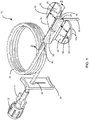
FIG. 1 is a top perspective view of the present infusion device featuring a winged hub having top ribs; -
FIG. 2 is a vertical cross-section taken along the line 2-2 ofFIG. 1 and in the direction generally indicated; -
FIG. 3 is a top view of the present hub featuring angled bottom ribs; -
FIG. 4 is a vertical cross-section taken along the line 4-4 ofFIG. 3 and in the direction generally indicated; -
FIG. 5 is a front view of the winged hub folded away from a needle in preparation of an insertion of the needle into an infusion site; -
FIG. 6 is a perspective view of the present infusion device being inserted into the infusion site; -
FIG. 7 is a perspective view of the present infusion device during infusion; and -
FIG. 8 is an enlarged perspective view of the winged hub after the needle is inserted into the infusion site. - Referring now to
FIGs. 1-2 , the present subcutaneous infusion device is generally designated 10 and is designed for subcutaneously delivering a medicinal substance below the dermis and epidermis. An exemplary medicinal substance may include nutritional products and Chinese herbal medicinal products. It is contemplated that thedevice 10 is disposable. Included in thedevice 10 is aluer cap 12 configured for receiving the liquid at one end, and at an opposite end, is attached to afemale luer connector 14 using complementary helically threaded portions for threadably fastening the cap and connector together. For carrying a viscous liquid medicine to an infusion site, a flexibleelongated tube 16 is attached at one end to thefemale luer connector 14, and at an opposite end to afoldable hub 18 having a left orfirst wing 20 and a right orsecond wing 22. - An exemplary length of the
tube 16 is approximately 61 cm (24 inches), but it is also contemplated that any length of tube can be utilized to suit different applications. Regulating a flow of the viscous liquid medicine in thetube 16 is achieved by transversely adjusting aslide clamp 24 relative to a longitudinal axis of the tube. As an example, amovable release slot 26 is provided in a center of theslide clamp 24 such that the clamp can transition between an occluding position and a non-occluding position by selectively sliding the release slot relative to thetube 16. - In a preferred embodiment, the
winged hub 18 is molded, as by injection molding or the like, such that the hub and its connecting elements are integrally formed. However, it is also contemplated that thehub 18 is attachable to the connecting elements by chemical adhesives, solvent boding, ultrasonic welding or other conventional fastening techniques. More specifically, thehub 18 is attached at one end to thetube 16, and at an opposite end to aneedle 28, which is slidably fitted into and safeguarded by aneedle protector 30 when not in use. It is contemplated that after thehub 18 is molded, theneedle 28 is assembled onto thehub 18 using an adhesive. Alternatively, thehub 18 may be over-molded over theneedle 28. - An exemplary needle size is approximately 24G for ensuring comfort during infusion, and an exemplary needle length may be one of 6, 9, or 12 mm (or millimeter) depending on an application. Preferably, the
needle 28 has a thin tubular wall for accommodating the viscous liquid medicine. - An important aspect of the
present hub 18 is that each of the foldable left andright wings top rib top rib upper surface 36 of thecorresponding wing top ribs upper surface 36 of a corresponding opposite wing. As a result, thetop rib 32 disposed on theleft wing 20 engages theupper surface 36 of theright wing 22, and conversely thetop rib 34 disposed on theright wing 22 engages theupper surface 36 of theleft wing 20. - As illustrated in an exemplary
FIGs. 1 and5 embodiment, a left or firsttop rib 32 is asymmetrically disposed from a right or secondtop rib 34 such that the firsttop rib 32 is juxtaposed with the secondtop rib 34 when thewings needle 28 and pinched together (FIG. 5 ). More specifically, the firsttop rib 32 is spaced in parallel from anelongated center section 38 of thehub 18 at a first predetermined distance DA (FIG. 1 ), but the secondtop rib 34 is spaced in parallel from the center section at a second predetermined distance DB (FIG. 1 ), where the first distance DA is different from the second distance DB. - For example, as best shown in the
FIG. 5 embodiment, the first distance DA is longer than the second distance DB, and thefirst rib 32 goes over thesecond rib 34 such that theribs wings top ribs wings needle 28 during the insertion of the needle into the skin. - Returning now to
FIGs. 1-2 , afirst insertion opening 40 at a first end of thecenter section 38 is configured for accommodating insertion of theneedle 28, and a second insertion opening 42 at a second opposite end of the center section in fluid communication with thetube 16 is configured for accommodating insertion of the tube. In a preferred embodiment, thetube 16 is inserted into thefirst insertion opening 40 approximately half a length of thecenter section 38 to reduce a total length of the needle 28 (FIG. 2 ). - Both
openings stainless needle 28 having the thin tubular wall is configured for accommodating the viscous liquid medicine, and amid-region 44 of theneedle 28 is slightly bent at a predetermined radius of curvature (e.g., 3.175 mm (0.125") typically and not less than 1.524 mm (0.060") or more than 5.08 mm (0.200")), such that the mid-region of the needle surrounds asupport region 46 located at or near thefirst insertion opening 40 of thecenter section 38. - It is preferred that the
mid-region 44 of theneedle 28 is bent gradually at an angle of 45 to 90 degrees (nominally close to 90 degrees), such that thesupport region 46 buttresses against the bent mid-region of the needle. A sharp end of theneedle 28 extends outwardly from thefirst insertion opening 40 of thecenter section 38 so that the sharp end of the needle is disposed transverse to a longitudinal axis of the center section. Consequently, thesupport region 46 reduces the risk of needle breakage, and provides integrated support for thebent mid-region 44 not only during the insertion of theneedle 28 into the skin but also while being attached to the user's body. - Referring now to
FIGs. 2-4 and8 , a plurality of substantially diagonally disposedbottom ribs bottom surface 50 of eachwing hub 18 during use. It is preferred that thebottom ribs corresponding wing bottom ribs needle 28 is prevented, while a backward movement away from the sharp end of the needle is allowed. This particular arrangement reduces shear and/or normal stress on thebent mid-region 44 of theneedle 28 during use. - In a preferred embodiment, both the first and
second wings hub 18 have thebottom ribs lower surface 50 at an angle of approximately 45 degrees relative to the longitudinal axis of thecenter section 38. An important aspect of theribs bottom rib 48a disposed on thelower surface 50 of thefirst wing 20 is inclined or sloped upwardly from a left side of the first wing to a right side of the first wing toward thecenter section 38. In a mirrored orientation, eachbottom rib 48b disposed on thelower surface 50 of thesecond wing 22 is declined or sloped downwardly from a left side of the second wing adjacent thecenter section 38 to a right side of the second wing. As a whole, thebottom ribs hub 18 while being attached to the user's body. - This enhanced friction provided by the
ribs hub 18 from the skin during use. While diagonally arrangedribs lower surface 50 of thewings ribs - Referring now to
FIGs. 5-7 , an exemplary use of the present infusion device is illustrated in greater detail. Before inserting theneedle 28 into the skin, the user folds thewings needle 28 and pinches the wings together between two fingers. Then, the user subsequently removes theneedle protector 30 from theneedle 28, and discards the protector (FIG. 5 ). In preparation of the insertion, the user pinches an inch of the cleansed skin at the desired infusion site, and inserts theneedle 28 with a darting motion, straight into the infusion site at a 90 degree angle (FIG. 6 ). Next, the user checks a needle placement with asyringe 52 by pulling aplunger 54 backward. If blood is seen in thesyringe 52, then thepresent device 10 is removed and discarded in case of a disposable device. Otherwise, the user repeats the process of preparing thepresent device 10 and the infusion site. If no blood is seen in thesyringe 52, the user secures theneedle 28 in place, and starts infusion as directed by a healthcare professional (FIGs. 7-8 ). - While a particular embodiment of the present infusion device has been shown and described, it will be appreciated by those skilled in the art that changes and modifications may be made thereto without departing from the present disclosure in its broader aspects and as set forth in the following claims.
Claims (15)
- A medical delivery device for delivering a medicinal substance into a user's body, comprising:a foldable hub (18) having a left wing (20) and a right wing (22), the hub being attached at one end to a tube (16), and attached at an opposite end to a needle (28); andwherein at least one first rib (32) is disposed on the left wing and at least one second rib (34) is disposed on the right wing, such that when the wings are folded back away from the needle and pinched together, the first and second ribs prevent twisting and/or sliding of the wings relative to each other during an insertion of the needle into a user's skin, thereby preventing a breakage of the needle due to undesirable movement of the wings, andwherein the at least one first rib (32) is spaced in parallel from a center section (38) of the hub (18) at a first predetermined distance, and the at least one second rib (34) is spaced in parallel from the center section at a second predetermined distance, the first distance being different from the second distance;wherein the needle (28) has a thin tubular wall configured for accommodating the medicinal substance, wherein a mid-region (44) of the needle is slightly bent at a predetermined radius of curvature, such that the mid-region surrounds a support region (46) located at an outer end of the hub, and wherein the mid-region (44) of the needle is bent gradually at an angle of 45 to 90 degrees, such that the support region (46) buttresses against the bent mid-region of the needle.
- The medical delivery device of claim 1, wherein the at least one first and second ribs (32, 34) extend along an entire longitudinal length of a corresponding wing (20, 22).
- The medical delivery device of claim 1, wherein each of the at least one first and second ribs (32, 34) is disposed on an upper surface (36) of a corresponding wing (20, 22) such that when the wings are folded, the at least one first and second ribs are directly in contact with the upper surface of a corresponding opposite wing.
- The medical delivery device of claim 1, wherein the at least one first rib (32) is asymmetrically disposed from the at least one second rib (34) such that the at least one first rib is juxtaposed with the at least one second rib when the wings are folded back away from the needle and pinched together.
- The medical delivery device of claim 1, wherein a first insertion opening (40) at a first end of the center section (38) is configured for accommodating insertion of the needle (28), and a second insertion opening (42) at a second opposite end of the center section in fluid communication with the tube (16) is configured for accommodating insertion of the tube.
- The medical delivery device of claim 5, wherein the tube (16) is inserted into the first insertion opening (40) approximately half a length of the center section (38) for reducing a total length of the needle.
- The medical delivery device of claim 1, further comprising a luer cap (12) configured for receiving the substance at one end, and at an opposite end, being attached to a female luer connector (14).
- The medical delivery device of claim 1, further comprising a flexible elongated tube (16) being attached at one end to a female luer connector (14), and at an opposite end, attached to the foldable hub (18), and a slide clamp (24) configured for regulating a flow of the substance in the tube by transversely adjusting the clamp relative to a longitudinal axis of the tube.
- The medical delivery device of claim 1, wherein each of the at least one first and second ribs (32, 34) is disposed on an upper surface (36) of a corresponding wing (20, 22) and wherein the device further comprises a plurality of substantially diagonally disposed ribs (48) on a bottom surface (50) of each wing, the plurality of ribs configured for preventing unwanted movement of the hub (18) during infusion, wherein the ribs are angled such that a forward movement toward a sharp end of the needle is prevented while a backward movement away from the sharp end of the needle is allowed.
- The medical delivery device of claim 9, wherein the ribs (48) on the bottom surface (50) of each wing are generally evenly spaced in parallel, and extend along a full diagonal length of a corresponding wing (20, 22).
- The medical delivery device of claim 9, wherein the ribs (48) on the bottom surface (50) of each wing (20, 22) are positioned at an angle of approximately 45 degrees relative to a longitudinal axis of a center section (38) of the hub.
- The medical delivery device of claim 9, wherein a first insertion opening (40) at a first end of the hub (18) is configured for accommodating insertion of the needle (28), and a second insertion opening (42) at a second opposite end of the hub in fluid communication with the tube (16) is configured for accommodating insertion of the tube.
- The medical delivery device of claim 11, wherein each rib (48) on the bottom surface of the left wing (20) is inclined or sloped upwardly from a left side of the left wing to a right side of the left wing toward the center section (38).
- The medical delivery device of claim 11, wherein each rib (48) on the bottom surface of the right wing (22) is declined or sloped downwardly from a left side of the right wing adjacent the center section (38) to a right side of the right wing.
- The medical delivery device of claim 9, wherein the plurality of ribs (48) disposed on the bottom surface (50) of the wings are constructed and arranged in a chevron or herringbone pattern.
Priority Applications (6)
| Application Number | Priority Date | Filing Date | Title |
|---|---|---|---|
| SM20200040T SMT202000040T1 (en) | 2014-03-28 | 2015-03-25 | Subcutaneous infusion device for injecting medicinal substances |
| PL15715591T PL3122404T3 (en) | 2014-03-28 | 2015-03-25 | Subcutaneous infusion device for injecting medicinal substances |
| SI201531051T SI3122404T1 (en) | 2014-03-28 | 2015-03-25 | Subcutaneous infusion device for injecting medicinal substances |
| EP19205633.1A EP3656424A1 (en) | 2014-03-28 | 2015-03-25 | A subcutaneous infusion device for injecting medicinal substances |
| HRP20192292TT HRP20192292T1 (en) | 2014-03-28 | 2015-03-25 | SUBCUTANEOUS INFUSION DEVICE FOR INJECTION OF MEDICAL SUBSTANCES |
| RS20191696A RS59866B1 (en) | 2014-03-28 | 2015-03-25 | Subcutaneous infusion device for injecting medicinal substances |
Applications Claiming Priority (2)
| Application Number | Priority Date | Filing Date | Title |
|---|---|---|---|
| US201461971966P | 2014-03-28 | 2014-03-28 | |
| PCT/US2015/022494 WO2015148667A1 (en) | 2014-03-28 | 2015-03-25 | Subcutaneous infusion device for injecting medicinal substances |
Related Child Applications (1)
| Application Number | Title | Priority Date | Filing Date |
|---|---|---|---|
| EP19205633.1A Division EP3656424A1 (en) | 2014-03-28 | 2015-03-25 | A subcutaneous infusion device for injecting medicinal substances |
Publications (2)
| Publication Number | Publication Date |
|---|---|
| EP3122404A1 EP3122404A1 (en) | 2017-02-01 |
| EP3122404B1 true EP3122404B1 (en) | 2019-10-30 |
Family
ID=52823849
Family Applications (2)
| Application Number | Title | Priority Date | Filing Date |
|---|---|---|---|
| EP15715591.2A Active EP3122404B1 (en) | 2014-03-28 | 2015-03-25 | Subcutaneous infusion device for injecting medicinal substances |
| EP19205633.1A Pending EP3656424A1 (en) | 2014-03-28 | 2015-03-25 | A subcutaneous infusion device for injecting medicinal substances |
Family Applications After (1)
| Application Number | Title | Priority Date | Filing Date |
|---|---|---|---|
| EP19205633.1A Pending EP3656424A1 (en) | 2014-03-28 | 2015-03-25 | A subcutaneous infusion device for injecting medicinal substances |
Country Status (21)
| Country | Link |
|---|---|
| US (2) | US10632252B2 (en) |
| EP (2) | EP3122404B1 (en) |
| JP (3) | JP6851829B2 (en) |
| CN (2) | CN107073209B (en) |
| AU (3) | AU2015236125B2 (en) |
| CA (2) | CA2943994C (en) |
| CY (1) | CY1122802T1 (en) |
| DK (1) | DK3122404T3 (en) |
| EA (1) | EA034470B1 (en) |
| ES (1) | ES2767096T3 (en) |
| HR (1) | HRP20192292T1 (en) |
| HU (1) | HUE047154T2 (en) |
| LT (1) | LT3122404T (en) |
| MX (2) | MX378070B (en) |
| NZ (1) | NZ762033A (en) |
| PL (1) | PL3122404T3 (en) |
| PT (1) | PT3122404T (en) |
| RS (1) | RS59866B1 (en) |
| SI (1) | SI3122404T1 (en) |
| SM (1) | SMT202000040T1 (en) |
| WO (1) | WO2015148667A1 (en) |
Cited By (1)
| Publication number | Priority date | Publication date | Assignee | Title |
|---|---|---|---|---|
| WO2024133185A1 (en) * | 2022-12-20 | 2024-06-27 | Fresenius Kabi Deutschland Gmbh | Port cannula with bendable needle |
Families Citing this family (2)
| Publication number | Priority date | Publication date | Assignee | Title |
|---|---|---|---|---|
| US20190201620A1 (en) * | 2017-12-29 | 2019-07-04 | Repro-Med Systems, Inc. | High flow at low pressure infusion system and method |
| USD928947S1 (en) * | 2018-09-10 | 2021-08-24 | Emd Millipore Corporation | Needle protector |
Citations (2)
| Publication number | Priority date | Publication date | Assignee | Title |
|---|---|---|---|---|
| US20030163096A1 (en) * | 2002-02-28 | 2003-08-28 | Becton, Dickinson And Company | Shieldable fluid collection set |
| US20090187153A1 (en) * | 2008-01-14 | 2009-07-23 | West Richard L | Winged needle assembly and frangible cover |
Family Cites Families (35)
| Publication number | Priority date | Publication date | Assignee | Title |
|---|---|---|---|---|
| US3589361A (en) * | 1968-06-10 | 1971-06-29 | Abbott Lab | Intravenous catheter unit with flexible wing support and inserter means |
| US3538915A (en) * | 1968-09-12 | 1970-11-10 | Deseret Pharma | Infustion device and method |
| US3670727A (en) * | 1970-04-16 | 1972-06-20 | American Hospital Supply Corp | Medical infusion set |
| US3640275A (en) * | 1970-05-05 | 1972-02-08 | Burron Medical Prod Inc | Intravenous needle assembly |
| DE2852843A1 (en) | 1977-12-23 | 1979-06-28 | Erba Carlo Spa | NEEDLE FOR TRANSFUSIONS, INFUSIONS, ETC. |
| US4710175A (en) * | 1983-08-19 | 1987-12-01 | Deseret Medical, Inc. | Intravenous infusion assembly formed as an integral part |
| US4698057A (en) * | 1986-06-09 | 1987-10-06 | Joishy Suresh K | Built in assembly for stabilizing and securing intravascular needle or catheter like device |
| US4834708A (en) * | 1987-03-31 | 1989-05-30 | George Pillari | Puncture needle assembly |
| US4867172A (en) * | 1988-02-23 | 1989-09-19 | Habley Medical Technology Corporation | Collapsible blood collector |
| US5149328A (en) * | 1990-12-31 | 1992-09-22 | Abbott Laboratories | Intravenous needle assembly having interlocking wings |
| GB2274783B (en) * | 1993-02-03 | 1996-12-11 | Graham Cameron Grant | Intravenous infusion set with needle protection |
| US5306253A (en) * | 1993-03-17 | 1994-04-26 | Becton, Dickinson And Company | Winged catheter introducer with pre-bent wings |
| US6786892B2 (en) * | 1993-03-19 | 2004-09-07 | Venetec International, Inc. | Catheter anchoring system |
| US5584813A (en) * | 1995-06-07 | 1996-12-17 | Minimed Inc. | Subcutaneous injection set |
| JP2000084076A (en) * | 1998-09-09 | 2000-03-28 | Shinji Kondo | Injection needle and injection needle protective cap |
| JP4305704B2 (en) * | 2000-03-10 | 2009-07-29 | 株式会社ジェイ・エム・エス | Wing needle device |
| US6537255B1 (en) * | 2000-10-09 | 2003-03-25 | B Braun Medical, Inc. | Huber needle with folding safety wings |
| US7316679B2 (en) * | 2001-01-22 | 2008-01-08 | Venetec International, Inc. | Medical device connector fitting |
| US6500155B2 (en) * | 2001-02-13 | 2002-12-31 | Churchill Medical Systems, Inc. | Safety angled indwelling needle and a protective shield for a safety angled indwelling needle |
| BR0117148A (en) * | 2001-10-11 | 2004-11-23 | Jms Co Ltd | Medical needle device with finned sheath to prevent accidental needle stick |
| US6921388B2 (en) * | 2002-11-04 | 2005-07-26 | Becton Dickinson Co | Needle assembly |
| US6997902B2 (en) * | 2003-11-13 | 2006-02-14 | David L. Thorne | Safety shield for medical needles |
| EP1682202B1 (en) | 2003-11-13 | 2010-05-26 | Specialized Health Products, Inc. | Safety shield for medical needles |
| US7776016B1 (en) * | 2004-02-26 | 2010-08-17 | C. R. Bard, Inc. | Huber needle safety enclosure |
| JP4319601B2 (en) * | 2004-08-26 | 2009-08-26 | 川澄化学工業株式会社 | Curved needle with wings |
| WO2007126085A1 (en) * | 2006-04-28 | 2007-11-08 | Nipro Corporation | Safety needle assembly |
| US20100010451A1 (en) * | 2006-05-26 | 2010-01-14 | Avtar Singh Kashmirian | Huber Needle Assembly and Method of Use |
| US20080177234A1 (en) * | 2006-11-21 | 2008-07-24 | Candace Keaton | Safety subcutaneous infusion set |
| DE102008002854A1 (en) * | 2008-05-15 | 2009-11-19 | Süddeutsche Feinmechanik GmbH | The cannula assembly |
| US8231582B2 (en) * | 2008-12-11 | 2012-07-31 | Bard Access Systems, Inc. | Device for removing a Huber needle from a patient |
| US20120041253A1 (en) | 2010-08-10 | 2012-02-16 | Ching-Yang Wu | Protective Apparatus for Chemotherapy Injection Needle |
| EP2613824A1 (en) * | 2010-09-10 | 2013-07-17 | C.R. Bard Inc. | Systems for isolation of a needle-based infusion set |
| ES2806549T3 (en) * | 2012-03-07 | 2021-02-18 | Medical Components Inc | A set of Huber needle |
| DE102012102519A1 (en) * | 2012-03-23 | 2013-09-26 | Pfm Medical Ag | Safety pin device, in particular for puncturing a subcutaneously implanted port in a human or animal body |
| JP5579823B2 (en) * | 2012-12-18 | 2014-08-27 | 川澄化学工業株式会社 | Medical needle |
-
2015
- 2015-03-25 CN CN201580017380.2A patent/CN107073209B/en active Active
- 2015-03-25 HR HRP20192292TT patent/HRP20192292T1/en unknown
- 2015-03-25 WO PCT/US2015/022494 patent/WO2015148667A1/en not_active Ceased
- 2015-03-25 EP EP15715591.2A patent/EP3122404B1/en active Active
- 2015-03-25 PL PL15715591T patent/PL3122404T3/en unknown
- 2015-03-25 HU HUE15715591A patent/HUE047154T2/en unknown
- 2015-03-25 NZ NZ762033A patent/NZ762033A/en unknown
- 2015-03-25 EP EP19205633.1A patent/EP3656424A1/en active Pending
- 2015-03-25 AU AU2015236125A patent/AU2015236125B2/en active Active
- 2015-03-25 CN CN202011419181.3A patent/CN112657014B/en active Active
- 2015-03-25 LT LTEP15715591.2T patent/LT3122404T/en unknown
- 2015-03-25 ES ES15715591T patent/ES2767096T3/en active Active
- 2015-03-25 MX MX2016012637A patent/MX378070B/en unknown
- 2015-03-25 CA CA2943994A patent/CA2943994C/en active Active
- 2015-03-25 RS RS20191696A patent/RS59866B1/en unknown
- 2015-03-25 EA EA201600666A patent/EA034470B1/en not_active IP Right Cessation
- 2015-03-25 CA CA3117037A patent/CA3117037A1/en active Pending
- 2015-03-25 SI SI201531051T patent/SI3122404T1/en unknown
- 2015-03-25 SM SM20200040T patent/SMT202000040T1/en unknown
- 2015-03-25 PT PT157155912T patent/PT3122404T/en unknown
- 2015-03-25 US US15/300,020 patent/US10632252B2/en active Active
- 2015-03-25 JP JP2016559616A patent/JP6851829B2/en active Active
- 2015-03-25 DK DK15715591.2T patent/DK3122404T3/en active
-
2016
- 2016-09-27 MX MX2020005655A patent/MX2020005655A/en unknown
-
2019
- 2019-10-18 AU AU2019250262A patent/AU2019250262B2/en active Active
- 2019-11-27 JP JP2019214567A patent/JP7408360B2/en active Active
-
2020
- 2020-01-21 CY CY20201100052T patent/CY1122802T1/en unknown
- 2020-03-20 US US16/825,961 patent/US20200282132A1/en not_active Abandoned
-
2021
- 2021-07-30 AU AU2021209323A patent/AU2021209323B2/en active Active
-
2022
- 2022-10-26 JP JP2022171142A patent/JP7500684B2/en active Active
Patent Citations (2)
| Publication number | Priority date | Publication date | Assignee | Title |
|---|---|---|---|---|
| US20030163096A1 (en) * | 2002-02-28 | 2003-08-28 | Becton, Dickinson And Company | Shieldable fluid collection set |
| US20090187153A1 (en) * | 2008-01-14 | 2009-07-23 | West Richard L | Winged needle assembly and frangible cover |
Cited By (1)
| Publication number | Priority date | Publication date | Assignee | Title |
|---|---|---|---|---|
| WO2024133185A1 (en) * | 2022-12-20 | 2024-06-27 | Fresenius Kabi Deutschland Gmbh | Port cannula with bendable needle |
Also Published As
Similar Documents
| Publication | Publication Date | Title |
|---|---|---|
| US11541172B2 (en) | Infusion set with safety device | |
| JP7500684B2 (en) | Subcutaneous infusion device for injecting medicines | |
| EP3532128A1 (en) | Medical device with reduced occlusion | |
| EP3659646B1 (en) | Tactile features to guide user interaction with fluid connector | |
| US20190321548A1 (en) | Catheter having a cannula with both an end opening and a plurality of perforations in the cannula wall | |
| HK1232478A1 (en) | Subcutaneous infusion device for injecting medicinal substances | |
| HK1232478B (en) | Subcutaneous infusion device for injecting medicinal substances | |
| HK40048812A (en) | Subcutaneous infusion device for injecting medicinal substances | |
| HK40030166A (en) | A subcutaneous infusion device for injecting medicinal substances | |
| HK40048812B (en) | Subcutaneous infusion device for injecting medicinal substances | |
| NZ724349B2 (en) | Subcutaneous infusion device for injecting medicinal substances | |
| RU2806631C2 (en) | Safety mechanism for huber needle assembly |
Legal Events
| Date | Code | Title | Description |
|---|---|---|---|
| STAA | Information on the status of an ep patent application or granted ep patent |
Free format text: STATUS: THE INTERNATIONAL PUBLICATION HAS BEEN MADE |
|
| PUAI | Public reference made under article 153(3) epc to a published international application that has entered the european phase |
Free format text: ORIGINAL CODE: 0009012 |
|
| STAA | Information on the status of an ep patent application or granted ep patent |
Free format text: STATUS: REQUEST FOR EXAMINATION WAS MADE |
|
| 17P | Request for examination filed |
Effective date: 20161027 |
|
| AK | Designated contracting states |
Kind code of ref document: A1 Designated state(s): AL AT BE BG CH CY CZ DE DK EE ES FI FR GB GR HR HU IE IS IT LI LT LU LV MC MK MT NL NO PL PT RO RS SE SI SK SM TR |
|
| AX | Request for extension of the european patent |
Extension state: BA ME |
|
| DAV | Request for validation of the european patent (deleted) | ||
| DAX | Request for extension of the european patent (deleted) | ||
| REG | Reference to a national code |
Ref country code: HK Ref legal event code: DE Ref document number: 1232478 Country of ref document: HK |
|
| STAA | Information on the status of an ep patent application or granted ep patent |
Free format text: STATUS: EXAMINATION IS IN PROGRESS |
|
| 17Q | First examination report despatched |
Effective date: 20180920 |
|
| REG | Reference to a national code |
Ref country code: DE Ref legal event code: R079 Ref document number: 602015040673 Country of ref document: DE Free format text: PREVIOUS MAIN CLASS: A61M0005320000 Ipc: A61M0039200000 |
|
| GRAP | Despatch of communication of intention to grant a patent |
Free format text: ORIGINAL CODE: EPIDOSNIGR1 |
|
| STAA | Information on the status of an ep patent application or granted ep patent |
Free format text: STATUS: GRANT OF PATENT IS INTENDED |
|
| RIC1 | Information provided on ipc code assigned before grant |
Ipc: A61M 39/28 20060101ALI20190408BHEP Ipc: A61M 39/20 20060101AFI20190408BHEP Ipc: A61M 5/32 20060101ALI20190408BHEP Ipc: A61M 5/158 20060101ALI20190408BHEP |
|
| INTG | Intention to grant announced |
Effective date: 20190514 |
|
| GRAS | Grant fee paid |
Free format text: ORIGINAL CODE: EPIDOSNIGR3 |
|
| GRAA | (expected) grant |
Free format text: ORIGINAL CODE: 0009210 |
|
| STAA | Information on the status of an ep patent application or granted ep patent |
Free format text: STATUS: THE PATENT HAS BEEN GRANTED |
|
| AK | Designated contracting states |
Kind code of ref document: B1 Designated state(s): AL AT BE BG CH CY CZ DE DK EE ES FI FR GB GR HR HU IE IS IT LI LT LU LV MC MK MT NL NO PL PT RO RS SE SI SK SM TR |
|
| REG | Reference to a national code |
Ref country code: GB Ref legal event code: FG4D |
|
| REG | Reference to a national code |
Ref country code: CH Ref legal event code: EP |
|
| REG | Reference to a national code |
Ref country code: DE Ref legal event code: R096 Ref document number: 602015040673 Country of ref document: DE |
|
| REG | Reference to a national code |
Ref country code: AT Ref legal event code: REF Ref document number: 1195505 Country of ref document: AT Kind code of ref document: T Effective date: 20191115 |
|
| REG | Reference to a national code |
Ref country code: IE Ref legal event code: FG4D |
|
| REG | Reference to a national code |
Ref country code: HR Ref legal event code: TUEP Ref document number: P20192292T Country of ref document: HR |
|
| REG | Reference to a national code |
Ref country code: RO Ref legal event code: EPE |
|
| REG | Reference to a national code |
Ref country code: FI Ref legal event code: FGE |
|
| REG | Reference to a national code |
Ref country code: SE Ref legal event code: TRGR |
|
| REG | Reference to a national code |
Ref country code: DK Ref legal event code: T3 Effective date: 20200127 Ref country code: PT Ref legal event code: SC4A Ref document number: 3122404 Country of ref document: PT Date of ref document: 20200203 Kind code of ref document: T Free format text: AVAILABILITY OF NATIONAL TRANSLATION Effective date: 20200120 |
|
| REG | Reference to a national code |
Ref country code: NO Ref legal event code: T2 Effective date: 20191030 |
|
| REG | Reference to a national code |
Ref country code: NL Ref legal event code: FP |
|
| REG | Reference to a national code |
Ref country code: EE Ref legal event code: FG4A Ref document number: E018556 Country of ref document: EE Effective date: 20191219 |
|
| REG | Reference to a national code |
Ref country code: HR Ref legal event code: T1PR Ref document number: P20192292 Country of ref document: HR |
|
| REG | Reference to a national code |
Ref country code: SK Ref legal event code: T3 Ref document number: E 33202 Country of ref document: SK |
|
| REG | Reference to a national code |
Ref country code: HR Ref legal event code: ODRP Ref document number: P20192292 Country of ref document: HR Payment date: 20200225 Year of fee payment: 6 |
|
| REG | Reference to a national code |
Ref country code: HU Ref legal event code: AG4A Ref document number: E047154 Country of ref document: HU |
|
| REG | Reference to a national code |
Ref country code: GR Ref legal event code: EP Ref document number: 20200400271 Country of ref document: GR Effective date: 20200511 |
|
| PGFP | Annual fee paid to national office [announced via postgrant information from national office to epo] |
Ref country code: SM Payment date: 20200219 Year of fee payment: 6 |
|
| REG | Reference to a national code |
Ref country code: ES Ref legal event code: FG2A Ref document number: 2767096 Country of ref document: ES Kind code of ref document: T3 Effective date: 20200616 |
|
| REG | Reference to a national code |
Ref country code: DE Ref legal event code: R097 Ref document number: 602015040673 Country of ref document: DE |
|
| REG | Reference to a national code |
Ref country code: AT Ref legal event code: UEP Ref document number: 1195505 Country of ref document: AT Kind code of ref document: T Effective date: 20191030 |
|
| PLBE | No opposition filed within time limit |
Free format text: ORIGINAL CODE: 0009261 |
|
| STAA | Information on the status of an ep patent application or granted ep patent |
Free format text: STATUS: NO OPPOSITION FILED WITHIN TIME LIMIT |
|
| 26N | No opposition filed |
Effective date: 20200731 |
|
| REG | Reference to a national code |
Ref country code: CH Ref legal event code: PUE Owner name: TAKEDA PHARMACEUTICAL COMPANY LIMITED, JP Free format text: FORMER OWNER: BAXALTA INCORPORATED, CH |
|
| REG | Reference to a national code |
Ref country code: NO Ref legal event code: CREP Representative=s name: BRYN AARFLOT AS, STORTINGSGATA 8, 0161 OSLO, NORGE Ref country code: NO Ref legal event code: CHAD Owner name: TAKEDA PHARMACEUTICAL COMPANY LIMITED, JP |
|
| REG | Reference to a national code |
Ref country code: EE Ref legal event code: GB1A Ref document number: E018556 Country of ref document: EE |
|
| REG | Reference to a national code |
Ref country code: FI Ref legal event code: PCE Owner name: TAKEDA PHARMACEUTICAL COMPANY LIMITED |
|
| REG | Reference to a national code |
Ref country code: HU Ref legal event code: GB9C Owner name: TAKEDA PHARMACEUTICAL COMPANY LIMITED, JP Free format text: FORMER OWNER(S): BAXALTA INCORPORATED, US; BAXALTA GMBH, CH |
|
| REG | Reference to a national code |
Ref country code: HR Ref legal event code: ODRP Ref document number: P20192292 Country of ref document: HR Payment date: 20210322 Year of fee payment: 7 |
|
| REG | Reference to a national code |
Ref country code: LU Ref legal event code: PD Owner name: TAKEDA PHARMACEUTICAL COMPANY LIMITED; JP Free format text: FORMER OWNER: BAXALTA GMBH Effective date: 20210419 |
|
| REG | Reference to a national code |
Ref country code: HR Ref legal event code: PPPP Ref document number: P20192292 Country of ref document: HR Owner name: TAKEDA PHARMACEUTICAL COMPANY LIMITED, JP |
|
| REG | Reference to a national code |
Ref country code: DE Ref legal event code: R081 Ref document number: 602015040673 Country of ref document: DE Owner name: TAKEDA PHARMACEUTICAL COMPANY LIMITED, OSAKA-S, JP Free format text: FORMER OWNERS: BAXALTA GMBH, GLATTPARK, OPFIKON, CH; BAXALTA INCORPORATED, BANNOCKBURN, ILL., US Ref country code: DE Ref legal event code: R081 Ref document number: 602015040673 Country of ref document: DE Owner name: TAKEDA PHARMACEUTICAL CO. LTD., JP Free format text: FORMER OWNERS: BAXALTA GMBH, GLATTPARK, OPFIKON, CH; BAXALTA INCORPORATED, BANNOCKBURN, ILL., US |
|
| REG | Reference to a national code |
Ref country code: NL Ref legal event code: PD Owner name: TAKEDA PHARMACEUTICAL COMPANY LIMITED; JP Free format text: DETAILS ASSIGNMENT: CHANGE OF OWNER(S), ASSIGNMENT; FORMER OWNER NAME: BAXALTA INCORPORATED Effective date: 20210617 |
|
| REG | Reference to a national code |
Ref country code: SK Ref legal event code: PC4A Ref document number: E 33202 Country of ref document: SK Owner name: TAKEDA PHARMACEUTICAL COMPANY LIMITED, CHUO-KU, JP Free format text: FORMER OWNER: BAXALTA INCORPORATED, BANNOCKBURN, IL, US; BAXALTA GMBH, GLATTPARK, OPFIKON, CH Effective date: 20210819 |
|
| REG | Reference to a national code |
Ref country code: AT Ref legal event code: PC Ref document number: 1195505 Country of ref document: AT Kind code of ref document: T Owner name: TAKEDA PHARMACEUTICAL COMPANY LIMITED, JP Effective date: 20210719 |
|
| REG | Reference to a national code |
Ref country code: BE Ref legal event code: PD Owner name: TAKEDA PHARMACEUTICAL COMPANY LIMITED; JP Free format text: DETAILS ASSIGNMENT: CHANGE OF OWNER(S), ASSIGNMENT; FORMER OWNER NAME: BAXALTA GMBH Effective date: 20210401 |
|
| REG | Reference to a national code |
Ref country code: SI Ref legal event code: SP73 Owner name: TAKEDA PHARMACEUTICAL COMPANY LIMITED; JP Effective date: 20210930 |
|
| PG25 | Lapsed in a contracting state [announced via postgrant information from national office to epo] |
Ref country code: SM Free format text: LAPSE BECAUSE OF NON-PAYMENT OF DUE FEES Effective date: 20211007 |
|
| REG | Reference to a national code |
Ref country code: GB Ref legal event code: 732E Free format text: REGISTERED BETWEEN 20220210 AND 20220216 |
|
| REG | Reference to a national code |
Ref country code: ES Ref legal event code: PC2A Owner name: TAKEDA PHARMACEUTICAL COMPANY LIMITED Effective date: 20220418 |
|
| REG | Reference to a national code |
Ref country code: HR Ref legal event code: ODRP Ref document number: P20192292 Country of ref document: HR Payment date: 20220324 Year of fee payment: 8 |
|
| REG | Reference to a national code |
Ref country code: HR Ref legal event code: ODRP Ref document number: P20192292 Country of ref document: HR Payment date: 20230307 Year of fee payment: 9 |
|
| P01 | Opt-out of the competence of the unified patent court (upc) registered |
Effective date: 20230527 |
|
| REG | Reference to a national code |
Ref country code: DE Ref legal event code: R081 Ref document number: 602015040673 Country of ref document: DE Owner name: TAKEDA PHARMACEUTICAL COMPANY LIMITED, OSAKA-S, JP Free format text: FORMER OWNER: TAKEDA PHARMACEUTICAL CO. LTD., OSAKA, JP |
|
| REG | Reference to a national code |
Ref country code: HR Ref legal event code: ODRP Ref document number: P20192292 Country of ref document: HR Payment date: 20240314 Year of fee payment: 10 |
|
| REG | Reference to a national code |
Ref country code: HR Ref legal event code: ODRP Ref document number: P20192292 Country of ref document: HR Payment date: 20250317 Year of fee payment: 11 |
|
| PGFP | Annual fee paid to national office [announced via postgrant information from national office to epo] |
Ref country code: AL Payment date: 20250326 Year of fee payment: 11 |
|
| PGFP | Annual fee paid to national office [announced via postgrant information from national office to epo] |
Ref country code: ES Payment date: 20250401 Year of fee payment: 11 |
|
| PGFP | Annual fee paid to national office [announced via postgrant information from national office to epo] |
Ref country code: CH Payment date: 20250401 Year of fee payment: 11 |
|
| PGFP | Annual fee paid to national office [announced via postgrant information from national office to epo] |
Ref country code: LU Payment date: 20260219 Year of fee payment: 12 Ref country code: NL Payment date: 20260219 Year of fee payment: 12 |
|
| REG | Reference to a national code |
Ref country code: HR Ref legal event code: ODRP Ref document number: P20192292 Country of ref document: HR Payment date: 20260225 Year of fee payment: 12 |
|
| REG | Reference to a national code |
Ref country code: CH Ref legal event code: U11 Free format text: ST27 STATUS EVENT CODE: U-0-0-U10-U11 (AS PROVIDED BY THE NATIONAL OFFICE) Effective date: 20260401 |
|
| PGFP | Annual fee paid to national office [announced via postgrant information from national office to epo] |
Ref country code: SE Payment date: 20260219 Year of fee payment: 12 |
|
| PGFP | Annual fee paid to national office [announced via postgrant information from national office to epo] |
Ref country code: GB Payment date: 20260219 Year of fee payment: 12 Ref country code: LT Payment date: 20260219 Year of fee payment: 12 |
|
| PGFP | Annual fee paid to national office [announced via postgrant information from national office to epo] |
Ref country code: MC Payment date: 20260225 Year of fee payment: 12 |
|
| PGFP | Annual fee paid to national office [announced via postgrant information from national office to epo] |
Ref country code: NO Payment date: 20260223 Year of fee payment: 12 Ref country code: DE Payment date: 20260219 Year of fee payment: 12 Ref country code: DK Payment date: 20260219 Year of fee payment: 12 Ref country code: IE Payment date: 20260223 Year of fee payment: 12 |
|
| PGFP | Annual fee paid to national office [announced via postgrant information from national office to epo] |
Ref country code: HR Payment date: 20260225 Year of fee payment: 12 Ref country code: AT Payment date: 20260223 Year of fee payment: 12 |
|
| PGFP | Annual fee paid to national office [announced via postgrant information from national office to epo] |
Ref country code: FI Payment date: 20260219 Year of fee payment: 12 Ref country code: BE Payment date: 20260219 Year of fee payment: 12 Ref country code: RO Payment date: 20260302 Year of fee payment: 12 Ref country code: IT Payment date: 20260224 Year of fee payment: 12 |
|
| PGFP | Annual fee paid to national office [announced via postgrant information from national office to epo] |
Ref country code: HU Payment date: 20260313 Year of fee payment: 12 |
|
| PGFP | Annual fee paid to national office [announced via postgrant information from national office to epo] |
Ref country code: RS Payment date: 20260323 Year of fee payment: 12 |
|
| PGFP | Annual fee paid to national office [announced via postgrant information from national office to epo] |
Ref country code: IS Payment date: 20260320 Year of fee payment: 12 Ref country code: FR Payment date: 20260219 Year of fee payment: 12 |
|
| PGFP | Annual fee paid to national office [announced via postgrant information from national office to epo] |
Ref country code: TR Payment date: 20260227 Year of fee payment: 12 |
|
| PGFP | Annual fee paid to national office [announced via postgrant information from national office to epo] |
Ref country code: PT Payment date: 20260220 Year of fee payment: 12 Ref country code: CZ Payment date: 20260302 Year of fee payment: 12 |
|
| PGFP | Annual fee paid to national office [announced via postgrant information from national office to epo] |
Ref country code: GR Payment date: 20260224 Year of fee payment: 12 Ref country code: PL Payment date: 20260220 Year of fee payment: 12 Ref country code: CY Payment date: 20260220 Year of fee payment: 12 Ref country code: MT Payment date: 20260304 Year of fee payment: 12 |
|
| PGFP | Annual fee paid to national office [announced via postgrant information from national office to epo] |
Ref country code: EE Payment date: 20260227 Year of fee payment: 12 Ref country code: SK Payment date: 20260226 Year of fee payment: 12 Ref country code: LV Payment date: 20260219 Year of fee payment: 12 |
|
| PGFP | Annual fee paid to national office [announced via postgrant information from national office to epo] |
Ref country code: SI Payment date: 20260225 Year of fee payment: 12 |
|
| PGFP | Annual fee paid to national office [announced via postgrant information from national office to epo] |
Ref country code: BG Payment date: 20260225 Year of fee payment: 12 |
|
| PGFP | Annual fee paid to national office [announced via postgrant information from national office to epo] |
Ref country code: MK Payment date: 20260223 Year of fee payment: 12 |