EP3122257B1 - Ultrasound imaging system touchscreen user interface - Google Patents
Ultrasound imaging system touchscreen user interface Download PDFInfo
- Publication number
- EP3122257B1 EP3122257B1 EP14724791.0A EP14724791A EP3122257B1 EP 3122257 B1 EP3122257 B1 EP 3122257B1 EP 14724791 A EP14724791 A EP 14724791A EP 3122257 B1 EP3122257 B1 EP 3122257B1
- Authority
- EP
- European Patent Office
- Prior art keywords
- touch sensitive
- control
- imaging system
- ultrasound imaging
- recess
- Prior art date
- Legal status (The legal status is an assumption and is not a legal conclusion. Google has not performed a legal analysis and makes no representation as to the accuracy of the status listed.)
- Active
Links
Images




Classifications
-
- A—HUMAN NECESSITIES
- A61—MEDICAL OR VETERINARY SCIENCE; HYGIENE
- A61B—DIAGNOSIS; SURGERY; IDENTIFICATION
- A61B8/00—Diagnosis using ultrasonic, sonic or infrasonic waves
- A61B8/46—Ultrasonic, sonic or infrasonic diagnostic devices with special arrangements for interfacing with the operator or the patient
- A61B8/467—Ultrasonic, sonic or infrasonic diagnostic devices with special arrangements for interfacing with the operator or the patient characterised by special input means
-
- A—HUMAN NECESSITIES
- A61—MEDICAL OR VETERINARY SCIENCE; HYGIENE
- A61B—DIAGNOSIS; SURGERY; IDENTIFICATION
- A61B8/00—Diagnosis using ultrasonic, sonic or infrasonic waves
- A61B8/46—Ultrasonic, sonic or infrasonic diagnostic devices with special arrangements for interfacing with the operator or the patient
- A61B8/461—Displaying means of special interest
- A61B8/463—Displaying means of special interest characterised by displaying multiple images or images and diagnostic data on one display
-
- G—PHYSICS
- G06—COMPUTING OR CALCULATING; COUNTING
- G06F—ELECTRIC DIGITAL DATA PROCESSING
- G06F3/00—Input arrangements for transferring data to be processed into a form capable of being handled by the computer; Output arrangements for transferring data from processing unit to output unit, e.g. interface arrangements
- G06F3/01—Input arrangements or combined input and output arrangements for interaction between user and computer
- G06F3/048—Interaction techniques based on graphical user interfaces [GUI]
- G06F3/0487—Interaction techniques based on graphical user interfaces [GUI] using specific features provided by the input device, e.g. functions controlled by the rotation of a mouse with dual sensing arrangements, or of the nature of the input device, e.g. tap gestures based on pressure sensed by a digitiser
- G06F3/0488—Interaction techniques based on graphical user interfaces [GUI] using specific features provided by the input device, e.g. functions controlled by the rotation of a mouse with dual sensing arrangements, or of the nature of the input device, e.g. tap gestures based on pressure sensed by a digitiser using a touch-screen or digitiser, e.g. input of commands through traced gestures
- G06F3/04883—Interaction techniques based on graphical user interfaces [GUI] using specific features provided by the input device, e.g. functions controlled by the rotation of a mouse with dual sensing arrangements, or of the nature of the input device, e.g. tap gestures based on pressure sensed by a digitiser using a touch-screen or digitiser, e.g. input of commands through traced gestures for inputting data by handwriting, e.g. gesture or text
-
- G—PHYSICS
- G06—COMPUTING OR CALCULATING; COUNTING
- G06F—ELECTRIC DIGITAL DATA PROCESSING
- G06F3/00—Input arrangements for transferring data to be processed into a form capable of being handled by the computer; Output arrangements for transferring data from processing unit to output unit, e.g. interface arrangements
- G06F3/01—Input arrangements or combined input and output arrangements for interaction between user and computer
- G06F3/03—Arrangements for converting the position or the displacement of a member into a coded form
- G06F3/033—Pointing devices displaced or positioned by the user, e.g. mice, trackballs, pens or joysticks; Accessories therefor
- G06F3/0354—Pointing devices displaced or positioned by the user, e.g. mice, trackballs, pens or joysticks; Accessories therefor with detection of two-dimensional [2D] relative movements between the device, or an operating part thereof, and a plane or surface, e.g. 2D mice, trackballs, pens or pucks
- G06F3/03549—Trackballs
-
- G—PHYSICS
- G06—COMPUTING OR CALCULATING; COUNTING
- G06F—ELECTRIC DIGITAL DATA PROCESSING
- G06F3/00—Input arrangements for transferring data to be processed into a form capable of being handled by the computer; Output arrangements for transferring data from processing unit to output unit, e.g. interface arrangements
- G06F3/01—Input arrangements or combined input and output arrangements for interaction between user and computer
- G06F3/03—Arrangements for converting the position or the displacement of a member into a coded form
- G06F3/041—Digitisers, e.g. for touch screens or touch pads, characterised by the transducing means
- G06F3/0416—Control or interface arrangements specially adapted for digitisers
Definitions
- the following generally relates to an ultrasound imaging system and more particularly to an ultrasound imaging system touchscreen user interface.
- Ultrasound (US) imaging provides useful information about the interior characteristics (e.g., anatomical tissue, material flow, etc.) of a subject under examination.
- An ultrasound imaging system has included a probe with an ultrasound transducer array, a console, a display and a keyboard.
- the transducer array transmits an ultrasound signal into a field of view and receives echoes produced in response to the signal interacting with structure therein.
- the echoes are processed by the console, which generates images indicative of the structure that are visually presented in the display region.
- An example suitable keyboard has a coherent, flat surface, without any holes, e.g. glass, combined with a touch screen and e.g. a TFT panel.
- a keyboard is not well-suited for navigation on the surface of the keyboard by the user's hand to locate and use a control of interest of the keyboard without the user having to look at the keyboard.
- some controls will have more than one function or mode.
- such a keyboard is not well-suited making measurements, etc. with high precision.
- US 2012/289828 A1 and US 2013/261449 A1 each disclose an ultrasound imaging system according to the preamble of claims 1 and 5.
- an ultrasound imaging system includes a probe with a transducer array with at least one transducer element.
- the ultrasound imaging system further includes a console with a controller, which controls the at least one transducer element, and an echo processor.
- the ultrasound imaging system further includes a display monitor.
- the ultrasound imaging system further includes a touch screen user interface, including: a touch panel with a first major surface and a first recess in the first major surface; and at least one touch sensitive control disposed in the recess.
- the first recess comprises: a touch sensitive flat, planar surface configured for sensing a first gesture thereon which activates the touch sensitive flat, planar surface, and for sensing a subsequent gesture thereon that invokes a predetermined action of the at least one touch sensitive control.
- an ultrasound imaging system in another aspect, includes a probe with a transducer array with at least one transducer element.
- the ultrasound imaging system further includes a console with a controller, which controls the at least one transducer element, and an echo processor.
- the ultrasound imaging system further includes a display monitor.
- the ultrasound imaging system further includes a touch screen user interface, including: a touch panel with a first major surface and a first recess in the first major surface; and at least one touch sensitive control disposed in the recess.
- the first recess comprises: a second recess disposed therein, and a touch sensitive flat, actuating planar surface, the second recess, comprising a touch sensitive flat, active planar surface, wherein the touch sensitive flat, actuating planar surface senses a first gesture thereon, which activates the touch sensitive flat, active planar surface.
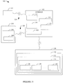
- FIG. 1 schematically illustrates an ultrasound (US) imaging system 102.
- the ultrasound imaging system 102 includes a probe 104 with a one-dimensional (ID) or two-dimensional (2D) transducer array 106 with at least one transducer element 108.
- the at least one transducer element 108 is configured to transmit ultrasound signals and receive echo signals.
- Suitable array configurations include, but are not limited to, linear, curved (e.g., concave, convex, etc.), circular, etc., full populated or sparse, etc.
- the ultrasound imaging system 102 further includes a console 112.
- the console 112 includes transmit circuitry 114 that selectively excites one or more of the at least one transducer element 108. More particularly, the transmit circuitry 114 generates a set of pulses (or a pulsed signal) that are conveyed to the transducer array 106. The set of pulses excites the at least one transducer element 108, causing the at least one transducer element 108 to transmit an ultrasound signal into an examination scan field of view.
- the console 112 further includes receive circuitry 116 that receives a set of echoes (or echo signals) generated in response to the transmitted ultrasound signals.
- the echoes generally, are a result of the interaction between the emitted ultrasound signals and the object (e.g., flowing blood cells, organ cells, etc.) in the scan field of view.
- the receive circuit 116 may be configured for spatial compounding, filtering (e.g., FIR and/or IIR), and/or other echo processing.
- the console 112 further includes an echo processor (e.g., a beamformer) 118 that processes the received echoes. For example, in B-mode, this may include applying time delays and weights to the echoes and summing the delayed and weighted echoes, and generating an image.
- the console 112 further includes a scan converter 120 that scan converts the processed data for display, e.g., by converting the beamformed data to the coordinate system of a display monitor used to visually present the processed data.
- the console 112 further includes a controller 124 that controls the various components of the system 102.
- control may include controlling the transmit circuitry 114 to excite individual or groups of the at least one transducer element 108 for an A-mode, B-mode, C-plane, and/or other data acquisition mode, steering and/or focusing the transmitted signal, etc., actuating the at least one transducer element 108 for steering and/or focusing the received echoes, etc.
- the ultrasound imaging system 102 further includes a display monitor 122.
- the display monitor 122 can be a cathode ray tube (CRT), a liquid crystal display (LCD), a light emitting diode (LED), and/or other display monitor.
- the display monitor 122 includes a display region, which can visually present images and/or flow information generated by the console 112.
- the system 102 further includes a touch screen user interface 128 with a touch panel 130.
- the touch panel 130 includes a resistive, a capacitive, an acoustic, an infrared, an optical, a piezoelectric, and/or other region.
- the touch panel 130 includes an active region(s) 132 with a touch sensitive control(s) 134.
- a touch sensitive control(s) 134 is actuated by a gesture (e.g., a press, a swipe, a touch, etc.) on the touch sensitive control(s) 134 with one or more fingers, a stylus, a glove, etc.
- Examples of the touch sensitive control(s) 134 include a trackball control 136 for navigating a graphical pointer displayed in the display region of the display monitor 122, a toggle control 138 for incrementing and decrementing value corresponding to focus, depth, zoom, etc. and/or other control(s) 140.
- a trackball control 136 for navigating a graphical pointer displayed in the display region of the display monitor 122
- a toggle control 138 for incrementing and decrementing value corresponding to focus, depth, zoom, etc.
- other control(s) 140 for incrementing and decrementing value corresponding to focus, depth, zoom, etc.
- Figure 2 an example of the touch screen user interface 128 with a plurality of the touch sensitive control(s) 134 is illustrated.
- the touch sensitive control(s) 134 include circular shaped controls 202 and 204.
- the controls 202 have a first size (i.e., diameter), and the control 204 has a second size, which is larger than the first size.
- the touch sensitive control(s) 134 include only a single size circular control or more than two sizes of circular controls.
- the illustrated number of the circular shaped controls 202 and 204 is not limiting; in a variation, there could be more or less of the circular controls 202 and 204.
- the touch sensitive control(s) 134 also include rectangular shaped controls 206 in which the rectangular shaped controls 206 include curved sides and rounded corners.
- the rectangular shaped controls 206 are the same size.
- the touch sensitive control(s) 134 include multiple different size rectangular shaped controls 206.
- the illustrated number of the rectangular shaped controls 206 is not limiting; in a variation, there could be more or less of the circular controls 202 and 204.
- the touch sensitive control(s) 134 also include oval or elliptical shaped controls 208 and 210.
- the elliptical shaped controls 208 and 210 are the same size.
- the touch sensitive control(s) 134 include multiple different size elliptical shaped controls 208 and 210.
- the illustrated number of the elliptical shaped controls 208 and 210 is not limiting; in a variation, there could be more or less of the elliptical shaped controls 208 and 210.
- the touch panel 130 may also include one or more non-active regions, a display such as a LCD, a thin film transistor (TFT) LCD, an organic light-emitting diode (OLED) and/or other display, and/or other features.
- a display such as a LCD, a thin film transistor (TFT) LCD, an organic light-emitting diode (OLED) and/or other display, and/or other features.
- TFT thin film transistor
- OLED organic light-emitting diode
- Figures 3 , 4 and 5 illustrate an example of the trackball control 136 ( Figure 1 ) implemented using the larger circular shaped control 204 ( Figure 2).
- Figure 3 shows a top down view of the trackball control 136 in connection with a sub-portion of the touch panel 130.
- Figure 4 shows a cross-sectional view of the trackball control 136 along lines A-A.
- Figure 5 shows a perspective view of the trackball control 136.
- the trackball control 136 has a first major surface 402 and a second major surface 404, which is parallel to and opposite from the first major surface 402.
- the first and second major surfaces 402 and 404 are separated by a material of the touch panel 130.
- the first and second major surfaces 402 and 404 are separated are separated by a non-zero distance 406, which is in a range of 1 to 6 millimeters (mm).
- the first major surface 402 includes a recess 408.
- the recess has a generally flat, planar active surface 410 and a side wall 412, which extends from the first major surface 402 to the generally flat, planar active surface 410 within the touch panel 130.
- the generally flat, planar surface 410 is offset from the first major surface 402 by a non-zero distance 414, which is in a range of 0.1 to 1 mm.
- the recess 408 has a diameter 418, which is in a range of 40 to 100 mm.
- the illustrated side wall 412 extends linearly or non-linearly from the first major surface 402 to the recess 408.
- the side wall 412 has a length 420, which is in a range of 0.1 to 4 mm. It is to be appreciated that the distances 406, 414, 416, 418, and 420 are provided for explanatory purposes and are not limiting. Other ranges for these distances are contemplated herein.
- the circular trackball control 136 in Figure 3-5 resembles a trackball and thereby is easily recognized by ultrasound users. Configured to provide trackball functionality, the circular trackball control 136 can be used to control a cursor on the ultrasound image with higher accuracy compared to managing the ultrasound image with direct touch input. Using the circular trackball control 136 as such, the circular trackball control 136 can be used to make measurements, etc. with high precision.
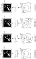
- Figures 6, 7, 8 and 9 show example operation of the trackball control 136 of Figures 3 , 4 and 5 .
- Figure 6 shows the sub-portion of the touch panel 130 with the trackball control 136 in connection with the console 112 and the display 122, which displays an image 602 and displays a graphical cursor 604 (e.g., an arrow in the illustrated embodiment) in a display region 606 of the display 122.
- a graphical cursor 604 e.g., an arrow in the illustrated embodiment
- a user 702 touches, with a finger 704, the generally flat, planar active surface 410.
- the touch screen user interface 128 conveys a signal to the console 112.
- the signal indicates a current location of the touch on the generally flat, planar active surface 410 of the trackball control 136.
- the controller maps the current finger position to a current location of the graphical cursor 604 on the image 602.
- the user 702 slides the finger 704 across the generally flat, planar active surface 410.
- the touch screen user interface 128 conveys a signal to the console 112.
- the signal indicates each new current location of the touch on the generally flat, planar active surface 410 of the trackball control 136.
- the controller 124 moves the graphical cursor 604 along a path 606 that corresponds to the movement of the finger cross the generally flat, planar active surface 410.
- Figure 9 the user 702 removes the finger 704 from the generally flat, planar active surface 410.
- Figure 9 shows the sub-portion of the touch panel 130 with the trackball control 136 in connection with the console 112 and the display 122, which displays the image 602 and the graphical cursor 604, at the new location, in the display region 606 of the display 122.
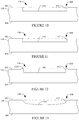
- Figures 10, 11, 12 and 13 show variations of the trackball control 136 of Figures 3 , 4 and 5 .
- the side wall 412 extends generally perpendicular between the first major surface 402 and the generally flat, planar active surface 410.
- the side wall 412 is a curved surface.
- the first major surface 402 and the side wall 412 meet at a region 1202 that is raised above first major surface 402.
- the side wall 412 is part of the first major surface 402, which includes a curved active region.
- Figures 14, 15 and 16 illustrate an example of the toggle control 138 ( Figure 1 ) implemented using the elliptical shaped control 208 and 210 ( Figure 2 ).
- Figure 14 shows a top down view of the toggle control 138 in connection with a sub-portion of the touch panel 130.
- Figure 15 shows a cross-sectional view of the toggle control 138 along lines A-A.
- Figure 16 shows a perspective view of the toggle control 138.
- the toggle control 138 has a first major surface 1402 and a second major surface 1404, which is parallel to and opposite from the first major surface 1402.
- the first and second major surfaces 1402 and 1404 are separated by a material of the touch panel 130.
- the first and second major surfaces 1402 and 1404 are separated are separated by a first non-zero distance 1406, which is in a range of 1 to 6 mm.
- the first major surface 1402 includes a first elliptical recess 1408.
- the first elliptical recess 1408 has a generally flat, planar active surface 1410 and a first side wall 1412, which extends from the first major surface 1402 to the generally flat, planar active surface 1410 within the touch panel 130.
- the generally flat, planar surface 1410 is offset from the first major surface 1402 by a second non-zero distance 1414, which is in a range of 0.1 to 0.5 mm and from the second major surface 1404 by a first non-zero distance 1416.
- the first elliptical recess 1408 has a first long axis 1418, which is in a range of 20 to 40 mm.
- the illustrated first side wall 1412 extends linearly from the first major surface 1402 to the first generally flat, planar surface 1410.
- the first side wall 1412 has a first length 1420, which is in a range of 0.1 to 2 mm. It is to be appreciated that the distances 1406, 1414, 1416, 1418, and 1420 are provided for explanatory purposes and are not limiting. Other ranges for these distances are contemplated herein.
- the first elliptical recess 1408 includes a second elliptical recess 1422.
- the second elliptical recess 1422 has a generally flat, planar actuating surface 1424 and a second side wall 1426, which extends from the generally flat, planar surface 1410 to the generally flat, planar actuating surface 1424 within the touch panel 130.
- the generally flat, planar actuating surface 1424 is offset from the generally flat, planar active surface 1410 by a third non-zero distance 1428, which is in a range of 0.1 to 0.5 mm, and from the second major surface 1404 by a fourth non-zero distance 1430.
- the second elliptical recess 1422 has a second long axis 1432, which is in a range of 2 to 30 mm.
- the illustrated second side wall 1426 extends linearly or non-linearly from the generally flat, planar active surface 1410 to the generally flat, planar actuating surface 1424.
- the second side wall 1426 has a second length 1434, which is in a range of 0.1 to 2 mm. It is to be appreciated that the distances 1428, 1430, 1432 and 1434, are provided for explanatory purposes and are not limiting. Other ranges for these distances are contemplated herein.
- At least one of the first or the second recesses 1408 or 1422 is circular, rectangular, square, and/or otherwise shaped.
- Figures 17, 18, 19 and 20 show example operation of the toggle control 138 of Figures 14, 15 and 16 .
- Figure 17 shows the sub-portion of the touch panel 130 with the toggle control 138 in connection with the console 112 and the display 122, which displays an image 1702 and a graphical indicia 1704 representing a numerical value in a display region 1706 of the display 122.
- the user 702 touches, with the finger 704, the generally flat, planar actuating surface 1422.
- the touch screen user interface 128 generates a control activation signal, which activates the generally flat, planar active surface 1410.
- the user 702 slides the finger 704 from the generally flat, planar actuating surface 1422 to the generally flat, planar active surface 1410.
- the controller increments the value 1704. In one instance, the controller increments the value 1704 again after a predetermined time delay from the previous increment where the finger 704 remains on the generally flat, planar active surface 1410.
- the controller increments the value 1704 again after a predetermined time delay from the previous increment in response to the user 702 removing the finger 704 and then touching the generally flat, planar active surface 1410 again.
- a combination and/or other gesture is used to increment the value 1704 again.
- the value 1704 is incremented twice as indicated by the two pluses ("++").
- the user 702 removes the finger 704 from the toggle control 138.
- the controller deactivates the generally flat, planar actuating surface 1422.
- the user 702 performs the above, but in the opposite direction as that shown in the Figures 17-20 . That is, in this embodiment, moving the finger 704 up the long axis increments the value 1704 and moving the finger 704 down the long axis decrements the value 1704. In a variation, moving the finger 704 up the long axis decrements the value 1704 and moving the finger 704 down the long axis increments the value 1704.
- moving the finger 704 perpendicular to the long axis does not change the value 1704.
- moving the finger 704 as described above increments and decrements the value 1704 in accordance with a first predetermined value (e.g., 1), and moving the finger 704 perpendicular to the long axis increments and decrements the value 1704 in accordance with a second different predetermined value (e.g., 5).
- transition between the first major surface 1402 to the generally flat, planar active surface 410 and/or between the generally flat, planar active surface 410 and the generally flat, planar actuating surface 422 can be as shown in Figure 10, 11, 12 and 13 and/or otherwise.
- the elliptical toggle control 138 of Figure 14-16 includes a double indentation, which provides a haptic input, thereby helping a user operate the elliptical toggle control 138 without looking at the touch panel 130.
- the lower level of the indentation is used to activate the upper level, which is used to manipulate the control.
- the elliptical toggle control 138 is configured as a focus bar
- the lower level is used to activate the upper level and to identify whether to increase or decrease the focus bar, and the upper level increases or decreases the size in response to the appropriate gesture.
- Figure 21 illustrates a method in accordance with the embodiments disclosed herein.
- a first physical contact with a touch control recessed in a surface of a touch screen user interface is sensed.
- a first signal indicative of the first physical contact is generated.
- a second signal indicative of the second physical contact is generated.
- a predetermined action is performed based on the first and second physical contact.
Landscapes
- Health & Medical Sciences (AREA)
- Life Sciences & Earth Sciences (AREA)
- Engineering & Computer Science (AREA)
- Physics & Mathematics (AREA)
- Medical Informatics (AREA)
- Animal Behavior & Ethology (AREA)
- Radiology & Medical Imaging (AREA)
- Nuclear Medicine, Radiotherapy & Molecular Imaging (AREA)
- Biomedical Technology (AREA)
- Heart & Thoracic Surgery (AREA)
- Biophysics (AREA)
- Molecular Biology (AREA)
- Surgery (AREA)
- Pathology (AREA)
- General Health & Medical Sciences (AREA)
- Public Health (AREA)
- Veterinary Medicine (AREA)
- General Engineering & Computer Science (AREA)
- Theoretical Computer Science (AREA)
- Human Computer Interaction (AREA)
- General Physics & Mathematics (AREA)
- Ultra Sonic Daignosis Equipment (AREA)
- Position Input By Displaying (AREA)
Description
- The following generally relates to an ultrasound imaging system and more particularly to an ultrasound imaging system touchscreen user interface.
- Ultrasound (US) imaging provides useful information about the interior characteristics (e.g., anatomical tissue, material flow, etc.) of a subject under examination. An ultrasound imaging system has included a probe with an ultrasound transducer array, a console, a display and a keyboard. The transducer array transmits an ultrasound signal into a field of view and receives echoes produced in response to the signal interacting with structure therein. The echoes are processed by the console, which generates images indicative of the structure that are visually presented in the display region.
- An example suitable keyboard has a coherent, flat surface, without any holes, e.g. glass, combined with a touch screen and e.g. a TFT panel. Unfortunately, such a keyboard is not well-suited for navigation on the surface of the keyboard by the user's hand to locate and use a control of interest of the keyboard without the user having to look at the keyboard. Exacerbating the problem, some controls will have more than one function or mode. Furthermore, such a keyboard is not well-suited making measurements, etc. with high precision.
-
US 2012/289828 A1 andUS 2013/261449 A1 each disclose an ultrasound imaging system according to the preamble of claims 1 and 5. - Aspects of the application address the above matters, and others.
- In one aspect, an ultrasound imaging system includes a probe with a transducer array with at least one transducer element. The ultrasound imaging system further includes a console with a controller, which controls the at least one transducer element, and an echo processor. The ultrasound imaging system further includes a display monitor. The ultrasound imaging system further includes a touch screen user interface, including: a touch panel with a first major surface and a first recess in the first major surface; and at least one touch sensitive control disposed in the recess. The first recess, comprises: a touch sensitive flat, planar surface configured for sensing a first gesture thereon which activates the touch sensitive flat, planar surface, and for sensing a subsequent gesture thereon that invokes a predetermined action of the at least one touch sensitive control.
- In another aspect, an ultrasound imaging system includes a probe with a transducer array with at least one transducer element. The ultrasound imaging system further includes a console with a controller, which controls the at least one transducer element, and an echo processor. The ultrasound imaging system further includes a display monitor. The ultrasound imaging system further includes a touch screen user interface, including: a touch panel with a first major surface and a first recess in the first major surface; and at least one touch sensitive control disposed in the recess. The first recess, comprises: a second recess disposed therein, and a touch sensitive flat, actuating planar surface, the second recess, comprising a touch sensitive flat, active planar surface, wherein the touch sensitive flat, actuating planar surface senses a first gesture thereon, which activates the touch sensitive flat, active planar surface.
- Those skilled in the art will recognize still other aspects of the present application upon reading and understanding the attached description.
- The application is illustrated by way of example and not limitation in the figures of the accompanying drawings, in which like references indicate similar elements and in which:
-
Figure 1 schematically illustrates an example imaging system with a touchscreen control user interface; -
Figure 2 schematically illustrates an example touch panel of the touchscreen control user interface; -
Figure 3 schematically illustrates a top down view of an example trackball touch control of an active region of the panel of the touchscreen control user interface; -
Figure 4 schematically illustrates a cross-sectional view of the example trackball touch control ofFigure 3 ; -
Figure 5 schematically illustrates a perspective view of the example trackball touch control ofFigure 3 ; -
Figures 6-9 illustrates example operation of the example trackball touch control ofFigure 4 ; -
Figures 10-13 illustrates variations of the example trackball touch control ofFigures 4 and14 ; -
Figure 14 schematically illustrates a top down view of an example toggle touch control of the active region of the panel of the touchscreen control user interface; -
Figure 15 schematically illustrates a cross-sectional view of the example toggle touch control ofFigure 14 ; -
Figure 16 schematically illustrates a perspective view of the example toggle touch control ofFigure 14 ; -
Figures 17-20 illustrates example operation of the example toggle touch control ofFigure 14 ; and -
Figure 21 illustrates an example method in accordance with the embodiments disclosed herein. -
Figure 1 schematically illustrates an ultrasound (US)imaging system 102. Theultrasound imaging system 102 includes aprobe 104 with a one-dimensional (ID) or two-dimensional (2D)transducer array 106 with at least onetransducer element 108. The at least onetransducer element 108 is configured to transmit ultrasound signals and receive echo signals. Suitable array configurations include, but are not limited to, linear, curved (e.g., concave, convex, etc.), circular, etc., full populated or sparse, etc. - The
ultrasound imaging system 102 further includes aconsole 112. Theconsole 112 includes transmitcircuitry 114 that selectively excites one or more of the at least onetransducer element 108. More particularly, thetransmit circuitry 114 generates a set of pulses (or a pulsed signal) that are conveyed to thetransducer array 106. The set of pulses excites the at least onetransducer element 108, causing the at least onetransducer element 108 to transmit an ultrasound signal into an examination scan field of view. - The
console 112 further includes receivecircuitry 116 that receives a set of echoes (or echo signals) generated in response to the transmitted ultrasound signals. The echoes, generally, are a result of the interaction between the emitted ultrasound signals and the object (e.g., flowing blood cells, organ cells, etc.) in the scan field of view. Thereceive circuit 116 may be configured for spatial compounding, filtering (e.g., FIR and/or IIR), and/or other echo processing. - The
console 112 further includes an echo processor (e.g., a beamformer) 118 that processes the received echoes. For example, in B-mode, this may include applying time delays and weights to the echoes and summing the delayed and weighted echoes, and generating an image. Theconsole 112 further includes ascan converter 120 that scan converts the processed data for display, e.g., by converting the beamformed data to the coordinate system of a display monitor used to visually present the processed data. - The
console 112 further includes acontroller 124 that controls the various components of thesystem 102. For example, such control may include controlling thetransmit circuitry 114 to excite individual or groups of the at least onetransducer element 108 for an A-mode, B-mode, C-plane, and/or other data acquisition mode, steering and/or focusing the transmitted signal, etc., actuating the at least onetransducer element 108 for steering and/or focusing the received echoes, etc. - The
ultrasound imaging system 102 further includes adisplay monitor 122. Thedisplay monitor 122 can be a cathode ray tube (CRT), a liquid crystal display (LCD), a light emitting diode (LED), and/or other display monitor. Thedisplay monitor 122 includes a display region, which can visually present images and/or flow information generated by theconsole 112. - The
system 102 further includes a touchscreen user interface 128 with atouch panel 130. Thetouch panel 130 includes a resistive, a capacitive, an acoustic, an infrared, an optical, a piezoelectric, and/or other region. Thetouch panel 130 includes an active region(s) 132 with a touch sensitive control(s) 134. A touch sensitive control(s) 134 is actuated by a gesture (e.g., a press, a swipe, a touch, etc.) on the touch sensitive control(s) 134 with one or more fingers, a stylus, a glove, etc. - Examples of the touch sensitive control(s) 134 include a
trackball control 136 for navigating a graphical pointer displayed in the display region of thedisplay monitor 122, atoggle control 138 for incrementing and decrementing value corresponding to focus, depth, zoom, etc. and/or other control(s) 140. Briefly turning toFigure 2 , an example of the touchscreen user interface 128 with a plurality of the touch sensitive control(s) 134 is illustrated. - In
Figure 2 , the touch sensitive control(s) 134 include circular shapedcontrols controls 202 have a first size (i.e., diameter), and thecontrol 204 has a second size, which is larger than the first size. In a variation, the touch sensitive control(s) 134 include only a single size circular control or more than two sizes of circular controls. Furthermore, the illustrated number of the circular shapedcontrols circular controls - The touch sensitive control(s) 134 also include rectangular shaped
controls 206 in which the rectangular shapedcontrols 206 include curved sides and rounded corners. In this example, the rectangular shapedcontrols 206 are the same size. However, in a variation, the touch sensitive control(s) 134 include multiple different size rectangular shaped controls 206. Furthermore, the illustrated number of the rectangular shapedcontrols 206 is not limiting; in a variation, there could be more or less of thecircular controls - The touch sensitive control(s) 134 also include oval or elliptical shaped
controls controls controls controls controls - Returning to
Figure 1 , thetouch panel 130 may also include one or more non-active regions, a display such as a LCD, a thin film transistor (TFT) LCD, an organic light-emitting diode (OLED) and/or other display, and/or other features. Another example of a suitable interface is described inUS patent application serial number 13/748,653 -
Figures 3 ,4 and 5 illustrate an example of the trackball control 136 (Figure 1 ) implemented using the larger circular shaped control 204 (Figure 2). Figure 3 shows a top down view of thetrackball control 136 in connection with a sub-portion of thetouch panel 130.Figure 4 shows a cross-sectional view of thetrackball control 136 along lines A-A.Figure 5 shows a perspective view of thetrackball control 136. - With reference to
figures 3 ,4 and 5 , thetrackball control 136 has a firstmajor surface 402 and a secondmajor surface 404, which is parallel to and opposite from the firstmajor surface 402. The first and secondmajor surfaces touch panel 130. In the illustrated embodiment, the first and secondmajor surfaces non-zero distance 406, which is in a range of 1 to 6 millimeters (mm). - The first
major surface 402 includes arecess 408. The recess has a generally flat, planaractive surface 410 and aside wall 412, which extends from the firstmajor surface 402 to the generally flat, planaractive surface 410 within thetouch panel 130. The generally flat,planar surface 410 is offset from the firstmajor surface 402 by anon-zero distance 414, which is in a range of 0.1 to 1 mm. - The
recess 408 has adiameter 418, which is in a range of 40 to 100 mm. The illustratedside wall 412 extends linearly or non-linearly from the firstmajor surface 402 to therecess 408. Theside wall 412 has alength 420, which is in a range of 0.1 to 4 mm. It is to be appreciated that thedistances - The
circular trackball control 136 inFigure 3-5 resembles a trackball and thereby is easily recognized by ultrasound users. Configured to provide trackball functionality, thecircular trackball control 136 can be used to control a cursor on the ultrasound image with higher accuracy compared to managing the ultrasound image with direct touch input. Using thecircular trackball control 136 as such, thecircular trackball control 136 can be used to make measurements, etc. with high precision. -
Figures 6, 7, 8 and 9 show example operation of thetrackball control 136 ofFigures 3 ,4 and5 .Figure 6 shows the sub-portion of thetouch panel 130 with thetrackball control 136 in connection with theconsole 112 and thedisplay 122, which displays animage 602 and displays a graphical cursor 604 (e.g., an arrow in the illustrated embodiment) in adisplay region 606 of thedisplay 122. - In
Figure 7 , auser 702 touches, with afinger 704, the generally flat, planaractive surface 410. In response thereto, the touchscreen user interface 128 conveys a signal to theconsole 112. The signal indicates a current location of the touch on the generally flat, planaractive surface 410 of thetrackball control 136. The controller maps the current finger position to a current location of thegraphical cursor 604 on theimage 602. - In
Figure 8 , theuser 702 slides thefinger 704 across the generally flat, planaractive surface 410. As the finger slides, the touchscreen user interface 128 conveys a signal to theconsole 112. The signal indicates each new current location of the touch on the generally flat, planaractive surface 410 of thetrackball control 136. Thecontroller 124 moves thegraphical cursor 604 along apath 606 that corresponds to the movement of the finger cross the generally flat, planaractive surface 410. - In
Figure 9 , theuser 702 removes thefinger 704 from the generally flat, planaractive surface 410.Figure 9 shows the sub-portion of thetouch panel 130 with thetrackball control 136 in connection with theconsole 112 and thedisplay 122, which displays theimage 602 and thegraphical cursor 604, at the new location, in thedisplay region 606 of thedisplay 122. -
Figures 10, 11, 12 and 13 show variations of thetrackball control 136 ofFigures 3 ,4 and 5 . InFigure 10 , theside wall 412 extends generally perpendicular between the firstmajor surface 402 and the generally flat, planaractive surface 410. InFigure 10 , theside wall 412 is a curved surface. InFigure 12 , the firstmajor surface 402 and theside wall 412 meet at aregion 1202 that is raised above firstmajor surface 402. InFigure 13 , theside wall 412 is part of the firstmajor surface 402, which includes a curved active region. -
Figures 14, 15 and 16 illustrate an example of the toggle control 138 (Figure 1 ) implemented using the elliptical shapedcontrol 208 and 210 (Figure 2 ).Figure 14 shows a top down view of thetoggle control 138 in connection with a sub-portion of thetouch panel 130.Figure 15 shows a cross-sectional view of thetoggle control 138 along lines A-A.Figure 16 shows a perspective view of thetoggle control 138. - The
toggle control 138 has a firstmajor surface 1402 and a secondmajor surface 1404, which is parallel to and opposite from the firstmajor surface 1402. The first and secondmajor surfaces touch panel 130. In the illustrated embodiment, the first and secondmajor surfaces non-zero distance 1406, which is in a range of 1 to 6 mm. - The first
major surface 1402 includes a firstelliptical recess 1408. The firstelliptical recess 1408 has a generally flat, planaractive surface 1410 and afirst side wall 1412, which extends from the firstmajor surface 1402 to the generally flat, planaractive surface 1410 within thetouch panel 130. The generally flat,planar surface 1410 is offset from the firstmajor surface 1402 by a secondnon-zero distance 1414, which is in a range of 0.1 to 0.5 mm and from the secondmajor surface 1404 by a firstnon-zero distance 1416. - The first
elliptical recess 1408 has a firstlong axis 1418, which is in a range of 20 to 40 mm. The illustratedfirst side wall 1412 extends linearly from the firstmajor surface 1402 to the first generally flat,planar surface 1410. Thefirst side wall 1412 has afirst length 1420, which is in a range of 0.1 to 2 mm. It is to be appreciated that thedistances - The first
elliptical recess 1408 includes a secondelliptical recess 1422. The secondelliptical recess 1422 has a generally flat,planar actuating surface 1424 and asecond side wall 1426, which extends from the generally flat,planar surface 1410 to the generally flat,planar actuating surface 1424 within thetouch panel 130. The generally flat,planar actuating surface 1424 is offset from the generally flat, planaractive surface 1410 by a thirdnon-zero distance 1428, which is in a range of 0.1 to 0.5 mm, and from the secondmajor surface 1404 by a fourthnon-zero distance 1430. - The second
elliptical recess 1422 has a secondlong axis 1432, which is in a range of 2 to 30 mm. The illustratedsecond side wall 1426 extends linearly or non-linearly from the generally flat, planaractive surface 1410 to the generally flat,planar actuating surface 1424. Thesecond side wall 1426 has asecond length 1434, which is in a range of 0.1 to 2 mm. It is to be appreciated that thedistances - In a variation, at least one of the first or the
second recesses -
Figures 17, 18, 19 and 20 show example operation of thetoggle control 138 ofFigures 14, 15 and 16 .Figure 17 shows the sub-portion of thetouch panel 130 with thetoggle control 138 in connection with theconsole 112 and thedisplay 122, which displays animage 1702 and agraphical indicia 1704 representing a numerical value in adisplay region 1706 of thedisplay 122. - In
Figure 18 , theuser 702 touches, with thefinger 704, the generally flat,planar actuating surface 1422. In response thereto, the touchscreen user interface 128 generates a control activation signal, which activates the generally flat, planaractive surface 1410. - In
Figure 19 , theuser 702 slides thefinger 704 from the generally flat,planar actuating surface 1422 to the generally flat, planaractive surface 1410. In response to thefinger 704 being on the generally flat, planaractive surface 1410, the controller increments thevalue 1704. In one instance, the controller increments thevalue 1704 again after a predetermined time delay from the previous increment where thefinger 704 remains on the generally flat, planaractive surface 1410. - In another instance, the controller increments the
value 1704 again after a predetermined time delay from the previous increment in response to theuser 702 removing thefinger 704 and then touching the generally flat, planaractive surface 1410 again. In another instance, a combination and/or other gesture is used to increment thevalue 1704 again. In the illustrated embodiment, thevalue 1704 is incremented twice as indicated by the two pluses ("++"). - In
Figure 20 , theuser 702 removes thefinger 704 from thetoggle control 138. In response to a predetermined time delay from the removal of thefinger 704, the controller deactivates the generally flat,planar actuating surface 1422. - To decrement the
value 1704, theuser 702 performs the above, but in the opposite direction as that shown in theFigures 17-20 . That is, in this embodiment, moving thefinger 704 up the long axis increments thevalue 1704 and moving thefinger 704 down the long axis decrements thevalue 1704. In a variation, moving thefinger 704 up the long axis decrements thevalue 1704 and moving thefinger 704 down the long axis increments thevalue 1704. - In the illustrated embodiment, moving the
finger 704 perpendicular to the long axis does not change thevalue 1704. In a variation, moving thefinger 704 as described above increments and decrements thevalue 1704 in accordance with a first predetermined value (e.g., 1), and moving thefinger 704 perpendicular to the long axis increments and decrements thevalue 1704 in accordance with a second different predetermined value (e.g., 5). - Similar to the
trackball control 136, the transition between the firstmajor surface 1402 to the generally flat, planaractive surface 410 and/or between the generally flat, planaractive surface 410 and the generally flat, planar actuating surface 422 can be as shown inFigure 10, 11, 12 and 13 and/or otherwise. - Generally, the
elliptical toggle control 138 ofFigure 14-16 includes a double indentation, which provides a haptic input, thereby helping a user operate theelliptical toggle control 138 without looking at thetouch panel 130. The lower level of the indentation is used to activate the upper level, which is used to manipulate the control. Where theelliptical toggle control 138 is configured as a focus bar, the lower level is used to activate the upper level and to identify whether to increase or decrease the focus bar, and the upper level increases or decreases the size in response to the appropriate gesture. -
Figure 21 illustrates a method in accordance with the embodiments disclosed herein. - It is to be appreciated that the order of the following acts is provided for explanatory purposes and is not limiting. As such, one or more of the following acts may occur in a different order. Furthermore, one or more of the following acts may be omitted and/or one or more additional acts may be added.
- At 2102, a first physical contact with a touch control recessed in a surface of a touch screen user interface is sensed.
- At 2104, a first signal indicative of the first physical contact is generated.
- At 2106, a second different physical contact with the touch control recessed in the surface of the touch screen user interface is sensed; and
- At 2108, a second signal indicative of the second physical contact is generated.
- At 2110, a predetermined action is performed based on the first and second physical contact.
- The application has been described with reference to various embodiments. Modifications and alterations will occur to others upon reading the application. It is intended that the invention be construed as including all such modifications and alterations, including insofar as they come within the scope of the appended claims.
Claims (11)
- An ultrasound imaging system (102), comprising:a probe (104), including: a transducer array (106) with at least one transducer element (108);a console (112), including: a controller (124) configured for controlling the at least one transducer element; and an echo processor;a display monitor (122); anda touch screen user interface (128), including: a touch panel (130) with a first major surface (402, 1402) and a first recess (408, 1408) in the first major surface; and at least one touch sensitive control (134) disposed in the first recess,characterized in that the first recess, comprises: a touch sensitive flat, planar surface (410) configured for sensing a first gesture thereon which activates the touch sensitive flat, planar surface, and for sensing a subsequent gesture thereon that invokes a predetermined action of the at least one touch sensitive control.
- The ultrasound imaging system of claim 1, wherein the at least one touch sensitive control is circular in shape.
- The ultrasound imaging system of claim 2, wherein the at least one touch sensitive control has a diameter in a range of 40 to 100 mm and a depth in a range of 0.1 to 1 mm.
- The ultrasound imaging system of claim 1, wherein the at least one touch sensitive control is a touch sensitive trackball, and wherein a third gesture causes the touch sensitive control to move a graphical pointer displayed via the display in coordination with the third gesture.
- An ultrasound imaging system (102), comprising:a probe (104), including: a transducer array (106) with at least one transducer element (108);a console (112), including: a controller (124) configured for controlling the at least one transducer element; and an echo processor;a display monitor (122); anda touch screen user interface (128), including: a touch panel (130) with a first major surface (402, 1402) and a first recess (408, 1408) in the first major surface; and at least one touch sensitive control (134) disposed in the first recess,characterized in that the first recess, comprises: a second recess (1422) disposed therein, and a touch sensitive flat, actuating planar surface (1410), the second recess, comprising a touch sensitive flat, active planar surface (1424), wherein the touch sensitive flat, actuating planar surface is configured for sensing a first gesture thereon, which activates the touch sensitive flat, active planar surface (1424).
- The ultrasound imaging system of claim 5, wherein the at least one touch sensitive control is elliptical in shape.
- The ultrasound imaging system of claim 6, wherein the first recess has a first long axis in a range of 20 to 40 mm and a first depth in a range of 0.1 to 0.5 mm.
- The ultrasound imaging system of claim 5, wherein the second recess is elliptical in shape.
- The ultrasound imaging system of any of claims 5 to 8, wherein the second recess has a second long axis in a range of 20 to 30 mm and a second depth in a range of 0.1 to 0.5 mm.
- The ultrasound imaging system of any of claims 5 to 9, wherein moving the first gesture from the touch sensitive flat, actuating planar surface to the touch sensitive flat, active planar surface invokes a predetermined action of the at least one touch sensitive control.
- The ultrasound imaging system of claim 10, wherein the at least one touch sensitive control is toggle control, and wherein moving the first gesture in one direction from the touch sensitive flat, actuating planar surface to the touch sensitive flat, active planar surface increments a control parameter and moving the first gesture in an opposite direction from the touch sensitive flat, actuating planar surface to the touch sensitive flat, active planar surface decrements the control parameter.
Applications Claiming Priority (1)
| Application Number | Priority Date | Filing Date | Title |
|---|---|---|---|
| PCT/IB2014/060237 WO2015145213A1 (en) | 2014-03-27 | 2014-03-27 | Ultrasound imaging system touchscreen user interface |
Publications (2)
| Publication Number | Publication Date |
|---|---|
| EP3122257A1 EP3122257A1 (en) | 2017-02-01 |
| EP3122257B1 true EP3122257B1 (en) | 2021-02-17 |
Family
ID=50733100
Family Applications (1)
| Application Number | Title | Priority Date | Filing Date |
|---|---|---|---|
| EP14724791.0A Active EP3122257B1 (en) | 2014-03-27 | 2014-03-27 | Ultrasound imaging system touchscreen user interface |
Country Status (4)
| Country | Link |
|---|---|
| US (1) | US20170119353A1 (en) |
| EP (1) | EP3122257B1 (en) |
| CN (1) | CN106456106B (en) |
| WO (1) | WO2015145213A1 (en) |
Families Citing this family (4)
| Publication number | Priority date | Publication date | Assignee | Title |
|---|---|---|---|---|
| JP6392600B2 (en) * | 2014-09-12 | 2018-09-19 | 古野電気株式会社 | Operating device and cursor movement control method |
| EP3622528A1 (en) * | 2017-05-09 | 2020-03-18 | Boston Scientific Scimed, Inc. | Operating room devices, methods, and systems |
| JP7447494B2 (en) * | 2020-01-08 | 2024-03-12 | 富士フイルムビジネスイノベーション株式会社 | Display device and display control program |
| JP7384107B2 (en) * | 2020-04-20 | 2023-11-21 | コニカミノルタ株式会社 | Operation input device and ultrasound diagnostic device |
Family Cites Families (8)
| Publication number | Priority date | Publication date | Assignee | Title |
|---|---|---|---|---|
| US20020173721A1 (en) * | 1999-08-20 | 2002-11-21 | Novasonics, Inc. | User interface for handheld imaging devices |
| US20040004559A1 (en) * | 2002-07-01 | 2004-01-08 | Rast Rodger H. | Keyboard device with preselect feedback |
| US8684900B2 (en) * | 2006-05-16 | 2014-04-01 | Bao Tran | Health monitoring appliance |
| CN101498984B (en) * | 2008-02-01 | 2011-07-13 | 致伸科技股份有限公司 | Computer cursor control system and method for controlling cursor movement |
| US9119586B2 (en) * | 2011-05-12 | 2015-09-01 | B-K Medical Aps | Ultrasound imaging system |
| JP5907780B2 (en) * | 2012-04-02 | 2016-04-26 | 富士フイルム株式会社 | Ultrasonic diagnostic equipment |
| US9414810B2 (en) * | 2013-01-24 | 2016-08-16 | B-K Medical Aps | Ultrasound imaging system |
| TWI710356B (en) * | 2013-09-25 | 2020-11-21 | 美商德拉工業公司 | Tablet ultrasound system |
-
2014
- 2014-03-27 US US15/129,533 patent/US20170119353A1/en not_active Abandoned
- 2014-03-27 WO PCT/IB2014/060237 patent/WO2015145213A1/en not_active Ceased
- 2014-03-27 EP EP14724791.0A patent/EP3122257B1/en active Active
- 2014-03-27 CN CN201480077511.1A patent/CN106456106B/en active Active
Non-Patent Citations (1)
| Title |
|---|
| None * |
Also Published As
| Publication number | Publication date |
|---|---|
| WO2015145213A1 (en) | 2015-10-01 |
| US20170119353A1 (en) | 2017-05-04 |
| EP3122257A1 (en) | 2017-02-01 |
| CN106456106A (en) | 2017-02-22 |
| CN106456106B (en) | 2023-04-18 |
Similar Documents
| Publication | Publication Date | Title |
|---|---|---|
| US8827909B2 (en) | Ultrasound probe | |
| JP5615270B2 (en) | Object positioning | |
| KR101534089B1 (en) | Ultrasonic diagnostic apparatus and operating method for the same | |
| CN106462657B (en) | Graphical virtual control for an ultrasound imaging system | |
| EP2742868A1 (en) | Ultrasound apparatus and method of inputting information into same | |
| EP3888557B1 (en) | Ultrasonic diagnostic device and method for controlling ultrasonic diagnostic device | |
| EP2254033A1 (en) | Ultrasound diagnosis apparatus using touch interaction | |
| JP2010131396A (en) | Portable ultrasound system | |
| WO2014058929A1 (en) | Systems and methods for touch-based input on ultrasound devices | |
| EP3431008A1 (en) | Ultrasound diagnostic apparatus and operating method thereof | |
| EP2926737B1 (en) | Ultrasound diagnostic apparatus and method of operating the same | |
| EP3199251A1 (en) | Ultrasonic transducer and ultrasonic probe including the same | |
| US20170119353A1 (en) | Ultrasound imaging system touchscreen user interface | |
| US11036376B2 (en) | Ultrasound diagnosis apparatus and method of controlling ultrasound diagnosis apparatus | |
| EP2848200A1 (en) | Method and Apparatus for Providing Ultrasound Information By Using Guidelines | |
| US20160113625A1 (en) | Ultrasonic diagnostic apparatus and method therefor | |
| US11801038B2 (en) | Ultrasound imaging system touch panel with multiple different clusters of controls | |
| EP3047917A1 (en) | Matching member and ultrasound probe including the same | |
| US20200187908A1 (en) | Method and systems for touchscreen user interface controls | |
| US9414810B2 (en) | Ultrasound imaging system | |
| KR101534090B1 (en) | Ultrasound apparatus and method for inputting information using the ultrasound apparatus | |
| EP2829966A1 (en) | Hardware device, user control apparatus for the same, medical apparatus including the same, and method of operating medical apparatus | |
| KR20150024173A (en) | Ultrasonic apparatus for measuring stiffness of carotid artery and measuring method for the same | |
| Chiu et al. | Implementation of ultrasonic touchless interactive panel using the polymer-based CMUT array | |
| KR102190028B1 (en) | Method for setting a focusing point, apparatus for setting a focusing point and ultrasonic imaging apparatus |
Legal Events
| Date | Code | Title | Description |
|---|---|---|---|
| PUAI | Public reference made under article 153(3) epc to a published international application that has entered the european phase |
Free format text: ORIGINAL CODE: 0009012 |
|
| STAA | Information on the status of an ep patent application or granted ep patent |
Free format text: STATUS: REQUEST FOR EXAMINATION WAS MADE |
|
| 17P | Request for examination filed |
Effective date: 20160928 |
|
| AK | Designated contracting states |
Kind code of ref document: A1 Designated state(s): AL AT BE BG CH CY CZ DE DK EE ES FI FR GB GR HR HU IE IS IT LI LT LU LV MC MK MT NL NO PL PT RO RS SE SI SK SM TR |
|
| AX | Request for extension of the european patent |
Extension state: BA ME |
|
| DAX | Request for extension of the european patent (deleted) | ||
| STAA | Information on the status of an ep patent application or granted ep patent |
Free format text: STATUS: EXAMINATION IS IN PROGRESS |
|
| 17Q | First examination report despatched |
Effective date: 20200402 |
|
| GRAP | Despatch of communication of intention to grant a patent |
Free format text: ORIGINAL CODE: EPIDOSNIGR1 |
|
| STAA | Information on the status of an ep patent application or granted ep patent |
Free format text: STATUS: GRANT OF PATENT IS INTENDED |
|
| INTG | Intention to grant announced |
Effective date: 20200925 |
|
| RIC1 | Information provided on ipc code assigned before grant |
Ipc: A61B 8/00 20060101AFI20200911BHEP Ipc: G06F 3/041 20060101ALN20200911BHEP |
|
| GRAS | Grant fee paid |
Free format text: ORIGINAL CODE: EPIDOSNIGR3 |
|
| GRAA | (expected) grant |
Free format text: ORIGINAL CODE: 0009210 |
|
| STAA | Information on the status of an ep patent application or granted ep patent |
Free format text: STATUS: THE PATENT HAS BEEN GRANTED |
|
| AK | Designated contracting states |
Kind code of ref document: B1 Designated state(s): AL AT BE BG CH CY CZ DE DK EE ES FI FR GB GR HR HU IE IS IT LI LT LU LV MC MK MT NL NO PL PT RO RS SE SI SK SM TR |
|
| REG | Reference to a national code |
Ref country code: GB Ref legal event code: FG4D |
|
| REG | Reference to a national code |
Ref country code: CH Ref legal event code: EP |
|
| REG | Reference to a national code |
Ref country code: DE Ref legal event code: R096 Ref document number: 602014074823 Country of ref document: DE |
|
| REG | Reference to a national code |
Ref country code: AT Ref legal event code: REF Ref document number: 1360403 Country of ref document: AT Kind code of ref document: T Effective date: 20210315 |
|
| REG | Reference to a national code |
Ref country code: IE Ref legal event code: FG4D |
|
| REG | Reference to a national code |
Ref country code: LT Ref legal event code: MG9D |
|
| REG | Reference to a national code |
Ref country code: NL Ref legal event code: MP Effective date: 20210217 |
|
| PG25 | Lapsed in a contracting state [announced via postgrant information from national office to epo] |
Ref country code: PT Free format text: LAPSE BECAUSE OF FAILURE TO SUBMIT A TRANSLATION OF THE DESCRIPTION OR TO PAY THE FEE WITHIN THE PRESCRIBED TIME-LIMIT Effective date: 20210617 Ref country code: LT Free format text: LAPSE BECAUSE OF FAILURE TO SUBMIT A TRANSLATION OF THE DESCRIPTION OR TO PAY THE FEE WITHIN THE PRESCRIBED TIME-LIMIT Effective date: 20210217 Ref country code: FI Free format text: LAPSE BECAUSE OF FAILURE TO SUBMIT A TRANSLATION OF THE DESCRIPTION OR TO PAY THE FEE WITHIN THE PRESCRIBED TIME-LIMIT Effective date: 20210217 Ref country code: HR Free format text: LAPSE BECAUSE OF FAILURE TO SUBMIT A TRANSLATION OF THE DESCRIPTION OR TO PAY THE FEE WITHIN THE PRESCRIBED TIME-LIMIT Effective date: 20210217 Ref country code: GR Free format text: LAPSE BECAUSE OF FAILURE TO SUBMIT A TRANSLATION OF THE DESCRIPTION OR TO PAY THE FEE WITHIN THE PRESCRIBED TIME-LIMIT Effective date: 20210518 Ref country code: BG Free format text: LAPSE BECAUSE OF FAILURE TO SUBMIT A TRANSLATION OF THE DESCRIPTION OR TO PAY THE FEE WITHIN THE PRESCRIBED TIME-LIMIT Effective date: 20210517 Ref country code: NO Free format text: LAPSE BECAUSE OF FAILURE TO SUBMIT A TRANSLATION OF THE DESCRIPTION OR TO PAY THE FEE WITHIN THE PRESCRIBED TIME-LIMIT Effective date: 20210517 |
|
| REG | Reference to a national code |
Ref country code: AT Ref legal event code: MK05 Ref document number: 1360403 Country of ref document: AT Kind code of ref document: T Effective date: 20210217 |
|
| PG25 | Lapsed in a contracting state [announced via postgrant information from national office to epo] |
Ref country code: NL Free format text: LAPSE BECAUSE OF FAILURE TO SUBMIT A TRANSLATION OF THE DESCRIPTION OR TO PAY THE FEE WITHIN THE PRESCRIBED TIME-LIMIT Effective date: 20210217 Ref country code: LV Free format text: LAPSE BECAUSE OF FAILURE TO SUBMIT A TRANSLATION OF THE DESCRIPTION OR TO PAY THE FEE WITHIN THE PRESCRIBED TIME-LIMIT Effective date: 20210217 Ref country code: PL Free format text: LAPSE BECAUSE OF FAILURE TO SUBMIT A TRANSLATION OF THE DESCRIPTION OR TO PAY THE FEE WITHIN THE PRESCRIBED TIME-LIMIT Effective date: 20210217 Ref country code: RS Free format text: LAPSE BECAUSE OF FAILURE TO SUBMIT A TRANSLATION OF THE DESCRIPTION OR TO PAY THE FEE WITHIN THE PRESCRIBED TIME-LIMIT Effective date: 20210217 Ref country code: SE Free format text: LAPSE BECAUSE OF FAILURE TO SUBMIT A TRANSLATION OF THE DESCRIPTION OR TO PAY THE FEE WITHIN THE PRESCRIBED TIME-LIMIT Effective date: 20210217 |
|
| PG25 | Lapsed in a contracting state [announced via postgrant information from national office to epo] |
Ref country code: IS Free format text: LAPSE BECAUSE OF FAILURE TO SUBMIT A TRANSLATION OF THE DESCRIPTION OR TO PAY THE FEE WITHIN THE PRESCRIBED TIME-LIMIT Effective date: 20210617 |
|
| PG25 | Lapsed in a contracting state [announced via postgrant information from national office to epo] |
Ref country code: SM Free format text: LAPSE BECAUSE OF FAILURE TO SUBMIT A TRANSLATION OF THE DESCRIPTION OR TO PAY THE FEE WITHIN THE PRESCRIBED TIME-LIMIT Effective date: 20210217 Ref country code: CZ Free format text: LAPSE BECAUSE OF FAILURE TO SUBMIT A TRANSLATION OF THE DESCRIPTION OR TO PAY THE FEE WITHIN THE PRESCRIBED TIME-LIMIT Effective date: 20210217 Ref country code: EE Free format text: LAPSE BECAUSE OF FAILURE TO SUBMIT A TRANSLATION OF THE DESCRIPTION OR TO PAY THE FEE WITHIN THE PRESCRIBED TIME-LIMIT Effective date: 20210217 Ref country code: AT Free format text: LAPSE BECAUSE OF FAILURE TO SUBMIT A TRANSLATION OF THE DESCRIPTION OR TO PAY THE FEE WITHIN THE PRESCRIBED TIME-LIMIT Effective date: 20210217 |
|
| REG | Reference to a national code |
Ref country code: CH Ref legal event code: PL |
|
| REG | Reference to a national code |
Ref country code: DE Ref legal event code: R097 Ref document number: 602014074823 Country of ref document: DE |
|
| PG25 | Lapsed in a contracting state [announced via postgrant information from national office to epo] |
Ref country code: MC Free format text: LAPSE BECAUSE OF FAILURE TO SUBMIT A TRANSLATION OF THE DESCRIPTION OR TO PAY THE FEE WITHIN THE PRESCRIBED TIME-LIMIT Effective date: 20210217 Ref country code: DK Free format text: LAPSE BECAUSE OF FAILURE TO SUBMIT A TRANSLATION OF THE DESCRIPTION OR TO PAY THE FEE WITHIN THE PRESCRIBED TIME-LIMIT Effective date: 20210217 Ref country code: ES Free format text: LAPSE BECAUSE OF FAILURE TO SUBMIT A TRANSLATION OF THE DESCRIPTION OR TO PAY THE FEE WITHIN THE PRESCRIBED TIME-LIMIT Effective date: 20210217 Ref country code: SK Free format text: LAPSE BECAUSE OF FAILURE TO SUBMIT A TRANSLATION OF THE DESCRIPTION OR TO PAY THE FEE WITHIN THE PRESCRIBED TIME-LIMIT Effective date: 20210217 Ref country code: RO Free format text: LAPSE BECAUSE OF FAILURE TO SUBMIT A TRANSLATION OF THE DESCRIPTION OR TO PAY THE FEE WITHIN THE PRESCRIBED TIME-LIMIT Effective date: 20210217 |
|
| REG | Reference to a national code |
Ref country code: BE Ref legal event code: MM Effective date: 20210331 |
|
| PLBE | No opposition filed within time limit |
Free format text: ORIGINAL CODE: 0009261 |
|
| STAA | Information on the status of an ep patent application or granted ep patent |
Free format text: STATUS: NO OPPOSITION FILED WITHIN TIME LIMIT |
|
| 26N | No opposition filed |
Effective date: 20211118 |
|
| GBPC | Gb: european patent ceased through non-payment of renewal fee |
Effective date: 20210517 |
|
| PG25 | Lapsed in a contracting state [announced via postgrant information from national office to epo] |
Ref country code: CH Free format text: LAPSE BECAUSE OF NON-PAYMENT OF DUE FEES Effective date: 20210331 Ref country code: AL Free format text: LAPSE BECAUSE OF FAILURE TO SUBMIT A TRANSLATION OF THE DESCRIPTION OR TO PAY THE FEE WITHIN THE PRESCRIBED TIME-LIMIT Effective date: 20210217 Ref country code: LI Free format text: LAPSE BECAUSE OF NON-PAYMENT OF DUE FEES Effective date: 20210331 Ref country code: LU Free format text: LAPSE BECAUSE OF NON-PAYMENT OF DUE FEES Effective date: 20210327 Ref country code: FR Free format text: LAPSE BECAUSE OF NON-PAYMENT OF DUE FEES Effective date: 20210417 Ref country code: IE Free format text: LAPSE BECAUSE OF NON-PAYMENT OF DUE FEES Effective date: 20210327 |
|
| PG25 | Lapsed in a contracting state [announced via postgrant information from national office to epo] |
Ref country code: SI Free format text: LAPSE BECAUSE OF FAILURE TO SUBMIT A TRANSLATION OF THE DESCRIPTION OR TO PAY THE FEE WITHIN THE PRESCRIBED TIME-LIMIT Effective date: 20210217 |
|
| PG25 | Lapsed in a contracting state [announced via postgrant information from national office to epo] |
Ref country code: IT Free format text: LAPSE BECAUSE OF FAILURE TO SUBMIT A TRANSLATION OF THE DESCRIPTION OR TO PAY THE FEE WITHIN THE PRESCRIBED TIME-LIMIT Effective date: 20210217 Ref country code: GB Free format text: LAPSE BECAUSE OF NON-PAYMENT OF DUE FEES Effective date: 20210517 |
|
| PG25 | Lapsed in a contracting state [announced via postgrant information from national office to epo] |
Ref country code: IS Free format text: LAPSE BECAUSE OF FAILURE TO SUBMIT A TRANSLATION OF THE DESCRIPTION OR TO PAY THE FEE WITHIN THE PRESCRIBED TIME-LIMIT Effective date: 20210617 |
|
| PG25 | Lapsed in a contracting state [announced via postgrant information from national office to epo] |
Ref country code: BE Free format text: LAPSE BECAUSE OF NON-PAYMENT OF DUE FEES Effective date: 20210331 |
|
| PG25 | Lapsed in a contracting state [announced via postgrant information from national office to epo] |
Ref country code: HU Free format text: LAPSE BECAUSE OF FAILURE TO SUBMIT A TRANSLATION OF THE DESCRIPTION OR TO PAY THE FEE WITHIN THE PRESCRIBED TIME-LIMIT; INVALID AB INITIO Effective date: 20140327 |
|
| PG25 | Lapsed in a contracting state [announced via postgrant information from national office to epo] |
Ref country code: CY Free format text: LAPSE BECAUSE OF FAILURE TO SUBMIT A TRANSLATION OF THE DESCRIPTION OR TO PAY THE FEE WITHIN THE PRESCRIBED TIME-LIMIT Effective date: 20210217 |
|
| P01 | Opt-out of the competence of the unified patent court (upc) registered |
Effective date: 20230528 |
|
| PG25 | Lapsed in a contracting state [announced via postgrant information from national office to epo] |
Ref country code: MK Free format text: LAPSE BECAUSE OF FAILURE TO SUBMIT A TRANSLATION OF THE DESCRIPTION OR TO PAY THE FEE WITHIN THE PRESCRIBED TIME-LIMIT Effective date: 20210217 |
|
| PG25 | Lapsed in a contracting state [announced via postgrant information from national office to epo] |
Ref country code: MT Free format text: LAPSE BECAUSE OF FAILURE TO SUBMIT A TRANSLATION OF THE DESCRIPTION OR TO PAY THE FEE WITHIN THE PRESCRIBED TIME-LIMIT Effective date: 20210217 |
|
| PG25 | Lapsed in a contracting state [announced via postgrant information from national office to epo] |
Ref country code: TR Free format text: LAPSE BECAUSE OF FAILURE TO SUBMIT A TRANSLATION OF THE DESCRIPTION OR TO PAY THE FEE WITHIN THE PRESCRIBED TIME-LIMIT Effective date: 20210217 |
|
| PGFP | Annual fee paid to national office [announced via postgrant information from national office to epo] |
Ref country code: DE Payment date: 20260219 Year of fee payment: 13 |