EP3121970A1 - Near-field communication system and terminal - Google Patents
Near-field communication system and terminal Download PDFInfo
- Publication number
- EP3121970A1 EP3121970A1 EP14886158.6A EP14886158A EP3121970A1 EP 3121970 A1 EP3121970 A1 EP 3121970A1 EP 14886158 A EP14886158 A EP 14886158A EP 3121970 A1 EP3121970 A1 EP 3121970A1
- Authority
- EP
- European Patent Office
- Prior art keywords
- field communication
- subunit
- terminal
- communication region
- region
- Prior art date
- Legal status (The legal status is an assumption and is not a legal conclusion. Google has not performed a legal analysis and makes no representation as to the accuracy of the status listed.)
- Granted
Links
Images


Classifications
-
- H—ELECTRICITY
- H04—ELECTRIC COMMUNICATION TECHNIQUE
- H04B—TRANSMISSION
- H04B5/00—Near-field transmission systems, e.g. inductive or capacitive transmission systems
- H04B5/70—Near-field transmission systems, e.g. inductive or capacitive transmission systems specially adapted for specific purposes
- H04B5/72—Near-field transmission systems, e.g. inductive or capacitive transmission systems specially adapted for specific purposes for local intradevice communication
-
- H—ELECTRICITY
- H04—ELECTRIC COMMUNICATION TECHNIQUE
- H04B—TRANSMISSION
- H04B5/00—Near-field transmission systems, e.g. inductive or capacitive transmission systems
- H04B5/20—Near-field transmission systems, e.g. inductive or capacitive transmission systems characterised by the transmission technique; characterised by the transmission medium
- H04B5/22—Capacitive coupling
-
- H—ELECTRICITY
- H04—ELECTRIC COMMUNICATION TECHNIQUE
- H04W—WIRELESS COMMUNICATION NETWORKS
- H04W76/00—Connection management
- H04W76/10—Connection setup
- H04W76/14—Direct-mode setup
-
- G—PHYSICS
- G09—EDUCATION; CRYPTOGRAPHY; DISPLAY; ADVERTISING; SEALS
- G09G—ARRANGEMENTS OR CIRCUITS FOR CONTROL OF INDICATING DEVICES USING STATIC MEANS TO PRESENT VARIABLE INFORMATION
- G09G5/00—Control arrangements or circuits for visual indicators common to cathode-ray tube indicators and other visual indicators
- G09G5/003—Details of a display terminal, the details relating to the control arrangement of the display terminal and to the interfaces thereto
- G09G5/006—Details of the interface to the display terminal
-
- H—ELECTRICITY
- H04—ELECTRIC COMMUNICATION TECHNIQUE
- H04W—WIRELESS COMMUNICATION NETWORKS
- H04W4/00—Services specially adapted for wireless communication networks; Facilities therefor
- H04W4/02—Services making use of location information
- H04W4/023—Services making use of location information using mutual or relative location information between multiple location based services [LBS] targets or of distance thresholds
-
- H—ELECTRICITY
- H04—ELECTRIC COMMUNICATION TECHNIQUE
- H04W—WIRELESS COMMUNICATION NETWORKS
- H04W4/00—Services specially adapted for wireless communication networks; Facilities therefor
- H04W4/80—Services using short range communication, e.g. near-field communication [NFC], radio-frequency identification [RFID] or low energy communication
-
- G—PHYSICS
- G06—COMPUTING OR CALCULATING; COUNTING
- G06F—ELECTRIC DIGITAL DATA PROCESSING
- G06F3/00—Input arrangements for transferring data to be processed into a form capable of being handled by the computer; Output arrangements for transferring data from processing unit to output unit, e.g. interface arrangements
- G06F3/01—Input arrangements or combined input and output arrangements for interaction between user and computer
- G06F3/03—Arrangements for converting the position or the displacement of a member into a coded form
- G06F3/041—Digitisers, e.g. for touch screens or touch pads, characterised by the transducing means
- G06F3/044—Digitisers, e.g. for touch screens or touch pads, characterised by the transducing means by capacitive means
-
- G—PHYSICS
- G09—EDUCATION; CRYPTOGRAPHY; DISPLAY; ADVERTISING; SEALS
- G09G—ARRANGEMENTS OR CIRCUITS FOR CONTROL OF INDICATING DEVICES USING STATIC MEANS TO PRESENT VARIABLE INFORMATION
- G09G2370/00—Aspects of data communication
- G09G2370/16—Use of wireless transmission of display information
Definitions
- the present invention relates to the field of communication technologies, and in particular, to a near-field communication system and a terminal.
- Near-field communication is a short-distance high-frequency wireless communication manner, and non-contact point-to-point data transmission may be performed between terminals within a range of approximately ten centimeters by means of near-field communication.
- a near-field communication module and a touch detection module are distributed in different integrated chips.
- the near-field communication module implements data transmission to another terminal by using a dedicated antenna.
- the touch detection module detects whether a trigger operation exists on a touch screen of the terminal and a location of the trigger operation by using a driving electrode and a sensing electrode on a touch sensor. Because two integrated chips are used, a hardware circuit has a complex structure and a larger volume.
- a near-field communication function may be implemented on a touch control chip by means of detecting an electric field. Specifically, after converting to-be-sent data into binary data by a first terminal having a first capacitive touch screen, a voltage is applied to an electrode participating in data transmission on the first capacitive touch screen, so as to form a corresponding electric field distribution. When a second terminal having a second capacitive touch screen gets in contact with the first terminal, the second terminal detects the electric field distribution, thereby parsing the corresponding data sent by the first terminal.
- a currently existing problem may be that, due to use of the electric field detection manner, if the first capacitive touch screen and the second capacitive touch screen are relatively greatly different in terms of size, quality of communication may be reduced, leading to a failure of data transmission.
- a terminal having a capacitive touch screen of a relatively large size does not match a terminal having a capacitive touch screen of a relatively small size, a communication signal is significantly attenuated and is vulnerable to external interference, and meanwhile detection also becomes more complex.
- the present invention aims to resolve at least one of the foregoing technical problems.
- a first objective of the present invention is to provide a near-field communication system.
- the system uses a specified region in a near-field communication region of a second terminal as a dedicated communication region, and when detecting proximity of a first terminal, the second terminal performs data transmission to the first terminal by means of the specified region. In this way, signal attenuation and external interference in data transmission can be reduced, thereby improving communication quality.
- a second objective of the present invention is to provide a terminal.
- a near-field communication system of an embodiment of a first aspect of the present invention includes: a first terminal, where the first terminal has a first near-field communication region; and a second terminal, where the second terminal has a second near-field communication region, and the second near-field communication region has a first subunit and a second subunit, where the first subunit and the second subunit are configured to detect a distance between the first near-field communication region and the second near-field communication region, and the second subunit is configured to establish communication with the first near-field communication region when the distance between the first near-field communication region and the second near-field communication region is less than or equal to a preset distance; or the second subunit is configured to detect a distance between the first near-field communication region and the second near-field communication region, and the second subunit is configured to establish communication with the first near-field communication region when the distance between the first near-field communication region and the second near-field communication region is less than or equal to a preset distance.
- the near-field communication system of the embodiment of the present invention uses a specified region in a near-field communication region of the second terminal as a dedicated communication region, and when detecting proximity of the first terminal, the second terminal performs data transmission to the first terminal by means of the specified region. In this way, signal attenuation and external interference in data transmission can be reduced, thereby improving communication quality.
- a terminal of an embodiment of a second aspect of the present invention includes: a near-field communication region, where the near-field communication region has a first subunit and a second subunit; and the first subunit and the second subunit are configured to detect a distance between the first near-field communication region and the second near-field communication region, and the second subunit is configured to establish communication with the first near-field communication region when the distance between the first near-field communication region and the second near-field communication region is less than or equal to a preset distance; or the second subunit is configured to detect a distance between the first near-field communication region and the second near-field communication region, and the second subunit is configured to establish communication with the first near-field communication region when the distance between the first near-field communication region and the second near-field communication region is less than or equal to a preset distance.
- the terminal of the embodiment of the present invention uses a specified region in the near-field communication region of the terminal as a dedicated communication region, and when detecting proximity of other terminal(s), the terminal performs data transmission to the other terminal(s) by means of the specified region. In this way, signal attenuation and external interference in data transmission can be reduced, thereby improving communication quality.
- connection may be a fixed connection, a detachable connection, or an integral connection; the connection may be a mechanical connection, or an electrical connection; and the connection may be a direct connection or an indirect connection via a medium.
- connection may be a fixed connection, a detachable connection, or an integral connection; the connection may be a mechanical connection, or an electrical connection; and the connection may be a direct connection or an indirect connection via a medium.
- a size of a first capacitive touch screen of a second terminal and a size of a second capacitive touch screen of a first terminal are significantly different. Therefore, quality of communication may be reduced, leading to a failure of data transmission.
- a notebook computer performs near-field communication with a mobile phone
- the screen of the notebook computer is in a power on state and waits for approaching of the mobile phone, and data transmission can be implemented when the mobile phone is in proximity to any location of the screen of the notebook computer.
- an area for receiving effective data transmission signals in the notebook computer is smaller (the area for receiving effective data signals is no more than the area of the mobile phone), other receiving regions of the notebook computer cannot effectively receive data transmission signals and will receive noise.
- a non-effective part for example, a part of a region that does not correspond to a mobile phone transmitting region
- the signals received by the notebook computer are relatively weak, and communication quality is relatively low, and it is difficult to implement stable transmission.
- the present invention provides a system for cross-terminal communication.
- Fig. 2 is a schematic structural diagram of a near-field communication system according to an embodiment of the present invention.
- the near-field communication system includes a first terminal 100 and a second terminal 200, where the first terminal 100 includes a first near-field communication region 110, and the second terminal 200 includes: a second near-field communication region 210, a first subunit 211, and a second subunit 212.
- the first terminal 100 has the first near-field communication region 110, where the first terminal 100 may be a mobile phone or the like.
- the second terminal 200 has the second near-field communication region 210, where the second terminal 200 may be a notebook computer, a palmtop computer, a television, a display, or the like.
- the second near-field communication region 210 includes the first subunit 211 and the second subunit 212.
- the first subunit 211 and the second subunit 212or merely the second subunit 212 are (is) used to detect whether a distance between the first near-field communication region 110 and the second near-field communication region 210 is less than or equal to a preset distance.
- the second subunit 212 is used to establish communication with the first near-field communication region 110 when the distance between the first near-field communication region 110 and the second near-field communication region 210 is less than or equal to a preset distance, where the first near-field communication region 110 may perform communication with the second subunit 212 of the second near-field communication region 210 by means of near-field communication.
- the foregoing detecting whether a distance between the first near-field communication region 110 and the second near-field communication region 210 is less than or equal to a preset distance can be implemented by prior art, which, to avoid redundancy, is not further described in detail herein.
- the first terminal 100 (for example, a mobile phone) has a near-field communication region of a smaller area
- the second terminal 200 for example, a notebook computer or a tablet computer
- the first terminal 100 is a mobile phone
- the second terminal 200 is a tablet computer
- the first terminal 100 is a palmtop computer
- the second terminal 200 is a notebook computer, or the like.
- the first terminal 100 and the second terminal 200 have the first near-field communication region 110 and the second near-field communication region 210, respectively.
- the first near-field communication region 110 is a display screen of a mobile phone
- the second near-field communication region 210 is a display screen of a notebook computer
- the first near-field communication region 110 is a display screen of a mobile phone
- the second near-field communication region 210 is a touchpad, or the like.
- a communication process between the first terminal 100 and the second terminal 200 may be divided into proximity detection and data communication.
- the proximity detection is a preparation phase of the data communication.
- touch detection and the proximity detection are performed in a time-sharing manner, and a data communication phase begins only after the proximity detection succeeds.
- the touch detection and the proximity detection may be referred to as a first detection phase
- data near-field communication may be referred to as a second detection phase.
- a touch device can support a touch function and a proximity detection function synchronously. The following mainly discusses the touch detection in the first detection phase, and a processing manner of the proximity detection is similar to that of the touch detection.
- An objective of the proximity detection is to enable the second terminal 200 to sense whether the first terminal 100 in communication with the second terminal 200 exists. Because in this proximity detection process, the second terminal 200 does not need to perform data transmission with the first terminal 100, a requirement on communication quality is lower.
- touch detection and proximity detection on different regions in the second near-field communication region 210 of the second terminal 200 can be implemented by using a detection channel switching manner.
- Fig. 3 is a processing flowchart of performing fixed channel switching by a near-field communication system according to an embodiment of the present invention, and a specific process includes:
- a second near-field communication region 210 of the second terminal 200 may include the first subunit 211 and the second subunit 212.
- the second near-field communication region 210 may be divided into two regions of different sizes, namely, the first subunit 211 (a region outside a dashed line box) and the second subunit 212 (a region inside the dashed line box), by means of software segmentation.
- the first subunit 211 a region outside a dashed line box
- the second subunit 212 a region inside the dashed line box
- stopping working mainly refers to that channels keep a state of having smaller interference on other channels, for example, a disconnected (suspended) state or a direct-current fixed-level state, and in particular, refers to keeping the direct-current fixed-level state.
- Y0 to Y7 are longitudinal channels
- X0 to X9 are transversal channels
- these electrodes are used as touch and near-field communication electrode channels (in a typical mutual capacitive touch screen, Y8 to Y10are drive channels, and X10 to X12 are sensing channels; and it should be understood that one detection channel may have both a driving function and a sensing function at the same time, and a detection channel mainly refers to an electrode channel having a sensing function).
- all electrode channels in the second near-field communication region 210 may be scanned. That is, not only all the drive channels and sensing channels in the first subunit 211, but also all the drive channels and sensing channels in the second subunit 212 are scanned.
- the obtained data is used for touch processing on the second near-field communication region 210.
- the proximity detection of the first detection phase may be completed according to a processing manner similar to that of the foregoing touch detection. If proximity detection only needs to be performed on the second subunit, scanning is merely performed on all drive channels and sensing channels (for example, channels X7 to X9 in the region inside the dashed line region in Fig. 3 ) of the specified second subunit 212, so as to complete the proximity detection processing.
- X7 to X9 in the second terminal 200 have both a driving function and a sensing function at the same time, during data transmission, driving and receiving may also be performed by merely using the channels X7 to X9 of the second subunit 212. Hence, power of the second terminal 200 can be saved.
- the second terminal 200 not only can support fixed segmented regions implemented via software, that is, setting in advance a plurality of detection channels of a specified region (for example, X7 to X9 in Fig. 3 )in the second terminal as the second subunit, and setting the remaining detection channels as the first subunit, but also can dynamically set the detection channels on the second terminal overlapped with the first near-field communication region as the second subunit, and set the remaining detection channels as the first subunit.
- a specified region for example, X7 to X9 in Fig. 3
- Fig. 3-2 is a flowchart of a processing method of automatically detecting a segmented location and performing channel switching on a display screen of a second terminal according to an embodiment of the present invention, where the method includes:
- the location of the second terminal 100 may be identified according to a difference between different channels wherein: first, the proximity detection scanning is performed on all channels on the entire screen; and by means of a data difference between different channels, it can be found that the first terminal 100 is placed in proximity to X3 and X4.
- the second terminal 200 automatically divides detection channels X3 and X4 of the second communication region 210 as the second subunit 212 for performing subsequent near-field communication. In this case, other channels constitute the first subunit 211.
- a communication phase merely some channels of the second subunit 212 specified in the figure are scanned and received, thereby improving communication quality.
- the near-field communication system of the embodiment of the present invention uses a specified region in the near-field communication region of the second terminal as a dedicated communication region by using channel switching, and when detecting proximity of the first terminal, the second terminal performs near-field communication with the first terminal by means of the specified region, thereby reducing signal attenuation and external interference in data transmission and improving communication quality.
- the second near-field communication region 210 in the second terminal 200 may be further divided into two blocks by means of hardware segmentation, and a large second near-field communication region 210 is constituted by two electrode regions having independent driving channels and sensing channels. In this way, the problem that signals are weaker during data transmission between the first terminal 100 and the second terminal 200 can be resolved preferably.
- Fig. 4 is a schematic structural diagram of a near-field communication system according to another embodiment of the present invention.
- the near-field communication system includes a first terminal 100 and a second terminal 200, where the first terminal 100 includes a first near-field communication region 110, and the second terminal 200 includes: a second near-field communication region 210 including a first subunit 211 and a second subunit 212.
- the second near-field communication region 210 includes the first subunit 211 and the second subunit 212; the first subunit 211 and the second subunit 212or merely the second subunit 212 are (is)configured to detect whether a distance between the first near-field communication region 110 and the second near-field communication region 210 is less than or equal to a preset distance; the second subunit 212 is configured to establish communication with the first near-field communication region 110 when it is detected that the distance between the first near-field communication region 110 and the second near-field communication region 210 is less than or equal to a preset distance.
- touch detection and proximity detection need to be performed on the second near-field communication region 210 of the second terminal in a time-sharing manner, and a data communication phase begins only after the proximity detection succeeds.
- Touch detection and proximity detection may be referred to as a first detection phase
- data near-field communication may be referred to as a second detection phase.
- Fig. 5 is a flowchart of a processing method of dividing a display screen of a second terminal into two blocks according to an embodiment of the present invention, and a specific process includes:
- the second near-field communication region 210 of the second terminal 200 may be divided into two blocks, namely, a first subunit 211 in a non-communication region and a second subunit 212 in a communication region.
- the second subunit 212 in Fig. 5-1 has independent electrode channels (typically, for example, Y8 to Y10 are drive channels, and X10 to X12 are sensing channels; and it should be understood that each channel may also have both a driving function and a sensing function at the same time).
- electrode channels in the first subunit 211 do not cover the second subunit 212, and the second near-field communication region 210 of the second terminal 200 is equivalent to being constituted by two electrode regions combined with each other. In this way, an area of a region for performing communication between the second near-field communication region 210 and the first near-field communication region 110 can be further reduced, thereby improving communication quality.
- driving channels and sensing channels in the first subunit 211 and the second subunit 212 are controlled synchronously to separately obtain data of the two electrode regions. Then, splicing processing is performed on the data of the two electrode regions to obtain data of the second near-field communication region 210 for performing touch processing on the second near-field communication region 210. During the data near-field communication, only the driving channels and the sensing channels in the second subunit 212 are controlled to obtain data of the second subunit 212 for performing communication processing on the second near-field communication region 210.
- A0 to A7 represent sampled data of nodes formed by X0 and Y0 to Y7
- A'0 to A'2 represent sampled data of nodes formed by X10 and Y8 to Y10, and so on.
- Table 2 shows sampled data of the second subunit 212 A'0 B'0 C'0 A'1 B'1 C'1 A'2 B'2 C'2
- the data collection process of the proximity detection of the first detection phase may be completed according to a processing manner similar to that of the foregoing touch detection; and if the proximity detection only needs to be performed on the second subunit, merely the electrode channels of the specified second subunit 212 are scanned, so as to complete data collection processing of the proximity detection.
- Fig. 5-2 is a schematic structural diagram of relevant wiring in the second subunit 212 emphasized in such a way the relevant channels of the first subunit 211 in Fig. 5 are omitted.
- a peripheral wire is separately led out from one end of Y/X channels.
- a segment is respectively cut out at an end of Y and an end of X by means of hardware segmentation, so as to constitute the second subunit 212.
- the second subunit 212 performs wiring from one end of a screen body, for example, Y8 to Y10 and X10 to X12 in the figures; the first subunit 211 performs wiring from the other end of the screen body, for example, Y0 to Y7 and X0 to X9 in the figure.
- the near-field communication system of the embodiment of the present invention uses the specified region in the near-field communication region of the second terminal as a dedicated communication region and makes it have independent electrode channels; and when detecting proximity of the first terminal, the second terminal performs data transmission with the first terminal by means of the specified region. In this way, signal attenuation and external interference in data transmission can be further reduced, thereby improving communication quality.
- Fig. 6 is a schematic structural diagram of a near-field communication system according to another embodiment of the present invention.
- the near-field communication system includes a first terminal 100 and a second terminal 200, where the first terminal 100 includes a first near-field communication region 110, and the second terminal 200 includes: a second near-field communication region 210 including a first subunit 211 and a second subunit 212.
- the first terminal 100 has the first near-field communication region 110, where the first terminal 100 may be a mobile phone.
- the second terminal 200 has the second near-field communication region 210, where the second terminal 200 may be a notebook computer, a palmtop computer, a television, a display, or the like.
- the second near-field communication region 210 includes the first subunit 211 and the second subunit 212; the first subunit 211 and the second subunit 212or merely the second subunit 212 are (is) used to detect whether a distance between the first near-field communication region 110 and the second near-field communication region 210 is less than or equal to a preset distance; and the second subunit 212 is used to establish communication with the first near-field communication region 110 when the distance between the first near-field communication region 110 and the second near-field communication region 210 is less than or equal to a preset distance, where the first near-field communication region 110 performs communication with the second subunit 212 of the second near-field communication region 210 by means of near-field communication.
- the second subunit 212 of the second near-field communication region 210 has a prompt identifier.
- the second terminal 200 sends a prompt of placing the first near-field communication region 110 to the second subunit 212.
- a user may be prompted, by means of a user interface (UI), to place the first terminal 100 on the second subunit 212.
- UI user interface
- a near-field communication identifier may pop out on the second subunit 212 (for example, a middle location or a lower right corner) of the second terminal 200, and display to a user for prompting.
- the second subunit 212 may also be controlled to flash to further prompt the user.
- displaying the prompt identifier in the second subunit of the second near-field communication region enables a user to make the first terminal contact with/approach to the second terminal at any location. Meanwhile, the second subunit prompts the user to perform communication at a fixed location. In this way, a friendly interaction manner can be provided, thereby improving user experience.
- the present invention further provides a terminal.
- Fig. 8 is a schematic structural diagram of a terminal according to an embodiment of the present invention.
- a terminal 200 includes a near-field communication region 210, where the near-field communication region 210 includes a first subunit 211 and a second subunit 212.
- the terminal 200 includes the near-field communication region 210, where the terminal 200 may be a notebook computer, a palmtop computer, a television, a display, or the like, and other terminal(s) may be a mobile phone, and the like.
- the near-field communication region 210 includes the first subunit 211 and the second subunit 212; the first subunit 211 and the second subunit 212or merely the second subunit are (is) used to detect whether a distance between the near-field communication region 21 and a near-field communication region of other terminal(s) is less than or equal to a preset distance; the second subunit 212 is configured to establish communication with the near-field communication region of other terminal(s) when the first subunit 211 detects that the distance between the near-field communication region 210 and the near-field communication region of other terminal(s) is less than or equal to the preset distance.
- the second subunit 212 performs communication with the near-field communication region of other terminal(s) by means of near-field communication.
- the foregoing detecting whether a distance between the near-field communication region 210 and the near-field communication region of other terminal(s) is less than or equal to a preset distance maybe implemented by prior art, which, to avoid redundancy, is not further described in detail herein.
- the terminal 200 has the near-field communication region 210 of a larger area(for example, greater than 10 inches) with respect to other terminals.
- the terminal 200 is a tablet computer, and other terminal(s) is a mobile phone; or the terminal 200 is a notebook computer, and other terminal(s) is a palmtop computer, or the like.
- the near-field communication region 210 of the terminal 200 is a display screen of a notebook computer, and the near-field communication region of other terminal(s) is a display screen of a mobile phone; or the near-field communication region 210 of the terminal 200 is a touchpad, and the near-field communication region of other terminal(s) is a display screen of a mobile phone, or the like.
- the near-field communication region 210 of the terminal 200 may include the first subunit 211 and the second subunit 212.
- the near-field communication region 210 may be divided into two regions of different sizes, namely, the first subunit 211 (a region outside a dashed line box) and the second subunit 212 (a region inside the dashed line box), by means of software segmentation. It should be understood that an area of the second subunit 212 is less than that of the first subunit 211.
- stopping working mainly refers to that channels keep a state of having smaller interference on other channels, for example, a disconnected (suspended) state or a direct-current fixed-level state, and in particular, refers to keeping the direct-current fixed-level state.
- a communication process between other terminal(s) and the terminal 200 may be divided into two parts, that is, proximity detection and data communication.
- the proximity detection is a preparation phase of the data communication.
- touch detection and the proximity detection are performed in a time-sharing manner, and a data communication phase begins only after the proximity detection succeeds.
- Touch detection and proximity detection may be referred to as first detection phase, and near-field communication may be referred to as second detection phase.
- An objective of the proximity detection is to enable the terminal 200 to sense whether other terminal(s)in communication with the terminal 200 exists. Because in this case, the terminal 200 does not need to perform data transmission with other terminal(s), a requirement on communication quality is lower.
- touch detection and near-field communication of different regions in the near-field communication region 210 of the terminal 200 can be implemented by means of channel switching.
- Y0 to Y7 are longitudinal channels
- X0-X9 are transversal channels (typically, for example, Y8 to Y10 are drive channels, and X10-X12 are sensing channels; it should be understood that one channel may also have both a driving function and a sensing function at the same time; and a detection channel mainly refers to an electrode channel having a sensing function).
- scanning should be performed on all the drive channels and sensing channels in the near-field communication region 210. That is, not only all drive channels and sensing channels in the first subunit 211, but also all drive channels and sensing channels in the second subunit 212 are scanned. In this case, the obtained data are used for touch processing on the near-field communication region 210.
- the proximity detection of the first detection phase may be completed according to a processing manner similar to that of the foregoing touch detection; if the proximity detection only needs to be performed on the second subunit, merely all drive channels and some sensing channels (for example, channels X7 to X9 in the region inside the dotted box in Fig. 3 ) of the specified second subunit 212 are scanned, so as to complete proximity detection processing.
- X7 to X9 in the terminal 200 have both a driving function and a sensing function at the same time, during data transmission, driving and receiving can also be performed by merely using the channels X7 to X9 in the second subunit 212. Therefore, power of the terminal can be saved.
- the terminal of this embodiment of the present invention uses the specified region in the near-field communication region of the terminal as a dedicated communication region, and when detecting proximity of other terminal(s), the terminal performs data transmission with the other terminal(s) by means of the specified region. In this way, signal attenuation and external interference in data transmission can be reduced, thereby improving communication quality.
- Fig. 9 is a schematic structural diagram of a terminal according to a specific embodiment of the present invention.
- a terminal 200 includes a near-field communication region 210, where the near-field communication region 210 includes a first subunit 211 and a second subunit 212.
- the near-field communication region 210 may further include the first subunit 211 and the second subunit 212; the first subunit 211 and the second subunit 212or merely the second subunit 212 are (is) used to detect whether a distance between the near-field communication region 210 of the terminal 200 and the near-field communication region of other terminal(s) is less than or equal to a preset distance.
- the second subunit 212 is used to establish communication with the near-field communication region of other terminal(s) when it is detected that the distance between the near-field communication region 210 and the near-field communication region of other terminal(s) is less than or equal to the preset distance.
- the near-field communication region 210 of the terminal 200 may be divided into two blocks, namely, the first subunit 211 in a non-communication region and the second subunit 212 in a communication region.
- the second subunit 212 has independent electrode channels (typically, for example, Y8 to Y10 are drive channels, and X10 to X12 are sensing channels; it should be understood that each channel may also have both a driving function and a sensing function at the same time; and a detection channel mainly refers to an electrode channel having a sensing function).
- electrode channels in the first subunit 211 do not cover up the second subunit 212, and the near-field communication region 210 of the terminal 200 is equivalent to being constituted by two electrode regions combined with each other. In this way, an area of a region used for performing communication between the near-field communication region 210 of the terminal 200 and the near-field communication region of other terminal(s) can be further reduced, thereby improving communication quality.
- touch detection and proximity detection need to be performed on the near-field communication region of other terminal(s) in a time-sharing manner.
- Touch detection + proximity detection may be referred to as first detection phase
- near-field communication may be referred to as second-phase detection.
- drive channels and sensing channels in the first subunit 211 and the second subunit 212 are controlled synchronously to separately obtain data of the two electrode regions. Then splicing processing is performed on the data of the two electrode regions to obtain data of the near-field communication region 210 for performing touch processing on the near-field communication region 210.
- splicing processing is performed on the data of the two electrode regions to obtain data of the near-field communication region 210 for performing touch processing on the near-field communication region 210.
- only the drive channels and the sensing channels in the second subunit 212 need to be controlled to obtain data of the second subunit 212 for performing communication processing on the near-field communication region 210.
- A0 to A7 represent sampled data of nodes formed by X0 and Y0 to Y7
- A'0 to A'2 represent sampled data of nodes formed by X10 and Y8 to Y10, and so on.
- Table 2 shows sampled data of the second subunit 212 A'0 B'0 C'0 A'1 B'1 C'1 A'2 B'2 C'2
- the data collection process of the proximity detection of the first detection phase may be completed according to a processing manner similar to that of the foregoing touch detection; if the proximity detection only needs to be performed on the second subunit, merely the electrode channels of the specified second subunit 212 are scanned, so as to complete data collection processing of the proximity detection.
- the terminal 200 When communication scanning of the second detection phase is performed, merely electrode channels of a specified region are scanned, that is, as shown in Fig. 5-1 , merely a region constituted by Y8 to Y10 and X10 to X12 is scanned. In this case, the obtained data is used for communication processing on the second near-field communication region 210. In this way, by means of hardware segmentation, the specified region in the near-field communication region 210 of the terminal 200 is used as a dedicated communication region and is enabled to have independent electrode channels. When detecting proximity of other terminal(s), the terminal 200 performs data transmission with the other terminal(s) by means of the specified region. In this way, signal attenuation and external interference in data transmission can be further reduced, thereby improving communication quality.
- proximity detection can be performed on the entire screen, and the second subunit 212 of the near-field communication region 210 has a prompt identifier.
- the terminal 200 sends a prompt of placing the near-field communication region of other terminal(s)to the second subunit 212.
- the terminal 200 may prompt a user, by means of a UI, to place other terminal(s) on the second subunit 212.
- a near-field communication identifier may pop out in or near the second subunit 212 (for example, a middle location or a lower right corner) of the terminal 200, and display to a user for prompting.
- the second subunit 212 may also be controlled to flash to further prompt the user. Therefore, displaying the prompt identifier in the second subunit 212 of the near-field communication region 210 enables a user to make other terminal(s) contact with the terminal 200 at any location. Meanwhile, the second subunit 212 prompts the user to perform communication at a fixed location. In this way, a friendly interaction manner can be provided, thereby improving user experience.
- the terminal of this embodiment of the present invention uses the specified region in the near-field communication region of the terminal as a dedicated communication region and makes it have independent electrode channels.
- the terminal When detecting proximity of other terminal(s), the terminal performs data transmission with the other terminal(s) by means of the specified region. In this way, signal attenuation and external interference in data transmission can be reduced, thereby improving communication quality.
- each part of the present invention may be implemented by using hardware, software, firmware, or a combination thereof.
- multiple steps or methods may be implemented by using software or firmware that is stored in a memory and executed by an appropriate instruction execution system.
- any one of the following technologies that are well known in the art or a combination thereof may be used to implement: a discrete logic circuit having a logic gate circuit used to implement a logic function on a data signal, a dedicated integrated circuit having an appropriate combinatorial logic gate circuit, a programmable gate array (PGA), a field programmable gate array (FPGA), and the like.
- the near-field communication system of the embodiments of the present invention uses a specified region in a near-field communication region of a second terminal as a dedicated communication region.
- the second terminal When detecting proximity of a first terminal, the second terminal performs data transmission with the first terminal by means of the specified region. In this way, signal attenuation and external interference in data transmission can be reduced, thereby improving communication quality.
- the terminal of the embodiments of the present invention uses a specified region in a near-field communication region of the terminal as a dedicated communication region. When detecting proximity of other terminal(s), the terminal performs data transmission with the other terminal(s) by means of the specified region. In this way, signal attenuation and external interference in data transmission can be reduced, thereby improving communication quality.
Landscapes
- Engineering & Computer Science (AREA)
- Computer Networks & Wireless Communication (AREA)
- Signal Processing (AREA)
- Theoretical Computer Science (AREA)
- Physics & Mathematics (AREA)
- General Physics & Mathematics (AREA)
- General Engineering & Computer Science (AREA)
- Computer Hardware Design (AREA)
- Human Computer Interaction (AREA)
- Telephone Function (AREA)
- Mobile Radio Communication Systems (AREA)
Abstract
Description
- The present invention relates to the field of communication technologies, and in particular, to a near-field communication system and a terminal.
- Near-field communication is a short-distance high-frequency wireless communication manner, and non-contact point-to-point data transmission may be performed between terminals within a range of approximately ten centimeters by means of near-field communication. In a conventional capacitive touch screen terminal having a near-field communication function, a near-field communication module and a touch detection module are distributed in different integrated chips. The near-field communication module implements data transmission to another terminal by using a dedicated antenna. However, the touch detection module detects whether a trigger operation exists on a touch screen of the terminal and a location of the trigger operation by using a driving electrode and a sensing electrode on a touch sensor. Because two integrated chips are used, a hardware circuit has a complex structure and a larger volume.
- Currently, a near-field communication function may be implemented on a touch control chip by means of detecting an electric field. Specifically, after converting to-be-sent data into binary data by a first terminal having a first capacitive touch screen, a voltage is applied to an electrode participating in data transmission on the first capacitive touch screen, so as to form a corresponding electric field distribution. When a second terminal having a second capacitive touch screen gets in contact with the first terminal, the second terminal detects the electric field distribution, thereby parsing the corresponding data sent by the first terminal. A currently existing problem may be that, due to use of the electric field detection manner, if the first capacitive touch screen and the second capacitive touch screen are relatively greatly different in terms of size, quality of communication may be reduced, leading to a failure of data transmission. In addition, because a terminal having a capacitive touch screen of a relatively large size does not match a terminal having a capacitive touch screen of a relatively small size, a communication signal is significantly attenuated and is vulnerable to external interference, and meanwhile detection also becomes more complex.
- The present invention aims to resolve at least one of the foregoing technical problems.
- Hence, a first objective of the present invention is to provide a near-field communication system. The system uses a specified region in a near-field communication region of a second terminal as a dedicated communication region, and when detecting proximity of a first terminal, the second terminal performs data transmission to the first terminal by means of the specified region. In this way, signal attenuation and external interference in data transmission can be reduced, thereby improving communication quality.
- A second objective of the present invention is to provide a terminal.
- To achieve the foregoing objective, a near-field communication system of an embodiment of a first aspect of the present invention includes: a first terminal, where the first terminal has a first near-field communication region; and a second terminal, where the second terminal has a second near-field communication region, and the second near-field communication region has a first subunit and a second subunit, where the first subunit and the second subunit are configured to detect a distance between the first near-field communication region and the second near-field communication region, and the second subunit is configured to establish communication with the first near-field communication region when the distance between the first near-field communication region and the second near-field communication region is less than or equal to a preset distance; or the second subunit is configured to detect a distance between the first near-field communication region and the second near-field communication region, and the second subunit is configured to establish communication with the first near-field communication region when the distance between the first near-field communication region and the second near-field communication region is less than or equal to a preset distance.
- The near-field communication system of the embodiment of the present invention uses a specified region in a near-field communication region of the second terminal as a dedicated communication region, and when detecting proximity of the first terminal, the second terminal performs data transmission to the first terminal by means of the specified region. In this way, signal attenuation and external interference in data transmission can be reduced, thereby improving communication quality.
- To achieve the foregoing objective, a terminal of an embodiment of a second aspect of the present invention includes: a near-field communication region, where the near-field communication region has a first subunit and a second subunit; and the first subunit and the second subunit are configured to detect a distance between the first near-field communication region and the second near-field communication region, and the second subunit is configured to establish communication with the first near-field communication region when the distance between the first near-field communication region and the second near-field communication region is less than or equal to a preset distance; or the second subunit is configured to detect a distance between the first near-field communication region and the second near-field communication region, and the second subunit is configured to establish communication with the first near-field communication region when the distance between the first near-field communication region and the second near-field communication region is less than or equal to a preset distance.
- The terminal of the embodiment of the present invention uses a specified region in the near-field communication region of the terminal as a dedicated communication region, and when detecting proximity of other terminal(s), the terminal performs data transmission to the other terminal(s) by means of the specified region. In this way, signal attenuation and external interference in data transmission can be reduced, thereby improving communication quality.
- Some of additional aspects and advantages of the present invention are provided in the following description, and some of the additional aspects and advantages of the present invention become obvious in the following description or are learned by means of practice of the present invention.
- The foregoing and/or additional aspects and advantages of the present invention become obvious and easy to understand in the following description of embodiments with reference to the accompanying drawings, where:
-
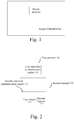
Fig. 1 is a schematic diagram of an interaction manner of near-field communication between a large screen terminal and a small screen mobile terminal in related art; -
Fig. 2 is a schematic structural diagram of a near-field communication system according to an embodiment of the present invention; -
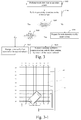
Fig. 3 is a flowchart of a detection method for performing channel switching at a fixed segmented location of a second terminal according to an embodiment of the present invention; -
Fig. 3-1 is a schematic diagram of channel switching at a fixed segmented location of a second terminal according to an embodiment of the present invention; -
Fig. 3-2 is a flowchart of a detection method of automatically detecting a segmented location and performing channel switching on a second terminal according to an embodiment of the present invention; -
Fig. 3-3 and Fig. 3-4 are schematic diagrams of automatically detecting a segmented location and performing channel switching on a display screen (some channels are omitted) of a second terminal according to an embodiment of the present invention; -
Fig. 4 is a schematic structural diagram of a near-field communication system according to another embodiment of the present invention; -
Fig. 5 is a flowchart of a detection method of dividing a display screen of a second terminal into two blocks according to an embodiment of the present invention; -
Fig. 5-1 is a schematic diagram of dividing a display screen of a second terminal into two blocks according to an embodiment of the present invention; -
Fig. 5-2 is a schematic diagram of dividing a display screen (some channels are omitted) of a second terminal into two blocks according to an embodiment of the present invention; -
Fig. 6 is a schematic structural diagram of a near-field communication system according to still another embodiment of the present invention; -
Fig. 7 is a schematic diagram of displaying a near-field communication identifier by a second terminal according to an embodiment of the present invention; -
Fig. 8 is a schematic structural diagram of a terminal according to an embodiment of the present invention; and -
Fig. 9 is a schematic structural diagram of a terminal according to another embodiment of the present invention. - The following describes embodiments of the present invention in detail and examples of the embodiments are shown in the accompanying drawings, where the same or similar reference numerals always represent the same or similar elements or elements having the same or similar functions. The following embodiments described with reference to the accompanying drawings are illustrative, only for the purpose to explain the present invention, and cannot be understood as limitations to the present invention. On the contrary, the embodiments of the present invention include all of changes, amendments, and equivalents that fall within a scope of spirit and connotations of the appended claims.
- In the description of the present invention, it should be understood that the terms "first," "second," and the like are only used for the purpose of description, and cannot be understood as an indication or implication of relative importance. In the description of the present invention, it should be noted that unless otherwise clearly stipulated and defined, the terms "connected" and "connection" should be understood in a broad sense. For example, the connection may be a fixed connection, a detachable connection, or an integral connection; the connection may be a mechanical connection, or an electrical connection; and the connection may be a direct connection or an indirect connection via a medium. For persons of ordinary skill in the art, specific meanings of the foregoing terms in the present invention can be understood in specific cases. In addition, in the description of the present invention, unless otherwise described, the meaning of "multiple" is two or more.
- Description of any process or method described in other manners in flowcharts or herein can be understood as: indicating one or more modules, segments, or parts configured to implement a specific logic function or a code of an executable instruction for steps of a process. In addition, a range of preferable implementation manners of the present invention include other implementations, where functions can be implemented without conforming to a shown or discussed sequence, including conforming to a basically synchronous manner or an inverse sequence according to involved functions, which should be understood by persons of ordinary skill in the technical field to which the embodiments of the present invention belong.
- The following describes, with reference to the accompanying drawings, a system and a terminal for cross-terminal communication according to embodiments of the present invention.
- Currently, during near-field communication between terminals, in most cases, a size of a first capacitive touch screen of a second terminal and a size of a second capacitive touch screen of a first terminal are significantly different. Therefore, quality of communication may be reduced, leading to a failure of data transmission. For example, as shown in
Fig. 1 , when a notebook computer performs near-field communication with a mobile phone, the screen of the notebook computer is in a power on state and waits for approaching of the mobile phone, and data transmission can be implemented when the mobile phone is in proximity to any location of the screen of the notebook computer. Although the foregoing manner has a lower requirement on user operation, a major problem may exist in application. Because an area for receiving effective data transmission signals in the notebook computer is smaller (the area for receiving effective data signals is no more than the area of the mobile phone), other receiving regions of the notebook computer cannot effectively receive data transmission signals and will receive noise. In addition, a non-effective part (for example, a part of a region that does not correspond to a mobile phone transmitting region) of the receiving regions in the notebook computer may further be coupled to a system ground GND of the mobile phone, which would cause effective signals to be canceled. When the mobile phone is in proximity to the notebook computer and transmits data transmission signals, the signals received by the notebook computer are relatively weak, and communication quality is relatively low, and it is difficult to implement stable transmission. Therefore, if the data transmission signals can be enhanced by reducing a receiving area of the notebook computer, that is, the mobile phone performs communication with the notebook computer in a specified communication region in the notebook computer, signal attenuation and external interference can be reduced, and communication quality can be improved. Hence, the present invention provides a system for cross-terminal communication. -
Fig. 2 is a schematic structural diagram of a near-field communication system according to an embodiment of the present invention. As shown inFig. 2 , the near-field communication system includes afirst terminal 100 and asecond terminal 200, where thefirst terminal 100 includes a first near-field communication region 110, and thesecond terminal 200 includes: a second near-field communication region 210, afirst subunit 211, and asecond subunit 212. - Specifically, the
first terminal 100 has the first near-field communication region 110, where thefirst terminal 100 may be a mobile phone or the like. Thesecond terminal 200 has the second near-field communication region 210, where thesecond terminal 200 may be a notebook computer, a palmtop computer, a television, a display, or the like. The second near-field communication region 210 includes thefirst subunit 211 and thesecond subunit 212. Thefirst subunit 211 and the second subunit 212or merely thesecond subunit 212 are (is) used to detect whether a distance between the first near-field communication region 110 and the second near-field communication region 210 is less than or equal to a preset distance. Thesecond subunit 212 is used to establish communication with the first near-field communication region 110 when the distance between the first near-field communication region 110 and the second near-field communication region 210 is less than or equal to a preset distance, where the first near-field communication region 110 may perform communication with thesecond subunit 212 of the second near-field communication region 210 by means of near-field communication. The foregoing detecting whether a distance between the first near-field communication region 110 and the second near-field communication region 210 is less than or equal to a preset distance can be implemented by prior art, which, to avoid redundancy, is not further described in detail herein. - For example, the first terminal 100 (for example, a mobile phone) has a near-field communication region of a smaller area, and the second terminal 200 (for example, a notebook computer or a tablet computer) has a near-field communication region of a larger area. For example, the
first terminal 100 is a mobile phone, and thesecond terminal 200 is a tablet computer; or thefirst terminal 100 is a palmtop computer, and thesecond terminal 200 is a notebook computer, or the like. Thefirst terminal 100 and thesecond terminal 200 have the first near-field communication region 110 and the second near-field communication region 210, respectively. For example, the first near-field communication region 110 is a display screen of a mobile phone, and the second near-field communication region 210 is a display screen of a notebook computer, or the first near-field communication region 110 is a display screen of a mobile phone, and the second near-field communication region 210 is a touchpad, or the like. - A communication process between the
first terminal 100 and thesecond terminal 200 may be divided into proximity detection and data communication. The proximity detection is a preparation phase of the data communication. Generally, touch detection and the proximity detection are performed in a time-sharing manner, and a data communication phase begins only after the proximity detection succeeds. The touch detection and the proximity detection may be referred to as a first detection phase, and data near-field communication may be referred to as a second detection phase. In the first detection phase, a touch device can support a touch function and a proximity detection function synchronously. The following mainly discusses the touch detection in the first detection phase, and a processing manner of the proximity detection is similar to that of the touch detection. - An objective of the proximity detection is to enable the
second terminal 200 to sense whether thefirst terminal 100 in communication with thesecond terminal 200 exists. Because in this proximity detection process, thesecond terminal 200 does not need to perform data transmission with thefirst terminal 100, a requirement on communication quality is lower. - Specifically, touch detection and proximity detection on different regions in the second near-
field communication region 210 of thesecond terminal 200 can be implemented by using a detection channel switching manner. -
Fig. 3 is a processing flowchart of performing fixed channel switching by a near-field communication system according to an embodiment of the present invention, and a specific process includes: - S102, first, performing a touch detection on an entire screen constituted by a
first subunit 211 and asecond subunit 212, so as to complete the touch detection of the first detection phase; - S104,performing a proximity detection on the entire screen constituted by the
first subunit 211 and thesecond subunit 212, so as to complete the proximity detection of the first detection phase; - S106, in a proximity detection phase, determining, according to a detection result, whether a distance between a first terminal 100anda
second terminal 200 less than or equal to a preset distance, if yes, proceeding to S108, and otherwise, proceeding to S110; - S108, determining, according to a proximity detection result of the
second subunit 212, whether thefirst terminal 100 is located therein, if yes, proceeding to S114, and otherwise, proceeding to S112; - S112, prompting a user to move the
first terminal 100 to thesecond subunit 212 of thesecond terminal 200, and proceeding to S102; and S114, if thefirst terminal 100 in the preset distance exists, performing data transmission by means of the second subunit to complete communication; - S110, if the
first terminal 100 in the preset distance does not exist, proceeding to S102 to perform the touch detection and the proximity detection again. - As shown in
Fig. 3-1 , a second near-field communication region 210 of thesecond terminal 200 may include thefirst subunit 211 and thesecond subunit 212. Specifically, the second near-field communication region 210 may be divided into two regions of different sizes, namely, the first subunit 211 (a region outside a dashed line box) and the second subunit 212 (a region inside the dashed line box), by means of software segmentation. When it is detected that a first near-field communication region 110 of thefirst terminal 100 is in proximity to the second near-field communication region 210 of thesecond terminal 200, communication with the first near-field communication region 110 of thefirst terminal 100 is established by thesecond subunit 212. When thesecond subunit 212 performs communication with the first near-field communication region 110, the first subunit 211 (some or all channels therein) in the second near-field communication region 210 is controlled to stop working. - Specifically, stopping working mainly refers to that channels keep a state of having smaller interference on other channels, for example, a disconnected (suspended) state or a direct-current fixed-level state, and in particular, refers to keeping the direct-current fixed-level state.
- As shown in
Fig. 3-1 , Y0 to Y7 are longitudinal channels, and X0 to X9 are transversal channels, and these electrodes are used as touch and near-field communication electrode channels (in a typical mutual capacitive touch screen, Y8 to Y10are drive channels, and X10 to X12 are sensing channels; and it should be understood that one detection channel may have both a driving function and a sensing function at the same time, and a detection channel mainly refers to an electrode channel having a sensing function). For the second near-field communication region 210 in which Y0 to Y7 are drive channels, and X0 to X9 are sensing channels, when touch scanning of the first detection phase is performed on the second near-field communication region 210, all electrode channels in the second near-field communication region 210 may be scanned. That is, not only all the drive channels and sensing channels in thefirst subunit 211, but also all the drive channels and sensing channels in thesecond subunit 212 are scanned. - In this case, the obtained data is used for touch processing on the second near-
field communication region 210. It should be understood that if proximity detection needs to be performed on the entire screen, the proximity detection of the first detection phase may be completed according to a processing manner similar to that of the foregoing touch detection. If proximity detection only needs to be performed on the second subunit, scanning is merely performed on all drive channels and sensing channels (for example, channels X7 to X9 in the region inside the dashed line region inFig. 3 ) of the specifiedsecond subunit 212, so as to complete the proximity detection processing. - When data near-field communication of the second detection phase is performed on the second near-
field communication region 210, scanning is merely performed on all detection channels (for example, the channels X7 to X9 in a dashed line region inFig. 3 ) of the specifiedsecond subunit 212, and in this case, the obtained data is used for communication processing on the second near-field communication region 210. Therefore, if near-field communication is performed with thefirst terminal 100 only by means of a specified region (that is, the second subunit 212), an area used for receiving effective signals of thesecond terminal 200 keeps unchanged, and an area used for overall receiving of thesecond terminal 200 is reduced. Hence, communication quality of signals is improved. - It should be understood that if X7 to X9 in the
second terminal 200 have both a driving function and a sensing function at the same time, during data transmission, driving and receiving may also be performed by merely using the channels X7 to X9 of thesecond subunit 212. Hence, power of thesecond terminal 200 can be saved. - The
second terminal 200 not only can support fixed segmented regions implemented via software, that is, setting in advance a plurality of detection channels of a specified region (for example, X7 to X9 inFig. 3 )in the second terminal as the second subunit, and setting the remaining detection channels as the first subunit, but also can dynamically set the detection channels on the second terminal overlapped with the first near-field communication region as the second subunit, and set the remaining detection channels as the first subunit. -
Fig. 3-2 is a flowchart of a processing method of automatically detecting a segmented location and performing channel switching on a display screen of a second terminal according to an embodiment of the present invention, where the method includes: - S202,first, performing touch detection on an entire screen constituted by a
first subunit 211 and asecond subunit 212 to complete the touch detection of the first detection phase; - S204, performing a proximity detection scanning separately on all channels in a second near-
field communication region 210, so as to complete the proximity detection of the first detection phase; - S206, in the proximity detection phase, determining, by means of a detection result, whether a distance between a
first terminal 100 and asecond terminal 200 is less than or equal to a preset distance, if yes, proceeding to S208, and otherwise, proceeding to S210; - S208, determining, according to a scanning result of each channel, a proximity location of the
first terminal 100; - S212, according to the proximity location of the first terminal, dividing detection channels in a region where the first terminal is overlapped with the second terminal as the
second subunit 212 for performing subsequent near-field communication and other channels outside the region as thefirst subunit 211; - S214, according to the regions divided in S212, the
second terminal 200 completing communication with the first terminal by means of thesecond subunit 212. - As shown in
Fig. 3-3 (Y channels are omitted in the figure), when the proximity detection of the first detection phase is performed on the second near-field communication region 210, the location of thesecond terminal 100 may be identified according to a difference between different channels wherein: first, the proximity detection scanning is performed on all channels on the entire screen; and by means of a data difference between different channels, it can be found that thefirst terminal 100 is placed in proximity to X3 and X4. As shown inFig. 3-4 , after the location wheresecond terminal 100 is placed is identified, thesecond terminal 200 automatically divides detection channels X3 and X4 of thesecond communication region 210 as thesecond subunit 212 for performing subsequent near-field communication. In this case, other channels constitute thefirst subunit 211. In a communication phase, merely some channels of thesecond subunit 212 specified in the figure are scanned and received, thereby improving communication quality. - The near-field communication system of the embodiment of the present invention, by means of software segmentation, uses a specified region in the near-field communication region of the second terminal as a dedicated communication region by using channel switching, and when detecting proximity of the first terminal, the second terminal performs near-field communication with the first terminal by means of the specified region, thereby reducing signal attenuation and external interference in data transmission and improving communication quality.
- Although in the foregoing embodiments, a problem that signals are weaker during data transmission between the
first terminal 100 and thesecond terminal 200 can be better solved by means of channel switching, in a case in which thesecond terminal 200 has a larger near-field communication region (for example, 20 inches or greater than 20 inches), because the spacing between driving channels or sensing channels in the second near-field communication region 210 of thesecond terminal 200 is excessively large, the problem that signals are weaker still exists in data transmission between thefirst terminal 100 and thesecond terminal 200. Therefore, in the following embodiments, the second near-field communication region 210 in thesecond terminal 200 may be further divided into two blocks by means of hardware segmentation, and a large second near-field communication region 210 is constituted by two electrode regions having independent driving channels and sensing channels. In this way, the problem that signals are weaker during data transmission between thefirst terminal 100 and thesecond terminal 200 can be resolved preferably. -
Fig. 4 is a schematic structural diagram of a near-field communication system according to another embodiment of the present invention. As shown inFig. 4 , the near-field communication system includes afirst terminal 100 and asecond terminal 200, where thefirst terminal 100 includes a first near-field communication region 110, and thesecond terminal 200 includes: a second near-field communication region 210 including afirst subunit 211 and asecond subunit 212. - Specifically, the second near-
field communication region 210 includes thefirst subunit 211 and thesecond subunit 212; thefirst subunit 211 and the second subunit 212or merely thesecond subunit 212 are (is)configured to detect whether a distance between the first near-field communication region 110 and the second near-field communication region 210 is less than or equal to a preset distance; thesecond subunit 212 is configured to establish communication with the first near-field communication region 110 when it is detected that the distance between the first near-field communication region 110 and the second near-field communication region 210 is less than or equal to a preset distance. - Further, when the
second terminal 200 does not detect that the distance between the first near-field communication region 110 and the second near-field communication region 210 is less than or equal to the preset distance, touch detection and proximity detection need to be performed on the second near-field communication region 210 of the second terminal in a time-sharing manner, and a data communication phase begins only after the proximity detection succeeds. Touch detection and proximity detection may be referred to as a first detection phase, and data near-field communication may be referred to as a second detection phase. -
Fig. 5 is a flowchart of a processing method of dividing a display screen of a second terminal into two blocks according to an embodiment of the present invention, and a specific process includes: - S302,separately scanning the
first subunit 211 and thesecond subunit 212, performing processing such as splicing to data, and after obtaining data of an entire screen, completing touch detection; - S304,separately scanning the
first subunit 211 and thesecond subunit 212, performing processing such as splicing to data, and after obtaining data of the entire screen, completing proximity detection; - S306, according to a proximity detection result, determining whether proximity of a
first terminal 100 is detected, if yes, proceeding to S308, and otherwise, proceeding to S310; - S310, if proximity of the
first terminal 100 does not exist, then proceeding to S302 to perform next touch detection, proximity detection, and the like again; - S308,determining, according to the proximity detection result of the
second subunit 212, whether thefirst terminal 100 is located therein, if yes, proceeding to S314, and otherwise, proceeding to S312; - S312, after it is determined that a distance between the
first terminal 100 and thesecond terminal 200 is less than or equal to a preset distance, prompting, by means of a certain means (for example, an identifier, etc.), a user to move thefirst terminal 100 to thesecond subunit 212, and then proceeding to S302; and - S314, the
second terminal 200 performing communication with thefirst terminal 100 by means of thesecond subunit 212. - As shown in
Fig. 5-1 , in this embodiment of the present invention, the second near-field communication region 210 of thesecond terminal 200 may be divided into two blocks, namely, afirst subunit 211 in a non-communication region and asecond subunit 212 in a communication region. Different fromFig. 2 , thesecond subunit 212 inFig. 5-1 has independent electrode channels (typically, for example, Y8 to Y10 are drive channels, and X10 to X12 are sensing channels; and it should be understood that each channel may also have both a driving function and a sensing function at the same time). That is, electrode channels in thefirst subunit 211 do not cover thesecond subunit 212, and the second near-field communication region 210 of thesecond terminal 200 is equivalent to being constituted by two electrode regions combined with each other. In this way, an area of a region for performing communication between the second near-field communication region 210 and the first near-field communication region 110 can be further reduced, thereby improving communication quality. - As shown in
Fig. 5-1 , during the touch detection, driving channels and sensing channels in thefirst subunit 211 and thesecond subunit 212 are controlled synchronously to separately obtain data of the two electrode regions. Then, splicing processing is performed on the data of the two electrode regions to obtain data of the second near-field communication region 210 for performing touch processing on the second near-field communication region 210. During the data near-field communication, only the driving channels and the sensing channels in thesecond subunit 212 are controlled to obtain data of thesecond subunit 212 for performing communication processing on the second near-field communication region 210. Specifically, during touch scanning of the first detection phase, all channels in thefirst subunit 211 and thesecond subunit 212 are scanned synchronously, and the data of the two electrode regions are combined to generate data of the entire second near-field communication region 210. For example, two parts of data, as shown in Table 1 and Table 2, can be obtained during the first detection phase, wherein:
A0 to A10, B0 to B10, A'0 to A'2...represent sampled data of each detection node, respectively. Typically, for example, A0 to A7 represent sampled data of nodes formed by X0 and Y0 to Y7, and A'0 to A'2 represent sampled data of nodes formed by X10 and Y8 to Y10, and so on.

Table 2 shows sampled data of the second subunit 212A'0 B'0 C'0 A'1 B'1 C'1 A'2 B'2 C'2 - Then, the data shown in Table 1 and Table 2 are combined to calculate the data, as shown in table 3, of the entire second near-
field communication region 210. In this way, a data collection process of the touch detection that is performed on the second near-field communication region 210 can be completed. - It should be understood that if the proximity detection needs to be performed on the entire screen, the data collection process of the proximity detection of the first detection phase may be completed according to a processing manner similar to that of the foregoing touch detection; and if the proximity detection only needs to be performed on the second subunit, merely the electrode channels of the specified
second subunit 212 are scanned, so as to complete data collection processing of the proximity detection.
- When communication scanning of the second detection phase is performed, merely electrode channels of a specified region are scanned, that is, in
Fig. 5 , merely a region constituted by Y8 to Y10 and X10 to X12 is scanned. In this case, the obtained data are used for communication processing on the second near-field communication region 210. -
Fig. 5-2 is a schematic structural diagram of relevant wiring in thesecond subunit 212 emphasized in such a way the relevant channels of thefirst subunit 211 inFig. 5 are omitted. - As shown in
Fig. 3-1 , when hardware segmentation is not performed, in the second near-field communication region 210, a peripheral wire is separately led out from one end of Y/X channels. As shown inFig. 5-1 and Fig. 5-2 , a segment is respectively cut out at an end of Y and an end of X by means of hardware segmentation, so as to constitute thesecond subunit 212. Thesecond subunit 212 performs wiring from one end of a screen body, for example, Y8 to Y10 and X10 to X12 in the figures; thefirst subunit 211 performs wiring from the other end of the screen body, for example, Y0 to Y7 and X0 to X9 in the figure. In the phase of the first detection phase, during the touch detection, all channels (including thefirst subunit 211 and the second subunit 212) participate in the detection; during the proximity detection, all channels (including thefirst subunit 211 and the second subunit 212) or channels in thesecond subunit 212 participate in the detection. However, in the second phase, only Y and X channels in thesecond subunit 212 participate in the near-field communication, thereby achieving an effect of reducing an overall signal receiving area. - In the communication phase, merely channels of the
second subunit 212 specified in the drawing are scanned and received, thereby improving communication quality. - The near-field communication system of the embodiment of the present invention, by means of hardware segmentation, uses the specified region in the near-field communication region of the second terminal as a dedicated communication region and makes it have independent electrode channels; and when detecting proximity of the first terminal, the second terminal performs data transmission with the first terminal by means of the specified region. In this way, signal attenuation and external interference in data transmission can be further reduced, thereby improving communication quality.
-
Fig. 6 is a schematic structural diagram of a near-field communication system according to another embodiment of the present invention. As shown inFig. 6 , the near-field communication system includes afirst terminal 100 and asecond terminal 200, where thefirst terminal 100 includes a first near-field communication region 110, and thesecond terminal 200 includes: a second near-field communication region 210 including afirst subunit 211 and asecond subunit 212. - Specifically, the
first terminal 100 has the first near-field communication region 110, where thefirst terminal 100 may be a mobile phone. - The
second terminal 200 has the second near-field communication region 210, where thesecond terminal 200 may be a notebook computer, a palmtop computer, a television, a display, or the like. The second near-field communication region 210 includes thefirst subunit 211 and thesecond subunit 212; thefirst subunit 211 and the second subunit 212or merely thesecond subunit 212 are (is) used to detect whether a distance between the first near-field communication region 110 and the second near-field communication region 210 is less than or equal to a preset distance; and thesecond subunit 212 is used to establish communication with the first near-field communication region 110 when the distance between the first near-field communication region 110 and the second near-field communication region 210 is less than or equal to a preset distance, where the first near-field communication region 110 performs communication with thesecond subunit 212 of the second near-field communication region 210 by means of near-field communication. - In this embodiment of the present invention, if an entire screen can be used to perform proximity detection, the
second subunit 212 of the second near-field communication region 210 has a prompt identifier. When determining that the distance between the first near-field communication region 110 and the second near-field communication region 210 is less than or equal to the preset distance, thesecond terminal 200 sends a prompt of placing the first near-field communication region 110 to thesecond subunit 212. Specifically, as shown inFig. 7 , when thesecond terminal 200 is in proximity to thefirst terminal 100, a user may be prompted, by means of a user interface (UI), to place thefirst terminal 100 on thesecond subunit 212. For example, a near-field communication identifier may pop out on the second subunit 212 (for example, a middle location or a lower right corner) of thesecond terminal 200, and display to a user for prompting. In addition to popping out a near-field communication identifier to prompt a user, when the near-field communication identifier pops out, thesecond subunit 212 may also be controlled to flash to further prompt the user. - In the near-field communication system of this embodiment of the present invention, displaying the prompt identifier in the second subunit of the second near-field communication region enables a user to make the first terminal contact with/approach to the second terminal at any location. Meanwhile, the second subunit prompts the user to perform communication at a fixed location. In this way, a friendly interaction manner can be provided, thereby improving user experience.
- To implement the foregoing embodiment, the present invention further provides a terminal.
-
Fig. 8 is a schematic structural diagram of a terminal according to an embodiment of the present invention. As shown inFig. 8 , a terminal 200 includes a near-field communication region 210, where the near-field communication region 210 includes afirst subunit 211 and asecond subunit 212. - Specifically, the terminal 200 includes the near-
field communication region 210, where the terminal 200 may be a notebook computer, a palmtop computer, a television, a display, or the like, and other terminal(s) may be a mobile phone, and the like. The near-field communication region 210 includes thefirst subunit 211 and thesecond subunit 212; thefirst subunit 211 and the second subunit 212or merely the second subunit are (is) used to detect whether a distance between the near-field communication region 21 and a near-field communication region of other terminal(s) is less than or equal to a preset distance; thesecond subunit 212 is configured to establish communication with the near-field communication region of other terminal(s) when thefirst subunit 211 detects that the distance between the near-field communication region 210 and the near-field communication region of other terminal(s) is less than or equal to the preset distance. Thesecond subunit 212 performs communication with the near-field communication region of other terminal(s) by means of near-field communication. The foregoing detecting whether a distance between the near-field communication region 210 and the near-field communication region of other terminal(s) is less than or equal to a preset distance maybe implemented by prior art, which, to avoid redundancy, is not further described in detail herein. - Specifically, the terminal 200 has the near-
field communication region 210 of a larger area(for example, greater than 10 inches) with respect to other terminals. For example, the terminal 200 is a tablet computer, and other terminal(s) is a mobile phone; or the terminal 200 is a notebook computer, and other terminal(s) is a palmtop computer, or the like. For example, the near-field communication region 210 of the terminal 200 is a display screen of a notebook computer, and the near-field communication region of other terminal(s) is a display screen of a mobile phone; or the near-field communication region 210 of the terminal 200 is a touchpad, and the near-field communication region of other terminal(s) is a display screen of a mobile phone, or the like. - As shown in
Fig. 3-1 , the near-field communication region 210 of the terminal 200 may include thefirst subunit 211 and thesecond subunit 212. Specifically, the near-field communication region 210 may be divided into two regions of different sizes, namely, the first subunit 211 (a region outside a dashed line box) and the second subunit 212 (a region inside the dashed line box), by means of software segmentation. It should be understood that an area of thesecond subunit 212 is less than that of thefirst subunit 211. When it is detected that a near-field communication region of other terminal(s) is in proximity to the near-field communication region 210 of the terminal 200, communication with a communication body of the other terminal(s) is established by thesecond subunit 212. When thesecond subunit 212 performs communication with the near-field communication region of the other terminal(s), the first subunit 211 (some or all channels therein) in the near-field communication region 210 stop working. - Specifically, stopping working mainly refers to that channels keep a state of having smaller interference on other channels, for example, a disconnected (suspended) state or a direct-current fixed-level state, and in particular, refers to keeping the direct-current fixed-level state.
- Further, a communication process between other terminal(s) and the terminal 200 may be divided into two parts, that is, proximity detection and data communication. The proximity detection is a preparation phase of the data communication. Generally, touch detection and the proximity detection are performed in a time-sharing manner, anda data communication phase begins only after the proximity detection succeeds. Touch detection and proximity detection may be referred to as first detection phase, and near-field communication may be referred to as second detection phase. The following mainly discusses the touch detection, and a processing manner of the proximity detection is similar to that of the touch detection.
- An objective of the proximity detection is to enable the terminal 200 to sense whether other terminal(s)in communication with the terminal 200 exists. Because in this case, the terminal 200 does not need to perform data transmission with other terminal(s), a requirement on communication quality is lower.
- Specifically, touch detection and near-field communication of different regions in the near-
field communication region 210 of the terminal 200 can be implemented by means of channel switching. As shown inFig. 3-1 , Y0 to Y7 are longitudinal channels, and X0-X9 are transversal channels (typically, for example, Y8 to Y10 are drive channels, and X10-X12 are sensing channels; it should be understood that one channel may also have both a driving function and a sensing function at the same time; and a detection channel mainly refers to an electrode channel having a sensing function). For the near-field communication region 210 in which Y0-Y7 are drive channels, and X0-X9 are sensing channels, when touch scanning of the first detection phase is performed on the near-field communication region 210, scanning should be performed on all the drive channels and sensing channels in the near-field communication region 210. That is, not only all drive channels and sensing channels in thefirst subunit 211, but also all drive channels and sensing channels in thesecond subunit 212 are scanned. In this case, the obtained data are used for touch processing on the near-field communication region 210. It should be understood that if the proximity detection needs to be performed on an entire screen, the proximity detection of the first detection phase may be completed according to a processing manner similar to that of the foregoing touch detection; if the proximity detection only needs to be performed on the second subunit, merely all drive channels and some sensing channels (for example, channels X7 to X9 in the region inside the dotted box inFig. 3 ) of the specifiedsecond subunit 212 are scanned, so as to complete proximity detection processing. - When communication scanning of the second phase is performed on the near-
field communication region 210, merely all drive channels and some sensing channels (the channels X7 to X9 in the region inside the dotted box inFig. 3 ) of the specifiedsecond subunit 212 are scanned. In this case, the obtained data is used for communication processing on the near-field communication region 210. Therefore, if communication is performed with other terminal(s) only by means of a specified region (that is, the second subunit 212), an area, used for receiving effective signals, of the terminal 200 keeps unchanged, and an area, used for overall receiving, of the terminal 200 is reduced, thereby improving communication quality of signals. - It should be understood that if X7 to X9 in the terminal 200 have both a driving function and a sensing function at the same time, during data transmission, driving and receiving can also be performed by merely using the channels X7 to X9 in the
second subunit 212. Therefore, power of the terminal can be saved. - The terminal of this embodiment of the present invention uses the specified region in the near-field communication region of the terminal as a dedicated communication region, and when detecting proximity of other terminal(s), the terminal performs data transmission with the other terminal(s) by means of the specified region. In this way, signal attenuation and external interference in data transmission can be reduced, thereby improving communication quality.
-
Fig. 9 is a schematic structural diagram of a terminal according to a specific embodiment of the present invention. As shown inFig. 9 , a terminal 200 includes a near-field communication region 210, where the near-field communication region 210 includes afirst subunit 211 and asecond subunit 212. - Specifically, the near-
field communication region 210 may further include thefirst subunit 211 and thesecond subunit 212; thefirst subunit 211 and the second subunit 212or merely thesecond subunit 212 are (is) used to detect whether a distance between the near-field communication region 210 of the terminal 200 and the near-field communication region of other terminal(s) is less than or equal to a preset distance. Thesecond subunit 212 is used to establish communication with the near-field communication region of other terminal(s) when it is detected that the distance between the near-field communication region 210 and the near-field communication region of other terminal(s) is less than or equal to the preset distance. - As shown in
Fig. 5-1 , in this embodiment of the present invention, the near-field communication region 210 of the terminal 200 may be divided into two blocks, namely, thefirst subunit 211 in a non-communication region and thesecond subunit 212 in a communication region. Thesecond subunit 212 has independent electrode channels (typically, for example, Y8 to Y10 are drive channels, and X10 to X12 are sensing channels; it should be understood that each channel may also have both a driving function and a sensing function at the same time; and a detection channel mainly refers to an electrode channel having a sensing function). That is, electrode channels in thefirst subunit 211 do not cover up thesecond subunit 212, and the near-field communication region 210 of the terminal 200 is equivalent to being constituted by two electrode regions combined with each other. In this way, an area of a region used for performing communication between the near-field communication region 210 of the terminal 200 and the near-field communication region of other terminal(s) can be further reduced, thereby improving communication quality. - Further, when the terminal 200 does not detect that the distance between the near-
field communication region 210 and the near-field communication region of other terminal(s) is less than or equal to the preset distance, touch detection and proximity detection need to be performed on the near-field communication region of other terminal(s) in a time-sharing manner. Touch detection + proximity detection may be referred to as first detection phase, and near-field communication may be referred to as second-phase detection. - During the touch detection, drive channels and sensing channels in the
first subunit 211 and thesecond subunit 212 are controlled synchronously to separately obtain data of the two electrode regions. Then splicing processing is performed on the data of the two electrode regions to obtain data of the near-field communication region 210 for performing touch processing on the near-field communication region 210. During the near-field communication, only the drive channels and the sensing channels in thesecond subunit 212 need to be controlled to obtain data of thesecond subunit 212 for performing communication processing on the near-field communication region 210. Specifically, during touch scanning of the first detection phase, all channels in thefirst subunit 211 and thesecond subunit 212 are scanned synchronously, and the data of the two electrode regions are combined to generate data of the entire near-field communication region 210. For example, two parts of data, as shown in Table 1 and Table 2, can be obtained during the first detection phase, wherein:
A0 to A10, B0 to B10, A'0 to A'2...separately represent sampled data of each detection node, respectively. Typically, for example, A0 to A7 represent sampled data of nodes formed by X0 and Y0 to Y7, and A'0 to A'2 represent sampled data of nodes formed by X10 and Y8 to Y10, and so on.
Table 2 shows sampled data of the second subunit 212A'0 B'0 C'0 A'1 B'1 C'1 A'2 B'2 C'2 - Then, the data shown in Table 1 and Table 2 are combined to calculate the data, as shown in Table 3, of the entire near-
field communication region 210. In this way, a data collection process of the touch detection that is performed on the near-field communication region 210 can be completed. - It should be understood that if the proximity detection needs to be performed on an entire screen, the data collection process of the proximity detection of the first detection phase may be completed according to a processing manner similar to that of the foregoing touch detection; if the proximity detection only needs to be performed on the second subunit, merely the electrode channels of the specified
second subunit 212 are scanned, so as to complete data collection processing of the proximity detection.
- When communication scanning of the second detection phase is performed, merely electrode channels of a specified region are scanned, that is, as shown in
Fig. 5-1 , merely a region constituted by Y8 to Y10 and X10 to X12 is scanned. In this case, the obtained data is used for communication processing on the second near-field communication region 210. In this way, by means of hardware segmentation, the specified region in the near-field communication region 210 of the terminal 200 is used as a dedicated communication region and is enabled to have independent electrode channels. When detecting proximity of other terminal(s), the terminal 200 performs data transmission with the other terminal(s) by means of the specified region. In this way, signal attenuation and external interference in data transmission can be further reduced, thereby improving communication quality. - In this embodiment of the present invention, proximity detection can be performed on the entire screen, and the
second subunit 212 of the near-field communication region 210 has a prompt identifier. When determining that the distance between the near-field communication region 210 and the near-field communication region of other terminal(s) is less than or equal to the preset distance, the terminal 200 sends a prompt of placing the near-field communication region of other terminal(s)to thesecond subunit 212. Specifically, as shown inFig. 7 , when other terminal(s) is in proximity to the terminal 200, the terminal 200 may prompt a user, by means of a UI, to place other terminal(s) on thesecond subunit 212. For example, a near-field communication identifier may pop out in or near the second subunit 212 (for example, a middle location or a lower right corner) of the terminal 200, and display to a user for prompting. In addition to popping out a near-field communication identifier to prompt a user, when the near-field communication identifier pops out, thesecond subunit 212 may also be controlled to flash to further prompt the user. Therefore, displaying the prompt identifier in thesecond subunit 212 of the near-field communication region 210 enables a user to make other terminal(s) contact with the terminal 200 at any location. Meanwhile, thesecond subunit 212 prompts the user to perform communication at a fixed location. In this way, a friendly interaction manner can be provided, thereby improving user experience. - The terminal of this embodiment of the present invention uses the specified region in the near-field communication region of the terminal as a dedicated communication region and makes it have independent electrode channels. When detecting proximity of other terminal(s), the terminal performs data transmission with the other terminal(s) by means of the specified region. In this way, signal attenuation and external interference in data transmission can be reduced, thereby improving communication quality.
- In should be understood that each part of the present invention may be implemented by using hardware, software, firmware, or a combination thereof. In the foregoing implementation manners, multiple steps or methods may be implemented by using software or firmware that is stored in a memory and executed by an appropriate instruction execution system. For example, if the multiple steps or methods are implemented by using hardware, the same as that in another implementation manner, any one of the following technologies that are well known in the art or a combination thereof may be used to implement: a discrete logic circuit having a logic gate circuit used to implement a logic function on a data signal, a dedicated integrated circuit having an appropriate combinatorial logic gate circuit, a programmable gate array (PGA), a field programmable gate array (FPGA), and the like.
- In the description of the present specification, description of reference terms such as "an embodiment", "some embodiments", "examples", "specific examples", or "some examples", etc., means that specific features, structures, materials or characteristics described with reference to the embodiment or example are included in at least one embodiment or example of the present invention. In the present specification, exemplary expression on the foregoing terms does not necessarily refer to the same embodiment or example. In addition, the described specific features, structures, materials or characteristics may be combined in an appropriate manner in any one or more embodiments or examples.
- Although the embodiments of the present invention are shown and described, persons of ordinary skill in the art can understand: various changes, modifications, substitutions, and variations can be made to these embodiments without departing from the principle and objectives of the present invention; the scope of the present invention is defined by claims and equivalents thereof.
- The near-field communication system of the embodiments of the present invention uses a specified region in a near-field communication region of a second terminal as a dedicated communication region. When detecting proximity of a first terminal, the second terminal performs data transmission with the first terminal by means of the specified region. In this way, signal attenuation and external interference in data transmission can be reduced, thereby improving communication quality.
- The terminal of the embodiments of the present invention uses a specified region in a near-field communication region of the terminal as a dedicated communication region. When detecting proximity of other terminal(s), the terminal performs data transmission with the other terminal(s) by means of the specified region. In this way, signal attenuation and external interference in data transmission can be reduced, thereby improving communication quality.
Claims (14)
- A near-field communication system, comprising:a first terminal, wherein the first terminal has a first near-field communication region; anda second terminal, wherein the second terminal has a second near-field communication region, and the second near-field communication region has a first subunit and a second subunit, wherein the first subunit and the second subunit are configured to detect a distance between the first near-field communication region and the second near-field communication region, and the second subunit is configured to establish communication with the first near-field communication region when the distance between the first near-field communication region and the second near-field communication region is less than or equal to a preset distance; orthe second subunit is configured to detect a distance between the first near-field communication region and the second near-field communication region, and the second subunit is configured to establish communication with the first near-field communication region when the distance between the first near-field communication region and the second near-field communication region is less than or equal to a preset distance.
- The near-field communication system according to claim 1, wherein the second terminal is a capacitive touch screen terminal, and the detection channels of a capacitive touch screen are divided into the first subunit and the second subunit by means of hardware segmentation.
- The near-field communication system according to claim 1, wherein the second terminal is a capacitive touch screen terminal, and detection channels of a capacitive touch screen are divided into the first subunit and the second subunit by means of software segmentation; and detection channels of a predetermined region of the second terminal are set as the second subunit and the remaining detection channels are set as the first subunit; or detection channels on the second terminal overlapped with the first near-field communication region are set as the second subunit, and the remaining detection channels are set as the first subunit.
- The near-field communication system according to claim 2 or 3, wherein an area of the detection channels of the second subunit is less than that of the detection channels of the first subunit.
- The near-field communication system according to claim 2 or 3, wherein when the second subunit of the second near-field communication region performs communication with the first near-field communication region, the first subunit of the second near-field communication region is controlled to stop working.
- The near-field communication system according to claim 2 or 3, wherein the second subunit of the second near-field communication region has a prompt identifier.
- The near-field communication system according to claim 1, wherein an area of the near-field communication region of the first terminal is less than that of the second terminal, and the second terminal is further configured to send a prompt of placing the first near-field communication region to the second subunit when determining that the distance between the first near-field communication region and the second near-field communication region is less than or equal to the preset distance.
- A terminal, comprising:a near-field communication region, wherein the near-field communication region has a first subunit and a second subunit, and the first subunit and the second subunit are configured to detect a distance between the first near-field communication region and the second near-field communication region, and the second subunit is configured to establish communication with the first near-field communication region when the distance between the first near-field communication region and the second near-field communication region is less than or equal to a preset distance; or the second subunit is configured to detect a distance between the first near-field communication region and the second near-field communication region, and the second subunit is configured to establish communication with the first near-field communication region when the distance between the first near-field communication region and the second near-field communication region is less than or equal to a preset distance.
- The terminal according to claim 8, wherein the terminal is a capacitive touch screen terminal, and detection channels of a capacitive touch screen are divided into the first subunit and the second subunit by means of hardware segmentation.
- The terminal according to claim 8, wherein the second terminal is a capacitive touch screen terminal, and detection channels of a capacitive touch screen are divided into the first subunit and the second subunit by means of software segmentation; and detection channels of a specified region on the second terminal are set as the second subunit and the remaining detection channels are set as the first subunit; or detection channels on the second terminal overlapped with the first near-field communication region are set as the second subunit, and the remaining detection channels are set as the first subunit.
- The terminal according to claim 9 or 10, wherein an area of the detection channels of the second subunit is less than that of the detection channels of the first subunit.
- The terminal according to claim 9 or 10, wherein when the second subunit of the near-field communication region performs communication with the near-field communication region of the other terminal(s), the first subunit of the near-field communication region stops working.
- The terminal according to claim 9 or 10, wherein the second subunit of the near-field communication region has a prompt identifier.
- The terminal according to claim 8, wherein when an area of a near-field communication region of other terminal(s) is less than that of the terminal, the terminal is further configured to send a prompt of placing the near-field communication region of the other terminal(s) to the second subunit when determining that a distance between the near-field communication region and the near-field communication region of the other terminal(s) is less than or equal to the preset distance.
Applications Claiming Priority (2)
| Application Number | Priority Date | Filing Date | Title |
|---|---|---|---|
| CN201410108947.4A CN103944614B (en) | 2014-03-21 | 2014-03-21 | Near field communication system and terminals |
| PCT/CN2014/084148 WO2015139410A1 (en) | 2014-03-21 | 2014-08-12 | Near-field communication system and terminal |
Publications (3)
| Publication Number | Publication Date |
|---|---|
| EP3121970A1 true EP3121970A1 (en) | 2017-01-25 |
| EP3121970A4 EP3121970A4 (en) | 2017-12-06 |
| EP3121970B1 EP3121970B1 (en) | 2020-01-01 |
Family
ID=51192127
Family Applications (1)
| Application Number | Title | Priority Date | Filing Date |
|---|---|---|---|
| EP14886158.6A Active EP3121970B1 (en) | 2014-03-21 | 2014-08-12 | Near-field communication system and terminal |
Country Status (5)
| Country | Link |
|---|---|
| US (1) | US10201028B2 (en) |
| EP (1) | EP3121970B1 (en) |
| KR (1) | KR101972643B1 (en) |
| CN (1) | CN103944614B (en) |
| WO (1) | WO2015139410A1 (en) |
Families Citing this family (6)
| Publication number | Priority date | Publication date | Assignee | Title |
|---|---|---|---|---|
| CN103944614B (en) * | 2014-03-21 | 2017-01-11 | 深圳市汇顶科技股份有限公司 | Near field communication system and terminals |
| CN104485983B (en) * | 2014-12-09 | 2017-12-08 | 深圳市汇顶科技股份有限公司 | Touch-screen, terminal and its near field communication method of integrated NFC antenna |
| CN104954947A (en) * | 2015-06-12 | 2015-09-30 | 深圳市金立通信设备有限公司 | Sound box, audio playing system and audio playing method |
| CN107086355B (en) * | 2017-06-10 | 2024-03-15 | 新开普电子股份有限公司 | Electronic device with flat panel display and NFC antenna |
| KR102671154B1 (en) * | 2018-12-31 | 2024-05-30 | 엘지디스플레이 주식회사 | Display apparatus with integrated antenna |
| CN113158108B (en) * | 2021-04-27 | 2024-09-13 | 维沃移动通信有限公司 | Method and device for displaying information, and electronic device |
Family Cites Families (21)
| Publication number | Priority date | Publication date | Assignee | Title |
|---|---|---|---|---|
| US20100081375A1 (en) * | 2008-09-30 | 2010-04-01 | Apple Inc. | System and method for simplified control of electronic devices |
| US9559405B2 (en) * | 2009-06-12 | 2017-01-31 | Qualcomm Incorporated | Devices and methods related to a display assembly including an antenna |
| JP5725672B2 (en) * | 2010-06-10 | 2015-05-27 | エンパイア テクノロジー ディベロップメント エルエルシー | Communication between touch panel devices |
| EP2434793B1 (en) * | 2010-09-23 | 2014-03-12 | BlackBerry Limited | Mobile wireless communications device establishing wireless communication links based upon near field communication and related methods |
| CN102545973A (en) * | 2010-12-28 | 2012-07-04 | 中国银联股份有限公司 | Wireless communication system, display, payment transaction system and payment transaction method |
| US9030422B2 (en) * | 2011-02-15 | 2015-05-12 | Lg Electronics Inc. | Method of transmitting and receiving data and display device using the same |
| US20120268414A1 (en) * | 2011-04-25 | 2012-10-25 | Motorola Mobility, Inc. | Method and apparatus for exchanging data with a user computer device |
| CN202217780U (en) * | 2011-08-29 | 2012-05-09 | 东莞宇龙通信科技有限公司 | Antenna and mobile terminal for short-distance wireless communication |
| CN102508518A (en) * | 2011-11-02 | 2012-06-20 | 青岛金弘测控技术发展有限公司 | Tablet personal computer with multiple radio frequency modules |
| KR20130056081A (en) * | 2011-11-21 | 2013-05-29 | 삼성전기주식회사 | Device and method for sensing touch input |
| CN102819346B (en) * | 2012-04-06 | 2016-01-13 | 信利工业(汕尾)有限公司 | A kind of touch-screen of integrated NFC antenna |
| WO2013172829A1 (en) * | 2012-05-16 | 2013-11-21 | Blackberry Limited | Portable electronic device and method of controlling same |
| KR101969350B1 (en) * | 2012-08-20 | 2019-04-16 | 엘지전자 주식회사 | Mobile terminal and method for controlling the same |
| CN102916729B (en) * | 2012-09-04 | 2014-12-10 | 深圳市汇顶科技股份有限公司 | Near-field communication method and system of touch panel terminal as well as touch panel terminal |
| CN102882545B (en) * | 2012-09-21 | 2015-08-05 | 敦泰科技有限公司 | Communication equipment |
| CN104007903B (en) * | 2013-02-27 | 2017-03-22 | 联想(北京)有限公司 | Interface invoking method, interface invoking device, and electronic device |
| CN103259569B (en) * | 2013-05-14 | 2015-04-22 | 深圳市汇顶科技股份有限公司 | Touch terminals and near-field communication method and system thereof |
| CN103279303A (en) * | 2013-05-31 | 2013-09-04 | 东莞宇龙通信科技有限公司 | Event message processing method and device |
| CN103440075B (en) * | 2013-08-13 | 2017-03-29 | 深圳市汇顶科技股份有限公司 | A kind of capacitive touch screen terminal and its near field communication method, system |
| US20150138142A1 (en) * | 2013-11-15 | 2015-05-21 | Mediatek Inc. | Method for performing touch communications control of an electronic device by using location detection with aid of touch panel, and an associated apparatus |
| CN103944614B (en) * | 2014-03-21 | 2017-01-11 | 深圳市汇顶科技股份有限公司 | Near field communication system and terminals |
-
2014
- 2014-03-21 CN CN201410108947.4A patent/CN103944614B/en active Active
- 2014-08-12 EP EP14886158.6A patent/EP3121970B1/en active Active
- 2014-08-12 WO PCT/CN2014/084148 patent/WO2015139410A1/en not_active Ceased
- 2014-08-12 KR KR1020167029193A patent/KR101972643B1/en active Active
-
2016
- 2016-09-21 US US15/272,059 patent/US10201028B2/en active Active
Also Published As
| Publication number | Publication date |
|---|---|
| EP3121970B1 (en) | 2020-01-01 |
| US20170013660A1 (en) | 2017-01-12 |
| WO2015139410A1 (en) | 2015-09-24 |
| EP3121970A4 (en) | 2017-12-06 |
| CN103944614B (en) | 2017-01-11 |
| US10201028B2 (en) | 2019-02-05 |
| KR101972643B1 (en) | 2019-05-29 |
| CN103944614A (en) | 2014-07-23 |
| KR20160136380A (en) | 2016-11-29 |
Similar Documents
| Publication | Publication Date | Title |
|---|---|---|
| EP3121970B1 (en) | Near-field communication system and terminal | |
| US12197657B2 (en) | Active pen and sensor controller that use data generated from identification data | |
| CN107094294B (en) | Network connection method and device | |
| US20190129681A1 (en) | Wireless Screen Transmission Method, Extension Device, and Wireless Screen Transmission System | |
| US10269163B2 (en) | Method and apparatus for switching real-time image in instant messaging | |
| US10145735B2 (en) | Electromagnetic wave measuring device, electromagnetic wave measuring method, and programs therefor | |
| EP2897035A1 (en) | Dynamic threshold for local connectivity setup | |
| US12016064B2 (en) | Method for establishing hotspot connection and terminal device | |
| US11032862B2 (en) | Device and communication connection method for connecting multiple devices | |
| EP3101528B1 (en) | Method for controlling a display of an electronic device and the electronic device thereof | |
| WO2019024795A1 (en) | Antenna beam detection system, method, and mobile terminal | |
| EP3490305B1 (en) | Wireless fidelity (wi-fi) scanning method and related product | |
| CN106101776A (en) | Volume adjustment method, smart device and speaker | |
| WO2019062175A1 (en) | Information input method and device | |
| CN105338445A (en) | Signal transmission device, method and mobile terminal | |
| CN105700801A (en) | Interface interception method and device | |
| CN113115101A (en) | LED display screen, distributed information display system and control method | |
| CN105607841A (en) | Control method, control device and electronic device | |
| JP2020054443A (en) | Jaw evaluation system and jaw evaluation method | |
| CN104898900B (en) | A kind of method and infrared touch frame of the scanning of infrared touch frame | |
| CN107969027A (en) | wireless network management method, wireless network management device and intelligent terminal | |
| JP6444744B2 (en) | Information processing device | |
| CN105630364B (en) | A kind of information processing method and electronic equipment | |
| CN114967983A (en) | Touch recognition method, device, device and interactive smart tablet | |
| JP6034672B2 (en) | Drawing system |
Legal Events
| Date | Code | Title | Description |
|---|---|---|---|
| STAA | Information on the status of an ep patent application or granted ep patent |
Free format text: STATUS: THE INTERNATIONAL PUBLICATION HAS BEEN MADE |
|
| PUAI | Public reference made under article 153(3) epc to a published international application that has entered the european phase |
Free format text: ORIGINAL CODE: 0009012 |
|
| STAA | Information on the status of an ep patent application or granted ep patent |
Free format text: STATUS: REQUEST FOR EXAMINATION WAS MADE |
|
| 17P | Request for examination filed |
Effective date: 20161004 |
|
| AK | Designated contracting states |
Kind code of ref document: A1 Designated state(s): AL AT BE BG CH CY CZ DE DK EE ES FI FR GB GR HR HU IE IS IT LI LT LU LV MC MK MT NL NO PL PT RO RS SE SI SK SM TR |
|
| AX | Request for extension of the european patent |
Extension state: BA ME |
|
| DAX | Request for extension of the european patent (deleted) | ||
| RAP1 | Party data changed (applicant data changed or rights of an application transferred) |
Owner name: SHENZHEN GOODIX TECHNOLOGY CO., LTD. |
|
| A4 | Supplementary search report drawn up and despatched |
Effective date: 20171108 |
|
| RIC1 | Information provided on ipc code assigned before grant |
Ipc: G06F 3/044 20060101ALI20171102BHEP Ipc: G09G 5/00 20060101ALI20171102BHEP Ipc: H04B 5/00 20060101AFI20171102BHEP Ipc: H04W 76/02 20090101ALI20171102BHEP |
|
| STAA | Information on the status of an ep patent application or granted ep patent |
Free format text: STATUS: EXAMINATION IS IN PROGRESS |
|
| 17Q | First examination report despatched |
Effective date: 20181015 |
|
| REG | Reference to a national code |
Ref country code: DE Ref legal event code: R079 Ref document number: 602014059510 Country of ref document: DE Free format text: PREVIOUS MAIN CLASS: H04B0005000000 Ipc: H04W0076140000 |
|
| RIC1 | Information provided on ipc code assigned before grant |
Ipc: H04B 5/00 20060101ALI20190410BHEP Ipc: H04W 76/14 20180101AFI20190410BHEP Ipc: G09G 5/00 20060101ALI20190410BHEP Ipc: G06F 3/044 20060101ALI20190410BHEP |
|
| GRAP | Despatch of communication of intention to grant a patent |
Free format text: ORIGINAL CODE: EPIDOSNIGR1 |
|
| STAA | Information on the status of an ep patent application or granted ep patent |
Free format text: STATUS: GRANT OF PATENT IS INTENDED |
|
| INTG | Intention to grant announced |
Effective date: 20190613 |
|
| GRAS | Grant fee paid |
Free format text: ORIGINAL CODE: EPIDOSNIGR3 |
|
| GRAJ | Information related to disapproval of communication of intention to grant by the applicant or resumption of examination proceedings by the epo deleted |
Free format text: ORIGINAL CODE: EPIDOSDIGR1 |
|
| GRAL | Information related to payment of fee for publishing/printing deleted |
Free format text: ORIGINAL CODE: EPIDOSDIGR3 |
|
| STAA | Information on the status of an ep patent application or granted ep patent |
Free format text: STATUS: EXAMINATION IS IN PROGRESS |
|
| GRAR | Information related to intention to grant a patent recorded |
Free format text: ORIGINAL CODE: EPIDOSNIGR71 |
|
| STAA | Information on the status of an ep patent application or granted ep patent |
Free format text: STATUS: GRANT OF PATENT IS INTENDED |
|
| INTC | Intention to grant announced (deleted) | ||
| GRAA | (expected) grant |
Free format text: ORIGINAL CODE: 0009210 |
|
| STAA | Information on the status of an ep patent application or granted ep patent |
Free format text: STATUS: THE PATENT HAS BEEN GRANTED |
|
| AK | Designated contracting states |
Kind code of ref document: B1 Designated state(s): AL AT BE BG CH CY CZ DE DK EE ES FI FR GB GR HR HU IE IS IT LI LT LU LV MC MK MT NL NO PL PT RO RS SE SI SK SM TR |
|
| INTG | Intention to grant announced |
Effective date: 20191126 |
|
| REG | Reference to a national code |
Ref country code: GB Ref legal event code: FG4D |
|
| REG | Reference to a national code |
Ref country code: CH Ref legal event code: EP Ref country code: AT Ref legal event code: REF Ref document number: 1221474 Country of ref document: AT Kind code of ref document: T Effective date: 20200115 |
|
| REG | Reference to a national code |
Ref country code: IE Ref legal event code: FG4D |
|
| REG | Reference to a national code |
Ref country code: DE Ref legal event code: R096 Ref document number: 602014059510 Country of ref document: DE |
|
| REG | Reference to a national code |
Ref country code: NL Ref legal event code: MP Effective date: 20200101 |
|
| REG | Reference to a national code |
Ref country code: LT Ref legal event code: MG4D |
|
| PG25 | Lapsed in a contracting state [announced via postgrant information from national office to epo] |
Ref country code: CZ Free format text: LAPSE BECAUSE OF FAILURE TO SUBMIT A TRANSLATION OF THE DESCRIPTION OR TO PAY THE FEE WITHIN THE PRESCRIBED TIME-LIMIT Effective date: 20200101 Ref country code: RS Free format text: LAPSE BECAUSE OF FAILURE TO SUBMIT A TRANSLATION OF THE DESCRIPTION OR TO PAY THE FEE WITHIN THE PRESCRIBED TIME-LIMIT Effective date: 20200101 Ref country code: NO Free format text: LAPSE BECAUSE OF FAILURE TO SUBMIT A TRANSLATION OF THE DESCRIPTION OR TO PAY THE FEE WITHIN THE PRESCRIBED TIME-LIMIT Effective date: 20200401 Ref country code: FI Free format text: LAPSE BECAUSE OF FAILURE TO SUBMIT A TRANSLATION OF THE DESCRIPTION OR TO PAY THE FEE WITHIN THE PRESCRIBED TIME-LIMIT Effective date: 20200101 Ref country code: LT Free format text: LAPSE BECAUSE OF FAILURE TO SUBMIT A TRANSLATION OF THE DESCRIPTION OR TO PAY THE FEE WITHIN THE PRESCRIBED TIME-LIMIT Effective date: 20200101 Ref country code: NL Free format text: LAPSE BECAUSE OF FAILURE TO SUBMIT A TRANSLATION OF THE DESCRIPTION OR TO PAY THE FEE WITHIN THE PRESCRIBED TIME-LIMIT Effective date: 20200101 Ref country code: PT Free format text: LAPSE BECAUSE OF FAILURE TO SUBMIT A TRANSLATION OF THE DESCRIPTION OR TO PAY THE FEE WITHIN THE PRESCRIBED TIME-LIMIT Effective date: 20200527 |
|
| PG25 | Lapsed in a contracting state [announced via postgrant information from national office to epo] |
Ref country code: IS Free format text: LAPSE BECAUSE OF FAILURE TO SUBMIT A TRANSLATION OF THE DESCRIPTION OR TO PAY THE FEE WITHIN THE PRESCRIBED TIME-LIMIT Effective date: 20200501 Ref country code: BG Free format text: LAPSE BECAUSE OF FAILURE TO SUBMIT A TRANSLATION OF THE DESCRIPTION OR TO PAY THE FEE WITHIN THE PRESCRIBED TIME-LIMIT Effective date: 20200401 Ref country code: SE Free format text: LAPSE BECAUSE OF FAILURE TO SUBMIT A TRANSLATION OF THE DESCRIPTION OR TO PAY THE FEE WITHIN THE PRESCRIBED TIME-LIMIT Effective date: 20200101 Ref country code: LV Free format text: LAPSE BECAUSE OF FAILURE TO SUBMIT A TRANSLATION OF THE DESCRIPTION OR TO PAY THE FEE WITHIN THE PRESCRIBED TIME-LIMIT Effective date: 20200101 Ref country code: GR Free format text: LAPSE BECAUSE OF FAILURE TO SUBMIT A TRANSLATION OF THE DESCRIPTION OR TO PAY THE FEE WITHIN THE PRESCRIBED TIME-LIMIT Effective date: 20200402 Ref country code: HR Free format text: LAPSE BECAUSE OF FAILURE TO SUBMIT A TRANSLATION OF THE DESCRIPTION OR TO PAY THE FEE WITHIN THE PRESCRIBED TIME-LIMIT Effective date: 20200101 |
|
| REG | Reference to a national code |
Ref country code: DE Ref legal event code: R097 Ref document number: 602014059510 Country of ref document: DE |
|
| PG25 | Lapsed in a contracting state [announced via postgrant information from national office to epo] |
Ref country code: DK Free format text: LAPSE BECAUSE OF FAILURE TO SUBMIT A TRANSLATION OF THE DESCRIPTION OR TO PAY THE FEE WITHIN THE PRESCRIBED TIME-LIMIT Effective date: 20200101 Ref country code: SM Free format text: LAPSE BECAUSE OF FAILURE TO SUBMIT A TRANSLATION OF THE DESCRIPTION OR TO PAY THE FEE WITHIN THE PRESCRIBED TIME-LIMIT Effective date: 20200101 Ref country code: EE Free format text: LAPSE BECAUSE OF FAILURE TO SUBMIT A TRANSLATION OF THE DESCRIPTION OR TO PAY THE FEE WITHIN THE PRESCRIBED TIME-LIMIT Effective date: 20200101 Ref country code: SK Free format text: LAPSE BECAUSE OF FAILURE TO SUBMIT A TRANSLATION OF THE DESCRIPTION OR TO PAY THE FEE WITHIN THE PRESCRIBED TIME-LIMIT Effective date: 20200101 Ref country code: ES Free format text: LAPSE BECAUSE OF FAILURE TO SUBMIT A TRANSLATION OF THE DESCRIPTION OR TO PAY THE FEE WITHIN THE PRESCRIBED TIME-LIMIT Effective date: 20200101 Ref country code: RO Free format text: LAPSE BECAUSE OF FAILURE TO SUBMIT A TRANSLATION OF THE DESCRIPTION OR TO PAY THE FEE WITHIN THE PRESCRIBED TIME-LIMIT Effective date: 20200101 |
|
| PLBE | No opposition filed within time limit |
Free format text: ORIGINAL CODE: 0009261 |
|
| STAA | Information on the status of an ep patent application or granted ep patent |
Free format text: STATUS: NO OPPOSITION FILED WITHIN TIME LIMIT |
|
| REG | Reference to a national code |
Ref country code: AT Ref legal event code: MK05 Ref document number: 1221474 Country of ref document: AT Kind code of ref document: T Effective date: 20200101 |
|
| 26N | No opposition filed |
Effective date: 20201002 |
|
| PG25 | Lapsed in a contracting state [announced via postgrant information from national office to epo] |
Ref country code: IT Free format text: LAPSE BECAUSE OF FAILURE TO SUBMIT A TRANSLATION OF THE DESCRIPTION OR TO PAY THE FEE WITHIN THE PRESCRIBED TIME-LIMIT Effective date: 20200101 Ref country code: AT Free format text: LAPSE BECAUSE OF FAILURE TO SUBMIT A TRANSLATION OF THE DESCRIPTION OR TO PAY THE FEE WITHIN THE PRESCRIBED TIME-LIMIT Effective date: 20200101 |
|
| PG25 | Lapsed in a contracting state [announced via postgrant information from national office to epo] |
Ref country code: SI Free format text: LAPSE BECAUSE OF FAILURE TO SUBMIT A TRANSLATION OF THE DESCRIPTION OR TO PAY THE FEE WITHIN THE PRESCRIBED TIME-LIMIT Effective date: 20200101 Ref country code: PL Free format text: LAPSE BECAUSE OF FAILURE TO SUBMIT A TRANSLATION OF THE DESCRIPTION OR TO PAY THE FEE WITHIN THE PRESCRIBED TIME-LIMIT Effective date: 20200101 |
|
| PG25 | Lapsed in a contracting state [announced via postgrant information from national office to epo] |
Ref country code: MC Free format text: LAPSE BECAUSE OF FAILURE TO SUBMIT A TRANSLATION OF THE DESCRIPTION OR TO PAY THE FEE WITHIN THE PRESCRIBED TIME-LIMIT Effective date: 20200101 |
|
| REG | Reference to a national code |
Ref country code: CH Ref legal event code: PL |
|
| PG25 | Lapsed in a contracting state [announced via postgrant information from national office to epo] |
Ref country code: LI Free format text: LAPSE BECAUSE OF NON-PAYMENT OF DUE FEES Effective date: 20200831 Ref country code: LU Free format text: LAPSE BECAUSE OF NON-PAYMENT OF DUE FEES Effective date: 20200812 Ref country code: CH Free format text: LAPSE BECAUSE OF NON-PAYMENT OF DUE FEES Effective date: 20200831 |
|
| REG | Reference to a national code |
Ref country code: BE Ref legal event code: MM Effective date: 20200831 |
|
| PG25 | Lapsed in a contracting state [announced via postgrant information from national office to epo] |
Ref country code: FR Free format text: LAPSE BECAUSE OF NON-PAYMENT OF DUE FEES Effective date: 20200831 |
|
| PG25 | Lapsed in a contracting state [announced via postgrant information from national office to epo] |
Ref country code: IE Free format text: LAPSE BECAUSE OF NON-PAYMENT OF DUE FEES Effective date: 20200812 Ref country code: BE Free format text: LAPSE BECAUSE OF NON-PAYMENT OF DUE FEES Effective date: 20200831 |
|
| PG25 | Lapsed in a contracting state [announced via postgrant information from national office to epo] |
Ref country code: TR Free format text: LAPSE BECAUSE OF FAILURE TO SUBMIT A TRANSLATION OF THE DESCRIPTION OR TO PAY THE FEE WITHIN THE PRESCRIBED TIME-LIMIT Effective date: 20200101 Ref country code: MT Free format text: LAPSE BECAUSE OF FAILURE TO SUBMIT A TRANSLATION OF THE DESCRIPTION OR TO PAY THE FEE WITHIN THE PRESCRIBED TIME-LIMIT Effective date: 20200101 Ref country code: CY Free format text: LAPSE BECAUSE OF FAILURE TO SUBMIT A TRANSLATION OF THE DESCRIPTION OR TO PAY THE FEE WITHIN THE PRESCRIBED TIME-LIMIT Effective date: 20200101 |
|
| PG25 | Lapsed in a contracting state [announced via postgrant information from national office to epo] |
Ref country code: MK Free format text: LAPSE BECAUSE OF FAILURE TO SUBMIT A TRANSLATION OF THE DESCRIPTION OR TO PAY THE FEE WITHIN THE PRESCRIBED TIME-LIMIT Effective date: 20200101 Ref country code: AL Free format text: LAPSE BECAUSE OF FAILURE TO SUBMIT A TRANSLATION OF THE DESCRIPTION OR TO PAY THE FEE WITHIN THE PRESCRIBED TIME-LIMIT Effective date: 20200101 |
|
| PGFP | Annual fee paid to national office [announced via postgrant information from national office to epo] |
Ref country code: DE Payment date: 20250805 Year of fee payment: 12 |
|
| PGFP | Annual fee paid to national office [announced via postgrant information from national office to epo] |
Ref country code: GB Payment date: 20250807 Year of fee payment: 12 |