EP3121642A1 - Eyeglass frame coupling structure - Google Patents
Eyeglass frame coupling structure Download PDFInfo
- Publication number
- EP3121642A1 EP3121642A1 EP15764757.9A EP15764757A EP3121642A1 EP 3121642 A1 EP3121642 A1 EP 3121642A1 EP 15764757 A EP15764757 A EP 15764757A EP 3121642 A1 EP3121642 A1 EP 3121642A1
- Authority
- EP
- European Patent Office
- Prior art keywords
- eyeglass frame
- screw
- groove
- fixing
- connection portion
- Prior art date
- Legal status (The legal status is an assumption and is not a legal conclusion. Google has not performed a legal analysis and makes no representation as to the accuracy of the status listed.)
- Granted
Links
Images



Classifications
-
- G—PHYSICS
- G02—OPTICS
- G02C—SPECTACLES; SUNGLASSES OR GOGGLES INSOFAR AS THEY HAVE THE SAME FEATURES AS SPECTACLES; CONTACT LENSES
- G02C1/00—Assemblies of lenses with bridges or browbars
- G02C1/06—Bridge or browbar secured to or integral with closed rigid rims for the lenses
- G02C1/08—Bridge or browbar secured to or integral with closed rigid rims for the lenses the rims being tranversely split and provided with securing means
Definitions
- the present invention relates to an eyeglass frame coupling structure wherein one side of an eyeglass frame, to which a lens is fitted, can be separated into upper and lower parts in such a manner as to be fixedly coupled to each other by means of a screw, while the screw is being not exposed to the front of the eyeglass, thereby providing a good outer appearance and a simple and firm fixing structure capable of easily detachably attaching the lens to the eyeglass frame.
- the present invention has been made in view of the above-mentioned problems occurring in the prior art, and it is an object of the present invention to provide an eyeglass frame coupling structure wherein a fixing screw, which serves to couple or separate a connection portion of a metal eyeglass frame, is not exposed to the front of the eyeglass frame, and the connection portion of the eyeglass frame is separated even when the fixing screw rotates to a small extent such that the fixing screw does not escape from the connection portion of the eyeglass frame, thereby ensuring that a lens is easily fitted to or separated from the eyeglass frame and further guaranteeing that the lens is firmly fixed to the eyeglass frame.
- an eyeglass frame coupling structure is configured wherein an eyeglass frame 10, which has an insertion groove formed along the inner edge thereof so as to fit the outer edge of a lens 1, is separably connected on a given portion thereof, and the eyeglass frame coupling structure includes: a receiving portion 11 having a receiving groove a formed open on one side rear surface of the separable connection portion thereof towards the connection portion and the rear side thereof, a fixing groove b formed on the bottom of the receiving groove a exposed to the rear side, and an engaging groove c formed on a surface that forms the outer peripheral side wall of the receiving groove a; a protruding portion 12 having a protrusion d formed on the rear surface of the other side of the connection portion of the eyeglass frame 10, which abuts the receiving portion 11, so as to be inserted into the receiving portion 11, an engaging step e protruding outwardly from the outermost peripheral portion of the protrusion d in such a manner as to be inserted into the engaging groove c, and
- the outer edge of the lens 1 is fitted to the insertion groove formed on the inner side of the eyeglass frame 10, and if the protruding portion 12 pushes toward the receiving portion 11, the protrusion d is guided by the receiving groove a to allow the connection portion of the eyeglass frame 10 to move to a precisely set position.
- the engaging step e of the protruding portion 12 is inserted into the engaging groove c of the receiving portion 11 to allow the movements of the connection portion of the eyeglass frame 10 to be limited in every direction.
- the screw hole f of the protruding portion 12 is in the same line as the fixing groove b of the receiving portion 11, and if the fixing screw 13 is screw-fastened to the screw hole f, the end of the fixing screw 13 is inserted into the fixing groove b to allow the horizontal movements of the connection portion of the eyeglass frame 10 to be limited, so that the coupling state of the receiving portion 11 and the protruding portion 12 can be firmly maintained.
- the receiving groove a of the receiving portion 11 is formed to the intermediate depth of the thickness of the eyeglass frame 10 from the rear surface of the eyeglass frame 10 in such a manner as to be open toward the connection portion of the eyeglass frame 10. Also, the receiving groove a is formed curved on the inner side thereof, and the engaging groove c is formed along the curved portion of the receiving groove c.
- the protrusion d of the protruding portion 12 has a thickness from the rear surface of the connection portion of the eyeglass frame 10 to the intermediate portion thereof in such a manner as to protrude toward the receiving portion 11, and also, the protrusion d is formed curved with the same radius as the receiving groove a.
- the side portions of the eyeglass frame connected to temples are separated into upper and lower parts, so that the receiving portion is formed on the upper part and the protruding portion on the lower part.
- a protruding portion 12' is formed on the upper portion of the connection portion and a receiving portion 11' on the lower portion of the connection portion.
Landscapes
- Physics & Mathematics (AREA)
- Health & Medical Sciences (AREA)
- General Physics & Mathematics (AREA)
- Ophthalmology & Optometry (AREA)
- Optics & Photonics (AREA)
- Eyeglasses (AREA)
Abstract
Description
- The present invention relates to an eyeglass frame coupling structure wherein one side of an eyeglass frame, to which a lens is fitted, can be separated into upper and lower parts in such a manner as to be fixedly coupled to each other by means of a screw, while the screw is being not exposed to the front of the eyeglass, thereby providing a good outer appearance and a simple and firm fixing structure capable of easily detachably attaching the lens to the eyeglass frame.
- An eyeglass frame, which is generally made of a metal material, is provided wherein one side of the eyeglass frame supporting a lens is separably formed and the separably connected portions have protrusions formed engaged with each other on both sides thereof, so that the separably connected portions are fastened to each other by means of a fixing screw passing through the protrusions.
- In the conventional connection portion coupling structure of the metal eyeglass frame, however, the fixing screw and the protrusions protrude from the eyeglass frame, thereby providing a bad outer appearance of the eyeglass frame, and further, the fixing screw is screw-fastened to the protrusions formed on both sides of the connection portion, so that when the lens is fitted to or separated from the eyeglass frame, the fixing screw should rotate many times so as to completely escape from the protrusions, thereby causing the fitting and separating operations of the lens to be carried out in a relatively complicated manner.
- Accordingly, the present invention has been made in view of the above-mentioned problems occurring in the prior art, and it is an object of the present invention to provide an eyeglass frame coupling structure wherein a fixing screw, which serves to couple or separate a connection portion of a metal eyeglass frame, is not exposed to the front of the eyeglass frame, and the connection portion of the eyeglass frame is separated even when the fixing screw rotates to a small extent such that the fixing screw does not escape from the connection portion of the eyeglass frame, thereby ensuring that a lens is easily fitted to or separated from the eyeglass frame and further guaranteeing that the lens is firmly fixed to the eyeglass frame.
- To accomplish the above-mentioned object, according to the present invention, there is provided an eyeglass frame coupling structure including: a receiving portion having a receiving groove a formed open on one side rear surface of a separable connection portion of an eyeglass frame, a fixing groove formed on the bottom of the receiving groove, and an engaging groove formed on a surface that forms the outer peripheral side wall of the receiving groove; a protruding portion having a protrusion formed on the rear surface of the other side of the separable connection portion of the eyeglass frame, which abuts the receiving portion, so as to be inserted into the receiving portion, an engaging step protruding outwardly from the outermost peripheral portion of the protrusion in such a manner as to be inserted into the engaging groove, and a screw hole formed in the middle of the protrusion so as to communicate with the fixing groove; and a fixing screw screw-fastened to the screw hole of the protruding portion such that an end of the fixing screw is inserted into the fixing groove of the receiving portion.
- According to the present invention, wherein the fixing screw is not coupled to the receiving portion in a screw fastening type, but is simply inserted into the fixing groove, such that coupling is made easy, fastening is completed by fastening the fixing screw to a small extent in which the fixing screw does not escape from the eyeglass frame, and the fixing screw is not exposed to the front of the eyeglass frame, thereby providing an excellent outer appearance.
-
-
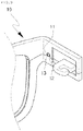
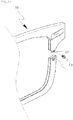
FIG.1 is an exploded perspective view showing an eyeglass frame coupling structure according to the present invention, wherein a connection portion of an eyeglass frame is in a separated state. -
FIG.2 is a perspective view showing the eyeglass frame coupling structure according to the present invention, wherein the connection portion of the eyeglass frame is in a connected state. -
FIG.3 is an exploded perspective view of a portion A ofFIG.1 . -
FIG.4 is a longitudinal sectional view showing the eyeglass frame coupling structure according to the present invention, wherein the connection portion of the eyeglass frame is in a separated state. -
FIG.5 is a longitudinal sectional view showing the eyeglass frame coupling structure according to the present invention, wherein the connection portion of the eyeglass frame is in a connected state. -
FIG. 6 is a cross-sectional view showing the eyeglass frame coupling structure according to the present invention, wherein the connection portion of the eyeglass frame is in a connected state. -
FIG.7 is a cross-sectional view showing the state before a fixing screw is completely fastened to the connection portion of the eyeglass frame. -
FIG.8 is a front view showing the eyeglass frame coupling structure according to the present invention, wherein the connection portion of the eyeglass frame is formed on a bridge of the eyeglasses. -
FIG. 9 is a perspective view showing the eyeglass frame coupling structure according to the present invention, wherein the connection portion of the eyeglass frame is formed on an end piece of the eyeglass frame. -
FIG.10 is an exploded perspective view showing the state where another type fixing screw is fastened to the connection portion of the eyeglass frame in the eyeglass frame coupling structure according to the present invention. -
FIG.11 is an exploded perspective view showing the state where the receiving portion and the protruding portion are changed in position in the eyeglass frame coupling structure according to the present invention. - As shown in
FIGS. 1 to 7 , an eyeglass frame coupling structure is configured wherein aneyeglass frame 10, which has an insertion groove formed along the inner edge thereof so as to fit the outer edge of a lens 1, is separably connected on a given portion thereof, and the eyeglass frame coupling structure includes: areceiving portion 11 having a receiving groove a formed open on one side rear surface of the separable connection portion thereof towards the connection portion and the rear side thereof, a fixing groove b formed on the bottom of the receiving groove a exposed to the rear side, and an engaging groove c formed on a surface that forms the outer peripheral side wall of the receiving groove a; a protrudingportion 12 having a protrusion d formed on the rear surface of the other side of the connection portion of theeyeglass frame 10, which abuts thereceiving portion 11, so as to be inserted into thereceiving portion 11, an engaging step e protruding outwardly from the outermost peripheral portion of the protrusion d in such a manner as to be inserted into the engaging groove c, and a screw hole f formed in the middle of the protrusion d in the forward/backward direction so as to communicate with the fixing groove b; and afixing screw 13 screw-fastened to the screw hole f of the protrudingportion 12 such that an end of thefixing screw 13 is inserted into the fixing groove b of thereceiving portion 11. - Under the above-mentioned configuration of the eyeglass frame coupling structure according to the present invention, the outer edge of the lens 1 is fitted to the insertion groove formed on the inner side of the
eyeglass frame 10, and if the protrudingportion 12 pushes toward thereceiving portion 11, the protrusion d is guided by the receiving groove a to allow the connection portion of theeyeglass frame 10 to move to a precisely set position. After that, the engaging step e of the protrudingportion 12 is inserted into the engaging groove c of thereceiving portion 11 to allow the movements of the connection portion of theeyeglass frame 10 to be limited in every direction. At this time, the screw hole f of the protrudingportion 12 is in the same line as the fixing groove b of thereceiving portion 11, and if thefixing screw 13 is screw-fastened to the screw hole f, the end of thefixing screw 13 is inserted into the fixing groove b to allow the horizontal movements of the connection portion of theeyeglass frame 10 to be limited, so that the coupling state of the receivingportion 11 and the protrudingportion 12 can be firmly maintained. - On the other hand, as shown in
FIGS. 4 and7 , if the fixing screw 3 is somewhat unfastened to separate the connection portion of theeyeglass frame 10, the end of thefixing screw 13 escapes from the fixing groove b and is fixed to the screw hole f of the protrudingportion 12, so that the connection portion of theeyeglass frame 10 can be separated into upper and lower parts. - That is, even if the
fixing screw 13 is completely unfastened from the screw hole f, thereceiving portion 11 and the protrudingportion 12 of theeyeglass frame 10 are separated from each other, so that the lens 1 can be easily detachably attached to theeyeglass frame 10. - In this case, the receiving groove a of the
receiving portion 11 is formed to the intermediate depth of the thickness of theeyeglass frame 10 from the rear surface of theeyeglass frame 10 in such a manner as to be open toward the connection portion of theeyeglass frame 10. Also, the receiving groove a is formed curved on the inner side thereof, and the engaging groove c is formed along the curved portion of the receiving groove c. - The protrusion d of the protruding
portion 12 has a thickness from the rear surface of the connection portion of theeyeglass frame 10 to the intermediate portion thereof in such a manner as to protrude toward thereceiving portion 11, and also, the protrusion d is formed curved with the same radius as the receiving groove a. - On the other hand, as shown in
FIG.8 , the connection portion of theeyeglass frame 10 in the eyeglass frame coupling structure according to the present invention may be formed on a portion of the center of theeyeglass frame 10 to which a bridge is coupled. Otherwise, as shown inFIG.9 , both side ends of theeyeglass frame 10 are separated into upper and lower parts, and the connection portion of the eyeglass frame coupling structure according to the present invention may be formed on a backwardly extended eyeglass frame portion. Of course, the connection portion of theeyeglass frame 10 may be formed on other portions thereof. - Further, the
fixing screw 13 has a concave head, and otherwise, as shown inFIG.10 , the screw hole f has an extended entrance, while thefixing screw 13 has a flat head, so that if thefixing screw 13 is fastened to the screw hole f, it has the same horizontal surface as theeyeglass frame 10. - According to the present invention, on the other hand, the side portions of the eyeglass frame connected to temples are separated into upper and lower parts, so that the receiving portion is formed on the upper part and the protruding portion on the lower part. According to another embodiment of the present invention, as shown in
FIG.11 , a protruding portion 12' is formed on the upper portion of the connection portion and a receiving portion 11' on the lower portion of the connection portion. - According to yet another embodiment (not shown) of the present invention, further, a portion or the whole of one side rear surface of an eyeglass frame connected laminatedly is incised to a given depth, so that an engaging groove is formed on a portion at which the step is formed, and a fixing groove is formed on the incised portion. Further, a portion or the whole of the other side front surface of the eyeglass frame connected laminatedly is incised, so that an engaging step inserted into the engaging groove is formed protruding from the outer periphery of the incised portion, and a screw hole is formed on the intermediate portion of the engaging step in such a manner as to communicate with the fixing groove.
| 1: lens | 10: eyeglass frame |
| 11: receiving portion | 12: protruding portion |
| 13: fixing screw | a: receiving groove |
| b: fixing groove | c: engaging groove |
| d: protrusion | e: engaging step |
| f: screw hole |
Claims (2)
- An eyeglass frame coupling structure comprising:a portion of an eyeglass frame 10 separably laminated on each other, the eyeglass frame 10 being adapted to fix the outer edge of a lens 1 thereto;a fixing groove b formed in a forward and backward direction on one side of the laminated portion of the eyeglass frame 10 and an engaging groove c formed in a traverse direction of the laminated portion of the eyeglass frame 10;a screw hole f and an engaging step e formed on the other side of the laminated portion of the eyeglass frame 10, the screw hole f communicating with the fixing groove b, and the engaging step e being inserted into the engaging groove c; anda fixing screw 13 screw-fastened to the screw hole f in such a manner where an end of the fixing screw 13 is just inserted into the fixing groove b.
- The eyeglass frame coupling structure according to claim 1, wherein a receiving groove a is formed open on one side rear surface of the laminated portion of the eyeglass frame 10 towards the laminated portion and the rear side thereof, so that the fixing groove is formed on the bottom of the receiving groove and the engaging groove c is formed on a surface that forms the outer peripheral side wall of the receiving groove a, and a protrusion d is formed on the rear surface of the other side of the laminated portion of the eyeglass frame 10 in such a manner as to be inserted into the receiving groove a, so that the engaging step e is formed protruding outwardly from the outermost peripheral portion of the protrusion d and the screw hole f is formed in the middle of the protrusion d.
Applications Claiming Priority (2)
| Application Number | Priority Date | Filing Date | Title |
|---|---|---|---|
| KR1020140033407A KR101568931B1 (en) | 2014-03-21 | 2014-03-21 | Structure of the combined glasses frame |
| PCT/KR2015/002718 WO2015142096A1 (en) | 2014-03-21 | 2015-03-20 | Eyeglass frame coupling structure |
Publications (3)
| Publication Number | Publication Date |
|---|---|
| EP3121642A1 true EP3121642A1 (en) | 2017-01-25 |
| EP3121642A4 EP3121642A4 (en) | 2017-11-15 |
| EP3121642B1 EP3121642B1 (en) | 2019-05-08 |
Family
ID=54144973
Family Applications (1)
| Application Number | Title | Priority Date | Filing Date |
|---|---|---|---|
| EP15764757.9A Active EP3121642B1 (en) | 2014-03-21 | 2015-03-20 | Eyeglass frame coupling structure |
Country Status (3)
| Country | Link |
|---|---|
| EP (1) | EP3121642B1 (en) |
| KR (1) | KR101568931B1 (en) |
| WO (1) | WO2015142096A1 (en) |
Families Citing this family (1)
| Publication number | Priority date | Publication date | Assignee | Title |
|---|---|---|---|---|
| KR102136175B1 (en) * | 2019-08-20 | 2020-07-21 | 박문순 | Customized eyeglasses frame |
Family Cites Families (11)
| Publication number | Priority date | Publication date | Assignee | Title |
|---|---|---|---|---|
| US2103421A (en) * | 1936-03-27 | 1937-12-28 | Bausch & Lomb | Ophthalmic mounting |
| JPS5458140U (en) * | 1977-09-30 | 1979-04-21 | ||
| KR20000002819U (en) * | 1998-07-04 | 2000-02-07 | 이재화 | Lens assembly device of metal glasses frame |
| JP2001133731A (en) * | 1999-11-05 | 2001-05-18 | Murai:Kk | Spectacles |
| US6099118A (en) * | 1999-12-01 | 2000-08-08 | Hwang; Woei-Jyh | Structure of eyeglasses |
| KR200199592Y1 (en) * | 2000-05-13 | 2000-10-02 | 김영호 | Connecting structure of temple for glasses |
| JP2003015088A (en) | 2001-06-29 | 2003-01-15 | Vision Megane:Kk | Spectacles |
| JP2003029214A (en) | 2001-07-19 | 2003-01-29 | Fukui Megane Kogyo Kk | Spectacle parts of structure integrated with brow endpiece and hinge |
| KR101099214B1 (en) * | 2009-08-12 | 2011-12-28 | 이재직 | Combined structure of spectacle frame and leg |
| KR200454400Y1 (en) * | 2009-08-21 | 2011-06-30 | 이상탁 | Structure of prefabricated hinge protrusion of eyeglass frame |
| FR2975791B1 (en) * | 2011-05-24 | 2013-05-31 | Guillaume Lefrancois | MOUNTING GLASSES WITHOUT SCREWS |
-
2014
- 2014-03-21 KR KR1020140033407A patent/KR101568931B1/en active Active
-
2015
- 2015-03-20 WO PCT/KR2015/002718 patent/WO2015142096A1/en not_active Ceased
- 2015-03-20 EP EP15764757.9A patent/EP3121642B1/en active Active
Also Published As
| Publication number | Publication date |
|---|---|
| WO2015142096A1 (en) | 2015-09-24 |
| EP3121642A4 (en) | 2017-11-15 |
| EP3121642B1 (en) | 2019-05-08 |
| KR20150109895A (en) | 2015-10-02 |
| KR101568931B1 (en) | 2015-11-12 |
Similar Documents
| Publication | Publication Date | Title |
|---|---|---|
| USD849825S1 (en) | Sport eyeglasses | |
| USD859512S1 (en) | Eyeglasses | |
| USD811381S1 (en) | Terminal | |
| USD870802S1 (en) | Sport eyeglasses | |
| USD935896S1 (en) | Wristwatch | |
| USD853878S1 (en) | Watch case | |
| USD869977S1 (en) | Watch dial | |
| USD842355S1 (en) | Eyeglass lens | |
| USD791277S1 (en) | Showerhead | |
| USD821486S1 (en) | Set of eyeglass components | |
| USD827690S1 (en) | Eyeglass lens | |
| USD809042S1 (en) | Eyeglass lens | |
| USD867439S1 (en) | Eyewear | |
| USD990371S1 (en) | Fixing part for drone | |
| USD858314S1 (en) | Watchcase | |
| USD958292S1 (en) | Shower head | |
| USD745081S1 (en) | Swimming goggles | |
| USD922160S1 (en) | Apple corer | |
| USD891613S1 (en) | Adapter collet | |
| USD1049209S1 (en) | Spectacle frame | |
| USD842130S1 (en) | Clock | |
| USD879569S1 (en) | Corkscrew | |
| USD913837S1 (en) | Bracelet | |
| USD898749S1 (en) | USB memory device | |
| USD882673S1 (en) | Eyeglasses |
Legal Events
| Date | Code | Title | Description |
|---|---|---|---|
| STAA | Information on the status of an ep patent application or granted ep patent |
Free format text: STATUS: THE INTERNATIONAL PUBLICATION HAS BEEN MADE |
|
| PUAI | Public reference made under article 153(3) epc to a published international application that has entered the european phase |
Free format text: ORIGINAL CODE: 0009012 |
|
| STAA | Information on the status of an ep patent application or granted ep patent |
Free format text: STATUS: REQUEST FOR EXAMINATION WAS MADE |
|
| 17P | Request for examination filed |
Effective date: 20161021 |
|
| AK | Designated contracting states |
Kind code of ref document: A1 Designated state(s): AL AT BE BG CH CY CZ DE DK EE ES FI FR GB GR HR HU IE IS IT LI LT LU LV MC MK MT NL NO PL PT RO RS SE SI SK SM TR |
|
| AX | Request for extension of the european patent |
Extension state: BA ME |
|
| DAV | Request for validation of the european patent (deleted) | ||
| DAX | Request for extension of the european patent (deleted) | ||
| REG | Reference to a national code |
Ref country code: DE Ref legal event code: R079 Ref document number: 602015029916 Country of ref document: DE Free format text: PREVIOUS MAIN CLASS: G02C0001060000 Ipc: G02C0001080000 |
|
| A4 | Supplementary search report drawn up and despatched |
Effective date: 20171016 |
|
| RIC1 | Information provided on ipc code assigned before grant |
Ipc: G02C 1/08 20060101AFI20171010BHEP |
|
| GRAP | Despatch of communication of intention to grant a patent |
Free format text: ORIGINAL CODE: EPIDOSNIGR1 |
|
| STAA | Information on the status of an ep patent application or granted ep patent |
Free format text: STATUS: GRANT OF PATENT IS INTENDED |
|
| INTG | Intention to grant announced |
Effective date: 20181115 |
|
| GRAS | Grant fee paid |
Free format text: ORIGINAL CODE: EPIDOSNIGR3 |
|
| GRAA | (expected) grant |
Free format text: ORIGINAL CODE: 0009210 |
|
| STAA | Information on the status of an ep patent application or granted ep patent |
Free format text: STATUS: THE PATENT HAS BEEN GRANTED |
|
| AK | Designated contracting states |
Kind code of ref document: B1 Designated state(s): AL AT BE BG CH CY CZ DE DK EE ES FI FR GB GR HR HU IE IS IT LI LT LU LV MC MK MT NL NO PL PT RO RS SE SI SK SM TR |
|
| REG | Reference to a national code |
Ref country code: GB Ref legal event code: FG4D |
|
| REG | Reference to a national code |
Ref country code: CH Ref legal event code: EP Ref country code: AT Ref legal event code: REF Ref document number: 1131100 Country of ref document: AT Kind code of ref document: T Effective date: 20190515 |
|
| REG | Reference to a national code |
Ref country code: DE Ref legal event code: R096 Ref document number: 602015029916 Country of ref document: DE Ref country code: IE Ref legal event code: FG4D |
|
| REG | Reference to a national code |
Ref country code: NL Ref legal event code: MP Effective date: 20190508 |
|
| REG | Reference to a national code |
Ref country code: LT Ref legal event code: MG4D |
|
| PG25 | Lapsed in a contracting state [announced via postgrant information from national office to epo] |
Ref country code: PT Free format text: LAPSE BECAUSE OF FAILURE TO SUBMIT A TRANSLATION OF THE DESCRIPTION OR TO PAY THE FEE WITHIN THE PRESCRIBED TIME-LIMIT Effective date: 20190908 Ref country code: ES Free format text: LAPSE BECAUSE OF FAILURE TO SUBMIT A TRANSLATION OF THE DESCRIPTION OR TO PAY THE FEE WITHIN THE PRESCRIBED TIME-LIMIT Effective date: 20190508 Ref country code: SE Free format text: LAPSE BECAUSE OF FAILURE TO SUBMIT A TRANSLATION OF THE DESCRIPTION OR TO PAY THE FEE WITHIN THE PRESCRIBED TIME-LIMIT Effective date: 20190508 Ref country code: AL Free format text: LAPSE BECAUSE OF FAILURE TO SUBMIT A TRANSLATION OF THE DESCRIPTION OR TO PAY THE FEE WITHIN THE PRESCRIBED TIME-LIMIT Effective date: 20190508 Ref country code: NL Free format text: LAPSE BECAUSE OF FAILURE TO SUBMIT A TRANSLATION OF THE DESCRIPTION OR TO PAY THE FEE WITHIN THE PRESCRIBED TIME-LIMIT Effective date: 20190508 Ref country code: FI Free format text: LAPSE BECAUSE OF FAILURE TO SUBMIT A TRANSLATION OF THE DESCRIPTION OR TO PAY THE FEE WITHIN THE PRESCRIBED TIME-LIMIT Effective date: 20190508 Ref country code: NO Free format text: LAPSE BECAUSE OF FAILURE TO SUBMIT A TRANSLATION OF THE DESCRIPTION OR TO PAY THE FEE WITHIN THE PRESCRIBED TIME-LIMIT Effective date: 20190808 Ref country code: HR Free format text: LAPSE BECAUSE OF FAILURE TO SUBMIT A TRANSLATION OF THE DESCRIPTION OR TO PAY THE FEE WITHIN THE PRESCRIBED TIME-LIMIT Effective date: 20190508 Ref country code: LT Free format text: LAPSE BECAUSE OF FAILURE TO SUBMIT A TRANSLATION OF THE DESCRIPTION OR TO PAY THE FEE WITHIN THE PRESCRIBED TIME-LIMIT Effective date: 20190508 |
|
| PG25 | Lapsed in a contracting state [announced via postgrant information from national office to epo] |
Ref country code: RS Free format text: LAPSE BECAUSE OF FAILURE TO SUBMIT A TRANSLATION OF THE DESCRIPTION OR TO PAY THE FEE WITHIN THE PRESCRIBED TIME-LIMIT Effective date: 20190508 Ref country code: GR Free format text: LAPSE BECAUSE OF FAILURE TO SUBMIT A TRANSLATION OF THE DESCRIPTION OR TO PAY THE FEE WITHIN THE PRESCRIBED TIME-LIMIT Effective date: 20190809 Ref country code: BG Free format text: LAPSE BECAUSE OF FAILURE TO SUBMIT A TRANSLATION OF THE DESCRIPTION OR TO PAY THE FEE WITHIN THE PRESCRIBED TIME-LIMIT Effective date: 20190808 Ref country code: LV Free format text: LAPSE BECAUSE OF FAILURE TO SUBMIT A TRANSLATION OF THE DESCRIPTION OR TO PAY THE FEE WITHIN THE PRESCRIBED TIME-LIMIT Effective date: 20190508 |
|
| REG | Reference to a national code |
Ref country code: AT Ref legal event code: MK05 Ref document number: 1131100 Country of ref document: AT Kind code of ref document: T Effective date: 20190508 |
|
| PG25 | Lapsed in a contracting state [announced via postgrant information from national office to epo] |
Ref country code: AT Free format text: LAPSE BECAUSE OF FAILURE TO SUBMIT A TRANSLATION OF THE DESCRIPTION OR TO PAY THE FEE WITHIN THE PRESCRIBED TIME-LIMIT Effective date: 20190508 Ref country code: DK Free format text: LAPSE BECAUSE OF FAILURE TO SUBMIT A TRANSLATION OF THE DESCRIPTION OR TO PAY THE FEE WITHIN THE PRESCRIBED TIME-LIMIT Effective date: 20190508 Ref country code: EE Free format text: LAPSE BECAUSE OF FAILURE TO SUBMIT A TRANSLATION OF THE DESCRIPTION OR TO PAY THE FEE WITHIN THE PRESCRIBED TIME-LIMIT Effective date: 20190508 Ref country code: CZ Free format text: LAPSE BECAUSE OF FAILURE TO SUBMIT A TRANSLATION OF THE DESCRIPTION OR TO PAY THE FEE WITHIN THE PRESCRIBED TIME-LIMIT Effective date: 20190508 Ref country code: RO Free format text: LAPSE BECAUSE OF FAILURE TO SUBMIT A TRANSLATION OF THE DESCRIPTION OR TO PAY THE FEE WITHIN THE PRESCRIBED TIME-LIMIT Effective date: 20190508 Ref country code: SK Free format text: LAPSE BECAUSE OF FAILURE TO SUBMIT A TRANSLATION OF THE DESCRIPTION OR TO PAY THE FEE WITHIN THE PRESCRIBED TIME-LIMIT Effective date: 20190508 |
|
| REG | Reference to a national code |
Ref country code: DE Ref legal event code: R097 Ref document number: 602015029916 Country of ref document: DE |
|
| PG25 | Lapsed in a contracting state [announced via postgrant information from national office to epo] |
Ref country code: IT Free format text: LAPSE BECAUSE OF FAILURE TO SUBMIT A TRANSLATION OF THE DESCRIPTION OR TO PAY THE FEE WITHIN THE PRESCRIBED TIME-LIMIT Effective date: 20190508 Ref country code: SM Free format text: LAPSE BECAUSE OF FAILURE TO SUBMIT A TRANSLATION OF THE DESCRIPTION OR TO PAY THE FEE WITHIN THE PRESCRIBED TIME-LIMIT Effective date: 20190508 |
|
| PLBE | No opposition filed within time limit |
Free format text: ORIGINAL CODE: 0009261 |
|
| STAA | Information on the status of an ep patent application or granted ep patent |
Free format text: STATUS: NO OPPOSITION FILED WITHIN TIME LIMIT |
|
| PG25 | Lapsed in a contracting state [announced via postgrant information from national office to epo] |
Ref country code: TR Free format text: LAPSE BECAUSE OF FAILURE TO SUBMIT A TRANSLATION OF THE DESCRIPTION OR TO PAY THE FEE WITHIN THE PRESCRIBED TIME-LIMIT Effective date: 20190508 |
|
| 26N | No opposition filed |
Effective date: 20200211 |
|
| PG25 | Lapsed in a contracting state [announced via postgrant information from national office to epo] |
Ref country code: PL Free format text: LAPSE BECAUSE OF FAILURE TO SUBMIT A TRANSLATION OF THE DESCRIPTION OR TO PAY THE FEE WITHIN THE PRESCRIBED TIME-LIMIT Effective date: 20190508 |
|
| PG25 | Lapsed in a contracting state [announced via postgrant information from national office to epo] |
Ref country code: SI Free format text: LAPSE BECAUSE OF FAILURE TO SUBMIT A TRANSLATION OF THE DESCRIPTION OR TO PAY THE FEE WITHIN THE PRESCRIBED TIME-LIMIT Effective date: 20190508 |
|
| PG25 | Lapsed in a contracting state [announced via postgrant information from national office to epo] |
Ref country code: MC Free format text: LAPSE BECAUSE OF FAILURE TO SUBMIT A TRANSLATION OF THE DESCRIPTION OR TO PAY THE FEE WITHIN THE PRESCRIBED TIME-LIMIT Effective date: 20190508 |
|
| REG | Reference to a national code |
Ref country code: CH Ref legal event code: PL |
|
| REG | Reference to a national code |
Ref country code: BE Ref legal event code: MM Effective date: 20200331 |
|
| PG25 | Lapsed in a contracting state [announced via postgrant information from national office to epo] |
Ref country code: LU Free format text: LAPSE BECAUSE OF NON-PAYMENT OF DUE FEES Effective date: 20200320 |
|
| PG25 | Lapsed in a contracting state [announced via postgrant information from national office to epo] |
Ref country code: CH Free format text: LAPSE BECAUSE OF NON-PAYMENT OF DUE FEES Effective date: 20200331 Ref country code: LI Free format text: LAPSE BECAUSE OF NON-PAYMENT OF DUE FEES Effective date: 20200331 Ref country code: IE Free format text: LAPSE BECAUSE OF NON-PAYMENT OF DUE FEES Effective date: 20200320 |
|
| PG25 | Lapsed in a contracting state [announced via postgrant information from national office to epo] |
Ref country code: BE Free format text: LAPSE BECAUSE OF NON-PAYMENT OF DUE FEES Effective date: 20200331 |
|
| PG25 | Lapsed in a contracting state [announced via postgrant information from national office to epo] |
Ref country code: MT Free format text: LAPSE BECAUSE OF FAILURE TO SUBMIT A TRANSLATION OF THE DESCRIPTION OR TO PAY THE FEE WITHIN THE PRESCRIBED TIME-LIMIT Effective date: 20190508 Ref country code: CY Free format text: LAPSE BECAUSE OF FAILURE TO SUBMIT A TRANSLATION OF THE DESCRIPTION OR TO PAY THE FEE WITHIN THE PRESCRIBED TIME-LIMIT Effective date: 20190508 |
|
| PG25 | Lapsed in a contracting state [announced via postgrant information from national office to epo] |
Ref country code: MK Free format text: LAPSE BECAUSE OF FAILURE TO SUBMIT A TRANSLATION OF THE DESCRIPTION OR TO PAY THE FEE WITHIN THE PRESCRIBED TIME-LIMIT Effective date: 20190508 Ref country code: IS Free format text: LAPSE BECAUSE OF FAILURE TO SUBMIT A TRANSLATION OF THE DESCRIPTION OR TO PAY THE FEE WITHIN THE PRESCRIBED TIME-LIMIT Effective date: 20190908 |
|
| PGFP | Annual fee paid to national office [announced via postgrant information from national office to epo] |
Ref country code: DE Payment date: 20250328 Year of fee payment: 11 |
|
| PGFP | Annual fee paid to national office [announced via postgrant information from national office to epo] |
Ref country code: GB Payment date: 20260317 Year of fee payment: 12 |
|
| PGFP | Annual fee paid to national office [announced via postgrant information from national office to epo] |
Ref country code: FR Payment date: 20260319 Year of fee payment: 12 |