EP3121559A1 - Method for measuring thickness of carbon fiber components using ultrasounds - Google Patents
Method for measuring thickness of carbon fiber components using ultrasounds Download PDFInfo
- Publication number
- EP3121559A1 EP3121559A1 EP15382384.4A EP15382384A EP3121559A1 EP 3121559 A1 EP3121559 A1 EP 3121559A1 EP 15382384 A EP15382384 A EP 15382384A EP 3121559 A1 EP3121559 A1 EP 3121559A1
- Authority
- EP
- European Patent Office
- Prior art keywords
- thickness
- component
- ultrasound
- carbon fiber
- measuring
- Prior art date
- Legal status (The legal status is an assumption and is not a legal conclusion. Google has not performed a legal analysis and makes no representation as to the accuracy of the status listed.)
- Granted
Links
Images


Classifications
-
- G—PHYSICS
- G01—MEASURING; TESTING
- G01B—MEASURING LENGTH, THICKNESS OR SIMILAR LINEAR DIMENSIONS; MEASURING ANGLES; MEASURING AREAS; MEASURING IRREGULARITIES OF SURFACES OR CONTOURS
- G01B17/00—Measuring arrangements characterised by the use of infrasonic, sonic or ultrasonic vibrations
- G01B17/02—Measuring arrangements characterised by the use of infrasonic, sonic or ultrasonic vibrations for measuring thickness
-
- G—PHYSICS
- G01—MEASURING; TESTING
- G01N—INVESTIGATING OR ANALYSING MATERIALS BY DETERMINING THEIR CHEMICAL OR PHYSICAL PROPERTIES
- G01N29/00—Investigating or analysing materials by the use of ultrasonic, sonic or infrasonic waves; Visualisation of the interior of objects by transmitting ultrasonic or sonic waves through the object
- G01N29/04—Analysing solids
- G01N29/07—Analysing solids by measuring propagation velocity or propagation time of acoustic waves
-
- G—PHYSICS
- G01—MEASURING; TESTING
- G01N—INVESTIGATING OR ANALYSING MATERIALS BY DETERMINING THEIR CHEMICAL OR PHYSICAL PROPERTIES
- G01N29/00—Investigating or analysing materials by the use of ultrasonic, sonic or infrasonic waves; Visualisation of the interior of objects by transmitting ultrasonic or sonic waves through the object
- G01N29/22—Details, e.g. general constructional or apparatus details
- G01N29/30—Arrangements for calibrating or comparing, e.g. with standard objects
-
- G—PHYSICS
- G01—MEASURING; TESTING
- G01N—INVESTIGATING OR ANALYSING MATERIALS BY DETERMINING THEIR CHEMICAL OR PHYSICAL PROPERTIES
- G01N2291/00—Indexing codes associated with group G01N29/00
- G01N2291/01—Indexing codes associated with the measuring variable
- G01N2291/011—Velocity or travel time
-
- G—PHYSICS
- G01—MEASURING; TESTING
- G01N—INVESTIGATING OR ANALYSING MATERIALS BY DETERMINING THEIR CHEMICAL OR PHYSICAL PROPERTIES
- G01N2291/00—Indexing codes associated with group G01N29/00
- G01N2291/02—Indexing codes associated with the analysed material
- G01N2291/023—Solids
- G01N2291/0231—Composite or layered materials
-
- G—PHYSICS
- G01—MEASURING; TESTING
- G01N—INVESTIGATING OR ANALYSING MATERIALS BY DETERMINING THEIR CHEMICAL OR PHYSICAL PROPERTIES
- G01N2291/00—Indexing codes associated with group G01N29/00
- G01N2291/02—Indexing codes associated with the analysed material
- G01N2291/023—Solids
- G01N2291/0235—Plastics; polymers; soft materials, e.g. rubber
-
- G—PHYSICS
- G01—MEASURING; TESTING
- G01N—INVESTIGATING OR ANALYSING MATERIALS BY DETERMINING THEIR CHEMICAL OR PHYSICAL PROPERTIES
- G01N2291/00—Indexing codes associated with group G01N29/00
- G01N2291/02—Indexing codes associated with the analysed material
- G01N2291/028—Material parameters
- G01N2291/02854—Length, thickness
Definitions
- the present invention refers in general to ultrasonic testing techniques for quality dimensional measurements.
- the invention refers to a method for measuring thickness using ultrasounds in carbon fiber based components.
- An object of the invention is to provide thickness measuring method with enhanced accuracy and simplicity, and which can be applied to heterogeneous composite components formed by several types of materials.
- ultrasonic measurements provide the thickness of a component by measuring the time (t) that an ultrasonic signal takes to propagate across a component (1) and return to the ultrasound equipment (2).
- some aircraft components like wings skin covers, are typically formed by several layers of different materials, like carbon fiber, copper mesh, adhesive layers, excess of resin, etc., so that the total thickness of the component in a specific area, is the carbon fiber thickness plus the thickness of the other materials.
- the present invention is defined in the attached independent claim and it overcomes the above-mentioned drawbacks of the prior art, by providing an automatic method for measuring thickness of heterogeneous components in which carbon fiber is the main component with variable thickness and it additionally integrates at least a second material different with constant thickness, like a copper mesh, adhesive layers, fiber glass, etc.
- an unique ultrasound speed is calculated throughout all of the component and corresponding to the material of variable thickness, capable of accurately measuring the thickness of the carbon fiber, but fails due to the different propagation speed of the second material and disturbance caused by the surface roughness.
- both the thickness of the second material and surface roughness are constant in all areas, so the error obtained is constant too, and the calculation of this error allows to apply a precise correction on the results.
- the method comprises the steps of measuring the maximum and minimum real thickness of the component, that is, measurement of the real thickness of the thicker part and the real thickness of the thinner part of the component. These measurements are carried out conventionally by means of a mechanical thickness measurement device, such as a calipper or a micrometer for example (or any another way in order to know the real thickness).
- a mechanical thickness measurement device such as a calipper or a micrometer for example (or any another way in order to know the real thickness).
- an automatic ultrasound equipment is used to measure the time between when the signal is output until the echo is received after bouncing at the bottom of each thickness part measured with micrometer in the previously step.
- an automatic ultrasound measurement equipment is set at the calculated ultrasound test speed, and total thickness measurements are taken through an entire component using the same calculated ultrasound test speed.
- the calculated thickness correction value is applied to each of the measuring total thickness for each part of the component, to determine a corrected carbon fiber thickness for each part.
- the method of the invention is suitable for measuring carbon fiber thickness, in any carbon fiber component (preferably Carbon Fiber Reinforced Plastic), even like the one shown in figure 2 , having parts with different thickness (3a,3b,3c) and integrating at least one layer (4) of a second material, different than carbon fiber.
- this second material is a copper mesh having a constant thickness though out the different parts of the component.
- the real thickness of the thicker part (3a) and the real thickness of the thinner part (3c), are measured, with micrometer.
- An optimum ultrasound test speed is calculated for which the difference between the measurement error at the maximum real thickness and the measurement error at the minimum real thickness of the component, is similar
- Figure 3 shows the accuracy of several ultrasound speeds for a range of thickness 2 - 18. It can be noted in the graph that an ultrasound speed of 2955 m/s is the optimum speed, since it is the one providing a similar error along the thickness of the component.
- a thickness correction value (X) is calculated for each part (3a,3b,3c) of the component with different thickness.
- an ultrasound test speed (Y) is also calculated from said thickness correction value, said measured times, and said measured maximum and minimum real thickness.
- an automatic ultrasound measurement equipment is set with the calculated ultrasound test speed (Y), and using this speed he total thickness of each of the parts of the component is measured. Then, the calculated thickness correction value (X) is applied to each of the measured total thickness of each part, to obtain a corrected carbon fiber thickness for each part of the component.
- Figure 4 shows the great accuracy achieved with the method of the invention, wherein it can be noted that different between the real thickness (caliper value column), and the thickness obtained by the method of the invention (calculated thickness column), is less 0.52 % in this particular example.
Landscapes
- Physics & Mathematics (AREA)
- General Physics & Mathematics (AREA)
- Health & Medical Sciences (AREA)
- Life Sciences & Earth Sciences (AREA)
- Chemical & Material Sciences (AREA)
- Analytical Chemistry (AREA)
- Biochemistry (AREA)
- General Health & Medical Sciences (AREA)
- Immunology (AREA)
- Pathology (AREA)
- Acoustics & Sound (AREA)
- Length Measuring Devices Characterised By Use Of Acoustic Means (AREA)
Abstract
Description
- The present invention refers in general to ultrasonic testing techniques for quality dimensional measurements.
- More specifically, the invention refers to a method for measuring thickness using ultrasounds in carbon fiber based components.
- An object of the invention is to provide thickness measuring method with enhanced accuracy and simplicity, and which can be applied to heterogeneous composite components formed by several types of materials.
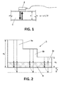
- It is known that ultrasonic measurements provide the thickness of a component by measuring the time (t) that an ultrasonic signal takes to propagate across a component (1) and return to the ultrasound equipment (2).
Figure 1 shows this technique, wherein the thickness of the component (e) is calculated by the formula e = v · t / 2, wherein (v) is the ultrasound speed set at the ultrasound emitter (2). - Since the measurement accuracy of each ultrasound speed is different for different thickness to be measured, standard use of ultrasonic automatic equipment for measuring the thickness of a component having areas of different thickness, conventionally requires several adjustments of the generated ultrasonic speed (v) for maximum and minimum thickness of that particular component, in order to select a ultrasonic speed which provides an acceptable accuracy for each thickness range. Due to these readjustments, the measurement process is slow and complex.
- Additionally, some aircraft components like wings skin covers, are typically formed by several layers of different materials, like carbon fiber, copper mesh, adhesive layers, excess of resin, etc., so that the total thickness of the component in a specific area, is the carbon fiber thickness plus the thickness of the other materials.
- Since ultrasound propagation speed changes for each type of material (see
figure 2 ), the lack of homogeneity of these components, the surface roughness, in addition to the different thicknesses of the component, causes that the accuracy required for dimensional measurements, is not guaranteed. Currently, the error caused by the additional materials different than carbon fiber is disregarded. - The present invention is defined in the attached independent claim and it overcomes the above-mentioned drawbacks of the prior art, by providing an automatic method for measuring thickness of heterogeneous components in which carbon fiber is the main component with variable thickness and it additionally integrates at least a second material different with constant thickness, like a copper mesh, adhesive layers, fiber glass, etc.
- According to the invention, an unique ultrasound speed is calculated throughout all of the component and corresponding to the material of variable thickness, capable of accurately measuring the thickness of the carbon fiber, but fails due to the different propagation speed of the second material and disturbance caused by the surface roughness. As both the thickness of the second material and surface roughness are constant in all areas, so the error obtained is constant too, and the calculation of this error allows to apply a precise correction on the results.
- The method comprises the steps of measuring the maximum and minimum real thickness of the component, that is, measurement of the real thickness of the thicker part and the real thickness of the thinner part of the component. These measurements are carried out conventionally by means of a mechanical thickness measurement device, such as a calipper or a micrometer for example (or any another way in order to know the real thickness).
- Then, an automatic ultrasound equipment is used to measure the time between when the signal is output until the echo is received after bouncing at the bottom of each thickness part measured with micrometer in the previously step.
- By the real value of the maximum and minimum thickness and the time spent by the signal in crossing them, we can propose an equation that allows us to calculate the ultrasound test speed and the thickness correction factor.
- Then, an automatic ultrasound measurement equipment is set at the calculated ultrasound test speed, and total thickness measurements are taken through an entire component using the same calculated ultrasound test speed.
- Finally, the calculated thickness correction value is applied to each of the measuring total thickness for each part of the component, to determine a corrected carbon fiber thickness for each part.
- Some advantages of the invention are the followings:
- since only one speed setting is needed at the beginning of the process, the measuring process is greatly simplified.
- Improved accuracy. In the range of 0-18mm of thickness in calibration block, the method of the invention provides a maximum of +0.02mm/-0.04mm of uncertainty in the measurement. Existing methods without readjustment provides in the same range and calibration block +0.09mm/-0.15mm of uncertainty.
- Preferred embodiments of the invention, are henceforth described with reference to the accompanying drawings, wherein:
-
Figure 1 .- shows a schematic representation of the traditional process for thickness measurement using ultrasounds. -
Figure 2 .- shows a schematic representation of an ultrasound thickness measurement in a carbon fiber component (3) formed by parts with different thickness (3a,3b,3c) and incorporating a second material (4), as a copper mesh, adhesive etc. The arrows in the figure represent the different ultrasound propagation speed for each material, and the error "X" caused in the carbon fiber thickness measurement due to the different ultrasonic speed in the second material. -
Figure 3 .- The graph shows the problem of having to use different speeds and lack of precision offered, compared with the solution that allow the use of a single speed and greater accuracy for a thickness range of 2 - 18 mm. -
Figure 4 .- shows a table containing an example of calculated and measured data to demonstrate the accuracy of the carbon fiber measurement method of the invention. - The method of the invention is suitable for measuring carbon fiber thickness, in any carbon fiber component (preferably Carbon Fiber Reinforced Plastic), even like the one shown in
figure 2 , having parts with different thickness (3a,3b,3c) and integrating at least one layer (4) of a second material, different than carbon fiber. Typically, in a wing skin cover of an aircraft, this second material is a copper mesh having a constant thickness though out the different parts of the component. - The real thickness of the thicker part (3a) and the real thickness of the thinner part (3c), are measured, with micrometer.
- An optimum ultrasound test speed is calculated for which the difference between the measurement error at the maximum real thickness and the measurement error at the minimum real thickness of the component, is similar
-
Figure 3 shows the accuracy of several ultrasound speeds for a range of thickness 2 - 18. It can be noted in the graph that an ultrasound speed of 2955 m/s is the optimum speed, since it is the one providing a similar error along the thickness of the component. - On the other hand, two time measures are taken, one is the time that the ultrasound takes to propagate across the thicker component part, and a second one for the time that the ultrasound takes to propagate across the thinner component part.
- Then, a thickness correction value (X) is calculated for each part (3a,3b,3c) of the component with different thickness. Additionally, an ultrasound test speed (Y) is also calculated from said thickness correction value, said measured times, and said measured maximum and minimum real thickness.
- The process for calculating these two parameters (X),(Y) is describe below, wherein:
- Y= unique ultrasound test speed
- X= thickness correction value
- e1= measure by micrometer the real thickness of the thicker part of the component e2= measure by micrometer the real thickness of the thinner part of the component
- t1= time that the ultrasound takes to propagate across the thicker part of the component.
- t2= time that the ultrasound takes to propagate across the thinner part of the component.
- Knowing that e = v · t, then :


- We obtain the value of the two parameters:


- That is, we obtain a common calculated ultrasound test speed (Y) and a thickness correction value (X) for all the parts of the component with different thickness and materials configuration.
- In the case of
figure 2 , since the copper mesh thickness is constant throughout all the parts of the component, the value of (X) is the same for all the parts. - Finally, an automatic ultrasound measurement equipment is set with the calculated ultrasound test speed (Y), and using this speed he total thickness of each of the parts of the component is measured. Then, the calculated thickness correction value (X) is applied to each of the measured total thickness of each part, to obtain a corrected carbon fiber thickness for each part of the component.
-
Figure 4 shows the great accuracy achieved with the method of the invention, wherein it can be noted that different between the real thickness (caliper value column), and the thickness obtained by the method of the invention (calculated thickness column), is less 0.52 % in this particular example.
Claims (5)
- Method for measuring carbon fiber thickness, in a carbon fiber component having parts with different thickness and integrating at least a second material, the method comprising the steps of:measuring with micrometer the maximum and minimum real thickness of the component,measuring with automatic ultrasonic equipment, the time that an ultrasound takes to propagate across the component part with maximum and the component part with minimum thickness,calculating an ultrasonic test speed and a thickness correction value for the component,wherein said thickness correction value and an optimum ultrasound test speed are determined using the times that the ultrasound takes to propagate across the component part with maximum and the component part with minimum thickness, and the maximum and minimum measured real thickness,measuring total thickness of each of the parts of the component, using ultrasounds with the same calculated ultrasound test speed,and applying the thickness correction value to each of the measuring total thickness of each part, to determine a corrected carbon fiber thickness for each part.
- Method according to claim 1 or 3, wherein the real maximum and minimum thickness of the component is measured with a mechanical thickness measurement device.
- Method according to any of the preceding claims, wherein the thickness of the second material is constant though out the different parts of the component.
- Method according to any of the preceding claims, wherein the carbon fiber is a Carbon Fiber Reinforced Plastic.
- Method according to any of the preceding claims, wherein the ultrasound is generated by an automatic ultrasound measurement equipment, set at the calculated ultrasound test speed.
Priority Applications (3)
| Application Number | Priority Date | Filing Date | Title |
|---|---|---|---|
| ES15382384.4T ES2684756T3 (en) | 2015-07-24 | 2015-07-24 | Carbon fiber component thickness measurement procedure using ultrasound |
| EP15382384.4A EP3121559B1 (en) | 2015-07-24 | 2015-07-24 | Method for measuring thickness of carbon fiber components using ultrasounds |
| US15/216,852 US10359278B2 (en) | 2015-07-24 | 2016-07-22 | Method for measuring thickness of carbon fiber components using ultrasounds |
Applications Claiming Priority (1)
| Application Number | Priority Date | Filing Date | Title |
|---|---|---|---|
| EP15382384.4A EP3121559B1 (en) | 2015-07-24 | 2015-07-24 | Method for measuring thickness of carbon fiber components using ultrasounds |
Publications (2)
| Publication Number | Publication Date |
|---|---|
| EP3121559A1 true EP3121559A1 (en) | 2017-01-25 |
| EP3121559B1 EP3121559B1 (en) | 2018-05-23 |
Family
ID=53758163
Family Applications (1)
| Application Number | Title | Priority Date | Filing Date |
|---|---|---|---|
| EP15382384.4A Active EP3121559B1 (en) | 2015-07-24 | 2015-07-24 | Method for measuring thickness of carbon fiber components using ultrasounds |
Country Status (3)
| Country | Link |
|---|---|
| US (1) | US10359278B2 (en) |
| EP (1) | EP3121559B1 (en) |
| ES (1) | ES2684756T3 (en) |
Families Citing this family (3)
| Publication number | Priority date | Publication date | Assignee | Title |
|---|---|---|---|---|
| ES2869351T3 (en) * | 2018-08-30 | 2021-10-25 | Airbus Operations Slu | Reference block for ultrasonic shear wave calibration |
| CN114509813B (en) * | 2022-03-03 | 2022-09-23 | 中国科学院地理科学与资源研究所 | Method, device and electronic device for determining thickness of coal seam based on slot wave |
| CN120232506A (en) * | 2025-05-30 | 2025-07-01 | 零声科技(苏州)有限公司 | Ultrasonic sound velocity calibration method, thickness gauge, terminal equipment and storable medium |
Citations (3)
| Publication number | Priority date | Publication date | Assignee | Title |
|---|---|---|---|---|
| JPS58169016A (en) * | 1982-03-31 | 1983-10-05 | Nippon Kokan Kk <Nkk> | Calibrating method of measuring device for pipe thickness |
| US5448915A (en) * | 1993-09-02 | 1995-09-12 | Hughes Aircraft Company | Method for improving the accuracy of ultrasonic thickness measurements by calibrating for surface finish |
| US20110232360A1 (en) * | 2010-03-25 | 2011-09-29 | Deangelo Paul Joseph | Automatic calibration error detection for ultrasonic inspection devices |
Family Cites Families (6)
| Publication number | Priority date | Publication date | Assignee | Title |
|---|---|---|---|---|
| US5163027A (en) * | 1992-03-20 | 1992-11-10 | Lockheed Corporation | Calibration block and method for an ultrasonic system |
| US7076992B2 (en) * | 2003-11-06 | 2006-07-18 | Stephen John Greelish | Method and apparatus for calibrating position and thickness in acoustic hull testing |
| US7216544B2 (en) * | 2005-03-25 | 2007-05-15 | The Boeing Company | Ultrasonic inspection reference standard for composite Materials |
| US7762120B2 (en) * | 2005-12-01 | 2010-07-27 | The Boeing Company | Tapered ultrasonic reference standard |
| JP6126497B2 (en) * | 2013-08-30 | 2017-05-10 | 川崎重工業株式会社 | Ultrasonic flaw detector and method for operating ultrasonic flaw detector |
| US9737284B2 (en) * | 2014-10-23 | 2017-08-22 | Korea Research Institute Of Standards And Science | Phantom for measuring thickness of thin layer using ultrasonic imaging device and method of using thereof |
-
2015
- 2015-07-24 EP EP15382384.4A patent/EP3121559B1/en active Active
- 2015-07-24 ES ES15382384.4T patent/ES2684756T3/en active Active
-
2016
- 2016-07-22 US US15/216,852 patent/US10359278B2/en active Active
Patent Citations (3)
| Publication number | Priority date | Publication date | Assignee | Title |
|---|---|---|---|---|
| JPS58169016A (en) * | 1982-03-31 | 1983-10-05 | Nippon Kokan Kk <Nkk> | Calibrating method of measuring device for pipe thickness |
| US5448915A (en) * | 1993-09-02 | 1995-09-12 | Hughes Aircraft Company | Method for improving the accuracy of ultrasonic thickness measurements by calibrating for surface finish |
| US20110232360A1 (en) * | 2010-03-25 | 2011-09-29 | Deangelo Paul Joseph | Automatic calibration error detection for ultrasonic inspection devices |
Non-Patent Citations (1)
| Title |
|---|
| SCHINDEL D W ET AL: "Through-thickness characterization of solids by wideband air-coupled ultrasound", ULTRASONICS, IPC SCIENCE AND TECHNOLOGY PRESS LTD. GUILDFORD, GB, vol. 33, no. 1, 1 January 1995 (1995-01-01), pages 11 - 17, XP004035715, ISSN: 0041-624X, DOI: 10.1016/0041-624X(95)00011-Q * |
Also Published As
| Publication number | Publication date |
|---|---|
| ES2684756T3 (en) | 2018-10-04 |
| US20170023360A1 (en) | 2017-01-26 |
| US10359278B2 (en) | 2019-07-23 |
| EP3121559B1 (en) | 2018-05-23 |
Similar Documents
| Publication | Publication Date | Title |
|---|---|---|
| CN102667442B (en) | For detecting and measure the system and method for the interfacial property in individual layer and multi-layer body | |
| EP3537145B1 (en) | Method for measuring out-of-plane wrinkles in composite laminates | |
| EP4325205A3 (en) | Method and system for measuring coating thickness | |
| ITTO20101090A1 (en) | ULTRASONIC NON-DESTRUCTIVE INSPECTION METHOD, IN PARTICULAR FOR COMPOSITE MATERIAL STRUCTURES FOR AERONAUTICAL APPLICATIONS | |
| US11085874B2 (en) | Characterization of multilayer structures | |
| US10359278B2 (en) | Method for measuring thickness of carbon fiber components using ultrasounds | |
| ATE472091T1 (en) | METHOD AND DEVICE FOR THICKNESS MEASURING | |
| US9952185B1 (en) | Method of calibrating a phased array ultrasonic system without known test object sound speed | |
| CN104111286B (en) | A kind of velocity of wave for the detection of supersonic welding point and thickness calibration steps | |
| CN115586257A (en) | Intelligent defect identification and evaluation method for ultrasonic automatic detection of composite material | |
| US20130345992A1 (en) | Method of determining the breaking stress in shear of a part of determined thickness | |
| KR101736133B1 (en) | Dynamic displacement calcuation device and method of calculating dynamic displacement | |
| CN104792291A (en) | Method for precisely measuring thickness of thin macromolecular coating layer | |
| CA2106515A1 (en) | Out-of-plane ultrasonic velocity measurement | |
| JP7292885B2 (en) | Method for determining correction values for viscosity-dependent acoustic velocity in fluid under test | |
| DE102008044738B4 (en) | Sensor arrangement and detection method for measuring an ice sheet | |
| EP2753894B1 (en) | Measurement method and device for determining the position of a profile component applied to a shell component | |
| EP2981785A1 (en) | Method for determining the layer thickness of a connecting layer between two packaging layers | |
| CN104990983A (en) | Method for measuring transverse wave sound velocity of bolt | |
| RU2625261C1 (en) | Method for determining thickness of two-layer materials and their constituent layers by means of elastic wave pulses introduced into control object and ultrasonic converter for its implementation | |
| JP4621913B2 (en) | Ultrasonic velocity / attenuation coefficient measurement method | |
| US9518959B2 (en) | Structural health monitoring system and method | |
| US20180356215A1 (en) | Composite parts that facilitate ultrasonic imaging of layer boundaries | |
| JP2840656B2 (en) | Peak detection type ultrasonic thickness gauge | |
| JP2022546147A (en) | Apparatus for determining layer thickness and method of operating said apparatus |
Legal Events
| Date | Code | Title | Description |
|---|---|---|---|
| PUAI | Public reference made under article 153(3) epc to a published international application that has entered the european phase |
Free format text: ORIGINAL CODE: 0009012 |
|
| STAA | Information on the status of an ep patent application or granted ep patent |
Free format text: STATUS: THE APPLICATION HAS BEEN PUBLISHED |
|
| AK | Designated contracting states |
Kind code of ref document: A1 Designated state(s): AL AT BE BG CH CY CZ DE DK EE ES FI FR GB GR HR HU IE IS IT LI LT LU LV MC MK MT NL NO PL PT RO RS SE SI SK SM TR |
|
| AX | Request for extension of the european patent |
Extension state: BA ME |
|
| STAA | Information on the status of an ep patent application or granted ep patent |
Free format text: STATUS: REQUEST FOR EXAMINATION WAS MADE |
|
| 17P | Request for examination filed |
Effective date: 20170718 |
|
| RBV | Designated contracting states (corrected) |
Designated state(s): AL AT BE BG CH CY CZ DE DK EE ES FI FR GB GR HR HU IE IS IT LI LT LU LV MC MK MT NL NO PL PT RO RS SE SI SK SM TR |
|
| GRAP | Despatch of communication of intention to grant a patent |
Free format text: ORIGINAL CODE: EPIDOSNIGR1 |
|
| STAA | Information on the status of an ep patent application or granted ep patent |
Free format text: STATUS: GRANT OF PATENT IS INTENDED |
|
| RIC1 | Information provided on ipc code assigned before grant |
Ipc: G01B 17/02 20060101AFI20171030BHEP Ipc: G01N 29/07 20060101ALI20171030BHEP Ipc: G01N 29/30 20060101ALI20171030BHEP |
|
| INTG | Intention to grant announced |
Effective date: 20171205 |
|
| RAP1 | Party data changed (applicant data changed or rights of an application transferred) |
Owner name: AIRBUS OPERATIONS S.L. |
|
| GRAS | Grant fee paid |
Free format text: ORIGINAL CODE: EPIDOSNIGR3 |
|
| GRAA | (expected) grant |
Free format text: ORIGINAL CODE: 0009210 |
|
| STAA | Information on the status of an ep patent application or granted ep patent |
Free format text: STATUS: THE PATENT HAS BEEN GRANTED |
|
| AK | Designated contracting states |
Kind code of ref document: B1 Designated state(s): AL AT BE BG CH CY CZ DE DK EE ES FI FR GB GR HR HU IE IS IT LI LT LU LV MC MK MT NL NO PL PT RO RS SE SI SK SM TR |
|
| REG | Reference to a national code |
Ref country code: GB Ref legal event code: FG4D |
|
| REG | Reference to a national code |
Ref country code: CH Ref legal event code: EP |
|
| REG | Reference to a national code |
Ref country code: IE Ref legal event code: FG4D |
|
| REG | Reference to a national code |
Ref country code: AT Ref legal event code: REF Ref document number: 1001866 Country of ref document: AT Kind code of ref document: T Effective date: 20180615 |
|
| REG | Reference to a national code |
Ref country code: DE Ref legal event code: R096 Ref document number: 602015011400 Country of ref document: DE |
|
| REG | Reference to a national code |
Ref country code: FR Ref legal event code: PLFP Year of fee payment: 4 |
|
| REG | Reference to a national code |
Ref country code: NL Ref legal event code: MP Effective date: 20180523 |
|
| REG | Reference to a national code |
Ref country code: ES Ref legal event code: FG2A Ref document number: 2684756 Country of ref document: ES Kind code of ref document: T3 Effective date: 20181004 |
|
| REG | Reference to a national code |
Ref country code: LT Ref legal event code: MG4D |
|
| PG25 | Lapsed in a contracting state [announced via postgrant information from national office to epo] |
Ref country code: FI Free format text: LAPSE BECAUSE OF FAILURE TO SUBMIT A TRANSLATION OF THE DESCRIPTION OR TO PAY THE FEE WITHIN THE PRESCRIBED TIME-LIMIT Effective date: 20180523 Ref country code: BG Free format text: LAPSE BECAUSE OF FAILURE TO SUBMIT A TRANSLATION OF THE DESCRIPTION OR TO PAY THE FEE WITHIN THE PRESCRIBED TIME-LIMIT Effective date: 20180823 Ref country code: SE Free format text: LAPSE BECAUSE OF FAILURE TO SUBMIT A TRANSLATION OF THE DESCRIPTION OR TO PAY THE FEE WITHIN THE PRESCRIBED TIME-LIMIT Effective date: 20180523 Ref country code: LT Free format text: LAPSE BECAUSE OF FAILURE TO SUBMIT A TRANSLATION OF THE DESCRIPTION OR TO PAY THE FEE WITHIN THE PRESCRIBED TIME-LIMIT Effective date: 20180523 Ref country code: NO Free format text: LAPSE BECAUSE OF FAILURE TO SUBMIT A TRANSLATION OF THE DESCRIPTION OR TO PAY THE FEE WITHIN THE PRESCRIBED TIME-LIMIT Effective date: 20180823 |
|
| PG25 | Lapsed in a contracting state [announced via postgrant information from national office to epo] |
Ref country code: HR Free format text: LAPSE BECAUSE OF FAILURE TO SUBMIT A TRANSLATION OF THE DESCRIPTION OR TO PAY THE FEE WITHIN THE PRESCRIBED TIME-LIMIT Effective date: 20180523 Ref country code: RS Free format text: LAPSE BECAUSE OF FAILURE TO SUBMIT A TRANSLATION OF THE DESCRIPTION OR TO PAY THE FEE WITHIN THE PRESCRIBED TIME-LIMIT Effective date: 20180523 Ref country code: NL Free format text: LAPSE BECAUSE OF FAILURE TO SUBMIT A TRANSLATION OF THE DESCRIPTION OR TO PAY THE FEE WITHIN THE PRESCRIBED TIME-LIMIT Effective date: 20180523 Ref country code: LV Free format text: LAPSE BECAUSE OF FAILURE TO SUBMIT A TRANSLATION OF THE DESCRIPTION OR TO PAY THE FEE WITHIN THE PRESCRIBED TIME-LIMIT Effective date: 20180523 Ref country code: GR Free format text: LAPSE BECAUSE OF FAILURE TO SUBMIT A TRANSLATION OF THE DESCRIPTION OR TO PAY THE FEE WITHIN THE PRESCRIBED TIME-LIMIT Effective date: 20180824 |
|
| PG25 | Lapsed in a contracting state [announced via postgrant information from national office to epo] |
Ref country code: EE Free format text: LAPSE BECAUSE OF FAILURE TO SUBMIT A TRANSLATION OF THE DESCRIPTION OR TO PAY THE FEE WITHIN THE PRESCRIBED TIME-LIMIT Effective date: 20180523 Ref country code: SK Free format text: LAPSE BECAUSE OF FAILURE TO SUBMIT A TRANSLATION OF THE DESCRIPTION OR TO PAY THE FEE WITHIN THE PRESCRIBED TIME-LIMIT Effective date: 20180523 Ref country code: CZ Free format text: LAPSE BECAUSE OF FAILURE TO SUBMIT A TRANSLATION OF THE DESCRIPTION OR TO PAY THE FEE WITHIN THE PRESCRIBED TIME-LIMIT Effective date: 20180523 Ref country code: RO Free format text: LAPSE BECAUSE OF FAILURE TO SUBMIT A TRANSLATION OF THE DESCRIPTION OR TO PAY THE FEE WITHIN THE PRESCRIBED TIME-LIMIT Effective date: 20180523 Ref country code: PL Free format text: LAPSE BECAUSE OF FAILURE TO SUBMIT A TRANSLATION OF THE DESCRIPTION OR TO PAY THE FEE WITHIN THE PRESCRIBED TIME-LIMIT Effective date: 20180523 Ref country code: DK Free format text: LAPSE BECAUSE OF FAILURE TO SUBMIT A TRANSLATION OF THE DESCRIPTION OR TO PAY THE FEE WITHIN THE PRESCRIBED TIME-LIMIT Effective date: 20180523 |
|
| REG | Reference to a national code |
Ref country code: DE Ref legal event code: R097 Ref document number: 602015011400 Country of ref document: DE |
|
| PG25 | Lapsed in a contracting state [announced via postgrant information from national office to epo] |
Ref country code: SM Free format text: LAPSE BECAUSE OF FAILURE TO SUBMIT A TRANSLATION OF THE DESCRIPTION OR TO PAY THE FEE WITHIN THE PRESCRIBED TIME-LIMIT Effective date: 20180523 |
|
| REG | Reference to a national code |
Ref country code: CH Ref legal event code: PL |
|
| PG25 | Lapsed in a contracting state [announced via postgrant information from national office to epo] |
Ref country code: MC Free format text: LAPSE BECAUSE OF FAILURE TO SUBMIT A TRANSLATION OF THE DESCRIPTION OR TO PAY THE FEE WITHIN THE PRESCRIBED TIME-LIMIT Effective date: 20180523 Ref country code: LU Free format text: LAPSE BECAUSE OF NON-PAYMENT OF DUE FEES Effective date: 20180724 |
|
| PLBE | No opposition filed within time limit |
Free format text: ORIGINAL CODE: 0009261 |
|
| STAA | Information on the status of an ep patent application or granted ep patent |
Free format text: STATUS: NO OPPOSITION FILED WITHIN TIME LIMIT |
|
| REG | Reference to a national code |
Ref country code: BE Ref legal event code: MM Effective date: 20180731 |
|
| REG | Reference to a national code |
Ref country code: IE Ref legal event code: MM4A |
|
| PG25 | Lapsed in a contracting state [announced via postgrant information from national office to epo] |
Ref country code: LI Free format text: LAPSE BECAUSE OF NON-PAYMENT OF DUE FEES Effective date: 20180731 Ref country code: CH Free format text: LAPSE BECAUSE OF NON-PAYMENT OF DUE FEES Effective date: 20180731 Ref country code: IE Free format text: LAPSE BECAUSE OF NON-PAYMENT OF DUE FEES Effective date: 20180724 |
|
| 26N | No opposition filed |
Effective date: 20190226 |
|
| PG25 | Lapsed in a contracting state [announced via postgrant information from national office to epo] |
Ref country code: BE Free format text: LAPSE BECAUSE OF NON-PAYMENT OF DUE FEES Effective date: 20180731 Ref country code: SI Free format text: LAPSE BECAUSE OF FAILURE TO SUBMIT A TRANSLATION OF THE DESCRIPTION OR TO PAY THE FEE WITHIN THE PRESCRIBED TIME-LIMIT Effective date: 20180523 |
|
| PG25 | Lapsed in a contracting state [announced via postgrant information from national office to epo] |
Ref country code: AL Free format text: LAPSE BECAUSE OF FAILURE TO SUBMIT A TRANSLATION OF THE DESCRIPTION OR TO PAY THE FEE WITHIN THE PRESCRIBED TIME-LIMIT Effective date: 20180523 |
|
| PG25 | Lapsed in a contracting state [announced via postgrant information from national office to epo] |
Ref country code: MT Free format text: LAPSE BECAUSE OF NON-PAYMENT OF DUE FEES Effective date: 20180724 |
|
| PG25 | Lapsed in a contracting state [announced via postgrant information from national office to epo] |
Ref country code: TR Free format text: LAPSE BECAUSE OF FAILURE TO SUBMIT A TRANSLATION OF THE DESCRIPTION OR TO PAY THE FEE WITHIN THE PRESCRIBED TIME-LIMIT Effective date: 20180523 |
|
| PG25 | Lapsed in a contracting state [announced via postgrant information from national office to epo] |
Ref country code: PT Free format text: LAPSE BECAUSE OF FAILURE TO SUBMIT A TRANSLATION OF THE DESCRIPTION OR TO PAY THE FEE WITHIN THE PRESCRIBED TIME-LIMIT Effective date: 20180523 |
|
| PG25 | Lapsed in a contracting state [announced via postgrant information from national office to epo] |
Ref country code: HU Free format text: LAPSE BECAUSE OF FAILURE TO SUBMIT A TRANSLATION OF THE DESCRIPTION OR TO PAY THE FEE WITHIN THE PRESCRIBED TIME-LIMIT; INVALID AB INITIO Effective date: 20150724 Ref country code: MK Free format text: LAPSE BECAUSE OF NON-PAYMENT OF DUE FEES Effective date: 20180523 Ref country code: CY Free format text: LAPSE BECAUSE OF FAILURE TO SUBMIT A TRANSLATION OF THE DESCRIPTION OR TO PAY THE FEE WITHIN THE PRESCRIBED TIME-LIMIT Effective date: 20180523 |
|
| PG25 | Lapsed in a contracting state [announced via postgrant information from national office to epo] |
Ref country code: IS Free format text: LAPSE BECAUSE OF FAILURE TO SUBMIT A TRANSLATION OF THE DESCRIPTION OR TO PAY THE FEE WITHIN THE PRESCRIBED TIME-LIMIT Effective date: 20180923 |
|
| REG | Reference to a national code |
Ref country code: AT Ref legal event code: UEP Ref document number: 1001866 Country of ref document: AT Kind code of ref document: T Effective date: 20180523 |
|
| PGFP | Annual fee paid to national office [announced via postgrant information from national office to epo] |
Ref country code: AT Payment date: 20240722 Year of fee payment: 10 |
|
| PGFP | Annual fee paid to national office [announced via postgrant information from national office to epo] |
Ref country code: ES Payment date: 20250826 Year of fee payment: 11 |
|
| PGFP | Annual fee paid to national office [announced via postgrant information from national office to epo] |
Ref country code: DE Payment date: 20250722 Year of fee payment: 11 |
|
| PGFP | Annual fee paid to national office [announced via postgrant information from national office to epo] |
Ref country code: IT Payment date: 20250724 Year of fee payment: 11 |
|
| PGFP | Annual fee paid to national office [announced via postgrant information from national office to epo] |
Ref country code: GB Payment date: 20250722 Year of fee payment: 11 |
|
| PGFP | Annual fee paid to national office [announced via postgrant information from national office to epo] |
Ref country code: FR Payment date: 20250725 Year of fee payment: 11 |
|
| REG | Reference to a national code |
Ref country code: AT Ref legal event code: MM01 Ref document number: 1001866 Country of ref document: AT Kind code of ref document: T Effective date: 20250724 |
|
| PG25 | Lapsed in a contracting state [announced via postgrant information from national office to epo] |
Ref country code: AT Free format text: LAPSE BECAUSE OF NON-PAYMENT OF DUE FEES Effective date: 20250724 |