EP3121388A2 - Control rings for use in a gas turbine - Google Patents
Control rings for use in a gas turbine Download PDFInfo
- Publication number
- EP3121388A2 EP3121388A2 EP16157952.9A EP16157952A EP3121388A2 EP 3121388 A2 EP3121388 A2 EP 3121388A2 EP 16157952 A EP16157952 A EP 16157952A EP 3121388 A2 EP3121388 A2 EP 3121388A2
- Authority
- EP
- European Patent Office
- Prior art keywords
- control ring
- diameter surface
- thermally isolating
- outer diameter
- recited
- Prior art date
- Legal status (The legal status is an assumption and is not a legal conclusion. Google has not performed a legal analysis and makes no representation as to the accuracy of the status listed.)
- Granted
Links
Images



Classifications
-
- F—MECHANICAL ENGINEERING; LIGHTING; HEATING; WEAPONS; BLASTING
- F01—MACHINES OR ENGINES IN GENERAL; ENGINE PLANTS IN GENERAL; STEAM ENGINES
- F01D—NON-POSITIVE DISPLACEMENT MACHINES OR ENGINES, e.g. STEAM TURBINES
- F01D11/00—Preventing or minimising internal leakage of working-fluid, e.g. between stages
- F01D11/08—Preventing or minimising internal leakage of working-fluid, e.g. between stages for sealing space between rotor blade tips and stator
- F01D11/14—Adjusting or regulating tip-clearance, i.e. distance between rotor-blade tips and stator casing
- F01D11/16—Adjusting or regulating tip-clearance, i.e. distance between rotor-blade tips and stator casing by self-adjusting means
- F01D11/18—Adjusting or regulating tip-clearance, i.e. distance between rotor-blade tips and stator casing by self-adjusting means using stator or rotor components with predetermined thermal response, e.g. selective insulation, thermal inertia, differential expansion
-
- F—MECHANICAL ENGINEERING; LIGHTING; HEATING; WEAPONS; BLASTING
- F16—ENGINEERING ELEMENTS AND UNITS; GENERAL MEASURES FOR PRODUCING AND MAINTAINING EFFECTIVE FUNCTIONING OF MACHINES OR INSTALLATIONS; THERMAL INSULATION IN GENERAL
- F16J—PISTONS; CYLINDERS; SEALINGS
- F16J15/00—Sealings
- F16J15/44—Free-space packings
- F16J15/441—Free-space packings with floating ring
- F16J15/442—Free-space packings with floating ring segmented
-
- F—MECHANICAL ENGINEERING; LIGHTING; HEATING; WEAPONS; BLASTING
- F16—ENGINEERING ELEMENTS AND UNITS; GENERAL MEASURES FOR PRODUCING AND MAINTAINING EFFECTIVE FUNCTIONING OF MACHINES OR INSTALLATIONS; THERMAL INSULATION IN GENERAL
- F16J—PISTONS; CYLINDERS; SEALINGS
- F16J15/00—Sealings
- F16J15/44—Free-space packings
- F16J15/445—Free-space packings with means for adjusting the clearance
-
- F—MECHANICAL ENGINEERING; LIGHTING; HEATING; WEAPONS; BLASTING
- F05—INDEXING SCHEMES RELATING TO ENGINES OR PUMPS IN VARIOUS SUBCLASSES OF CLASSES F01-F04
- F05D—INDEXING SCHEME FOR ASPECTS RELATING TO NON-POSITIVE-DISPLACEMENT MACHINES OR ENGINES, GAS-TURBINES OR JET-PROPULSION PLANTS
- F05D2240/00—Components
- F05D2240/10—Stators
- F05D2240/11—Shroud seal segments
-
- F—MECHANICAL ENGINEERING; LIGHTING; HEATING; WEAPONS; BLASTING
- F05—INDEXING SCHEMES RELATING TO ENGINES OR PUMPS IN VARIOUS SUBCLASSES OF CLASSES F01-F04
- F05D—INDEXING SCHEME FOR ASPECTS RELATING TO NON-POSITIVE-DISPLACEMENT MACHINES OR ENGINES, GAS-TURBINES OR JET-PROPULSION PLANTS
- F05D2250/00—Geometry
- F05D2250/20—Three-dimensional
- F05D2250/29—Three-dimensional machined; miscellaneous
- F05D2250/291—Three-dimensional machined; miscellaneous hollowed
-
- F—MECHANICAL ENGINEERING; LIGHTING; HEATING; WEAPONS; BLASTING
- F05—INDEXING SCHEMES RELATING TO ENGINES OR PUMPS IN VARIOUS SUBCLASSES OF CLASSES F01-F04
- F05D—INDEXING SCHEME FOR ASPECTS RELATING TO NON-POSITIVE-DISPLACEMENT MACHINES OR ENGINES, GAS-TURBINES OR JET-PROPULSION PLANTS
- F05D2300/00—Materials; Properties thereof
- F05D2300/50—Intrinsic material properties or characteristics
- F05D2300/502—Thermal properties
- F05D2300/5021—Expansivity
- F05D2300/50212—Expansivity dissimilar
-
- F—MECHANICAL ENGINEERING; LIGHTING; HEATING; WEAPONS; BLASTING
- F05—INDEXING SCHEMES RELATING TO ENGINES OR PUMPS IN VARIOUS SUBCLASSES OF CLASSES F01-F04
- F05D—INDEXING SCHEME FOR ASPECTS RELATING TO NON-POSITIVE-DISPLACEMENT MACHINES OR ENGINES, GAS-TURBINES OR JET-PROPULSION PLANTS
- F05D2300/00—Materials; Properties thereof
- F05D2300/50—Intrinsic material properties or characteristics
- F05D2300/502—Thermal properties
- F05D2300/5023—Thermal capacity
-
- F—MECHANICAL ENGINEERING; LIGHTING; HEATING; WEAPONS; BLASTING
- F05—INDEXING SCHEMES RELATING TO ENGINES OR PUMPS IN VARIOUS SUBCLASSES OF CLASSES F01-F04
- F05D—INDEXING SCHEME FOR ASPECTS RELATING TO NON-POSITIVE-DISPLACEMENT MACHINES OR ENGINES, GAS-TURBINES OR JET-PROPULSION PLANTS
- F05D2300/00—Materials; Properties thereof
- F05D2300/50—Intrinsic material properties or characteristics
- F05D2300/502—Thermal properties
- F05D2300/5024—Heat conductivity
Definitions
- the present disclosure relates to blade tip clearance systems for use in gas turbine engines, and more particularly to control rings for blade tip clearance systems.
- turbomachinery Leakage of flow-path air may occur in turbomachinery between the tips of a rotating blade structure and the outer static structure. This leakage has a negative effect on performance, efficiency, fuel burn, and component life.
- Turbomachinery with a wide operating range such as an aircraft gas turbine engine, conventionally requires large tip clearances due to the mismatch in thermal responses between the rotating structure and the static structure.
- a static structure with a rapid thermal response rate will experience significant closure to the rotating structure during rapid decelerations.
- a static structure with a slow thermal response will experience significant closure to the rotating structure during rapid accelerations.
- the rotating blade structure generally includes two rotating structures, the blade airfoils that generally have fast thermal response rates and the rotor disk, that generally responds slower.
- annular control ring is provided on the outer static structure to control the thermal response of the blade outer air seal system, at least under some operational conditions.
- a control ring for use in a gas turbine engine includes a control ring segment defining a centerline axis.
- the control ring segment includes an inner diameter surface and an outer diameter surface.
- a thermally isolating contact is operatively connected to at least one of the inner diameter surface and the outer diameter surface.
- the thermally isolating contact has lower thermal conductivity than the control ring.
- the control ring segment can be one of a plurality of control ring segments joined together to form a full control ring configured to be held in a control ring carrier for thermal isolation from an outer air seal.
- the thermally isolating contact may additionally and/or alternatively be one of a plurality of thermally isolating contacts on the outer diameter surface of the control ring segment. Further, the thermally isolating contacts can be circumferentially spaced apart from one another.
- the thermally isolating contact may additionally and/or alternatively be one of a plurality of thermally isolating contacts on the inner diameter surface of the control ring segment. Further, the thermally isolating contacts may be circumferentially spaced apart from one another.
- the thermally isolating contact may additionally and/or alternatively be a coating disposed on at least one of the inner diameter surface or the outer diameter surface of the control ring.
- control ring segment may additionally and/or alternatively include a cavity on the outer diameter surface with a thermally isolating inlay defined therein. Further, the thermally isolating inlay can extend to the outer diameter surface and can define the thermally isolating contact.
- control ring segment may additionally and/or alternatively include a cavity on the inner diameter surface with a thermally isolating inlay defined therein. Further, the thermally isolating inlay can extend to the inner diameter surface and can define the thermally isolating contact.
- the thermally isolating inlay may additionally and/or alternatively be at least one of an axially extending cylinder, a radially extending cylinder, or a wedge shape.
- the cavity may additionally and/or alternatively be one of a plurality of cavities in the control ring segment. Further, the cavities can be circumferentially spaced apart from one another.
- a control ring for use in a gas turbine engine includes a control ring segment defining a centerline axis.
- the control ring segment includes an internal cavity defined between the inner and outer diameter surfaces.
- the internal cavity is configured to contain a material having a higher heat capacitance than the control ring.
- control ring segment may additionally and/or alternatively include a plug between the internal cavity and the outer diameter surface to enclose the internal cavity.
- the plug may additionally and/or alternatively be brazed into the outer diameter surface of the control ring segment.
- control ring segment may additionally and/or alternatively be one of a plurality of control ring segments joined together to form a full control ring configured to be held in a control ring carrier for thermal isolation from an outer air seal.
- control ring may additionally and/or alternatively include a fill material having a higher heat capacitance than the control ring disposed within the internal cavity.
- the fill material may additionally and/or alternatively be a fluid sealed inside the internal cavity.
- a control ring for use in a gas turbine engine includes a plurality of radially stacked rings.
- Each radially stacked ring includes a plurality of arcuate segments joined together to form the ring.
- At least one of the rings may additionally and/or alternatively be made from a different material from another one of the rings.
- seams may additionally and/or alternatively be defined between the respective segments of the radially stacked rings. Further, the respective seams of one of the radially stacked rings can be circumferentially offset from the respective seams of the adjacent radially stacked ring.
- a control ring for use in a gas turbine engine, the control ring comprising: a control ring segment defining a centerline axis, wherein the control ring segment includes an inner diameter surface and an outer diameter surface; and a thermally isolating contact operatively connected to at least one of the inner diameter surface and the outer diameter surface, wherein the thermally isolating contact has lower thermal conductivity than the control ring.
- control ring segment is one of a plurality of control ring segments joined together to form a full control ring configured to be held in a control ring carrier for thermal isolation from an outer air seal.
- the thermally isolating contact is one of a plurality of thermally isolating contacts on the outer diameter surface of the control ring segment, wherein the thermally isolating contacts are circumferentially spaced apart from one another.
- the thermally isolating contact is one of a plurality of thermally isolating contacts on the inner diameter surface of the control ring segment, wherein the thermally isolating contacts are circumferentially spaced apart from one another.
- the thermally isolating contact is a coating disposed on at least one of the inner diameter surface or the outer diameter surface of the control ring.
- control ring segment includes a cavity on the outer diameter surface with a thermally isolating inlay defined therein, wherein the thermally isolating inlay extends to the outer diameter surface and defines the thermally isolating contact.
- the thermally isolating inlay is at least one of an axially extending cylinder, a radially extending cylinder, or a wedge shape.
- the cavity is one of a plurality of cavities in the control ring segment, wherein the cavities are circumferentially spaced apart from one another.
- control ring segment includes a cavity on the inner diameter surface with a thermally isolating inlay defined therein, wherein the thermally isolating inlay extends to the inner diameter surface and defines the thermally isolating contact.
- the thermally isolating inlay is at least one of an axially extending cylinder, a radially extending cylinder, or a wedge shape.
- the cavity is one of a plurality of cavities in the control ring segment, wherein the cavities are circumferentially spaced apart from one another.
- a control ring for use in a gas turbine engine, the control ring comprising: a control ring segment defining a centerline axis, wherein the control ring segment includes: an inner diameter surface and an outer diameter surface; and an internal cavity defined between the inner and outer diameter surfaces, wherein the internal cavity is configured to contain a material having a higher heat capacitance than the control ring.
- control ring segment includes a plug between the internal cavity and the outer diameter surface to enclose the internal cavity.
- the plug is brazed into the outer diameter surface of the control ring segment.
- control ring segment is one of a plurality of control ring segments joined together to form a full control ring configured to be held in a control ring carrier for thermal isolation from an outer air seal.
- a fill material having a higher heat capacitance than the control ring disposed within the internal cavity is provided.
- the fill material is a fluid sealed inside the internal cavity.
- a control ring for use in a gas turbine engine, the control ring comprising: a plurality of radially stacked rings, wherein each radially stacked ring includes a plurality of arcuate segments joined together to form the ring.
- At least one of the rings is made from a different material from another one of the rings.
- seams are defined between the respective segments of the radially stacked rings, wherein the respective seams of one of the radially stacked rings are circumferentially offset from the respective seams of the adjacent radially stacked ring.
- FIG. 1 a cross-sectional side elevation view of an exemplary embodiment of a gas turbine engine accordance with the disclosure is shown in Fig. 1 and is designated generally by reference character 20.
- FIGs. 2-6 Other embodiments of gas turbine engines in accordance with the disclosure, or aspects thereof, are provided in Figs. 2-6 , as will be described.
- the systems and methods described herein can be used to provide improved tip clearance control between the rotating blade tip and static blade outer air seal at various operating conditions experienced in gas turbine engines.
- Fig. 1 schematically illustrates a gas turbine engine 20.
- the gas turbine engine 20 is disclosed herein as a two-spool turbofan that generally incorporates a fan section 22, a compressor section 24, a combustor section 26 and a turbine section 28.
- Alternative engines might include an augmentor section (not shown) among other systems or features.
- the fan section 22 drives air along a bypass flow path B in a bypass duct defined within a nacelle 15, while the compressor section 24 drives air along a core flow path C for compression and communication into the combustor section 26 then expansion through the turbine section 28.
- the exemplary engine 20 generally includes a low speed spool 30 and a high speed spool 32 mounted for rotation about an engine central longitudinal axis A relative to an engine static structure 36 via several bearing systems 38. It should be understood that various bearing systems 38 at various locations may alternatively or additionally be provided, and the location of bearing systems 38 may be varied as appropriate to the application.
- the low speed spool 30 generally includes an inner shaft 40 that interconnects a fan 42, a low pressure compressor 44 and a low pressure turbine 46.
- the inner shaft 40 is connected to the fan 42 through a speed change mechanism, which in exemplary gas turbine engine 20 is illustrated as a geared architecture 48 to drive the fan 42 at a lower speed than the low speed spool 30.
- the high speed spool 32 includes an outer shaft 50 that interconnects a high pressure compressor 52 and high pressure turbine 54.
- a combustor 56 is arranged in exemplary gas turbine 20 between the high pressure compressor 52 and the high pressure turbine 54.
- a mid-turbine frame 58 of the engine static structure 36 is arranged generally between the high pressure turbine 54 and the low pressure turbine 46.
- the mid-turbine frame 58 further supports bearing systems 38 in the turbine section 28.
- the inner shaft 40 and the outer shaft 50 are concentric and rotate via bearing systems 38 about the engine central longitudinal axis A which is collinear with their longitudinal axes.
- the core airflow is compressed by the low pressure compressor 44 then the high pressure compressor 52, mixed and burned with fuel in the combustor 56, then expanded over the high pressure turbine 54 and low pressure turbine 46.
- the mid-turbine frame 58 includes airfoils 59 that are in the core airflow path C.
- the turbines 46, 54 rotationally drive the respective low speed spool 30 and high speed spool 32 in response to the expansion.
- gear system 48 may be located aft of combustor section 26 or even aft of turbine section 28, and fan section 22 may be positioned forward or aft of the location of gear system 48.
- the engine 20 in one example is a high-bypass geared aircraft engine.
- the engine 20 bypass ratio is greater than about six (6), with an example embodiment being greater than about ten (10)
- the geared architecture 48 is an epicyclic gear train, such as a planetary gear system or other gear system, with a gear reduction ratio of greater than about 2.3 and the low pressure turbine 46 has a pressure ratio that is greater than about five (5:1).
- the engine 20 bypass ratio is greater than about ten (10:1)
- the fan diameter is significantly larger than that of the low pressure compressor 44
- the low pressure turbine 46 has a pressure ratio that is greater than about five (5:1).
- Low pressure turbine 46 pressure ratio is pressure measured prior to inlet of low pressure turbine 46 as related to the pressure at the outlet of the low pressure turbine 46 prior to an exhaust nozzle.
- the geared architecture 48 may be an epicycle gear train, such as a planetary gear system or other gear system, with a gear reduction ratio of greater than about 2.3:1. It should be understood, however, that the above parameters are only exemplary of one embodiment of a geared architecture engine and that embodiments of the present invention are applicable to other gas turbine engines including direct drive turbofans.
- the fan section 22 of the engine 20 is designed for a particular flight condition -- typically cruise at about 0.8 Mach and about 35,000 feet.
- the flight condition of 0.8 Mach and 35,000 ft, with the engine at its best fuel consumption - also known as "bucket cruise Thrust Specific Fuel Consumption ('TSFC')" - is the industry standard parameter of lbm of fuel being burned divided by lbf of thrust the engine produces at that minimum point.
- "Low fan pressure ratio” is the pressure ratio across the fan blade alone, without a Fan Exit Guide Vane (“FEGV”) system.
- the low fan pressure ratio as disclosed herein according to one non-limiting embodiment is less than about 1.45.
- Low corrected fan tip speed is the actual fan tip speed in ft/sec divided by an industry standard temperature correction of [(Tram °R) / (518.7 °R)] 0.5 .
- the "Low corrected fan tip speed” as disclosed herein according to one non-limiting embodiment is less than about 1150 ft / second.
- gas turbine engine 20 includes rotating structures, e.g. high and low speed spools 32 and 30, with a plurality of rotating blades 51 and 151.
- each of the plurality of rotating blades 151 includes a radially outward tip 153.
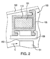
- a blade tip clearance system 100 is located outboard of the radially outward tip 153.
- An external case 103 surrounds blade tip clearance system 100.
- Blade tip clearance system 100 includes a control ring carrier 105 and a control ring 101 defined within carrier 105.
- Control ring 101 defines a centerline axis, e.g. engine central longitudinal axis A.
- An outer air seal 109 is operatively connected to carrier 105 radially inward from control ring 101 and carrier 105.
- control ring 101 includes control ring segments 107 joined together to form a full control ring 101. While only two segments are shown, those skilled in the art will readily appreciate that control ring 101 can be made from any number of suitable segments 107.
- Control ring 101 is held in control ring carrier 105 for thermal isolation from outer air seal 109.
- Each control ring segment 107 includes an inner diameter surface 111 and an outer diameter surface 113. Inner and outer diameter surfaces, 111 and 113, respectively, include thermally isolating contacts 115. Thermally isolating contacts 115 have lower thermal conductivity than the control ring, thereby increasing the thermal isolation.
- thermally isolating contacts 115 can also be on only one of inner and outer diameter surfaces, 111 and 113, respectively, instead of both, or can vary throughout control ring 101.
- each control ring segment 107 includes respective cavities 117 defined in inner and outer diameter surfaces, 111 and 113, respectively, with wedge shaped thermally isolating inlays 119 defined therein.
- Thermally isolating inlays 119 can be made from ceramic.
- Thermally isolating inlays 119 extend to their respective inner and outer diameter surfaces, 111 and 113, respectively, and define thermally isolating contacts 115.
- Thermally isolating contacts 115, inlays 119, and cavities 117 are circumferentially spaced apart from other isolating contacts 115, inlays 119, and cavities 117, along their respective inner or outer diameter surfaces, 111 and 113, respectively.
- thermally isolating contacts 115, inlays 119, and cavities 117 can also be on only one of inner and outer diameter surfaces, 111 and 113, respectively, instead of both, or can vary throughout control ring 101. It is also contemplated that instead of, or in addition to, thermally isolating contacts 115 on inner and outer diameter surfaces, 111 and 113, respectively, thermally isolating contacts 115 can also be disposed on an inner diameter surface of carrier 105, e.g. the surface of carrier 105 that interfaces with outer diameter surface 113 of control ring 101.
- thermally isolating inlays 119 can have a variety of shapes and orientations, for example, thermally isolating inlays 115 can be axially extending cylinders, radially extending cylinders, or blocks. Those skilled in the art will readily appreciate that during manufacture, inlays 119 are placed into cavities 117 and extend radially outward from their respective inner and outer diameter surfaces, 111 and 113. After placement, inlays 119 can be machined down to their respective inner and outer diameter surfaces, 111 and 113.
- control ring 201 is similar to control ring 101.
- Control ring 201 includes thermally isolating contacts 215 that are thermally isolating coatings 217 disposed on respective inner and outer diameter surfaces, 211 and 213, of control ring 201 instead of inlays, e.g. inlays 117.
- Control ring 201 also includes thermally isolating contacts 215 that are separate thermally isolating rings 209 operatively connected to respective inner and outer diameter surfaces, 211 and 213, respectively. It is contemplated that thermally isolating inlays, similar to inlays 119 of control ring 101, can also be incorporated into the segments 207 of control ring 201 and can be made from a ceramic material.
- thermally isolating contacts 215 can also be disposed on an inner diameter surface of a carrier, e.g. carrier 105.
- thermally isolating coatings 217 can also be on only one of inner and outer diameter surfaces, 211 and 213, respectively, instead of both, or can vary throughout control ring 201. It is contemplated that thermally isolating rings 209 can be on only one of inner and outer diameter surfaces, 211 and 213, respectively, can be separated into discrete arcuate segments, and/or can be a full hoop.
- control ring 301 is similar to control rings 101 and 201.
- Each segment 307 of control ring 301 includes an internal cavity 317 defined between inner and outer diameter surfaces, 311 and 313, respectively.
- Internal cavity 317 includes a fill material 319 having a higher heat capacitance than control ring 301.
- Control ring 301 includes a plug 321 to enclose internal cavity 317.
- Plug 321 can be welded or brazed between internal cavity 317 and outer diameter surface 313. It is contemplated that cavity 317 can be formed through casting, direct metal laser sintering (DMLS), or can be a welded ring assembly. It is contemplated that fill material 319 can be a fluid sealed inside the internal cavity.
- DMLS direct metal laser sintering
- fill materials can be used, for example, a material with a higher heat capacity than control ring 301, such as, water, liquid ammonia, cement and/or lithium.
- a material with a higher heat capacity than control ring 301 such as, water, liquid ammonia, cement and/or lithium.
- control ring 401 includes a plurality of radially stacked rings 409, e.g. multiple plies of material, to achieve a desired thermal response rate.
- Each radially stacked ring 409 includes a plurality of arcuate segments 407 joined together to form ring 401.
- Radially stacked rings 409 each include holes 419 in order to be joined together using pins 421.
- Radially stacked rings 409 are made from a different material from another one of rings 409, e.g. ring 409a is a different material than ring 409b. Seams 411 are defined between the respective segments 407 of radially stacked rings 409.
- Respective seams 411 of one of the radially stacked rings are circumferentially offset from the respective seams 411 of the adjacent radially stacked ring 409.
- control ring 401 is described as having multiple plies of different materials, each radially stacked ring 409 can be made from a single material.
Landscapes
- Engineering & Computer Science (AREA)
- General Engineering & Computer Science (AREA)
- Mechanical Engineering (AREA)
- Turbine Rotor Nozzle Sealing (AREA)
Abstract
Description
- The present disclosure relates to blade tip clearance systems for use in gas turbine engines, and more particularly to control rings for blade tip clearance systems.
- Leakage of flow-path air may occur in turbomachinery between the tips of a rotating blade structure and the outer static structure. This leakage has a negative effect on performance, efficiency, fuel burn, and component life. Turbomachinery with a wide operating range, such as an aircraft gas turbine engine, conventionally requires large tip clearances due to the mismatch in thermal responses between the rotating structure and the static structure. A static structure with a rapid thermal response rate will experience significant closure to the rotating structure during rapid decelerations. Conversely, a static structure with a slow thermal response will experience significant closure to the rotating structure during rapid accelerations. Further, the rotating blade structure generally includes two rotating structures, the blade airfoils that generally have fast thermal response rates and the rotor disk, that generally responds slower.
- As a result, both configurations require large tip clearances throughout the operating range. Large tip clearance can equate to lower efficiency. By minimizing the tip clearance between the rotating and static structures efficiency can be improved. In some designs, an annular control ring is provided on the outer static structure to control the thermal response of the blade outer air seal system, at least under some operational conditions.
- Such conventional methods and systems have generally been considered satisfactory for their intended purpose. However, there is still a need in the art for an improved sealing system. The present disclosure provides a solution for this need.
- A control ring for use in a gas turbine engine includes a control ring segment defining a centerline axis. The control ring segment includes an inner diameter surface and an outer diameter surface. A thermally isolating contact is operatively connected to at least one of the inner diameter surface and the outer diameter surface. The thermally isolating contact has lower thermal conductivity than the control ring.
- The control ring segment can be one of a plurality of control ring segments joined together to form a full control ring configured to be held in a control ring carrier for thermal isolation from an outer air seal.
- In a further embodiment of any of the foregoing embodiments, the thermally isolating contact may additionally and/or alternatively be one of a plurality of thermally isolating contacts on the outer diameter surface of the control ring segment. Further, the thermally isolating contacts can be circumferentially spaced apart from one another.
- In a further embodiment of any of the foregoing embodiments, the thermally isolating contact may additionally and/or alternatively be one of a plurality of thermally isolating contacts on the inner diameter surface of the control ring segment. Further, the thermally isolating contacts may be circumferentially spaced apart from one another.
- In a further embodiment of any of the foregoing embodiments, the thermally isolating contact may additionally and/or alternatively be a coating disposed on at least one of the inner diameter surface or the outer diameter surface of the control ring.
- In a further embodiment of any of the foregoing embodiments, the control ring segment may additionally and/or alternatively include a cavity on the outer diameter surface with a thermally isolating inlay defined therein. Further, the thermally isolating inlay can extend to the outer diameter surface and can define the thermally isolating contact.
- In a further embodiment of any of the foregoing embodiments, the control ring segment may additionally and/or alternatively include a cavity on the inner diameter surface with a thermally isolating inlay defined therein. Further, the thermally isolating inlay can extend to the inner diameter surface and can define the thermally isolating contact.
- In a further embodiment of any of the foregoing embodiments, the thermally isolating inlay may additionally and/or alternatively be at least one of an axially extending cylinder, a radially extending cylinder, or a wedge shape.
- In a further embodiment of any of the foregoing embodiments, the cavity may additionally and/or alternatively be one of a plurality of cavities in the control ring segment. Further, the cavities can be circumferentially spaced apart from one another.
- In another aspect, a control ring for use in a gas turbine engine includes a control ring segment defining a centerline axis. The control ring segment includes an internal cavity defined between the inner and outer diameter surfaces. The internal cavity is configured to contain a material having a higher heat capacitance than the control ring.
- In a further embodiment of any of the foregoing embodiments, the control ring segment may additionally and/or alternatively include a plug between the internal cavity and the outer diameter surface to enclose the internal cavity.
- In a further embodiment of any of the foregoing embodiments, the plug may additionally and/or alternatively be brazed into the outer diameter surface of the control ring segment.
- In a further embodiment of any of the foregoing embodiments, the control ring segment may additionally and/or alternatively be one of a plurality of control ring segments joined together to form a full control ring configured to be held in a control ring carrier for thermal isolation from an outer air seal.
- In a further embodiment of any of the foregoing embodiments, the control ring may additionally and/or alternatively include a fill material having a higher heat capacitance than the control ring disposed within the internal cavity.
- In a further embodiment of any of the foregoing embodiments, the fill material may additionally and/or alternatively be a fluid sealed inside the internal cavity.
- In yet another aspect, a control ring for use in a gas turbine engine includes a plurality of radially stacked rings. Each radially stacked ring includes a plurality of arcuate segments joined together to form the ring.
- In a further embodiment of any of the foregoing embodiments, at least one of the rings may additionally and/or alternatively be made from a different material from another one of the rings.
- In a further embodiment of any of the foregoing embodiments, seams may additionally and/or alternatively be defined between the respective segments of the radially stacked rings. Further, the respective seams of one of the radially stacked rings can be circumferentially offset from the respective seams of the adjacent radially stacked ring.
- According to one embodiment, there is provided a control ring for use in a gas turbine engine, the control ring comprising: a control ring segment defining a centerline axis, wherein the control ring segment includes an inner diameter surface and an outer diameter surface; and a thermally isolating contact operatively connected to at least one of the inner diameter surface and the outer diameter surface, wherein the thermally isolating contact has lower thermal conductivity than the control ring.
- In addition to one or more of the features described above, or as an alternative to any of the foregoing embodiments, the control ring segment is one of a plurality of control ring segments joined together to form a full control ring configured to be held in a control ring carrier for thermal isolation from an outer air seal.
- In addition to one or more of the features described above, or as an alternative to any of the foregoing embodiments, the thermally isolating contact is one of a plurality of thermally isolating contacts on the outer diameter surface of the control ring segment, wherein the thermally isolating contacts are circumferentially spaced apart from one another.
- In addition to one or more of the features described above, or as an alternative to any of the foregoing embodiments, the thermally isolating contact is one of a plurality of thermally isolating contacts on the inner diameter surface of the control ring segment, wherein the thermally isolating contacts are circumferentially spaced apart from one another.
- In addition to one or more of the features described above, or as an alternative to any of the foregoing embodiments, the thermally isolating contact is a coating disposed on at least one of the inner diameter surface or the outer diameter surface of the control ring.
- In addition to one or more of the features described above, or as an alternative to any of the foregoing embodiments, the control ring segment includes a cavity on the outer diameter surface with a thermally isolating inlay defined therein, wherein the thermally isolating inlay extends to the outer diameter surface and defines the thermally isolating contact.
- In addition to one or more of the features described above, or as an alternative to any of the foregoing embodiments, the thermally isolating inlay is at least one of an axially extending cylinder, a radially extending cylinder, or a wedge shape.
- In addition to one or more of the features described above, or as an alternative to any of the foregoing embodiments, the cavity is one of a plurality of cavities in the control ring segment, wherein the cavities are circumferentially spaced apart from one another.
- In addition to one or more of the features described above, or as an alternative to any of the foregoing embodiments, the control ring segment includes a cavity on the inner diameter surface with a thermally isolating inlay defined therein, wherein the thermally isolating inlay extends to the inner diameter surface and defines the thermally isolating contact.
- In addition to one or more of the features described above, or as an alternative to any of the foregoing embodiments, the thermally isolating inlay is at least one of an axially extending cylinder, a radially extending cylinder, or a wedge shape.
- In addition to one or more of the features described above, or as an alternative to any of the foregoing embodiments, the cavity is one of a plurality of cavities in the control ring segment, wherein the cavities are circumferentially spaced apart from one another.
- According to another embodiment, there is provided a control ring for use in a gas turbine engine, the control ring comprising: a control ring segment defining a centerline axis, wherein the control ring segment includes: an inner diameter surface and an outer diameter surface; and an internal cavity defined between the inner and outer diameter surfaces, wherein the internal cavity is configured to contain a material having a higher heat capacitance than the control ring.
- In addition to one or more of the features described above, or as an alternative to any of the foregoing embodiments, the control ring segment includes a plug between the internal cavity and the outer diameter surface to enclose the internal cavity.
- In addition to one or more of the features described above, or as an alternative to any of the foregoing embodiments, the plug is brazed into the outer diameter surface of the control ring segment.
- In addition to one or more of the features described above, or as an alternative to any of the foregoing embodiments, the control ring segment is one of a plurality of control ring segments joined together to form a full control ring configured to be held in a control ring carrier for thermal isolation from an outer air seal.
- In addition to one or more of the features described above, or as an alternative to any of the foregoing embodiments, a fill material having a higher heat capacitance than the control ring disposed within the internal cavity.
- In addition to one or more of the features described above, or as an alternative to any of the foregoing embodiments, the fill material is a fluid sealed inside the internal cavity.
- According to another embodiment, there is provided a control ring for use in a gas turbine engine, the control ring comprising: a plurality of radially stacked rings, wherein each radially stacked ring includes a plurality of arcuate segments joined together to form the ring.
- In addition to one or more of the features described above, or as an alternative to any of the foregoing embodiments, at least one of the rings is made from a different material from another one of the rings.
- In addition to one or more of the features described above, or as an alternative to any of the foregoing embodiments, seams are defined between the respective segments of the radially stacked rings, wherein the respective seams of one of the radially stacked rings are circumferentially offset from the respective seams of the adjacent radially stacked ring.
- These and other features of the systems and methods of the subject disclosure will become more readily apparent to those skilled in the art from the following detailed description of the preferred embodiments taken in conjunction with the drawings.
- So that those skilled in the art to which the subject disclosure appertains will readily understand how to make and use the devices and methods of the subject disclosure without undue experimentation, preferred embodiments thereof will be described in detail herein below with reference to certain figures, wherein:
-
Fig. 1 is a schematic cross-sectional side elevation view of an exemplary embodiment of a gas turbine engine constructed in accordance with the present disclosure, showing the location of the blades; -
Fig. 2 is a schematic cross-sectional side elevation view of a blade tip clearance system constructed in accordance with embodiments of the present disclosure, showing the control ring and the carrier; -
Fig. 3A is a perspective view of a portion of the control ring ofFig. 2 , showing the control ring having wedge shaped thermally isolating inlays; -
Fig. 3B is a perspective view of a portion of the control ring ofFig. 2 , showing the control ring having cylindrical and block shaped thermally isolating inlays; -
Fig. 4 is a perspective view of a portion of another embodiment of a control ring constructed in accordance with embodiments of the present disclosure, showing the control ring having thermally isolating coated portions; -
Fig. 5 is a cross-sectional side elevation view of another embodiment of a control ring constructed in accordance with embodiments of the present disclosure, showing the control ring having an internal cavity filled with a material having a higher heat capacitance than the control ring; and -
Fig. 6 is an exploded perspective view of a portion of another embodiment of a control ring constructed in accordance with embodiments of the present disclosure, showing the control ring having multiple plies of material. - Reference will now be made to the drawings wherein like reference numerals identify similar structural features or aspects of the subject disclosure. For purposes of explanation and illustration, and not limitation, a cross-sectional side elevation view of an exemplary embodiment of a gas turbine engine accordance with the disclosure is shown in
Fig. 1 and is designated generally byreference character 20. Other embodiments of gas turbine engines in accordance with the disclosure, or aspects thereof, are provided inFigs. 2-6 , as will be described. The systems and methods described herein can be used to provide improved tip clearance control between the rotating blade tip and static blade outer air seal at various operating conditions experienced in gas turbine engines. -
Fig. 1 schematically illustrates agas turbine engine 20. Thegas turbine engine 20 is disclosed herein as a two-spool turbofan that generally incorporates afan section 22, acompressor section 24, acombustor section 26 and aturbine section 28. Alternative engines might include an augmentor section (not shown) among other systems or features. Thefan section 22 drives air along a bypass flow path B in a bypass duct defined within anacelle 15, while thecompressor section 24 drives air along a core flow path C for compression and communication into thecombustor section 26 then expansion through theturbine section 28. Although depicted as a two-spool turbofan gas turbine engine in the disclosed non-limiting embodiment, it should be understood that the concepts described herein are not limited to use with two-spool turbofans as the teachings may be applied to other types of turbine engines including three-spool architectures. - The
exemplary engine 20 generally includes alow speed spool 30 and ahigh speed spool 32 mounted for rotation about an engine central longitudinal axis A relative to an enginestatic structure 36 viaseveral bearing systems 38. It should be understood that various bearingsystems 38 at various locations may alternatively or additionally be provided, and the location of bearingsystems 38 may be varied as appropriate to the application. - The
low speed spool 30 generally includes aninner shaft 40 that interconnects afan 42, alow pressure compressor 44 and alow pressure turbine 46. Theinner shaft 40 is connected to thefan 42 through a speed change mechanism, which in exemplarygas turbine engine 20 is illustrated as a gearedarchitecture 48 to drive thefan 42 at a lower speed than thelow speed spool 30. Thehigh speed spool 32 includes anouter shaft 50 that interconnects ahigh pressure compressor 52 andhigh pressure turbine 54. Acombustor 56 is arranged inexemplary gas turbine 20 between thehigh pressure compressor 52 and thehigh pressure turbine 54. A mid-turbine frame 58 of the enginestatic structure 36 is arranged generally between thehigh pressure turbine 54 and thelow pressure turbine 46. The mid-turbine frame 58 furthersupports bearing systems 38 in theturbine section 28. Theinner shaft 40 and theouter shaft 50 are concentric and rotate via bearingsystems 38 about the engine central longitudinal axis A which is collinear with their longitudinal axes. - The core airflow is compressed by the
low pressure compressor 44 then thehigh pressure compressor 52, mixed and burned with fuel in thecombustor 56, then expanded over thehigh pressure turbine 54 andlow pressure turbine 46. The mid-turbine frame 58 includesairfoils 59 that are in the core airflow path C. Theturbines low speed spool 30 andhigh speed spool 32 in response to the expansion. It will be appreciated that each of the positions of thefan section 22,compressor section 24,combustor section 26,turbine section 28, and fandrive gear system 48 may be varied. For example,gear system 48 may be located aft ofcombustor section 26 or even aft ofturbine section 28, andfan section 22 may be positioned forward or aft of the location ofgear system 48. - The
engine 20 in one example is a high-bypass geared aircraft engine. In a further example, theengine 20 bypass ratio is greater than about six (6), with an example embodiment being greater than about ten (10), the gearedarchitecture 48 is an epicyclic gear train, such as a planetary gear system or other gear system, with a gear reduction ratio of greater than about 2.3 and thelow pressure turbine 46 has a pressure ratio that is greater than about five (5:1). In one disclosed embodiment, theengine 20 bypass ratio is greater than about ten (10:1), the fan diameter is significantly larger than that of thelow pressure compressor 44, and thelow pressure turbine 46 has a pressure ratio that is greater than about five (5:1).Low pressure turbine 46 pressure ratio is pressure measured prior to inlet oflow pressure turbine 46 as related to the pressure at the outlet of thelow pressure turbine 46 prior to an exhaust nozzle. The gearedarchitecture 48 may be an epicycle gear train, such as a planetary gear system or other gear system, with a gear reduction ratio of greater than about 2.3:1. It should be understood, however, that the above parameters are only exemplary of one embodiment of a geared architecture engine and that embodiments of the present invention are applicable to other gas turbine engines including direct drive turbofans. - A significant amount of thrust is provided by the bypass flow B due to the high bypass ratio. The
fan section 22 of theengine 20 is designed for a particular flight condition -- typically cruise at about 0.8 Mach and about 35,000 feet. The flight condition of 0.8 Mach and 35,000 ft, with the engine at its best fuel consumption - also known as "bucket cruise Thrust Specific Fuel Consumption ('TSFC')" - is the industry standard parameter of lbm of fuel being burned divided by lbf of thrust the engine produces at that minimum point. "Low fan pressure ratio" is the pressure ratio across the fan blade alone, without a Fan Exit Guide Vane ("FEGV") system. The low fan pressure ratio as disclosed herein according to one non-limiting embodiment is less than about 1.45. "Low corrected fan tip speed" is the actual fan tip speed in ft/sec divided by an industry standard temperature correction of [(Tram °R) / (518.7 °R)]0.5. The "Low corrected fan tip speed" as disclosed herein according to one non-limiting embodiment is less than about 1150 ft / second. - As shown in
Figs. 1 and2 ,gas turbine engine 20 includes rotating structures, e.g. high and low speed spools 32 and 30, with a plurality ofrotating blades Fig. 2 , each of the plurality ofrotating blades 151 includes a radiallyoutward tip 153. A bladetip clearance system 100 is located outboard of the radiallyoutward tip 153. Anexternal case 103 surrounds bladetip clearance system 100. Bladetip clearance system 100 includes acontrol ring carrier 105 and acontrol ring 101 defined withincarrier 105.Control ring 101 defines a centerline axis, e.g. engine central longitudinal axis A. Anouter air seal 109 is operatively connected tocarrier 105 radially inward fromcontrol ring 101 andcarrier 105. - With reference now to
Figs. 2-3B ,control ring 101 includescontrol ring segments 107 joined together to form afull control ring 101. While only two segments are shown, those skilled in the art will readily appreciate thatcontrol ring 101 can be made from any number ofsuitable segments 107.Control ring 101 is held incontrol ring carrier 105 for thermal isolation fromouter air seal 109. Eachcontrol ring segment 107 includes aninner diameter surface 111 and anouter diameter surface 113. Inner and outer diameter surfaces, 111 and 113, respectively, include thermally isolatingcontacts 115. Thermally isolatingcontacts 115 have lower thermal conductivity than the control ring, thereby increasing the thermal isolation. While shown on both inner and outer diameter surfaces, 111 and 113, respectively, those skilled in the art will readily appreciate that thermally isolatingcontacts 115, can also be on only one of inner and outer diameter surfaces, 111 and 113, respectively, instead of both, or can vary throughoutcontrol ring 101. - As shown in
Fig. 3A , eachcontrol ring segment 107 includesrespective cavities 117 defined in inner and outer diameter surfaces, 111 and 113, respectively, with wedge shaped thermally isolatinginlays 119 defined therein. Thermally isolatinginlays 119, for example, can be made from ceramic. Thermally isolatinginlays 119 extend to their respective inner and outer diameter surfaces, 111 and 113, respectively, and define thermally isolatingcontacts 115. Thermally isolatingcontacts 115, inlays 119, andcavities 117 are circumferentially spaced apart from other isolatingcontacts 115, inlays 119, andcavities 117, along their respective inner or outer diameter surfaces, 111 and 113, respectively. While shown on both inner and outer diameter surfaces, 111 and 113, respectively, those skilled in the art will readily appreciate that thermally isolatingcontacts 115, inlays 119, andcavities 117 can also be on only one of inner and outer diameter surfaces, 111 and 113, respectively, instead of both, or can vary throughoutcontrol ring 101. It is also contemplated that instead of, or in addition to, thermally isolatingcontacts 115 on inner and outer diameter surfaces, 111 and 113, respectively, thermally isolatingcontacts 115 can also be disposed on an inner diameter surface ofcarrier 105, e.g. the surface ofcarrier 105 that interfaces withouter diameter surface 113 ofcontrol ring 101. - As shown in
Fig. 3B , thermally isolatinginlays 119 can have a variety of shapes and orientations, for example, thermally isolatinginlays 115 can be axially extending cylinders, radially extending cylinders, or blocks. Those skilled in the art will readily appreciate that during manufacture, inlays 119 are placed intocavities 117 and extend radially outward from their respective inner and outer diameter surfaces, 111 and 113. After placement, inlays 119 can be machined down to their respective inner and outer diameter surfaces, 111 and 113. - With reference now to
Fig. 4 ,control ring 201 is similar to controlring 101.Control ring 201 includes thermally isolatingcontacts 215 that are thermally isolatingcoatings 217 disposed on respective inner and outer diameter surfaces, 211 and 213, ofcontrol ring 201 instead of inlays, e.g. inlays 117.Control ring 201 also includes thermally isolatingcontacts 215 that are separate thermally isolatingrings 209 operatively connected to respective inner and outer diameter surfaces, 211 and 213, respectively. It is contemplated that thermally isolating inlays, similar toinlays 119 ofcontrol ring 101, can also be incorporated into thesegments 207 ofcontrol ring 201 and can be made from a ceramic material. It is also contemplated that instead of, or in addition to, thermally isolatingcontacts 215 on inner and outer diameter surfaces, 211 and 213, respectively, thermally isolatingcontacts 215 can also be disposed on an inner diameter surface of a carrier,e.g. carrier 105. - With continued reference to
Fig. 4 , whilecoatings 217 are shown as patches, those skilled in the art will readily appreciate that the entirety ofring 201 can be coated. While shown on both inner and outer diameter surfaces, 211 and 213, respectively, those skilled in the art will readily appreciate that thermally isolatingcoatings 217 can also be on only one of inner and outer diameter surfaces, 211 and 213, respectively, instead of both, or can vary throughoutcontrol ring 201. It is contemplated that thermally isolatingrings 209 can be on only one of inner and outer diameter surfaces, 211 and 213, respectively, can be separated into discrete arcuate segments, and/or can be a full hoop. - As shown in
Fig. 5 ,control ring 301 is similar to controlrings control ring 301 includes aninternal cavity 317 defined between inner and outer diameter surfaces, 311 and 313, respectively.Internal cavity 317 includes afill material 319 having a higher heat capacitance thancontrol ring 301.Control ring 301 includes aplug 321 to encloseinternal cavity 317. Plug 321 can be welded or brazed betweeninternal cavity 317 andouter diameter surface 313. It is contemplated thatcavity 317 can be formed through casting, direct metal laser sintering (DMLS), or can be a welded ring assembly. It is contemplated that fillmaterial 319 can be a fluid sealed inside the internal cavity. Those skilled in the art will readily appreciate that a variety of fill materials can be used, for example, a material with a higher heat capacity thancontrol ring 301, such as, water, liquid ammonia, cement and/or lithium. By fillingcontrol ring 301 with a high heat capacitance material, the thermal response rate ofcontrol ring 301 is reduced, tending to better mirror the properties of a rotor disk. For example, water has a much higher heat capacity than metals, resulting in water taking much longer to heat up than metal. - With reference now to
Fig. 6 ,control ring 401 includes a plurality of radially stackedrings 409, e.g. multiple plies of material, to achieve a desired thermal response rate. Each radially stackedring 409 includes a plurality ofarcuate segments 407 joined together to formring 401. Radially stackedrings 409 each includeholes 419 in order to be joined together using pins 421. Radially stackedrings 409 are made from a different material from another one ofrings 409, e.g. ring 409a is a different material thanring 409b.Seams 411 are defined between therespective segments 407 of radially stacked rings 409.Respective seams 411 of one of the radially stacked rings, e.g. radially stackedring 409a, are circumferentially offset from therespective seams 411 of the adjacent radially stackedring 409. Those skilled in the art will readily appreciate that whilecontrol ring 401 is described as having multiple plies of different materials, each radially stackedring 409 can be made from a single material. - The methods and systems as described above and shown in the drawings, can provide for control rings with superior properties including increased control over thermal properties, such as, conductivity, heat capacitance and thermal response. While the apparatus and methods of the subject disclosure have been shown and described with reference to preferred embodiments, those skilled in the art will readily appreciate that changes and/or modifications may be made thereto without departing from the scope of the subject disclosure.
- The following clauses set out features of the invention which may or may not presently be claimed in this application but which may form basis for future amendment or a divisional application.
- 1. A control ring for use in a gas turbine engine, the control ring comprising:
- a control ring segment defining a centerline axis, wherein the control ring segment includes an inner diameter surface and an outer diameter surface; and
- a thermally isolating contact operatively connected to at least one of the inner diameter surface and the outer diameter surface, wherein the thermally isolating contact has lower thermal conductivity than the control ring.
- 2. A control ring as recited in clause 1, wherein the control ring segment is one of a plurality of control ring segments joined together to form a full control ring configured to be held in a control ring carrier for thermal isolation from an outer air seal.
- 3. A control ring as recited in clause 1, wherein the thermally isolating contact is one of a plurality of thermally isolating contacts on the outer diameter surface of the control ring segment, wherein the thermally isolating contacts are circumferentially spaced apart from one another.
- 4. A control ring as recited in clause 1, wherein the thermally isolating contact is one of a plurality of thermally isolating contacts on the inner diameter surface of the control ring segment, wherein the thermally isolating contacts are circumferentially spaced apart from one another.
- 5. A control ring as recited in clause 1, wherein the thermally isolating contact is a coating disposed on at least one of the inner diameter surface or the outer diameter surface of the control ring.
- 6. A control ring as recited in clause 1, wherein the control ring segment includes a cavity on the outer diameter surface with a thermally isolating inlay defined therein, wherein the thermally isolating inlay extends to the outer diameter surface and defines the thermally isolating contact.
- 7. A control ring as recited in clause 6, wherein the thermally isolating inlay is at least one of an axially extending cylinder, a radially extending cylinder, or a wedge shape.
- 8. A control ring as recited in clause 6, wherein the cavity is one of a plurality of cavities in the control ring segment, wherein the cavities are circumferentially spaced apart from one another.
- 9. A control ring as recited in clause 1, wherein the control ring segment includes a cavity on the inner diameter surface with a thermally isolating inlay defined therein, wherein the thermally isolating inlay extends to the inner diameter surface and defines the thermally isolating contact.
- 10. A control ring as recited in clause 9, wherein the thermally isolating inlay is at least one of an axially extending cylinder, a radially extending cylinder, or a wedge shape.
- 11. A control ring as recited in clause 9, wherein the cavity is one of a plurality of cavities in the control ring segment, wherein the cavities are circumferentially spaced apart from one another.
- 12. A control ring for use in a gas turbine engine, the control ring comprising:
- a control ring segment defining a centerline axis, wherein the control ring segment includes:
- an inner diameter surface and an outer diameter surface; and
- an internal cavity defined between the inner and outer diameter surfaces, wherein the internal cavity is configured to contain a material having a higher heat capacitance than the control ring.
- a control ring segment defining a centerline axis, wherein the control ring segment includes:
- 13. A control ring as recited in clause 12, wherein the control ring segment includes a plug between the internal cavity and the outer diameter surface to enclose the internal cavity.
- 14. A control ring as recited in clause 13, wherein the plug is brazed into the outer diameter surface of the control ring segment.
- 15. A control ring as recited in clause 12, wherein the control ring segment is one of a plurality of control ring segments joined together to form a full control ring configured to be held in a control ring carrier for thermal isolation from an outer air seal.
- 16. A control ring as recited in clause 12, further comprising a fill material having a higher heat capacitance than the control ring disposed within the internal cavity.
- 17. A control ring as recited in clause 16, wherein the fill material is a fluid sealed inside the internal cavity.
- 18. A control ring for use in a gas turbine engine, the control ring comprising:
- a plurality of radially stacked rings, wherein each radially stacked ring includes a plurality of arcuate segments joined together to form the ring.
- 19. A control ring as recited in clause 18, wherein at least one of the rings is made from a different material from another one of the rings.
- 20. A control ring as recited in clause 18, wherein seams are defined between the respective segments of the radially stacked rings, wherein the respective seams of one of the radially stacked rings are circumferentially offset from the respective seams of the adjacent radially stacked ring.
Claims (15)
- A control ring (101) for use in a gas turbine engine (20), the control ring comprising:a control ring segment (107) defining a centerline axis, wherein the control ring segment includes an inner diameter surface (111) and an outer diameter surface (113); anda thermally isolating contact (115) operatively connected to at least one of the inner diameter surface and the outer diameter surface, wherein the thermally isolating contact has lower thermal conductivity than the control ring.
- A control ring as recited in claim 1, wherein the control ring segment is one of a plurality of control ring segments joined together to form a full control ring configured to be held in a control ring carrier (105) for thermal isolation from an outer air seal (109).
- A control ring as recited in claim 1 or 2, wherein the thermally isolating contact is one of a plurality of thermally isolating contacts on the outer diameter surface of the control ring segment, wherein the thermally isolating contacts are circumferentially spaced apart from one another and/or wherein the thermally isolating contact is one of a plurality of thermally isolating contacts on the inner diameter surface of the control ring segment, wherein the thermally isolating contacts are circumferentially spaced apart from one another.
- A control ring as recited in claim 1 or 2, wherein the thermally isolating contact is a coating (217) disposed on at least one of the inner diameter surface or the outer diameter surface of the control ring.
- A control ring as recited in claim 1, 2 or 3, wherein the control ring segment includes a cavity (117) on the outer diameter surface with a thermally isolating inlay (119) defined therein, wherein the thermally isolating inlay extends to the outer diameter surface and defines the thermally isolating contact, and/or wherein the control ring segment includes a cavity on the inner diameter surface with a thermally isolating inlay defined therein, wherein the thermally isolating inlay extends to the inner diameter surface and defines the thermally isolating contact.
- A control ring as recited in claim 5, wherein the thermally isolating inlay is at least one of an axially extending cylinder, a radially extending cylinder, or a wedge shape.
- A control ring as recited in claim 5 or 6, wherein the cavity is one of a plurality of cavities in the control ring segment, wherein the cavities are circumferentially spaced apart from one another.
- A control ring (301) for use in a gas turbine engine (20), the control ring comprising:a control ring segment (307) defining a centerline axis, wherein the control ring segment includes:an inner diameter surface (311) and an outer diameter surface (313); andan internal cavity (317) defined between the inner and outer diameter surfaces, wherein the internal cavity is configured to contain a material (319) having a higher heat capacitance than the control ring.
- A control ring as recited in claim 8, wherein the control ring segment includes a plug (321) between the internal cavity and the outer diameter surface to enclose the internal cavity.
- A control ring as recited in claim 9, wherein the plug is brazed into the outer diameter surface of the control ring segment.
- A control ring as recited in claim 8, 9 or 10, wherein the control ring segment is one of a plurality of control ring segments joined together to form a full control ring configured to be held in a control ring carrier (105) for thermal isolation from an outer air seal (109).
- A control ring as recited in any of claims 8 to 11, further comprising a fill material having a higher heat capacitance than the control ring disposed within the internal cavity, preferably wherein the fill material is a fluid sealed inside the internal cavity.
- A control ring (401) for use in a gas turbine engine (20), the control ring comprising:a plurality of radially stacked rings (409), wherein each radially stacked ring includes a plurality of arcuate segments (407) joined together to form the ring.
- A control ring as recited in claim 13, wherein at least one of the rings is made from a different material from another one of the rings.
- A control ring as recited in claim 13 or 14, wherein seams (411) are defined between the respective segments of the radially stacked rings, wherein the respective seams of one of the radially stacked rings are circumferentially offset from the respective seams of the adjacent radially stacked ring.
Priority Applications (1)
| Application Number | Priority Date | Filing Date | Title |
|---|---|---|---|
| EP19216678.3A EP3650658B1 (en) | 2015-05-06 | 2016-02-29 | Control ring |
Applications Claiming Priority (1)
| Application Number | Priority Date | Filing Date | Title |
|---|---|---|---|
| US14/705,273 US10612408B2 (en) | 2015-05-06 | 2015-05-06 | Control rings |
Related Child Applications (2)
| Application Number | Title | Priority Date | Filing Date |
|---|---|---|---|
| EP19216678.3A Division EP3650658B1 (en) | 2015-05-06 | 2016-02-29 | Control ring |
| EP19216678.3A Division-Into EP3650658B1 (en) | 2015-05-06 | 2016-02-29 | Control ring |
Publications (3)
| Publication Number | Publication Date |
|---|---|
| EP3121388A2 true EP3121388A2 (en) | 2017-01-25 |
| EP3121388A3 EP3121388A3 (en) | 2017-04-19 |
| EP3121388B1 EP3121388B1 (en) | 2022-03-30 |
Family
ID=55446709
Family Applications (2)
| Application Number | Title | Priority Date | Filing Date |
|---|---|---|---|
| EP19216678.3A Active EP3650658B1 (en) | 2015-05-06 | 2016-02-29 | Control ring |
| EP16157952.9A Active EP3121388B1 (en) | 2015-05-06 | 2016-02-29 | Control rings for use in a gas turbine |
Family Applications Before (1)
| Application Number | Title | Priority Date | Filing Date |
|---|---|---|---|
| EP19216678.3A Active EP3650658B1 (en) | 2015-05-06 | 2016-02-29 | Control ring |
Country Status (2)
| Country | Link |
|---|---|
| US (2) | US10612408B2 (en) |
| EP (2) | EP3650658B1 (en) |
Families Citing this family (6)
| Publication number | Priority date | Publication date | Assignee | Title |
|---|---|---|---|---|
| EP3351735B1 (en) | 2017-01-23 | 2023-10-18 | MTU Aero Engines AG | Turbomachine housing element |
| IT201800002027A1 (en) * | 2018-01-26 | 2019-07-26 | Turboden Spa | Fluid seal device for rotating machines |
| FR3086323B1 (en) | 2018-09-24 | 2020-12-11 | Safran Aircraft Engines | INTERNAL TURMOMACHINE HOUSING WITH IMPROVED THERMAL INSULATION |
| CN109372585B (en) * | 2018-12-10 | 2021-08-03 | 中国航发四川燃气涡轮研究院 | Turbine baffle plate with built-in heat preservation pipe |
| US11306604B2 (en) | 2020-04-14 | 2022-04-19 | Raytheon Technologies Corporation | HPC case clearance control thermal control ring spoke system |
| KR102316629B1 (en) | 2020-06-23 | 2021-10-25 | 두산중공업 주식회사 | Turbine blade tip clearance control apparatus and gas turbine comprising the same |
Family Cites Families (15)
| Publication number | Priority date | Publication date | Assignee | Title |
|---|---|---|---|---|
| GB1548836A (en) * | 1977-03-17 | 1979-07-18 | Rolls Royce | Gasturbine engine |
| DE3019920C2 (en) * | 1980-05-24 | 1982-12-30 | MTU Motoren- und Turbinen-Union München GmbH, 8000 München | Device for the outer casing of the rotor blades of axial turbines for gas turbine engines |
| US5192186A (en) * | 1980-10-03 | 1993-03-09 | Rolls-Royce Plc | Gas turbine engine |
| FR2724973B1 (en) * | 1982-12-31 | 1996-12-13 | Snecma | DEVICE FOR SEALING MOBILE BLADES OF A TURBOMACHINE WITH REAL-TIME ACTIVE GAME CONTROL AND METHOD FOR DETERMINING SAID DEVICE |
| GB2257754B (en) * | 1983-02-26 | 1993-09-29 | Rolls Royce | Improvements in or relating to axial flow gas turbines |
| DE3316535A1 (en) * | 1983-05-06 | 1984-11-08 | MTU Motoren- und Turbinen-Union München GmbH, 8000 München | TURBO COMPRESSOR WITH INLET COVER |
| US7247002B2 (en) * | 2004-12-02 | 2007-07-24 | Siemens Power Generation, Inc. | Lamellate CMC structure with interlock to metallic support structure |
| US8303247B2 (en) * | 2007-09-06 | 2012-11-06 | United Technologies Corporation | Blade outer air seal |
| US8342798B2 (en) * | 2009-07-28 | 2013-01-01 | General Electric Company | System and method for clearance control in a rotary machine |
| US8790067B2 (en) | 2011-04-27 | 2014-07-29 | United Technologies Corporation | Blade clearance control using high-CTE and low-CTE ring members |
| US8894359B2 (en) * | 2011-12-08 | 2014-11-25 | Siemens Aktiengesellschaft | Gas turbine engine with outer case ambient external cooling system |
| US9121301B2 (en) | 2012-03-20 | 2015-09-01 | General Electric Company | Thermal isolation apparatus |
| RU2499145C1 (en) * | 2012-05-21 | 2013-11-20 | Николай Борисович Болотин | Turbine of bypass gas turbine engine |
| US9447696B2 (en) | 2012-12-27 | 2016-09-20 | United Technologies Corporation | Blade outer air seal system for controlled tip clearance |
| US9976435B2 (en) * | 2014-12-19 | 2018-05-22 | United Technologies Corporation | Blade tip clearance systems |
-
2015
- 2015-05-06 US US14/705,273 patent/US10612408B2/en active Active
-
2016
- 2016-02-29 EP EP19216678.3A patent/EP3650658B1/en active Active
- 2016-02-29 EP EP16157952.9A patent/EP3121388B1/en active Active
-
2020
- 2020-02-25 US US16/800,257 patent/US20200308976A1/en not_active Abandoned
Non-Patent Citations (1)
| Title |
|---|
| None |
Also Published As
| Publication number | Publication date |
|---|---|
| US10612408B2 (en) | 2020-04-07 |
| EP3650658B1 (en) | 2022-11-23 |
| EP3121388A3 (en) | 2017-04-19 |
| EP3121388B1 (en) | 2022-03-30 |
| US20160326900A1 (en) | 2016-11-10 |
| US20200308976A1 (en) | 2020-10-01 |
| EP3650658A2 (en) | 2020-05-13 |
| EP3650658A3 (en) | 2020-08-19 |
Similar Documents
| Publication | Publication Date | Title |
|---|---|---|
| US20200308976A1 (en) | Control rings | |
| US9976435B2 (en) | Blade tip clearance systems | |
| EP2942488B1 (en) | Blade for a gas turbine engine, gas turbine engine and method of cooling a blade for a gas turbine engine | |
| WO2014138320A1 (en) | Gas turbine engine component having variable width feather seal slot | |
| EP3102810B1 (en) | Gas turbine circumferential axial segmented trough seal | |
| EP2944761B1 (en) | Gas turbine engine component with platform cooling circuit | |
| EP3587740A1 (en) | Gas turbine engine component | |
| EP2961547A2 (en) | Gas turbine engine component manufacturing method and core for making same | |
| EP3080400B1 (en) | Gas turbine engine rotor and corresponding method of cooling | |
| EP3056670A1 (en) | Turbomachine component having cooling channels with angled pedestals | |
| EP3693547B1 (en) | Gas turbine engine blade, gas turbine engine and method of manufacturing a gas turbine engine blade | |
| EP3101236B1 (en) | Trailing edge platform seals | |
| EP3502420B1 (en) | Component for a gas turbine engine and corresponding gas turbine engine | |
| EP3517738B1 (en) | Blade outer air seal for a gas turbine engine | |
| US10746033B2 (en) | Gas turbine engine component | |
| EP3095966A1 (en) | Support assembly for a gas turbine engine | |
| EP3708778B1 (en) | Inserts for slotted integrally bladed rotor | |
| EP3176376B1 (en) | Cooling passages for a gas path component of a gas turbine engine | |
| EP3181828B1 (en) | Blade outer air seal with integrated air shield | |
| EP3663517B1 (en) | Component for a gas turbine engine and corresponding gas turbine engine | |
| EP3401509B1 (en) | Blade outer air seal | |
| EP2961964A2 (en) | Gas turbine engine component paired film cooling holes |
Legal Events
| Date | Code | Title | Description |
|---|---|---|---|
| PUAI | Public reference made under article 153(3) epc to a published international application that has entered the european phase |
Free format text: ORIGINAL CODE: 0009012 |
|
| STAA | Information on the status of an ep patent application or granted ep patent |
Free format text: STATUS: THE APPLICATION HAS BEEN PUBLISHED |
|
| AK | Designated contracting states |
Kind code of ref document: A2 Designated state(s): AL AT BE BG CH CY CZ DE DK EE ES FI FR GB GR HR HU IE IS IT LI LT LU LV MC MK MT NL NO PL PT RO RS SE SI SK SM TR |
|
| AX | Request for extension of the european patent |
Extension state: BA ME |
|
| PUAL | Search report despatched |
Free format text: ORIGINAL CODE: 0009013 |
|
| AK | Designated contracting states |
Kind code of ref document: A3 Designated state(s): AL AT BE BG CH CY CZ DE DK EE ES FI FR GB GR HR HU IE IS IT LI LT LU LV MC MK MT NL NO PL PT RO RS SE SI SK SM TR |
|
| AX | Request for extension of the european patent |
Extension state: BA ME |
|
| RIC1 | Information provided on ipc code assigned before grant |
Ipc: F01D 11/18 20060101AFI20170314BHEP |
|
| STAA | Information on the status of an ep patent application or granted ep patent |
Free format text: STATUS: REQUEST FOR EXAMINATION WAS MADE |
|
| 17P | Request for examination filed |
Effective date: 20171019 |
|
| RBV | Designated contracting states (corrected) |
Designated state(s): AL AT BE BG CH CY CZ DE DK EE ES FI FR GB GR HR HU IE IS IT LI LT LU LV MC MK MT NL NO PL PT RO RS SE SI SK SM TR |
|
| GRAP | Despatch of communication of intention to grant a patent |
Free format text: ORIGINAL CODE: EPIDOSNIGR1 |
|
| STAA | Information on the status of an ep patent application or granted ep patent |
Free format text: STATUS: GRANT OF PATENT IS INTENDED |
|
| INTG | Intention to grant announced |
Effective date: 20190819 |
|
| GRAJ | Information related to disapproval of communication of intention to grant by the applicant or resumption of examination proceedings by the epo deleted |
Free format text: ORIGINAL CODE: EPIDOSDIGR1 |
|
| STAA | Information on the status of an ep patent application or granted ep patent |
Free format text: STATUS: REQUEST FOR EXAMINATION WAS MADE |
|
| STAA | Information on the status of an ep patent application or granted ep patent |
Free format text: STATUS: EXAMINATION IS IN PROGRESS |
|
| 17Q | First examination report despatched |
Effective date: 20191216 |
|
| INTC | Intention to grant announced (deleted) | ||
| RAP1 | Party data changed (applicant data changed or rights of an application transferred) |
Owner name: RAYTHEON TECHNOLOGIES CORPORATION |
|
| GRAP | Despatch of communication of intention to grant a patent |
Free format text: ORIGINAL CODE: EPIDOSNIGR1 |
|
| STAA | Information on the status of an ep patent application or granted ep patent |
Free format text: STATUS: GRANT OF PATENT IS INTENDED |
|
| INTG | Intention to grant announced |
Effective date: 20210924 |
|
| GRAS | Grant fee paid |
Free format text: ORIGINAL CODE: EPIDOSNIGR3 |
|
| GRAA | (expected) grant |
Free format text: ORIGINAL CODE: 0009210 |
|
| STAA | Information on the status of an ep patent application or granted ep patent |
Free format text: STATUS: THE PATENT HAS BEEN GRANTED |
|
| AK | Designated contracting states |
Kind code of ref document: B1 Designated state(s): AL AT BE BG CH CY CZ DE DK EE ES FI FR GB GR HR HU IE IS IT LI LT LU LV MC MK MT NL NO PL PT RO RS SE SI SK SM TR |
|
| REG | Reference to a national code |
Ref country code: GB Ref legal event code: FG4D |
|
| REG | Reference to a national code |
Ref country code: CH Ref legal event code: EP |
|
| REG | Reference to a national code |
Ref country code: DE Ref legal event code: R096 Ref document number: 602016070429 Country of ref document: DE |
|
| REG | Reference to a national code |
Ref country code: AT Ref legal event code: REF Ref document number: 1479372 Country of ref document: AT Kind code of ref document: T Effective date: 20220415 |
|
| REG | Reference to a national code |
Ref country code: IE Ref legal event code: FG4D |
|
| REG | Reference to a national code |
Ref country code: LT Ref legal event code: MG9D |
|
| PG25 | Lapsed in a contracting state [announced via postgrant information from national office to epo] |
Ref country code: SE Free format text: LAPSE BECAUSE OF FAILURE TO SUBMIT A TRANSLATION OF THE DESCRIPTION OR TO PAY THE FEE WITHIN THE PRESCRIBED TIME-LIMIT Effective date: 20220330 Ref country code: RS Free format text: LAPSE BECAUSE OF FAILURE TO SUBMIT A TRANSLATION OF THE DESCRIPTION OR TO PAY THE FEE WITHIN THE PRESCRIBED TIME-LIMIT Effective date: 20220330 Ref country code: NO Free format text: LAPSE BECAUSE OF FAILURE TO SUBMIT A TRANSLATION OF THE DESCRIPTION OR TO PAY THE FEE WITHIN THE PRESCRIBED TIME-LIMIT Effective date: 20220630 Ref country code: LT Free format text: LAPSE BECAUSE OF FAILURE TO SUBMIT A TRANSLATION OF THE DESCRIPTION OR TO PAY THE FEE WITHIN THE PRESCRIBED TIME-LIMIT Effective date: 20220330 Ref country code: HR Free format text: LAPSE BECAUSE OF FAILURE TO SUBMIT A TRANSLATION OF THE DESCRIPTION OR TO PAY THE FEE WITHIN THE PRESCRIBED TIME-LIMIT Effective date: 20220330 Ref country code: BG Free format text: LAPSE BECAUSE OF FAILURE TO SUBMIT A TRANSLATION OF THE DESCRIPTION OR TO PAY THE FEE WITHIN THE PRESCRIBED TIME-LIMIT Effective date: 20220630 |
|
| REG | Reference to a national code |
Ref country code: NL Ref legal event code: MP Effective date: 20220330 |
|
| REG | Reference to a national code |
Ref country code: AT Ref legal event code: MK05 Ref document number: 1479372 Country of ref document: AT Kind code of ref document: T Effective date: 20220330 |
|
| PG25 | Lapsed in a contracting state [announced via postgrant information from national office to epo] |
Ref country code: LV Free format text: LAPSE BECAUSE OF FAILURE TO SUBMIT A TRANSLATION OF THE DESCRIPTION OR TO PAY THE FEE WITHIN THE PRESCRIBED TIME-LIMIT Effective date: 20220330 Ref country code: GR Free format text: LAPSE BECAUSE OF FAILURE TO SUBMIT A TRANSLATION OF THE DESCRIPTION OR TO PAY THE FEE WITHIN THE PRESCRIBED TIME-LIMIT Effective date: 20220701 Ref country code: FI Free format text: LAPSE BECAUSE OF FAILURE TO SUBMIT A TRANSLATION OF THE DESCRIPTION OR TO PAY THE FEE WITHIN THE PRESCRIBED TIME-LIMIT Effective date: 20220330 |
|
| PG25 | Lapsed in a contracting state [announced via postgrant information from national office to epo] |
Ref country code: NL Free format text: LAPSE BECAUSE OF FAILURE TO SUBMIT A TRANSLATION OF THE DESCRIPTION OR TO PAY THE FEE WITHIN THE PRESCRIBED TIME-LIMIT Effective date: 20220330 |
|
| PG25 | Lapsed in a contracting state [announced via postgrant information from national office to epo] |
Ref country code: SM Free format text: LAPSE BECAUSE OF FAILURE TO SUBMIT A TRANSLATION OF THE DESCRIPTION OR TO PAY THE FEE WITHIN THE PRESCRIBED TIME-LIMIT Effective date: 20220330 Ref country code: SK Free format text: LAPSE BECAUSE OF FAILURE TO SUBMIT A TRANSLATION OF THE DESCRIPTION OR TO PAY THE FEE WITHIN THE PRESCRIBED TIME-LIMIT Effective date: 20220330 Ref country code: RO Free format text: LAPSE BECAUSE OF FAILURE TO SUBMIT A TRANSLATION OF THE DESCRIPTION OR TO PAY THE FEE WITHIN THE PRESCRIBED TIME-LIMIT Effective date: 20220330 Ref country code: PT Free format text: LAPSE BECAUSE OF FAILURE TO SUBMIT A TRANSLATION OF THE DESCRIPTION OR TO PAY THE FEE WITHIN THE PRESCRIBED TIME-LIMIT Effective date: 20220801 Ref country code: ES Free format text: LAPSE BECAUSE OF FAILURE TO SUBMIT A TRANSLATION OF THE DESCRIPTION OR TO PAY THE FEE WITHIN THE PRESCRIBED TIME-LIMIT Effective date: 20220330 Ref country code: EE Free format text: LAPSE BECAUSE OF FAILURE TO SUBMIT A TRANSLATION OF THE DESCRIPTION OR TO PAY THE FEE WITHIN THE PRESCRIBED TIME-LIMIT Effective date: 20220330 Ref country code: CZ Free format text: LAPSE BECAUSE OF FAILURE TO SUBMIT A TRANSLATION OF THE DESCRIPTION OR TO PAY THE FEE WITHIN THE PRESCRIBED TIME-LIMIT Effective date: 20220330 Ref country code: AT Free format text: LAPSE BECAUSE OF FAILURE TO SUBMIT A TRANSLATION OF THE DESCRIPTION OR TO PAY THE FEE WITHIN THE PRESCRIBED TIME-LIMIT Effective date: 20220330 |
|
| PG25 | Lapsed in a contracting state [announced via postgrant information from national office to epo] |
Ref country code: PL Free format text: LAPSE BECAUSE OF FAILURE TO SUBMIT A TRANSLATION OF THE DESCRIPTION OR TO PAY THE FEE WITHIN THE PRESCRIBED TIME-LIMIT Effective date: 20220330 Ref country code: IS Free format text: LAPSE BECAUSE OF FAILURE TO SUBMIT A TRANSLATION OF THE DESCRIPTION OR TO PAY THE FEE WITHIN THE PRESCRIBED TIME-LIMIT Effective date: 20220730 Ref country code: AL Free format text: LAPSE BECAUSE OF FAILURE TO SUBMIT A TRANSLATION OF THE DESCRIPTION OR TO PAY THE FEE WITHIN THE PRESCRIBED TIME-LIMIT Effective date: 20220330 |
|
| REG | Reference to a national code |
Ref country code: DE Ref legal event code: R097 Ref document number: 602016070429 Country of ref document: DE |
|
| PG25 | Lapsed in a contracting state [announced via postgrant information from national office to epo] |
Ref country code: DK Free format text: LAPSE BECAUSE OF FAILURE TO SUBMIT A TRANSLATION OF THE DESCRIPTION OR TO PAY THE FEE WITHIN THE PRESCRIBED TIME-LIMIT Effective date: 20220330 |
|
| PLBE | No opposition filed within time limit |
Free format text: ORIGINAL CODE: 0009261 |
|
| STAA | Information on the status of an ep patent application or granted ep patent |
Free format text: STATUS: NO OPPOSITION FILED WITHIN TIME LIMIT |
|
| 26N | No opposition filed |
Effective date: 20230103 |
|
| PG25 | Lapsed in a contracting state [announced via postgrant information from national office to epo] |
Ref country code: SI Free format text: LAPSE BECAUSE OF FAILURE TO SUBMIT A TRANSLATION OF THE DESCRIPTION OR TO PAY THE FEE WITHIN THE PRESCRIBED TIME-LIMIT Effective date: 20220330 |
|
| P01 | Opt-out of the competence of the unified patent court (upc) registered |
Effective date: 20230520 |
|
| PG25 | Lapsed in a contracting state [announced via postgrant information from national office to epo] |
Ref country code: IT Free format text: LAPSE BECAUSE OF FAILURE TO SUBMIT A TRANSLATION OF THE DESCRIPTION OR TO PAY THE FEE WITHIN THE PRESCRIBED TIME-LIMIT Effective date: 20220330 |
|
| PG25 | Lapsed in a contracting state [announced via postgrant information from national office to epo] |
Ref country code: MC Free format text: LAPSE BECAUSE OF FAILURE TO SUBMIT A TRANSLATION OF THE DESCRIPTION OR TO PAY THE FEE WITHIN THE PRESCRIBED TIME-LIMIT Effective date: 20220330 |
|
| REG | Reference to a national code |
Ref country code: CH Ref legal event code: PL |
|
| REG | Reference to a national code |
Ref country code: BE Ref legal event code: MM Effective date: 20230228 |
|
| PG25 | Lapsed in a contracting state [announced via postgrant information from national office to epo] |
Ref country code: LU Free format text: LAPSE BECAUSE OF NON-PAYMENT OF DUE FEES Effective date: 20230228 Ref country code: LI Free format text: LAPSE BECAUSE OF NON-PAYMENT OF DUE FEES Effective date: 20230228 Ref country code: CH Free format text: LAPSE BECAUSE OF NON-PAYMENT OF DUE FEES Effective date: 20230228 |
|
| REG | Reference to a national code |
Ref country code: IE Ref legal event code: MM4A |
|
| PG25 | Lapsed in a contracting state [announced via postgrant information from national office to epo] |
Ref country code: IE Free format text: LAPSE BECAUSE OF NON-PAYMENT OF DUE FEES Effective date: 20230228 |
|
| PG25 | Lapsed in a contracting state [announced via postgrant information from national office to epo] |
Ref country code: BE Free format text: LAPSE BECAUSE OF NON-PAYMENT OF DUE FEES Effective date: 20230228 |
|
| PG25 | Lapsed in a contracting state [announced via postgrant information from national office to epo] |
Ref country code: CY Free format text: LAPSE BECAUSE OF FAILURE TO SUBMIT A TRANSLATION OF THE DESCRIPTION OR TO PAY THE FEE WITHIN THE PRESCRIBED TIME-LIMIT; INVALID AB INITIO Effective date: 20160229 |
|
| PG25 | Lapsed in a contracting state [announced via postgrant information from national office to epo] |
Ref country code: HU Free format text: LAPSE BECAUSE OF FAILURE TO SUBMIT A TRANSLATION OF THE DESCRIPTION OR TO PAY THE FEE WITHIN THE PRESCRIBED TIME-LIMIT; INVALID AB INITIO Effective date: 20160229 |
|
| REG | Reference to a national code |
Ref country code: DE Ref legal event code: R081 Ref document number: 602016070429 Country of ref document: DE Owner name: RTX CORPORATION (N.D.GES.D. STAATES DELAWARE),, US Free format text: FORMER OWNER: RAYTHEON TECHNOLOGIES CORPORATION, FARMINGTON, CT, US |
|
| PG25 | Lapsed in a contracting state [announced via postgrant information from national office to epo] |
Ref country code: TR Free format text: LAPSE BECAUSE OF FAILURE TO SUBMIT A TRANSLATION OF THE DESCRIPTION OR TO PAY THE FEE WITHIN THE PRESCRIBED TIME-LIMIT Effective date: 20220330 |
|
| PGFP | Annual fee paid to national office [announced via postgrant information from national office to epo] |
Ref country code: GB Payment date: 20260121 Year of fee payment: 11 |
|
| PGFP | Annual fee paid to national office [announced via postgrant information from national office to epo] |
Ref country code: DE Payment date: 20260121 Year of fee payment: 11 |
|
| PGFP | Annual fee paid to national office [announced via postgrant information from national office to epo] |
Ref country code: FR Payment date: 20260121 Year of fee payment: 11 |