EP3121381A1 - Turbine engine and method of maintaining a turbine engine - Google Patents
Turbine engine and method of maintaining a turbine engine Download PDFInfo
- Publication number
- EP3121381A1 EP3121381A1 EP16180901.7A EP16180901A EP3121381A1 EP 3121381 A1 EP3121381 A1 EP 3121381A1 EP 16180901 A EP16180901 A EP 16180901A EP 3121381 A1 EP3121381 A1 EP 3121381A1
- Authority
- EP
- European Patent Office
- Prior art keywords
- diffuser
- turbine engine
- section
- combustor
- case
- Prior art date
- Legal status (The legal status is an assumption and is not a legal conclusion. Google has not performed a legal analysis and makes no representation as to the accuracy of the status listed.)
- Granted
Links
Images




Classifications
-
- F—MECHANICAL ENGINEERING; LIGHTING; HEATING; WEAPONS; BLASTING
- F04—POSITIVE - DISPLACEMENT MACHINES FOR LIQUIDS; PUMPS FOR LIQUIDS OR ELASTIC FLUIDS
- F04D—NON-POSITIVE-DISPLACEMENT PUMPS
- F04D29/00—Details, component parts, or accessories
- F04D29/40—Casings; Connections of working fluid
- F04D29/52—Casings; Connections of working fluid for axial pumps
- F04D29/54—Fluid-guiding means, e.g. diffusers
- F04D29/541—Specially adapted for elastic fluid pumps
- F04D29/545—Ducts
- F04D29/547—Ducts having a special shape in order to influence fluid flow
-
- F—MECHANICAL ENGINEERING; LIGHTING; HEATING; WEAPONS; BLASTING
- F01—MACHINES OR ENGINES IN GENERAL; ENGINE PLANTS IN GENERAL; STEAM ENGINES
- F01D—NON-POSITIVE DISPLACEMENT MACHINES OR ENGINES, e.g. STEAM TURBINES
- F01D25/00—Component parts, details, or accessories, not provided for in, or of interest apart from, other groups
- F01D25/24—Casings; Casing parts, e.g. diaphragms, casing fastenings
- F01D25/243—Flange connections; Bolting arrangements
-
- F—MECHANICAL ENGINEERING; LIGHTING; HEATING; WEAPONS; BLASTING
- F01—MACHINES OR ENGINES IN GENERAL; ENGINE PLANTS IN GENERAL; STEAM ENGINES
- F01D—NON-POSITIVE DISPLACEMENT MACHINES OR ENGINES, e.g. STEAM TURBINES
- F01D25/00—Component parts, details, or accessories, not provided for in, or of interest apart from, other groups
- F01D25/28—Supporting or mounting arrangements, e.g. for turbine casing
- F01D25/285—Temporary support structures, e.g. for testing, assembling, installing, repairing; Assembly methods using such structures
-
- F—MECHANICAL ENGINEERING; LIGHTING; HEATING; WEAPONS; BLASTING
- F01—MACHINES OR ENGINES IN GENERAL; ENGINE PLANTS IN GENERAL; STEAM ENGINES
- F01D—NON-POSITIVE DISPLACEMENT MACHINES OR ENGINES, e.g. STEAM TURBINES
- F01D9/00—Stators
- F01D9/02—Nozzles; Nozzle boxes; Stator blades; Guide conduits, e.g. individual nozzles
-
- F—MECHANICAL ENGINEERING; LIGHTING; HEATING; WEAPONS; BLASTING
- F01—MACHINES OR ENGINES IN GENERAL; ENGINE PLANTS IN GENERAL; STEAM ENGINES
- F01D—NON-POSITIVE DISPLACEMENT MACHINES OR ENGINES, e.g. STEAM TURBINES
- F01D9/00—Stators
- F01D9/02—Nozzles; Nozzle boxes; Stator blades; Guide conduits, e.g. individual nozzles
- F01D9/023—Transition ducts between combustor cans and first stage of the turbine in gas-turbine engines; their cooling or sealings
-
- F—MECHANICAL ENGINEERING; LIGHTING; HEATING; WEAPONS; BLASTING
- F02—COMBUSTION ENGINES; HOT-GAS OR COMBUSTION-PRODUCT ENGINE PLANTS
- F02C—GAS-TURBINE PLANTS; AIR INTAKES FOR JET-PROPULSION PLANTS; CONTROLLING FUEL SUPPLY IN AIR-BREATHING JET-PROPULSION PLANTS
- F02C3/00—Gas-turbine plants characterised by the use of combustion products as the working fluid
- F02C3/14—Gas-turbine plants characterised by the use of combustion products as the working fluid characterised by the arrangement of the combustion chamber in the plant
-
- F—MECHANICAL ENGINEERING; LIGHTING; HEATING; WEAPONS; BLASTING
- F23—COMBUSTION APPARATUS; COMBUSTION PROCESSES
- F23R—GENERATING COMBUSTION PRODUCTS OF HIGH PRESSURE OR HIGH VELOCITY, e.g. GAS-TURBINE COMBUSTION CHAMBERS
- F23R3/00—Continuous combustion chambers using liquid or gaseous fuel
- F23R3/42—Continuous combustion chambers using liquid or gaseous fuel characterised by the arrangement or form of the flame tubes or combustion chambers
- F23R3/60—Support structures; Attaching or mounting means
-
- F—MECHANICAL ENGINEERING; LIGHTING; HEATING; WEAPONS; BLASTING
- F05—INDEXING SCHEMES RELATING TO ENGINES OR PUMPS IN VARIOUS SUBCLASSES OF CLASSES F01-F04
- F05D—INDEXING SCHEME FOR ASPECTS RELATING TO NON-POSITIVE-DISPLACEMENT MACHINES OR ENGINES, GAS-TURBINES OR JET-PROPULSION PLANTS
- F05D2230/00—Manufacture
- F05D2230/72—Maintenance
-
- F—MECHANICAL ENGINEERING; LIGHTING; HEATING; WEAPONS; BLASTING
- F05—INDEXING SCHEMES RELATING TO ENGINES OR PUMPS IN VARIOUS SUBCLASSES OF CLASSES F01-F04
- F05D—INDEXING SCHEME FOR ASPECTS RELATING TO NON-POSITIVE-DISPLACEMENT MACHINES OR ENGINES, GAS-TURBINES OR JET-PROPULSION PLANTS
- F05D2240/00—Components
- F05D2240/35—Combustors or associated equipment
-
- F—MECHANICAL ENGINEERING; LIGHTING; HEATING; WEAPONS; BLASTING
- F23—COMBUSTION APPARATUS; COMBUSTION PROCESSES
- F23R—GENERATING COMBUSTION PRODUCTS OF HIGH PRESSURE OR HIGH VELOCITY, e.g. GAS-TURBINE COMBUSTION CHAMBERS
- F23R3/00—Continuous combustion chambers using liquid or gaseous fuel
- F23R3/02—Continuous combustion chambers using liquid or gaseous fuel characterised by the air-flow or gas-flow configuration
- F23R3/04—Air inlet arrangements
-
- F—MECHANICAL ENGINEERING; LIGHTING; HEATING; WEAPONS; BLASTING
- F23—COMBUSTION APPARATUS; COMBUSTION PROCESSES
- F23R—GENERATING COMBUSTION PRODUCTS OF HIGH PRESSURE OR HIGH VELOCITY, e.g. GAS-TURBINE COMBUSTION CHAMBERS
- F23R3/00—Continuous combustion chambers using liquid or gaseous fuel
- F23R3/02—Continuous combustion chambers using liquid or gaseous fuel characterised by the air-flow or gas-flow configuration
- F23R3/26—Controlling the air flow
Definitions
- the present disclosure relates generally to gas powered turbines and more specifically to a diffuser case for the same.
- Gas powered turbines such as those utilized in industrial land based applications, utilize a compressor to compress a gas, a combustor to mix the compressed gas with a fuel and ignite the mixture, and a turbine across which the resultant combustion gasses are expanded. Expansion of the combustion gasses across the turbine section drives the turbine section to rotate. The rotation is translated to a shaft which outputs rotational motion from the gas powered turbine.
- the output shaft is, in some examples, connected to an electrical generator that converts the rotational motion into electrical energy.
- Each of the sections includes internal components that require maintenance over the life span of the gas powered turbine.
- the entire section being serviced is removed from the gas powered turbine and disassembled.
- the repaired or replaced component is then reinstalled, and the gas powered turbine is reassembled.
- a turbine engine in one exemplary embodiment includes a diffuser connecting a compressor section and a turbine section, and the diffuser includes a diffuser frame and a plurality of diffuser case sections connected to the diffuser frame.
- the diffuser frame includes a first ring, a second ring, and a plurality of structural ribs connecting the first ring and the second ring.
- one of the first ring and the second ring is connected to a compressor section and the other of the first ring and the second ring is connected to a turbine section.
- each of the ribs includes at least one fastening feature configured to interface with one of the diffuser case sections.
- the first ring includes a flanged portion radially thinner than a remainder of the first ring and the second ring includes a flanged portion radially thinner than a remainder of the second ring.
- each of the ribs includes at least one flange portion, and wherein the at least one flange portion is radially thinner than a remainder of the corresponding rib.
- each of the ribs bows radially outward relative to a centerline of the turbine engine.
- each of the ribs further comprises a gusset extending radially inward from the rib at the bow.
- the diffuser frame further comprises at least one structural mount structurally connecting the diffuser frame to an engine support.
- Another exemplary embodiment of any of the above described turbine engines further includes at least one combustor case extending radially outward from at least one of the diffuser case sections.
- Another exemplary embodiment of any of the above described turbine engines further includes an external combustor disposed at least partially within the combustor case.
- the external combustor is disposed partially within the combustor case and partially within a corresponding diffuser case section.
- the diffuser comprises an internal cavity defined by the frame and the plurality of diffuser case sections.
- At least one of the diffuser case sections includes an unbroken contour at an exterior surface.
- the diffuser frame is a structural support configured to at least partially support the turbine engine while at least one diffuser case section is removed.
- the diffuser frame is a structural support configured to provide full structural support to a combustor portion of the turbine engine while at least one diffuser case section is removed.
- An exemplary method for maintaining a turbine engine includes removing a diffuser case section while the turbine engine is in situ, accessing a component, servicing the component, and replacing the diffuser case section.
- Another example of the above described exemplary method further includes providing structural support to the turbine engine using a diffuser case frame, such as that described above in any embodiment.
- a land based turbine engine includes a compressor section, a combustor section fluidly connected to the compressor section, a turbine section fluidly connected to the combustor section, and a diffuser disposed in the combustor section, the diffuser including a structural diffuser frame configured to structurally support the combustor section.
- the diffuser further including a plurality of diffuser case sections connected to the diffuser frame.
- FIG. 1 schematically illustrates a land based gas powered turbine 10.
- the gas powered turbine 10 includes a compressor section 20, a combustor section 30, and a turbine section 40.
- the combustor section 30 includes a diffuser 32.
- a rotational shaft 50 is connected to the turbine section 40.
- gasses within the combustor section 30 are combined with a fuel and ignited.
- the resultant combustion gasses are passed through the diffuser 32 and provided to the turbine section 40.
- the turbine section 40 is driven to rotate, which in turn rotates the shaft 50.
- the shaft 50 extends to the compressor section 20 and drives the compressor section 20 to rotate as well.
- An output shaft 52 is mechanically interfaced with the shaft 50 of the gas powered turbine 10, and provides a rotational output from the gas powered turbine 10 to an external system.
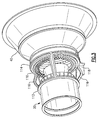
- Figure 2 schematically illustrates an isometric view of an exemplary diffuser 32 for utilization in a combustor section 30 of a gas powered turbine 10.
- the exemplary diffuser 32 includes a diffuser frame 110 containing an inner diffuser case 120. Connected to the diffuser frame 110 are multiple diffuser case sections 130.
- the gas powered turbine 10 utilizes an external combustor.
- combustor cases 140 are mounted to corresponding diffuser case sections 130.
- the external combustor is contained partially within the combustor case 140, and partially within the diffuser case defined by the combination of each of the diffuser case sections 130 and the diffuser case diffuser frame 110.
- the diffuser frame 110 is structurally connected to the compressor section 20 and the turbine section 40, and provides structural support to the diffuser 32 within the combustor section 30.
- the diffuser frame 110 includes a support rail 150.
- the support rail 150 structurally connects the diffuser frame 110 to a housing or casing of the gas powered turbine 10.
- Each of the case sections 130 is connected to the diffuser frame 110 via multiple fastener features 132.
- the fastener features 132 can be through holes operable to receive a bolt, or other fastener type, and maintain the relative positions of the diffuser frame 110 and the corresponding case section 130.
- the example diffuser 32 of Figure 2 utilizes three diffuser case sections 130. In alternate examples, any other number of diffuser case sections 130 can be utilized depending on the structural requirements of the gas powered turbine, and the loads supported by the diffuser frame 110.
- Figure 3 illustrates a diffuser frame 110 connecting a compressor section 20 of a gas powered turbine 10 to a turbine section 40 of the gas powered turbine 10.
- the diffuser frame 110 includes a forward ring 112 connected to an outlet of the compressor section 20.
- an aft ring portion 114 of the diffuser frame 110 is connected to an inlet of a turbine section 40.
- Each of the rings 112, 114 is connected to the corresponding section 20, 40 of the gas powered turbine 10 via multiple fastener features.
- the ring portions 112, 114 can be connected to alternate elements or features of the compressor section 20 and the turbine section 40 and provide similar structural support.
- Multiple diffuser frame ribs 116 extend axially between the first ring 112 and the second ring 114.
- the diffuser frame ribs 116 provide structural support to the rings 112, 114, the diffuser 32, and to the adjacent compressor section 20 and turbine section 40 while some or all of the diffuser case sections 130 (illustrated in Figure 2 ) are removed.
- the internal portions of the diffuser 32 can be accessed in situ, without removing the diffuser 32 from the gas powered turbine 10.
- a single diffuser case section 130 covering the component can be removed and the component can be accessed.
- the diffuser frame 110 provides full structural support to the gas powered turbine 10.
- the diffuser frame 110 also provides full structural support while all the diffuser case sections 130 are in an installed position.
- the structural mount 118 is a rail aligned with one of the ribs 116.
- the structural mount 118 connects the diffuser frame 110 to a housing, or case, in the example of a land based turbine.
- additional structural mounts 118 can be included and connect the gas powered turbine 10 to the housing, case or other engine support containing and supporting the gas powered turbine 10.
- the structural mount 118 can be connected to a case cowling, a pylon, or any other mounting structure.
- Figure 4 schematically illustrates an exemplary diffuser frame 110 isolated from the gas powered turbine 10.
- the diffuser frame 110 includes a first ring 112 and a second ring 114 connected by multiple ribs 116.
- An axis A is defined by each of the rings 112, 114.
- the ribs 116 are generally axially aligned.
- Each of the rings 112, 114 includes a flanged portion 210 that is radially thinner than a remainder of the ring 112, 114 relative to a centerline of the gas powered turbine 10.
- the flanged portion 210 includes multiple fastener features 212 that are configured to interface with a fastener and be sealed to a corresponding adjacent portion of the gas powered turbine via the interfaced fasteners.
- the fastener features 212 are through holes configured to interface with bolts, screws, or any similar fastener type.
- each of the ribs 116 includes two flanged portions 220.
- Each flanged portion 220 includes multiple fastener features 222.
- the fastener features 222 on the flanged portions 220 of the ribs 116 are similar in design and structure to the fastener features 212 of each of the rings 112, 114.
- the ribs 116 are bowed radially outward relative to the centerline of the gas powered turbine 10.
- the ribs 116 include a gusset 230 extending along the bowed portion. The gusset 230 increases the stiffness of the ribs 116, and provides additional structural support for the diffuser frame 110 and the gas powered turbine 10.
- the ribs 116 are straight and do not include a gusset 230.
- a structural mount 118 is also included in the diffuser frame 110.
- the structural mount 118 takes the form of a rail provided axially along one of the ribs 116.
- the structural mount 118 can be connected to one or both of the rings 112, 114 independent of the ribs 116 and provide similar structural support.
- additional structural mounts 118 can be included at one or more additional ribs 116, or at locations on the rings 112, 114 independent of the ribs 116 and provide additional structural support.
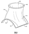
- Figure 5 illustrates an example diffuser case section 130 for utilization in the diffuser 32 of Figure 2 .
- the case section 130 includes a contoured surface 410 that partially defines an internal cavity of the diffuser 32, when the diffuser case section 130 is installed.
- the internal cavity of the diffuser is fully defined by the combination of each of the case sections 130 and the diffuser frame 110.
- the diffuser case section 130 includes fastener features 420 along diffuser edges 430. In an installed configuration, the diffuser edges 430 nest in a corresponding flanged portion 220 of the diffuser frame 110, and the fastener features 420 interface with a fastener and a corresponding fastener feature 212, 222 of the diffuser frame 110.
- the exterior contoured surface 410 of the diffuser case section 130 is flush with the corresponding ribs 116, and rings 112, 114 when in an installed position.
- the diffuser case section 130 is fastened to a radially outermost surface of the ribs 116 and rings 112, 114 and is not flush.
- the illustrated exemplary diffuser case section 130 includes a combustor opening 440 having a flange 442 for connecting to a corresponding combustor case (illustrated in Figure 6 ).
- An external combustor is housed partially within the combustor case and extends into the internal cavity of the diffuser 32 through the combustor opening 440.
- the external combustor is then interfaced with the turbine section 40 according to existing external combustor interfacing techniques, and combustion gasses are provided from the combustor to the turbine section 40.
- the combustor opening 440 and corresponding flange 442 are omitted, and the contoured surface 410 of the diffuser case section 130 is an unbroken contour.
- the specific contour of the diffuser case section 130 is selected to define sufficient internal space within the diffuser for the diffuser components.
- Figure 6 illustrates a more detailed view of an exemplary combustor case 140 for utilization with an external combustor.
- the exemplary combustor case 140 is cylindrical and extends radially outward from a corresponding diffuser case and houses a portion of the external combustor.
- Utilization of the diffuser 32 assembly described above allows the removal of outer diffuser case sections 130 that partially enclose either an annular combustor, multiple can type combustors, or an external combustor without requiring the full removal of the combustor section 30.
- the partial removal allows a worker to have access to, and to maintain, the components within the diffuser 32 and the combustor section 30 without requiring the worker to fully remove the diffuser and/or the combustor section 30.
- the structural diffuser frame 110 is a load carrying diffuser frame and facilitates the replacement of components within the combustor section.
- the construction of the diffuser frame 110 allows combustion system hardware and flow path elements, such as transition ducts, to be installed and uninstalled within the diffuser case via the removal of a single corresponding diffuser case section 130. Such an action does not require taking the gas powered turbine apart or removing it from its installed state.
- the utilization of the above described diffuser frame architecture allows for the removal and replacement of large arc sector transition ducts of greater than 60 degrees.
- the flow path of the diffuser case is closed via the diffuser case sections that are fastened to the diffuser frame individually, thereby allowing the above described removal of a single diffuser section.
- the diffuser sections are non-load bearing and the full structural load on the diffuser is born by the diffuser frame.
- Figure 7 illustrates a flowchart 600 demonstrating a maintenance process for a gas powered turbine incorporating the diffuser assembly of Figure 2 .
- a maintenance worker In order to remove and service a component contained within the diffuser 32, a maintenance worker initially opens the case/housing containing the gas powered turbine 10 at an "Open Case/Housing" step 610.
- a diffuser case section 130 is removed from the diffuser 32 in a "Remove Diffuser Case Section” step 620.
- the maintenance worker can access the components within the diffuser 32, while the diffuser case diffuser frame 110 provides structural support thereby preventing damage or fatigue to a remainder of the gas powered turbine 10.
- the worker services the component in a "Service Component" step 630. The service is performed with the gas powered turbine in situ, thereby reducing time, effort, and monetary costs associated with performing the maintenance.
- the maintenance worker replaces the diffuser case section 130 in a "Replace Diffuser Case Section” step 640, and closes the case/housing in a "Close Case/Housing" step 650.
Landscapes
- Engineering & Computer Science (AREA)
- Mechanical Engineering (AREA)
- General Engineering & Computer Science (AREA)
- Chemical & Material Sciences (AREA)
- Combustion & Propulsion (AREA)
- Physics & Mathematics (AREA)
- Fluid Mechanics (AREA)
- Structures Of Non-Positive Displacement Pumps (AREA)
Abstract
Description
- The present disclosure relates generally to gas powered turbines and more specifically to a diffuser case for the same.
- Gas powered turbines, such as those utilized in industrial land based applications, utilize a compressor to compress a gas, a combustor to mix the compressed gas with a fuel and ignite the mixture, and a turbine across which the resultant combustion gasses are expanded. Expansion of the combustion gasses across the turbine section drives the turbine section to rotate. The rotation is translated to a shaft which outputs rotational motion from the gas powered turbine. The output shaft is, in some examples, connected to an electrical generator that converts the rotational motion into electrical energy.
- Each of the sections includes internal components that require maintenance over the life span of the gas powered turbine. In order to access the internal components, the entire section being serviced is removed from the gas powered turbine and disassembled. The repaired or replaced component is then reinstalled, and the gas powered turbine is reassembled.
- In one exemplary embodiment a turbine engine includes a diffuser connecting a compressor section and a turbine section, and the diffuser includes a diffuser frame and a plurality of diffuser case sections connected to the diffuser frame.
- In another exemplary embodiment of the above described turbine engine the diffuser frame includes a first ring, a second ring, and a plurality of structural ribs connecting the first ring and the second ring.
- In another exemplary embodiment of any of the above described turbine engines, one of the first ring and the second ring is connected to a compressor section and the other of the first ring and the second ring is connected to a turbine section.
- In another exemplary embodiment of any of the above described turbine engines, each of the ribs includes at least one fastening feature configured to interface with one of the diffuser case sections.
- In another exemplary embodiment of any of the above described turbine engines, the first ring includes a flanged portion radially thinner than a remainder of the first ring and the second ring includes a flanged portion radially thinner than a remainder of the second ring.
- In another exemplary embodiment of any of the above described turbine engines, each of the ribs includes at least one flange portion, and wherein the at least one flange portion is radially thinner than a remainder of the corresponding rib.
- In another exemplary embodiment of any of the above described turbine engines, each of the ribs bows radially outward relative to a centerline of the turbine engine.
- In another exemplary embodiment of any of the above described turbine engines, each of the ribs further comprises a gusset extending radially inward from the rib at the bow.
- In another exemplary embodiment of any of the above described turbine engines, the diffuser frame further comprises at least one structural mount structurally connecting the diffuser frame to an engine support.
- Another exemplary embodiment of any of the above described turbine engines further includes at least one combustor case extending radially outward from at least one of the diffuser case sections.
- Another exemplary embodiment of any of the above described turbine engines further includes an external combustor disposed at least partially within the combustor case.
- In another exemplary embodiment of any of the above described turbine engines, the external combustor is disposed partially within the combustor case and partially within a corresponding diffuser case section.
- In another exemplary embodiment of any of the above described turbine engines, the diffuser comprises an internal cavity defined by the frame and the plurality of diffuser case sections.
- In another exemplary embodiment of any of the above described turbine engines, at least one of the diffuser case sections includes an unbroken contour at an exterior surface.
- In another exemplary embodiment of any of the above described turbine engines, the diffuser frame is a structural support configured to at least partially support the turbine engine while at least one diffuser case section is removed.
- In another exemplary embodiment of any of the above described turbine engines, the diffuser frame is a structural support configured to provide full structural support to a combustor portion of the turbine engine while at least one diffuser case section is removed.
- An exemplary method for maintaining a turbine engine, such as that described above in any embodiment, includes removing a diffuser case section while the turbine engine is in situ, accessing a component, servicing the component, and replacing the diffuser case section.
- Another example of the above described exemplary method further includes providing structural support to the turbine engine using a diffuser case frame, such as that described above in any embodiment.
- In one exemplary embodiment a land based turbine engine includes a compressor section, a combustor section fluidly connected to the compressor section, a turbine section fluidly connected to the combustor section, and a diffuser disposed in the combustor section, the diffuser including a structural diffuser frame configured to structurally support the combustor section.
- In another example of the above described land based turbine engine, the diffuser further including a plurality of diffuser case sections connected to the diffuser frame.
- These and other features of the present invention can be best understood from the following specification and drawings, the following of which is a brief description.
-
-
Figure 1 schematically illustrates a gas powered turbine. -
Figure 2 schematically illustrates an exemplary diffuser assembly for the gas powered turbine ofFigure 1 . -
Figure 3 schematically illustrates a partial installation of the exemplary diffuser assembly ofFigure 2 . -
Figure 4 schematically illustrates an isometric view of an example diffuser frame. -
Figure 5 schematically illustrates an exemplary diffuser case section. -
Figure 6 schematically illustrates an exemplary combustor case. -
Figure 7 illustrates a flowchart demonstrating a maintenance method for a gas powered turbine incorporating the diffuser assembly ofFigure 2 . -
Figure 1 schematically illustrates a land based gas poweredturbine 10. The gas poweredturbine 10 includes acompressor section 20, acombustor section 30, and aturbine section 40. Thecombustor section 30 includes adiffuser 32. Arotational shaft 50 is connected to theturbine section 40. During operation, gasses within thecombustor section 30 are combined with a fuel and ignited. The resultant combustion gasses are passed through thediffuser 32 and provided to theturbine section 40. As the combustion gasses expand across theturbine section 40, theturbine section 40 is driven to rotate, which in turn rotates theshaft 50. Theshaft 50 extends to thecompressor section 20 and drives thecompressor section 20 to rotate as well. Anoutput shaft 52 is mechanically interfaced with theshaft 50 of the gas poweredturbine 10, and provides a rotational output from the gas poweredturbine 10 to an external system. - Over the lifespan of the gas powered
turbine 10 components within the gas poweredturbine 10 wear out and need to be replaced and/or repaired. In existing gas powered turbines, in order to repair or replace thediffuser 32, or a component contained within a diffuser, theentire combustor section 30 must be removed from the gas powered turbine. Removal of thecombustor section 30 requires disassembly of a majority of the gas poweredturbine 10. - With continued reference to
Figure 1, Figure 2 schematically illustrates an isometric view of anexemplary diffuser 32 for utilization in acombustor section 30 of a gas poweredturbine 10. Theexemplary diffuser 32 includes adiffuser frame 110 containing aninner diffuser case 120. Connected to thediffuser frame 110 are multiplediffuser case sections 130. In some examples, such as the illustrated example, the gas poweredturbine 10 utilizes an external combustor. In such an example,combustor cases 140 are mounted to correspondingdiffuser case sections 130. The external combustor is contained partially within thecombustor case 140, and partially within the diffuser case defined by the combination of each of thediffuser case sections 130 and the diffusercase diffuser frame 110. In an installed configuration, thediffuser frame 110 is structurally connected to thecompressor section 20 and theturbine section 40, and provides structural support to thediffuser 32 within thecombustor section 30. In some examples, thediffuser frame 110 includes asupport rail 150. Thesupport rail 150 structurally connects thediffuser frame 110 to a housing or casing of the gas poweredturbine 10. - Each of the
case sections 130 is connected to thediffuser frame 110 via multiple fastener features 132. By way of example, thefastener features 132 can be through holes operable to receive a bolt, or other fastener type, and maintain the relative positions of thediffuser frame 110 and thecorresponding case section 130. - The example diffuser 32 of
Figure 2 utilizes threediffuser case sections 130. In alternate examples, any other number ofdiffuser case sections 130 can be utilized depending on the structural requirements of the gas powered turbine, and the loads supported by thediffuser frame 110. - With continued reference to
Figures 1 and 2 ,Figure 3 illustrates adiffuser frame 110 connecting acompressor section 20 of a gas poweredturbine 10 to aturbine section 40 of the gas poweredturbine 10. Thediffuser frame 110 includes aforward ring 112 connected to an outlet of thecompressor section 20. Similarly, anaft ring portion 114 of thediffuser frame 110 is connected to an inlet of aturbine section 40. Each of therings section turbine 10 via multiple fastener features. In alternative examples, thering portions compressor section 20 and theturbine section 40 and provide similar structural support. - Multiple
diffuser frame ribs 116 extend axially between thefirst ring 112 and thesecond ring 114. Thediffuser frame ribs 116 provide structural support to therings diffuser 32, and to theadjacent compressor section 20 andturbine section 40 while some or all of the diffuser case sections 130 (illustrated inFigure 2 ) are removed. In this way, the internal portions of thediffuser 32 can be accessed in situ, without removing thediffuser 32 from the gas poweredturbine 10. By way of example, when an internal diffuser or combustor component requires servicing, a singlediffuser case section 130 covering the component can be removed and the component can be accessed. While thecase section 130 is removed, thediffuser frame 110 provides full structural support to the gas poweredturbine 10. In some examples, thediffuser frame 110 also provides full structural support while all thediffuser case sections 130 are in an installed position. - Further incorporated into the
diffuser frame 110 is astructural mount 118. In one example, thestructural mount 118 is a rail aligned with one of theribs 116. Thestructural mount 118 connects thediffuser frame 110 to a housing, or case, in the example of a land based turbine. In alternative examples, additionalstructural mounts 118 can be included and connect the gas poweredturbine 10 to the housing, case or other engine support containing and supporting the gas poweredturbine 10. By way of example, if the gas poweredturbine 10 is included within a geared turbofan engine or any other type of aircraft engine, thestructural mount 118 can be connected to a case cowling, a pylon, or any other mounting structure. - With continued reference to
Figures 1-3 ,Figure 4 schematically illustrates anexemplary diffuser frame 110 isolated from the gas poweredturbine 10. As described above, thediffuser frame 110 includes afirst ring 112 and asecond ring 114 connected bymultiple ribs 116. An axis A is defined by each of therings ribs 116 are generally axially aligned. Each of therings flanged portion 210 that is radially thinner than a remainder of thering turbine 10. Theflanged portion 210 includes multiple fastener features 212 that are configured to interface with a fastener and be sealed to a corresponding adjacent portion of the gas powered turbine via the interfaced fasteners. In one example, the fastener features 212 are through holes configured to interface with bolts, screws, or any similar fastener type. - Similarly, each of the
ribs 116 includes twoflanged portions 220. Eachflanged portion 220 includes multiple fastener features 222. The fastener features 222 on theflanged portions 220 of theribs 116 are similar in design and structure to the fastener features 212 of each of therings ribs 116 are bowed radially outward relative to the centerline of the gas poweredturbine 10. In some examples theribs 116 include agusset 230 extending along the bowed portion. Thegusset 230 increases the stiffness of theribs 116, and provides additional structural support for thediffuser frame 110 and the gas poweredturbine 10. In other examples, theribs 116 are straight and do not include agusset 230. Also included in thediffuser frame 110 is astructural mount 118. In the example ofFigure 4 , thestructural mount 118 takes the form of a rail provided axially along one of theribs 116. - Depending on the design of the particular gas powered
turbine 10, thestructural mount 118 can be connected to one or both of therings ribs 116 and provide similar structural support. In a further example, additionalstructural mounts 118 can be included at one or moreadditional ribs 116, or at locations on therings ribs 116 and provide additional structural support. - With continued reference to
Figures 1-4 ,Figure 5 illustrates an examplediffuser case section 130 for utilization in thediffuser 32 ofFigure 2 . Thecase section 130 includes acontoured surface 410 that partially defines an internal cavity of thediffuser 32, when thediffuser case section 130 is installed. The internal cavity of the diffuser is fully defined by the combination of each of thecase sections 130 and thediffuser frame 110. Thediffuser case section 130 includes fastener features 420 along diffuser edges 430. In an installed configuration, the diffuser edges 430 nest in a correspondingflanged portion 220 of thediffuser frame 110, and the fastener features 420 interface with a fastener and acorresponding fastener feature diffuser frame 110. In some examples the exterior contouredsurface 410 of thediffuser case section 130 is flush with thecorresponding ribs 116, and rings 112, 114 when in an installed position. In alternative examples, thediffuser case section 130 is fastened to a radially outermost surface of theribs 116 and rings 112, 114 and is not flush. - The illustrated exemplary
diffuser case section 130 includes acombustor opening 440 having aflange 442 for connecting to a corresponding combustor case (illustrated inFigure 6 ). An external combustor is housed partially within the combustor case and extends into the internal cavity of thediffuser 32 through thecombustor opening 440. The external combustor is then interfaced with theturbine section 40 according to existing external combustor interfacing techniques, and combustion gasses are provided from the combustor to theturbine section 40. - In alternative examples utilizing an internal combustor rather than an external combustor, the
combustor opening 440 andcorresponding flange 442 are omitted, and thecontoured surface 410 of thediffuser case section 130 is an unbroken contour. The specific contour of thediffuser case section 130 is selected to define sufficient internal space within the diffuser for the diffuser components. - With continued reference to
Figures 1-5 ,Figure 6 illustrates a more detailed view of anexemplary combustor case 140 for utilization with an external combustor. Theexemplary combustor case 140 is cylindrical and extends radially outward from a corresponding diffuser case and houses a portion of the external combustor. - Utilization of the
diffuser 32 assembly described above allows the removal of outerdiffuser case sections 130 that partially enclose either an annular combustor, multiple can type combustors, or an external combustor without requiring the full removal of thecombustor section 30. The partial removal allows a worker to have access to, and to maintain, the components within thediffuser 32 and thecombustor section 30 without requiring the worker to fully remove the diffuser and/or thecombustor section 30. Thestructural diffuser frame 110 is a load carrying diffuser frame and facilitates the replacement of components within the combustor section. - The construction of the
diffuser frame 110 allows combustion system hardware and flow path elements, such as transition ducts, to be installed and uninstalled within the diffuser case via the removal of a single correspondingdiffuser case section 130. Such an action does not require taking the gas powered turbine apart or removing it from its installed state. In some examples, the utilization of the above described diffuser frame architecture allows for the removal and replacement of large arc sector transition ducts of greater than 60 degrees. - The flow path of the diffuser case is closed via the diffuser case sections that are fastened to the diffuser frame individually, thereby allowing the above described removal of a single diffuser section. In some examples, the diffuser sections are non-load bearing and the full structural load on the diffuser is born by the diffuser frame.
- With continued reference to
Figures 1-6 ,Figure 7 illustrates a flowchart 600 demonstrating a maintenance process for a gas powered turbine incorporating the diffuser assembly ofFigure 2 . In order to remove and service a component contained within thediffuser 32, a maintenance worker initially opens the case/housing containing the gas poweredturbine 10 at an "Open Case/Housing"step 610. - Once the case or housing is opened, a
diffuser case section 130 is removed from thediffuser 32 in a "Remove Diffuser Case Section"step 620. Once thediffuser case section 130 has been removed, the maintenance worker can access the components within thediffuser 32, while the diffusercase diffuser frame 110 provides structural support thereby preventing damage or fatigue to a remainder of the gas poweredturbine 10. Once the maintenance worker has access to the component, the worker services the component in a "Service Component"step 630. The service is performed with the gas powered turbine in situ, thereby reducing time, effort, and monetary costs associated with performing the maintenance. - After the servicing has been completed, the maintenance worker replaces the
diffuser case section 130 in a "Replace Diffuser Case Section"step 640, and closes the case/housing in a "Close Case/Housing"step 650. - While described above with regards to a land based gas powered turbine, one of skill in the art will understand that the structures and concepts described herein can be applied to aircraft engines, marine engines, or any other gas powered turbine structures with minimal modification.
- It is further understood that any of the above described concepts can be used alone or in combination with any or all of the other above described concepts. Although an embodiment of this invention has been disclosed, a worker of ordinary skill in this art would recognize that certain modifications would come within the scope of this invention. For that reason, the following claims should be studied to determine the true scope and content of this invention.
Claims (15)
- A turbine engine (10) comprising:a diffuser (32) connecting a compressor section (20) and a turbine section (40); andthe diffuser (32) comprising a diffuser frame (110) and a plurality of diffuser case sections (130) connected to the diffuser frame (110).
- The turbine engine (10) of claim 1, wherein the diffuser frame (110) comprises a first ring (112), a second ring (114), and a plurality of structural ribs (116) connecting said first ring (112) and said second ring (114).
- The turbine engine (10) of claim 2, wherein one of said first ring (112) and said second ring (114) is connected to a compressor section (20) and the other of said first ring (112) and said second ring (114) is connected to a turbine section (40).
- The turbine engine (10) of claim 2 or 3, wherein each of said ribs (116) includes at least one fastening feature (212) configured to interface with one of said diffuser case sections (130).
- The turbine engine (10) of claim 2, 3 or 4, wherein said first ring (112) comprises a flanged portion (210) radially thinner than a remainder of said first ring (112) and said second ring (114) comprises a flanged portion (210) radially thinner than a remainder of said second ring (114).
- The turbine engine (10) of any of claims 2 to 5, wherein each of said ribs (116) comprises at least one flange portion (220), and wherein said at least one flange portion (220) is radially thinner than a remainder of the corresponding rib (116).
- The turbine engine (10) of any of claims 2 to 6, wherein each of said ribs (116) bows radially outward relative to a centerline (A) of the turbine engine (10), optionally wherein each of said ribs (116) further comprises a gusset (230) extending radially inward from the rib (116) at the bow.
- The turbine engine (10) of any preceding claim, wherein said diffuser frame (32) further comprises at least one structural mount (118) structurally connecting the diffuser frame (110) to an engine support.
- The turbine engine (10) of any preceding claim, further comprising at least one combustor case (140) extending radially outward from at least one of said diffuser case sections (130).
- The turbine engine (10) of claim 9, further comprising an external combustor disposed at least partially within said combustor case (130), optionally wherein the external combustor is disposed partially within said combustor case (140) and partially within a corresponding diffuser case section (130).
- The turbine engine (10) of any preceding claim, wherein the diffuser (32) comprises an internal cavity defined by the frame (110) and the plurality of diffuser case sections (130).
- The turbine engine (10) of any preceding claim, wherein at least one of said diffuser case sections (130) includes an unbroken contour at an exterior surface (410).
- The turbine engine (10) of any preceding claim, wherein the diffuser frame (110) is a structural support configured to at least partially support said turbine engine (10) while at least one diffuser case section (130) is removed, optionally wherein the diffuser frame (110) is a structural support configured to provide full structural support to a combustor portion (30) of the turbine engine (10) while at least one diffuser case section (130) is removed.
- A method for maintaining a turbine engine (10) comprising:removing a diffuser case section (130) while said turbine engine (10) is in situ;accessing a component;servicing said component; andreplacing said diffuser case section (30), and optionally further comprising providing structural support to the turbine engine (10) using a diffuser case frame (110).
- A land based turbine engine (10) comprising:a compressor section (20);a combustor section (30) fluidly connected to the compressor section (20);a turbine section (40) fluidly connected to the combustor section (30); anda diffuser (32) disposed in said combustor section (30), the diffuser (32) including a structural diffuser frame (110) configured to structurally support said combustor section (30), wherein the diffuser (32) optionally further includes a plurality of diffuser case sections (130) connected to the diffuser frame (110).
Applications Claiming Priority (1)
| Application Number | Priority Date | Filing Date | Title |
|---|---|---|---|
| US14/805,536 US10473117B2 (en) | 2015-07-22 | 2015-07-22 | Diffuser case for a gas powered turbine |
Publications (2)
| Publication Number | Publication Date |
|---|---|
| EP3121381A1 true EP3121381A1 (en) | 2017-01-25 |
| EP3121381B1 EP3121381B1 (en) | 2020-10-14 |
Family
ID=56511419
Family Applications (1)
| Application Number | Title | Priority Date | Filing Date |
|---|---|---|---|
| EP16180901.7A Active EP3121381B1 (en) | 2015-07-22 | 2016-07-22 | Turbine engine and method of maintaining a turbine engine |
Country Status (2)
| Country | Link |
|---|---|
| US (1) | US10473117B2 (en) |
| EP (1) | EP3121381B1 (en) |
Citations (5)
| Publication number | Priority date | Publication date | Assignee | Title |
|---|---|---|---|---|
| US3327473A (en) * | 1966-01-11 | 1967-06-27 | Gen Motors Corp | Engine support structure |
| US3650106A (en) * | 1968-10-18 | 1972-03-21 | Bennes Marrel Sa | Combustion chamber for gas turbine |
| US5572863A (en) * | 1994-09-15 | 1996-11-12 | Rolls-Royce Plc | Resilient annular mounting member for a transition duct of a combustion chamber |
| WO2008037554A2 (en) * | 2006-09-26 | 2008-04-03 | Siemens Aktiengesellschaft | Improvements in or relating to gas turbine engines |
| WO2013052438A1 (en) * | 2011-10-04 | 2013-04-11 | Siemens Energy, Inc. | Casing for a gas turbine engine |
Family Cites Families (5)
| Publication number | Priority date | Publication date | Assignee | Title |
|---|---|---|---|---|
| US8118251B2 (en) | 2008-01-18 | 2012-02-21 | United Technologies Corporation | Mounting system for a gas turbine engine |
| US8167237B2 (en) | 2008-03-21 | 2012-05-01 | United Technologies Corporation | Mounting system for a gas turbine engine |
| US8528176B2 (en) | 2008-10-24 | 2013-09-10 | Pratt & Whitney Canada Corp. | Diffuser case removal apparatus and method |
| US9435259B2 (en) | 2012-02-27 | 2016-09-06 | United Technologies Corporation | Gas turbine engine cooling system |
| WO2015066473A1 (en) | 2013-11-04 | 2015-05-07 | United Technologies Corporation | Inner diffuser case for a gas turbine engine |
-
2015
- 2015-07-22 US US14/805,536 patent/US10473117B2/en active Active
-
2016
- 2016-07-22 EP EP16180901.7A patent/EP3121381B1/en active Active
Patent Citations (5)
| Publication number | Priority date | Publication date | Assignee | Title |
|---|---|---|---|---|
| US3327473A (en) * | 1966-01-11 | 1967-06-27 | Gen Motors Corp | Engine support structure |
| US3650106A (en) * | 1968-10-18 | 1972-03-21 | Bennes Marrel Sa | Combustion chamber for gas turbine |
| US5572863A (en) * | 1994-09-15 | 1996-11-12 | Rolls-Royce Plc | Resilient annular mounting member for a transition duct of a combustion chamber |
| WO2008037554A2 (en) * | 2006-09-26 | 2008-04-03 | Siemens Aktiengesellschaft | Improvements in or relating to gas turbine engines |
| WO2013052438A1 (en) * | 2011-10-04 | 2013-04-11 | Siemens Energy, Inc. | Casing for a gas turbine engine |
Also Published As
| Publication number | Publication date |
|---|---|
| EP3121381B1 (en) | 2020-10-14 |
| US10473117B2 (en) | 2019-11-12 |
| US20170023015A1 (en) | 2017-01-26 |
Similar Documents
| Publication | Publication Date | Title |
|---|---|---|
| US10329956B2 (en) | Multi-function boss for a turbine exhaust case | |
| EP2078826B1 (en) | Gas turbine engine case | |
| US6401448B1 (en) | System for mounting aircraft engines | |
| US8943840B2 (en) | Mounting assembly | |
| US20140373556A1 (en) | Support structure for a gas turbine engine | |
| EP2938847B1 (en) | Installation mounts for a turbine exhaust case | |
| EP2938860B1 (en) | Turbine exhaust case multi-piece frame | |
| US20080073460A1 (en) | Aeroengine mount | |
| US10473030B2 (en) | Acoustic panel of turbine engine | |
| US10612564B2 (en) | Acoustic panel of turbine engine and method of arranging the acoustic panel | |
| US20200284197A1 (en) | Gas turbine engine front center body architecture | |
| EP3549856A1 (en) | Fan cowl latch concept for fuselage mounted power plant | |
| US12601294B2 (en) | Gas turbine engine front center body architecture | |
| EP2938861A1 (en) | Gas turbine engine nosecone attachment structure | |
| US10329957B2 (en) | Turbine exhaust case multi-piece framed | |
| EP2735708B1 (en) | Aeroengine sealing arrangement | |
| US10473036B2 (en) | Bleed valve with neutral or closing bias | |
| EP3121381B1 (en) | Turbine engine and method of maintaining a turbine engine | |
| EP3059395B1 (en) | Combustor aft mount assembly |
Legal Events
| Date | Code | Title | Description |
|---|---|---|---|
| PUAI | Public reference made under article 153(3) epc to a published international application that has entered the european phase |
Free format text: ORIGINAL CODE: 0009012 |
|
| STAA | Information on the status of an ep patent application or granted ep patent |
Free format text: STATUS: THE APPLICATION HAS BEEN PUBLISHED |
|
| AK | Designated contracting states |
Kind code of ref document: A1 Designated state(s): AL AT BE BG CH CY CZ DE DK EE ES FI FR GB GR HR HU IE IS IT LI LT LU LV MC MK MT NL NO PL PT RO RS SE SI SK SM TR |
|
| AX | Request for extension of the european patent |
Extension state: BA ME |
|
| STAA | Information on the status of an ep patent application or granted ep patent |
Free format text: STATUS: REQUEST FOR EXAMINATION WAS MADE |
|
| 17P | Request for examination filed |
Effective date: 20170725 |
|
| RBV | Designated contracting states (corrected) |
Designated state(s): AL AT BE BG CH CY CZ DE DK EE ES FI FR GB GR HR HU IE IS IT LI LT LU LV MC MK MT NL NO PL PT RO RS SE SI SK SM TR |
|
| GRAP | Despatch of communication of intention to grant a patent |
Free format text: ORIGINAL CODE: EPIDOSNIGR1 |
|
| STAA | Information on the status of an ep patent application or granted ep patent |
Free format text: STATUS: GRANT OF PATENT IS INTENDED |
|
| INTG | Intention to grant announced |
Effective date: 20200424 |
|
| GRAS | Grant fee paid |
Free format text: ORIGINAL CODE: EPIDOSNIGR3 |
|
| GRAA | (expected) grant |
Free format text: ORIGINAL CODE: 0009210 |
|
| STAA | Information on the status of an ep patent application or granted ep patent |
Free format text: STATUS: THE PATENT HAS BEEN GRANTED |
|
| AK | Designated contracting states |
Kind code of ref document: B1 Designated state(s): AL AT BE BG CH CY CZ DE DK EE ES FI FR GB GR HR HU IE IS IT LI LT LU LV MC MK MT NL NO PL PT RO RS SE SI SK SM TR |
|
| REG | Reference to a national code |
Ref country code: GB Ref legal event code: FG4D |
|
| REG | Reference to a national code |
Ref country code: AT Ref legal event code: REF Ref document number: 1323796 Country of ref document: AT Kind code of ref document: T Effective date: 20201015 Ref country code: CH Ref legal event code: EP |
|
| REG | Reference to a national code |
Ref country code: DE Ref legal event code: R096 Ref document number: 602016045714 Country of ref document: DE |
|
| REG | Reference to a national code |
Ref country code: IE Ref legal event code: FG4D |
|
| REG | Reference to a national code |
Ref country code: AT Ref legal event code: MK05 Ref document number: 1323796 Country of ref document: AT Kind code of ref document: T Effective date: 20201014 |
|
| REG | Reference to a national code |
Ref country code: NL Ref legal event code: MP Effective date: 20201014 |
|
| RAP2 | Party data changed (patent owner data changed or rights of a patent transferred) |
Owner name: RAYTHEON TECHNOLOGIES CORPORATION |
|
| PG25 | Lapsed in a contracting state [announced via postgrant information from national office to epo] |
Ref country code: NO Free format text: LAPSE BECAUSE OF FAILURE TO SUBMIT A TRANSLATION OF THE DESCRIPTION OR TO PAY THE FEE WITHIN THE PRESCRIBED TIME-LIMIT Effective date: 20210114 Ref country code: NL Free format text: LAPSE BECAUSE OF FAILURE TO SUBMIT A TRANSLATION OF THE DESCRIPTION OR TO PAY THE FEE WITHIN THE PRESCRIBED TIME-LIMIT Effective date: 20201014 Ref country code: PT Free format text: LAPSE BECAUSE OF FAILURE TO SUBMIT A TRANSLATION OF THE DESCRIPTION OR TO PAY THE FEE WITHIN THE PRESCRIBED TIME-LIMIT Effective date: 20210215 Ref country code: RS Free format text: LAPSE BECAUSE OF FAILURE TO SUBMIT A TRANSLATION OF THE DESCRIPTION OR TO PAY THE FEE WITHIN THE PRESCRIBED TIME-LIMIT Effective date: 20201014 Ref country code: GR Free format text: LAPSE BECAUSE OF FAILURE TO SUBMIT A TRANSLATION OF THE DESCRIPTION OR TO PAY THE FEE WITHIN THE PRESCRIBED TIME-LIMIT Effective date: 20210115 Ref country code: FI Free format text: LAPSE BECAUSE OF FAILURE TO SUBMIT A TRANSLATION OF THE DESCRIPTION OR TO PAY THE FEE WITHIN THE PRESCRIBED TIME-LIMIT Effective date: 20201014 |
|
| REG | Reference to a national code |
Ref country code: LT Ref legal event code: MG4D |
|
| PG25 | Lapsed in a contracting state [announced via postgrant information from national office to epo] |
Ref country code: PL Free format text: LAPSE BECAUSE OF FAILURE TO SUBMIT A TRANSLATION OF THE DESCRIPTION OR TO PAY THE FEE WITHIN THE PRESCRIBED TIME-LIMIT Effective date: 20201014 Ref country code: IS Free format text: LAPSE BECAUSE OF FAILURE TO SUBMIT A TRANSLATION OF THE DESCRIPTION OR TO PAY THE FEE WITHIN THE PRESCRIBED TIME-LIMIT Effective date: 20210214 Ref country code: LV Free format text: LAPSE BECAUSE OF FAILURE TO SUBMIT A TRANSLATION OF THE DESCRIPTION OR TO PAY THE FEE WITHIN THE PRESCRIBED TIME-LIMIT Effective date: 20201014 Ref country code: SE Free format text: LAPSE BECAUSE OF FAILURE TO SUBMIT A TRANSLATION OF THE DESCRIPTION OR TO PAY THE FEE WITHIN THE PRESCRIBED TIME-LIMIT Effective date: 20201014 Ref country code: BG Free format text: LAPSE BECAUSE OF FAILURE TO SUBMIT A TRANSLATION OF THE DESCRIPTION OR TO PAY THE FEE WITHIN THE PRESCRIBED TIME-LIMIT Effective date: 20210114 Ref country code: ES Free format text: LAPSE BECAUSE OF FAILURE TO SUBMIT A TRANSLATION OF THE DESCRIPTION OR TO PAY THE FEE WITHIN THE PRESCRIBED TIME-LIMIT Effective date: 20201014 Ref country code: AT Free format text: LAPSE BECAUSE OF FAILURE TO SUBMIT A TRANSLATION OF THE DESCRIPTION OR TO PAY THE FEE WITHIN THE PRESCRIBED TIME-LIMIT Effective date: 20201014 |
|
| PG25 | Lapsed in a contracting state [announced via postgrant information from national office to epo] |
Ref country code: HR Free format text: LAPSE BECAUSE OF FAILURE TO SUBMIT A TRANSLATION OF THE DESCRIPTION OR TO PAY THE FEE WITHIN THE PRESCRIBED TIME-LIMIT Effective date: 20201014 |
|
| REG | Reference to a national code |
Ref country code: DE Ref legal event code: R097 Ref document number: 602016045714 Country of ref document: DE |
|
| PG25 | Lapsed in a contracting state [announced via postgrant information from national office to epo] |
Ref country code: LT Free format text: LAPSE BECAUSE OF FAILURE TO SUBMIT A TRANSLATION OF THE DESCRIPTION OR TO PAY THE FEE WITHIN THE PRESCRIBED TIME-LIMIT Effective date: 20201014 Ref country code: SM Free format text: LAPSE BECAUSE OF FAILURE TO SUBMIT A TRANSLATION OF THE DESCRIPTION OR TO PAY THE FEE WITHIN THE PRESCRIBED TIME-LIMIT Effective date: 20201014 Ref country code: EE Free format text: LAPSE BECAUSE OF FAILURE TO SUBMIT A TRANSLATION OF THE DESCRIPTION OR TO PAY THE FEE WITHIN THE PRESCRIBED TIME-LIMIT Effective date: 20201014 Ref country code: CZ Free format text: LAPSE BECAUSE OF FAILURE TO SUBMIT A TRANSLATION OF THE DESCRIPTION OR TO PAY THE FEE WITHIN THE PRESCRIBED TIME-LIMIT Effective date: 20201014 Ref country code: SK Free format text: LAPSE BECAUSE OF FAILURE TO SUBMIT A TRANSLATION OF THE DESCRIPTION OR TO PAY THE FEE WITHIN THE PRESCRIBED TIME-LIMIT Effective date: 20201014 Ref country code: RO Free format text: LAPSE BECAUSE OF FAILURE TO SUBMIT A TRANSLATION OF THE DESCRIPTION OR TO PAY THE FEE WITHIN THE PRESCRIBED TIME-LIMIT Effective date: 20201014 |
|
| PLBE | No opposition filed within time limit |
Free format text: ORIGINAL CODE: 0009261 |
|
| STAA | Information on the status of an ep patent application or granted ep patent |
Free format text: STATUS: NO OPPOSITION FILED WITHIN TIME LIMIT |
|
| PG25 | Lapsed in a contracting state [announced via postgrant information from national office to epo] |
Ref country code: DK Free format text: LAPSE BECAUSE OF FAILURE TO SUBMIT A TRANSLATION OF THE DESCRIPTION OR TO PAY THE FEE WITHIN THE PRESCRIBED TIME-LIMIT Effective date: 20201014 |
|
| 26N | No opposition filed |
Effective date: 20210715 |
|
| PG25 | Lapsed in a contracting state [announced via postgrant information from national office to epo] |
Ref country code: IT Free format text: LAPSE BECAUSE OF FAILURE TO SUBMIT A TRANSLATION OF THE DESCRIPTION OR TO PAY THE FEE WITHIN THE PRESCRIBED TIME-LIMIT Effective date: 20201014 Ref country code: AL Free format text: LAPSE BECAUSE OF FAILURE TO SUBMIT A TRANSLATION OF THE DESCRIPTION OR TO PAY THE FEE WITHIN THE PRESCRIBED TIME-LIMIT Effective date: 20201014 |
|
| PG25 | Lapsed in a contracting state [announced via postgrant information from national office to epo] |
Ref country code: SI Free format text: LAPSE BECAUSE OF FAILURE TO SUBMIT A TRANSLATION OF THE DESCRIPTION OR TO PAY THE FEE WITHIN THE PRESCRIBED TIME-LIMIT Effective date: 20201014 |
|
| REG | Reference to a national code |
Ref country code: CH Ref legal event code: PL |
|
| PG25 | Lapsed in a contracting state [announced via postgrant information from national office to epo] |
Ref country code: MC Free format text: LAPSE BECAUSE OF FAILURE TO SUBMIT A TRANSLATION OF THE DESCRIPTION OR TO PAY THE FEE WITHIN THE PRESCRIBED TIME-LIMIT Effective date: 20201014 |
|
| REG | Reference to a national code |
Ref country code: BE Ref legal event code: MM Effective date: 20210731 |
|
| PG25 | Lapsed in a contracting state [announced via postgrant information from national office to epo] |
Ref country code: LI Free format text: LAPSE BECAUSE OF NON-PAYMENT OF DUE FEES Effective date: 20210731 Ref country code: CH Free format text: LAPSE BECAUSE OF NON-PAYMENT OF DUE FEES Effective date: 20210731 |
|
| PG25 | Lapsed in a contracting state [announced via postgrant information from national office to epo] |
Ref country code: IS Free format text: LAPSE BECAUSE OF FAILURE TO SUBMIT A TRANSLATION OF THE DESCRIPTION OR TO PAY THE FEE WITHIN THE PRESCRIBED TIME-LIMIT Effective date: 20210214 Ref country code: LU Free format text: LAPSE BECAUSE OF NON-PAYMENT OF DUE FEES Effective date: 20210722 |
|
| PG25 | Lapsed in a contracting state [announced via postgrant information from national office to epo] |
Ref country code: IE Free format text: LAPSE BECAUSE OF NON-PAYMENT OF DUE FEES Effective date: 20210722 Ref country code: BE Free format text: LAPSE BECAUSE OF NON-PAYMENT OF DUE FEES Effective date: 20210731 |
|
| PG25 | Lapsed in a contracting state [announced via postgrant information from national office to epo] |
Ref country code: HU Free format text: LAPSE BECAUSE OF FAILURE TO SUBMIT A TRANSLATION OF THE DESCRIPTION OR TO PAY THE FEE WITHIN THE PRESCRIBED TIME-LIMIT; INVALID AB INITIO Effective date: 20160722 |
|
| P01 | Opt-out of the competence of the unified patent court (upc) registered |
Effective date: 20230520 |
|
| PG25 | Lapsed in a contracting state [announced via postgrant information from national office to epo] |
Ref country code: CY Free format text: LAPSE BECAUSE OF FAILURE TO SUBMIT A TRANSLATION OF THE DESCRIPTION OR TO PAY THE FEE WITHIN THE PRESCRIBED TIME-LIMIT Effective date: 20201014 |
|
| PG25 | Lapsed in a contracting state [announced via postgrant information from national office to epo] |
Ref country code: MK Free format text: LAPSE BECAUSE OF FAILURE TO SUBMIT A TRANSLATION OF THE DESCRIPTION OR TO PAY THE FEE WITHIN THE PRESCRIBED TIME-LIMIT Effective date: 20201014 |
|
| PG25 | Lapsed in a contracting state [announced via postgrant information from national office to epo] |
Ref country code: MT Free format text: LAPSE BECAUSE OF FAILURE TO SUBMIT A TRANSLATION OF THE DESCRIPTION OR TO PAY THE FEE WITHIN THE PRESCRIBED TIME-LIMIT Effective date: 20201014 |
|
| PGFP | Annual fee paid to national office [announced via postgrant information from national office to epo] |
Ref country code: GB Payment date: 20250619 Year of fee payment: 10 |
|
| PGFP | Annual fee paid to national office [announced via postgrant information from national office to epo] |
Ref country code: FR Payment date: 20250620 Year of fee payment: 10 |
|
| REG | Reference to a national code |
Ref country code: DE Ref legal event code: R081 Ref document number: 602016045714 Country of ref document: DE Owner name: RTX CORPORATION (N.D.GES.D. STAATES DELAWARE),, US Free format text: FORMER OWNER: UNITED TECHNOLOGIES CORPORATION, FARMINGTON, CONN., US |
|
| PGFP | Annual fee paid to national office [announced via postgrant information from national office to epo] |
Ref country code: DE Payment date: 20250620 Year of fee payment: 10 |
|
| PG25 | Lapsed in a contracting state [announced via postgrant information from national office to epo] |
Ref country code: TR Free format text: LAPSE BECAUSE OF FAILURE TO SUBMIT A TRANSLATION OF THE DESCRIPTION OR TO PAY THE FEE WITHIN THE PRESCRIBED TIME-LIMIT Effective date: 20201014 |