EP3121370A1 - Vane pump - Google Patents
Vane pump Download PDFInfo
- Publication number
- EP3121370A1 EP3121370A1 EP16180630.2A EP16180630A EP3121370A1 EP 3121370 A1 EP3121370 A1 EP 3121370A1 EP 16180630 A EP16180630 A EP 16180630A EP 3121370 A1 EP3121370 A1 EP 3121370A1
- Authority
- EP
- European Patent Office
- Prior art keywords
- vane
- pump
- radial
- vane pump
- offset
- Prior art date
- Legal status (The legal status is an assumption and is not a legal conclusion. Google has not performed a legal analysis and makes no representation as to the accuracy of the status listed.)
- Granted
Links
Images


Classifications
-
- F—MECHANICAL ENGINEERING; LIGHTING; HEATING; WEAPONS; BLASTING
- F01—MACHINES OR ENGINES IN GENERAL; ENGINE PLANTS IN GENERAL; STEAM ENGINES
- F01C—ROTARY-PISTON OR OSCILLATING-PISTON MACHINES OR ENGINES
- F01C21/00—Component parts, details or accessories not provided for in groups F01C1/00 - F01C20/00
- F01C21/08—Rotary pistons
- F01C21/0809—Construction of vanes or vane holders
- F01C21/0818—Vane tracking; control therefor
- F01C21/0827—Vane tracking; control therefor by mechanical means
- F01C21/0836—Vane tracking; control therefor by mechanical means comprising guiding means, e.g. cams, rollers
-
- F—MECHANICAL ENGINEERING; LIGHTING; HEATING; WEAPONS; BLASTING
- F01—MACHINES OR ENGINES IN GENERAL; ENGINE PLANTS IN GENERAL; STEAM ENGINES
- F01C—ROTARY-PISTON OR OSCILLATING-PISTON MACHINES OR ENGINES
- F01C21/00—Component parts, details or accessories not provided for in groups F01C1/00 - F01C20/00
- F01C21/08—Rotary pistons
- F01C21/0809—Construction of vanes or vane holders
- F01C21/0818—Vane tracking; control therefor
- F01C21/0854—Vane tracking; control therefor by fluid means
- F01C21/0863—Vane tracking; control therefor by fluid means the fluid being the working fluid
-
- F—MECHANICAL ENGINEERING; LIGHTING; HEATING; WEAPONS; BLASTING
- F04—POSITIVE - DISPLACEMENT MACHINES FOR LIQUIDS; PUMPS FOR LIQUIDS OR ELASTIC FLUIDS
- F04C—ROTARY-PISTON, OR OSCILLATING-PISTON, POSITIVE-DISPLACEMENT MACHINES FOR LIQUIDS; ROTARY-PISTON, OR OSCILLATING-PISTON, POSITIVE-DISPLACEMENT PUMPS
- F04C18/00—Rotary-piston pumps specially adapted for elastic fluids
- F04C18/24—Rotary-piston pumps specially adapted for elastic fluids of counter-engagement type, i.e. the movement of co-operating members at the points of engagement being in opposite directions
-
- F—MECHANICAL ENGINEERING; LIGHTING; HEATING; WEAPONS; BLASTING
- F04—POSITIVE - DISPLACEMENT MACHINES FOR LIQUIDS; PUMPS FOR LIQUIDS OR ELASTIC FLUIDS
- F04C—ROTARY-PISTON, OR OSCILLATING-PISTON, POSITIVE-DISPLACEMENT MACHINES FOR LIQUIDS; ROTARY-PISTON, OR OSCILLATING-PISTON, POSITIVE-DISPLACEMENT PUMPS
- F04C2/00—Rotary-piston machines or pumps
- F04C2/30—Rotary-piston machines or pumps having the characteristics covered by two or more groups F04C2/02, F04C2/08, F04C2/22, F04C2/24 or having the characteristics covered by one of these groups together with some other type of movement between co-operating members
- F04C2/34—Rotary-piston machines or pumps having the characteristics covered by two or more groups F04C2/02, F04C2/08, F04C2/22, F04C2/24 or having the characteristics covered by one of these groups together with some other type of movement between co-operating members having the movement defined in groups F04C2/08 or F04C2/22 and relative reciprocation between the co-operating members
- F04C2/344—Rotary-piston machines or pumps having the characteristics covered by two or more groups F04C2/02, F04C2/08, F04C2/22, F04C2/24 or having the characteristics covered by one of these groups together with some other type of movement between co-operating members having the movement defined in groups F04C2/08 or F04C2/22 and relative reciprocation between the co-operating members with vanes reciprocating with respect to the inner member
- F04C2/3446—Rotary-piston machines or pumps having the characteristics covered by two or more groups F04C2/02, F04C2/08, F04C2/22, F04C2/24 or having the characteristics covered by one of these groups together with some other type of movement between co-operating members having the movement defined in groups F04C2/08 or F04C2/22 and relative reciprocation between the co-operating members with vanes reciprocating with respect to the inner member the inner and outer member being in contact along more than one line or surface
Definitions
- Vane pumps include different varieties such as single acting or double acting and can be fixed or variable displacement. This disclosure is applicable to all types of vane pumps.
- FIG. 1 A typical double-acting vane pump 10 is depicted in FIG. 1 .
- the vane pump includes a plurality of vanes 12 supported in slots in a rotor 14.
- a shaft 16 supported concentrically within a cam block 18 rotates the rotor in the direction of arrow 20.
- the vanes 12 have radial portions 15 and tip portions 17, and are driven outward from the rotor into contact or engagement with an inner surface 22 of the cam block 18.
- shaft 16 rotates within the cam block 18 to move each of the vanes 12 about the circumference of the inner surface 22 of the cam block 18.
- the contour of the cam block inner surface 22 creates radial movement of each of the vanes 12, with the vanes 12 moving into and out of the slots in the rotor 14 as they follow the contour of the cam block inner surface 22
- a quantity of fluid is trapped within a fluid flow chamber defined between the vanes 12 in the direction of rotation and between rotor 14 and the cam block inner surface 22 in the direction the radial direction.
- the volume of this chamber begins at an initial size that is progressively increased as the vane transitions from inlet region 24 to pump arc 26.
- the vane 12 extends a constant amount from the rotor 14.
- the radial distance between the rotor 14 and the cam block inner surface 22 is gradually decreased.
- the decrease in volume of the fluid flow chamber coincides with removal of fluid from the flow chamber through the pump discharge.
- the discharge pressure is dependent upon the resistance of the downstream system
- the vanes rotate through pump arcs 26 where high pressure is exerted on the leading surface of the vane and low pressure is exerted on the trailing surface, and through seal arcs 28 where low pressure is exerted on the leading surface of the vane and high pressure is exerted on the trailing surface of the vane.
- inlet fluid pressure is provided to support the vanes so that the vanes are radially pressure balanced.
- discharge fluid pressure is provided to support the vanes so that the vanes are also radially pressure balanced in the discharge regions.
- US Patent No. 7,637,724 discloses a vane pump where a vane tip 31 has a radius centered on a centerline offset relative to a leading surface of the vane. This offset provides an imbalance of the fluid pressure forces acting radially on the vane tip to generate a positive contact force that in the pump arc that can supplement the centrifugal force at low operating speeds to reduce or eliminate the need for under-vane pressurization in the pump arc. This is depicted in FIG. 2A , where low (inlet) pressure acts on vane surfaces 32, 33, and 34, and high (discharge) pressure acts on vane surfaces 36, 38, and 40.
- An offset 41 between a centerline 42 of the radial tip 17 and a leading vane surface 44 provides a surface area differential between surfaces 36 and 40 subject high pressure, such that fluid pressure acting on the larger surface 40 and the smaller surface 36 results in a net outward radial load urging the vane into engagement with the cam block inner surface 22.
- the larger surface area 40 under the vane tip 31 is not subjected to fluid pressure with the vane in the retracted position.
- Low (inlet) pressure acts on surfaces 46 and 48
- high (discharge) pressure acts on surfaces 33, 50, and 52
- a gradient of pressure acts on surface 53.
- the offset 41 now provides a surface area differential of the surfaces subjected to high pressure, between the larger area of surface 50 and the smaller area of under-vane surface 33, resulting in a net radial load inward when the surfaces are subjected to fluid pressure. This necessitates the provision of additional pressurization under the vane in the seal arc, which adds complexity, cost, and weight, in addition to subjecting the under-vane cavities to pressure pulsations.
- a vane pump comprises a housing including an inlet and an outlet.
- a cam block is disposed in the housing, and has a continuous inner surface including a pump arc and a seal arc.
- a rotor is configured to rotate within the cam block, and includes a plurality of radial slots.
- a plurality of radially-extendable vanes are disposed in the slots and configured to radially extend from the slots as they rotate past the cam block pump arc. The vanes retract as they rotate past the cam block seal arc.
- Each of the vanes comprises a radial portion in one of the radial slots and a tip portion extending transverse to the radial portion in a direction of rotation of the rotor.
- the tip portion has an arcuate surface that engages with the cam block inner surface to provide a fluid seal point along the arcuate surface.
- Each of the plurality of vanes and radial slots are configured to provide a gap between the vane and the radial slot such that the vane has a different angular position relative to the direction of rotation in a radially extended position compared to an angular position in a radially-retracted position.
- the different angular positions provide different orientation of the arcuate surface of the vane tip portion with respect to the cam body inner surface, thus providing different fluid stop points on the vane tip portion arcuate surface.
- FIGS. 3A and 3B a vane configuration is depicted having a gap between the vane and the radial slot as described herein.
- the vane in FIGS. 3A and 3B differs from that of FIGS. 2A and 2B in that it does not require the FIG. 2 offset 41 to provide outward radial load on the vanes in the pump arcs.
- FIG. 2 depicts an offset 41 where a centerline 42 of the radial tip 17 is offset from the leading vane surface 44 toward the direction of rotation to provide the pressure and surface area differential for outward radial load in the pump arcs.
- centerline refers to an imaginary line extending from the center of the arcuate surface of the radial tip to the arc center point (i.e., the center of an imaginary circle of which the vane tip arcuate surface is a part).
- the vane in FIG. 3 has an offset 55 where the offset from the leading vane surface 44 is away from the direction of rotation instead of toward the direction of rotation.
- the offset 55 (which can be referred to as a negative offset, with the offset 41 of FIG. 2 referred to as a positive offset) can be configured to provide balanced or biased radial loads during operation in the seal arc as described in more detail below.
- this disclosure can also be used to provide variable seal point configurations for vane designs having different zero offsets, or even with positive offsets such as offset 41 of FIG. 2 .
- the disclosure can also be used to provide variable seal point configurations for straight vanes, as well as for balanced vane configurations such as those depicted in FIGS. 1-4 .
- the offset 55 provides a surface area differential between the surfaces 33 and 60 subject to high pressure in the seal arc, where high (discharge) pressure acts on surfaces 33, 52, and 60, low (inlet) pressure acts on surfaces 40, 46 and 62, and a gradient of pressure acts on surface 53.
- fluid pressure acting on the larger surface 33 and the smaller surface 60 can result in a net outward radial load urging the vane into engagement with the cam block inner surface 22.
- a negative offset is not required and embodiments are contemplated where a zero offset is utilized to provide balanced radially-acting pressure, or a positive offset similar to or smaller in magnitude than the positive offset depicted in FIG. 2A .
- FIG. 3A depicts the vane in operation in the pump arc.
- the vane slot is defined by leading slot edge 56 and trailing slot edge 58.
- the extended vane is shown by a dashed line in a forward position in the slot for illustration and comparison.
- high (discharge pressure acts on vane surfaces 40, 64, and 66
- low (inlet) pressure acts on surfaces 33, 34, and 68. Tangential pressure differences provided by high fluid pressure acting on surface 64 urges the vane against the trailing slot edge 58 so that the vane moves into the position represented in FIG. 3A by the solid line.
- This tipping movement of the vane re-positions the point of engagement between the arcuate surface of vane tip 17 and cam body inner surface 22 (i.e., fluid stop point 59) forward (in the direction of rotation) along the arcuate surface of the vane tip compared to a position of the fluid stop point at or near the centerline 57 when the vane is in a forward position in the slot such as during operation in the seal arc ( FIG. 3B ).
- This forward repositioning of the fluid stop point on the arcuate surface of the vane tip 17 provides for a relatively smaller surface 66 exposed to high fluid pressure compared to the surface 40.
- fluid pressure acting on the larger surface 40 and the smaller surface 66 can result in a net outward radial load urging the vane into engagement with the cam block inner surface 22.
- FIGS. 3A and 3B depict a trailing slot edge 58 that is at a fixed angle with respect to the leading slot edge 56.
- the angle can be varied depending on radial distance from the axis of rotation, or the gap can be provided by an angled surface on the leading slot edge 58 or on the leading or trailing surfaces of the vane radial portion 15.
- a fixed angle between the leading slot edge 56 and the trailing slot edge 58 can vary from 0.1° to 2.0°, depending on the cam profile maximum and minimum radius, so called the vane stroke, and vane tip radius.
- a fixed angle is not required, and the gap between the slot and the vane can be provided by irregular shaped configurations such as step recesses.
- the shape and configuration of the arcuate surface of vane tip 17 can be designed based on parameters such as the radius of cam surfaces, length of the radial vane portion 15, length of extension of the vane out of the slot, and angle of rotation of the van within the slot, to control the location of the fluid stop position along the arcuate surface of the vane tip 17 and to provide desired levels of radial load urging the vane 12 into engagement with the cam block inner surface 22.
- the arcuate surface of the vane tip 17 should be configured to have a greater angle of curvature (e.g., smaller radius of curvature) at the point of engagement with the cam block inner surface, and to provide the desired repositioning of the point of engagement along the arcuate surface of the vane tip 17 in response to tipping of the vane.
- the vane and slot can be configured to provide an angular rotational range of the vane of 0.1° to 2.0° in the slot in the extended position, more specifically from 0.3° to 1.5°.
- the vane and slot can be configured to provide an angular rotational range of 0.1° to 2.0° in the extended position, more specifically from 0.0° to 1.5°.
- the capability of angularly re-positioning the vanes of a vane pump at different cycles of the pump's rotation allows for an offset in the direction of rotation between a fluid stop point where the vane engages the cam block inner surface in the pump arc compared to a leading surface of the vane's radial portion, while also allowing for a zero or negative offset in the seal arc, so that a desired level of radial load can be maintained on the vanes throughout the pump's rotational cycle to maintain a desired level of engagement of the vane with the cam block inner surface.
- This can avoid the need for complex under-vane pressurization schemes to supplement outward centrifugal force that can be insufficient at low pump speeds such as during startup.
- under-vane pressurization can contribute to under-vane pressure pulsations, which can cause vane tip wear quickly, cavitation, control valve pressure droop, and the avoidance of such under-vane pressurization can help avoid pressure pulsations.
- Pressure pulsations can be further reduced by a channel to equalize pressure under the vane and the fluid flow chamber area trailing the vane.
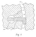
- an under-vane chamber 68 is connected by channel 70 to a fluid flow chamber 72 bordered by the surface of the rotor 14, the cam block inner surface 22, and the vane depicted in FIG. 4 and an adjacent trailing vane (not shown).
- the channel 70 can promote steady under-vane pressure as same as the overvane trailing edge pressure regardless of the vane position in the inlet and discharge ports or in pump arc and the seal arc as shown in FIG 3A surfaces 33 and 68 or FIG 3B surfaces 33 and 60.
Landscapes
- Engineering & Computer Science (AREA)
- Mechanical Engineering (AREA)
- General Engineering & Computer Science (AREA)
- Rotary Pumps (AREA)
Abstract
Description
- This disclosure relates to vane pumps. Vane pumps include different varieties such as single acting or double acting and can be fixed or variable displacement. This disclosure is applicable to all types of vane pumps.
- A typical double-acting
vane pump 10 is depicted inFIG. 1 . The vane pump includes a plurality ofvanes 12 supported in slots in arotor 14. Ashaft 16 supported concentrically within acam block 18 rotates the rotor in the direction ofarrow 20. Thevanes 12 haveradial portions 15 andtip portions 17, and are driven outward from the rotor into contact or engagement with aninner surface 22 of thecam block 18. During operation,shaft 16 rotates within thecam block 18 to move each of thevanes 12 about the circumference of theinner surface 22 of thecam block 18. The contour of the cam blockinner surface 22 creates radial movement of each of thevanes 12, with thevanes 12 moving into and out of the slots in therotor 14 as they follow the contour of the cam blockinner surface 22 - As the vanes move through the
inlet regions 24, a quantity of fluid is trapped within a fluid flow chamber defined between thevanes 12 in the direction of rotation and betweenrotor 14 and the cam blockinner surface 22 in the direction the radial direction. The volume of this chamber begins at an initial size that is progressively increased as the vane transitions frominlet region 24 to pumparc 26. In thepump arc 26 thevane 12 extends a constant amount from therotor 14. As thevane 12 transitions from thepump arc 26 to thedischarge region 30, the radial distance between therotor 14 and the cam blockinner surface 22 is gradually decreased. The decrease in volume of the fluid flow chamber coincides with removal of fluid from the flow chamber through the pump discharge. The discharge pressure is dependent upon the resistance of the downstream system - The vanes rotate through
pump arcs 26 where high pressure is exerted on the leading surface of the vane and low pressure is exerted on the trailing surface, and throughseal arcs 28 where low pressure is exerted on the leading surface of the vane and high pressure is exerted on the trailing surface of the vane. In theinlet regions 24, inlet fluid pressure is provided to support the vanes so that the vanes are radially pressure balanced. In thedischarge regions 30, discharge fluid pressure is provided to support the vanes so that the vanes are also radially pressure balanced in the discharge regions. - In the pump arc and the seal arc, pressure has often been required under the vanes to maintain a seal between the vane tip and the cam block inner surface. Such under-vane pressure can combine with pressure in the fluid flow chamber to result in excess radial pressure load and outward centrifugal force pushing the vane against the cam inner surface. This can result in high adhesive wear stresses between the vane tips and the inner surface of the cam block resulting in damage to the vane and to the cam block. However, prior attempts to remove or reduce under-vane pressurization have often resulted in inadequate outward radial load during low speed operation such as at startup, when centrifugal forces are insufficient to drive the vanes radially outward into engagement with the cam block surface.
-
US Patent No. 7,637,724 discloses a vane pump where avane tip 31 has a radius centered on a centerline offset relative to a leading surface of the vane. This offset provides an imbalance of the fluid pressure forces acting radially on the vane tip to generate a positive contact force that in the pump arc that can supplement the centrifugal force at low operating speeds to reduce or eliminate the need for under-vane pressurization in the pump arc. This is depicted inFIG. 2A , where low (inlet) pressure acts onvane surfaces vane surfaces offset 41 between acenterline 42 of theradial tip 17 and a leadingvane surface 44 provides a surface area differential betweensurfaces larger surface 40 and thesmaller surface 36 results in a net outward radial load urging the vane into engagement with the cam blockinner surface 22. In theseal arcs 26, however, as depicted inFIG. 2B , thelarger surface area 40 under thevane tip 31 is not subjected to fluid pressure with the vane in the retracted position. Low (inlet) pressure acts onsurfaces surfaces surface 53. In theseal arcs 26, theoffset 41 now provides a surface area differential of the surfaces subjected to high pressure, between the larger area ofsurface 50 and the smaller area of under-vane surface 33, resulting in a net radial load inward when the surfaces are subjected to fluid pressure. This necessitates the provision of additional pressurization under the vane in the seal arc, which adds complexity, cost, and weight, in addition to subjecting the under-vane cavities to pressure pulsations. - In some aspects of the disclosure, a vane pump comprises a housing including an inlet and an outlet. A cam block is disposed in the housing, and has a continuous inner surface including a pump arc and a seal arc. A rotor is configured to rotate within the cam block, and includes a plurality of radial slots. A plurality of radially-extendable vanes are disposed in the slots and configured to radially extend from the slots as they rotate past the cam block pump arc. The vanes retract as they rotate past the cam block seal arc. Each of the vanes comprises a radial portion in one of the radial slots and a tip portion extending transverse to the radial portion in a direction of rotation of the rotor. The tip portion has an arcuate surface that engages with the cam block inner surface to provide a fluid seal point along the arcuate surface. Each of the plurality of vanes and radial slots are configured to provide a gap between the vane and the radial slot such that the vane has a different angular position relative to the direction of rotation in a radially extended position compared to an angular position in a radially-retracted position. The different angular positions provide different orientation of the arcuate surface of the vane tip portion with respect to the cam body inner surface, thus providing different fluid stop points on the vane tip portion arcuate surface.
- The subject matter which is regarded as the present disclosure is particularly pointed out and distinctly claimed in the claims at the conclusion of the specification. The foregoing and other features, and advantages of the present disclosure are apparent from the following detailed description taken in conjunction with the accompanying drawings in which:
-
FIG. 1 is a schematic depiction of a typical balancing vane pump; -
FIGS. 2A and 2B schematically depict a vane configuration having a tip portion offset to enhance the distribution of radial forces on the vanes; -
FIGS. 3A and 3B schematically depict a vane configuration; and -
FIG. 4 is a schematic depiction of a vane configuration. - Referring to
FIGS. 3A and 3B , a vane configuration is depicted having a gap between the vane and the radial slot as described herein. The vane inFIGS. 3A and 3B differs from that ofFIGS. 2A and 2B in that it does not require theFIG. 2 offset 41 to provide outward radial load on the vanes in the pump arcs.FIG. 2 depicts anoffset 41 where acenterline 42 of theradial tip 17 is offset from the leadingvane surface 44 toward the direction of rotation to provide the pressure and surface area differential for outward radial load in the pump arcs. It should be noted here that the term "centerline" as used herein refers to an imaginary line extending from the center of the arcuate surface of the radial tip to the arc center point (i.e., the center of an imaginary circle of which the vane tip arcuate surface is a part). The vane inFIG. 3 has anoffset 55 where the offset from the leadingvane surface 44 is away from the direction of rotation instead of toward the direction of rotation. The offset 55 (which can be referred to as a negative offset, with theoffset 41 ofFIG. 2 referred to as a positive offset) can be configured to provide balanced or biased radial loads during operation in the seal arc as described in more detail below. However, this disclosure can also be used to provide variable seal point configurations for vane designs having different zero offsets, or even with positive offsets such asoffset 41 ofFIG. 2 . The disclosure can also be used to provide variable seal point configurations for straight vanes, as well as for balanced vane configurations such as those depicted inFIGS. 1-4 . - As shown in
FIG. 3B , during operation in the seal arc, tangential pressure differences provided by high fluid pressure acting onsurface 52 urges the vane against the leading slot edge 56 (FIG. 3B ). The offset 55 provides a surface area differential between thesurfaces surfaces surfaces surface 53. During operation in the seal arc, fluid pressure acting on thelarger surface 33 and thesmaller surface 60 can result in a net outward radial load urging the vane into engagement with the cam blockinner surface 22. As mentioned above, however, a negative offset is not required and embodiments are contemplated where a zero offset is utilized to provide balanced radially-acting pressure, or a positive offset similar to or smaller in magnitude than the positive offset depicted inFIG. 2A . -
FIG. 3A depicts the vane in operation in the pump arc. The vane slot is defined by leadingslot edge 56 and trailingslot edge 58. The extended vane is shown by a dashed line in a forward position in the slot for illustration and comparison. During operation in the pump arc of the vane pump (FIG. 3B ), high (discharge pressure acts on vane surfaces 40, 64, and 66, and low (inlet) pressure acts onsurfaces surface 64 urges the vane against the trailingslot edge 58 so that the vane moves into the position represented inFIG. 3A by the solid line. This tipping movement of the vane re-positions the point of engagement between the arcuate surface ofvane tip 17 and cam body inner surface 22 (i.e., fluid stop point 59) forward (in the direction of rotation) along the arcuate surface of the vane tip compared to a position of the fluid stop point at or near thecenterline 57 when the vane is in a forward position in the slot such as during operation in the seal arc (FIG. 3B ). This forward repositioning of the fluid stop point on the arcuate surface of thevane tip 17 provides for a relativelysmaller surface 66 exposed to high fluid pressure compared to thesurface 40. During operation in the pump arc, fluid pressure acting on thelarger surface 40 and thesmaller surface 66 can result in a net outward radial load urging the vane into engagement with the cam blockinner surface 22. - The gap between the radial portion of the
vane 15 and the slot inFIGS. 3A and 3B is provided by angling the trailingslot edge 58 away from the direction of rotation. Of course, the configuration represented byFIGS. 3A and 3B is only one example of a configuration that can provide such a gap, and variations can be made to either or both of the slot shape, dimensions, and configuration, and the vane radial portion shape, dimensions, and configuration. For example,FIGS. 3A and 3B depict a trailingslot edge 58 that is at a fixed angle with respect to the leadingslot edge 56. However, the angle can be varied depending on radial distance from the axis of rotation, or the gap can be provided by an angled surface on the leadingslot edge 58 or on the leading or trailing surfaces of thevane radial portion 15. In some embodiments, a fixed angle between the leadingslot edge 56 and the trailingslot edge 58 can vary from 0.1° to 2.0°, depending on the cam profile maximum and minimum radius, so called the vane stroke, and vane tip radius. However, a fixed angle is not required, and the gap between the slot and the vane can be provided by irregular shaped configurations such as step recesses. - The shape and configuration of the arcuate surface of
vane tip 17 can be designed based on parameters such as the radius of cam surfaces, length of theradial vane portion 15, length of extension of the vane out of the slot, and angle of rotation of the van within the slot, to control the location of the fluid stop position along the arcuate surface of thevane tip 17 and to provide desired levels of radial load urging thevane 12 into engagement with the cam blockinner surface 22. The arcuate surface of thevane tip 17 should be configured to have a greater angle of curvature (e.g., smaller radius of curvature) at the point of engagement with the cam block inner surface, and to provide the desired repositioning of the point of engagement along the arcuate surface of thevane tip 17 in response to tipping of the vane. The vane and slot can be configured to provide an angular rotational range of the vane of 0.1° to 2.0° in the slot in the extended position, more specifically from 0.3° to 1.5°. The vane and slot can be configured to provide an angular rotational range of 0.1° to 2.0° in the extended position, more specifically from 0.0° to 1.5°. - The capability of angularly re-positioning the vanes of a vane pump at different cycles of the pump's rotation allows for an offset in the direction of rotation between a fluid stop point where the vane engages the cam block inner surface in the pump arc compared to a leading surface of the vane's radial portion, while also allowing for a zero or negative offset in the seal arc, so that a desired level of radial load can be maintained on the vanes throughout the pump's rotational cycle to maintain a desired level of engagement of the vane with the cam block inner surface. This can avoid the need for complex under-vane pressurization schemes to supplement outward centrifugal force that can be insufficient at low pump speeds such as during startup.
- As mentioned above, under-vane pressurization can contribute to under-vane pressure pulsations, which can cause vane tip wear quickly, cavitation, control valve pressure droop, and the avoidance of such under-vane pressurization can help avoid pressure pulsations. Pressure pulsations can be further reduced by a channel to equalize pressure under the vane and the fluid flow chamber area trailing the vane. As shown in
FIG. 4 , an under-vane chamber 68 is connected bychannel 70 to afluid flow chamber 72 bordered by the surface of therotor 14, the cam blockinner surface 22, and the vane depicted inFIG. 4 and an adjacent trailing vane (not shown). Thechannel 70 can promote steady under-vane pressure as same as the overvane trailing edge pressure regardless of the vane position in the inlet and discharge ports or in pump arc and the seal arc as shown inFIG 3A surfaces 33 and 68 orFIG 3B surfaces 33 and 60.
Claims (14)
- A vane pump, comprising
a housing including an inlet port and an outlet port;
a cam block having a continuous inner surface including a pump arc and a seal arc;
a rotor configured to rotate within the cam block, said rotor including a plurality of radial slots;
a plurality of radially-extendable vanes that radially extend from the slots as they rotate past the cam block pump arc and retract as they rotate past the cam block seal arc, each of the vanes comprising a radial portion in one of the radial slots and a tip portion extending transverse to the radial portion in a direction of rotation of the rotor, said tip portion including an arcuate surface that engages with the cam block inner surface to provide a fluid seal point along the arcuate surface;
wherein each of the plurality of vanes and radial slots are configured to provide a gap between the vane and the radial slot such that the vane has a different angular position relative to the direction of rotation in a radially extended position compared to a radially-retracted position, thereby providing different fluid stop points on the vane tip portion arcuate surface. - The vane pump of claim 1, wherein the fluid seal point of the vane in the radially extended position is offset in the direction of rotation relative to a leading surface of the vane radial portion.
- The vane pump of claim 1, wherein the fluid seal point of the vane in the radially retracted position is not offset with respect to the direction of rotation relative to a leading surface of the vane radial portion.
- The vane pump of claim 1, wherein the fluid seal point of the vane in the radially retracted position is offset away from the direction of rotation relative to a leading surface of the vane radial portion.
- The vane pump of claim 1, wherein the arcuate surface of the vane tip portion has a center line that is offset in the direction of rotation relative to a leading surface of the vane radial portion.
- The vane pump of claim 1, wherein the arcuate surface of the vane tip portion has a center line that is not offset with respect to the direction of rotation relative to a leading surface of the vane radial portion.
- The vane pump of claim 1, wherein the arcuate surface of the vane tip portion has a center line that is offset away from the direction of rotation relative to a leading surface of the vane radial portion.
- The vane pump of any of claims 1-7, wherein the vane has a rotational angular range of motion in the slot in a fully extended position of 0.1° to 2.0°.
- The vane pump of any of claims 1-8, wherein the gap between the vane and the radial slot is an angular gap having a fixed angle.
- The vane pump of claim 9, wherein the angular gap has an angle in the direction of rotation of 0.1° to 2°.
- The vane pump of any of claims 1-10, wherein the radial slot has a leading edge along a plane coincident with an axis of rotation of the rotor, and a trailing edge disposed at a fixed angle to the leading edge.
- The vane pump of claim 11, wherein the fixed angle is from 0.1° to 2.0°.
- The vane pump of any of claims 1-13, further comprising a vent connecting a cavity under the vane to a surface of the rotor on a trailing side of the vane.
- The vane pump of any of claims 1-13, wherein the vane pump does not include under-vane pressurization.
Applications Claiming Priority (1)
| Application Number | Priority Date | Filing Date | Title |
|---|---|---|---|
| US14/804,969 US10047606B2 (en) | 2015-07-21 | 2015-07-21 | Vane pump |
Publications (2)
| Publication Number | Publication Date |
|---|---|
| EP3121370A1 true EP3121370A1 (en) | 2017-01-25 |
| EP3121370B1 EP3121370B1 (en) | 2021-04-07 |
Family
ID=56507488
Family Applications (1)
| Application Number | Title | Priority Date | Filing Date |
|---|---|---|---|
| EP16180630.2A Active EP3121370B1 (en) | 2015-07-21 | 2016-07-21 | Vane pump |
Country Status (2)
| Country | Link |
|---|---|
| US (1) | US10047606B2 (en) |
| EP (1) | EP3121370B1 (en) |
Cited By (2)
| Publication number | Priority date | Publication date | Assignee | Title |
|---|---|---|---|---|
| CN108894911A (en) * | 2018-07-13 | 2018-11-27 | 哈尔滨理工大学 | A kind of primary and secondary blade construction of hydraulic motor |
| CN113027751A (en) * | 2021-03-25 | 2021-06-25 | 宁波圣龙智能汽车系统有限公司 | Single-action oil trapping-free vane pump |
Citations (3)
| Publication number | Priority date | Publication date | Assignee | Title |
|---|---|---|---|---|
| US3869231A (en) * | 1973-10-03 | 1975-03-04 | Abex Corp | Vane type fluid energy translating device |
| US7637724B2 (en) | 2004-08-19 | 2009-12-29 | Hamilton Sundstrand Corporation | Variable displacement vane pump with pressure balanced vane |
| US20140271310A1 (en) * | 2013-03-14 | 2014-09-18 | Woodward, Inc. | Clubhead Vane Pump With Balanced Vanes |
Family Cites Families (8)
| Publication number | Priority date | Publication date | Assignee | Title |
|---|---|---|---|---|
| US3221665A (en) | 1962-01-11 | 1965-12-07 | Hartmann Mfg Co | Hydraulic pump or motor with hydraulic pressure-responsive vane |
| SE384396B (en) * | 1974-03-08 | 1976-05-03 | Atlas Copco Ab | PNEUMATIC SLOW MOTOR |
| US3981648A (en) * | 1974-10-23 | 1976-09-21 | Sperry Rand Corporation | Power transmission |
| JPS5536967U (en) | 1978-08-31 | 1980-03-10 | ||
| US5163825A (en) * | 1991-04-03 | 1992-11-17 | Oetting Roy E | Articulated vane fluid driven motor |
| US5733109A (en) * | 1995-07-12 | 1998-03-31 | Coltec Industries Inc. | Variable displacement vane pump with regulated vane loading |
| US8360759B2 (en) * | 2005-03-09 | 2013-01-29 | Pekrul Merton W | Rotary engine flow conduit apparatus and method of operation therefor |
| EP2126314B1 (en) * | 2005-09-29 | 2019-07-17 | Prime Mover International, LLC | Hydrogen g-cycle rotary internal combustion engine |
-
2015
- 2015-07-21 US US14/804,969 patent/US10047606B2/en active Active
-
2016
- 2016-07-21 EP EP16180630.2A patent/EP3121370B1/en active Active
Patent Citations (3)
| Publication number | Priority date | Publication date | Assignee | Title |
|---|---|---|---|---|
| US3869231A (en) * | 1973-10-03 | 1975-03-04 | Abex Corp | Vane type fluid energy translating device |
| US7637724B2 (en) | 2004-08-19 | 2009-12-29 | Hamilton Sundstrand Corporation | Variable displacement vane pump with pressure balanced vane |
| US20140271310A1 (en) * | 2013-03-14 | 2014-09-18 | Woodward, Inc. | Clubhead Vane Pump With Balanced Vanes |
Cited By (3)
| Publication number | Priority date | Publication date | Assignee | Title |
|---|---|---|---|---|
| CN108894911A (en) * | 2018-07-13 | 2018-11-27 | 哈尔滨理工大学 | A kind of primary and secondary blade construction of hydraulic motor |
| CN113027751A (en) * | 2021-03-25 | 2021-06-25 | 宁波圣龙智能汽车系统有限公司 | Single-action oil trapping-free vane pump |
| CN113027751B (en) * | 2021-03-25 | 2024-09-27 | 宁波圣龙智能汽车系统有限公司 | Single-acting oil-trapping-free vane pump |
Also Published As
| Publication number | Publication date |
|---|---|
| US10047606B2 (en) | 2018-08-14 |
| US20170022813A1 (en) | 2017-01-26 |
| EP3121370B1 (en) | 2021-04-07 |
Similar Documents
| Publication | Publication Date | Title |
|---|---|---|
| JP5060737B2 (en) | Centrifugal pump and its impeller | |
| EP2828525B1 (en) | Variable displacement rotary pump and displacement regulation method | |
| US10724538B2 (en) | Centrifugal compressor | |
| EP3276178B1 (en) | Volute pump | |
| US20140271310A1 (en) | Clubhead Vane Pump With Balanced Vanes | |
| EP3027908B1 (en) | Variable lubricant vane pump | |
| EA028485B1 (en) | Centrifugal machine | |
| EP3121370B1 (en) | Vane pump | |
| US20090274547A1 (en) | Rotating unit for an axial-flow compressor | |
| EP3401550B1 (en) | Volute casing for a centrifugal pump and centrifugal pump | |
| RU2394173C2 (en) | Radial flow pump impeller and radial pump with such impeller | |
| KR20170044004A (en) | Pump for conveying a highly viscous fluid | |
| EP3096022A1 (en) | Impeller and rotating machine provided with same | |
| US9441626B2 (en) | Oval chamber vane pump | |
| CN111556928A (en) | Flow optimized vane pump | |
| EP3056737B1 (en) | Vane pump | |
| NL2013367B1 (en) | Impeller blade with asymmetric thickness. | |
| KR20170044003A (en) | Pump for conveying a highly viscous fluid | |
| CA2839472C (en) | Improvements to pumps and components therefor | |
| WO2014138870A1 (en) | Oval chamber vane pump | |
| CN114483646A (en) | Impeller of rotary machine and rotary machine | |
| CN107939677A (en) | A kind of liquid rotary pump | |
| CN108361192B (en) | Vane pump | |
| RU2451839C1 (en) | Axial-radial tunnel blade wheel | |
| JP2002048083A (en) | Multi-stage slurry pump |
Legal Events
| Date | Code | Title | Description |
|---|---|---|---|
| PUAI | Public reference made under article 153(3) epc to a published international application that has entered the european phase |
Free format text: ORIGINAL CODE: 0009012 |
|
| STAA | Information on the status of an ep patent application or granted ep patent |
Free format text: STATUS: THE APPLICATION HAS BEEN PUBLISHED |
|
| AK | Designated contracting states |
Kind code of ref document: A1 Designated state(s): AL AT BE BG CH CY CZ DE DK EE ES FI FR GB GR HR HU IE IS IT LI LT LU LV MC MK MT NL NO PL PT RO RS SE SI SK SM TR |
|
| AX | Request for extension of the european patent |
Extension state: BA ME |
|
| STAA | Information on the status of an ep patent application or granted ep patent |
Free format text: STATUS: REQUEST FOR EXAMINATION WAS MADE |
|
| 17P | Request for examination filed |
Effective date: 20170725 |
|
| RBV | Designated contracting states (corrected) |
Designated state(s): AL AT BE BG CH CY CZ DE DK EE ES FI FR GB GR HR HU IE IS IT LI LT LU LV MC MK MT NL NO PL PT RO RS SE SI SK SM TR |
|
| GRAP | Despatch of communication of intention to grant a patent |
Free format text: ORIGINAL CODE: EPIDOSNIGR1 |
|
| STAA | Information on the status of an ep patent application or granted ep patent |
Free format text: STATUS: GRANT OF PATENT IS INTENDED |
|
| INTG | Intention to grant announced |
Effective date: 20201110 |
|
| GRAS | Grant fee paid |
Free format text: ORIGINAL CODE: EPIDOSNIGR3 |
|
| GRAA | (expected) grant |
Free format text: ORIGINAL CODE: 0009210 |
|
| STAA | Information on the status of an ep patent application or granted ep patent |
Free format text: STATUS: THE PATENT HAS BEEN GRANTED |
|
| AK | Designated contracting states |
Kind code of ref document: B1 Designated state(s): AL AT BE BG CH CY CZ DE DK EE ES FI FR GB GR HR HU IE IS IT LI LT LU LV MC MK MT NL NO PL PT RO RS SE SI SK SM TR |
|
| REG | Reference to a national code |
Ref country code: GB Ref legal event code: FG4D |
|
| REG | Reference to a national code |
Ref country code: AT Ref legal event code: REF Ref document number: 1379924 Country of ref document: AT Kind code of ref document: T Effective date: 20210415 Ref country code: CH Ref legal event code: EP |
|
| REG | Reference to a national code |
Ref country code: DE Ref legal event code: R096 Ref document number: 602016055534 Country of ref document: DE |
|
| REG | Reference to a national code |
Ref country code: IE Ref legal event code: FG4D |
|
| REG | Reference to a national code |
Ref country code: LT Ref legal event code: MG9D |
|
| REG | Reference to a national code |
Ref country code: NL Ref legal event code: MP Effective date: 20210407 Ref country code: AT Ref legal event code: MK05 Ref document number: 1379924 Country of ref document: AT Kind code of ref document: T Effective date: 20210407 |
|
| PG25 | Lapsed in a contracting state [announced via postgrant information from national office to epo] |
Ref country code: NL Free format text: LAPSE BECAUSE OF FAILURE TO SUBMIT A TRANSLATION OF THE DESCRIPTION OR TO PAY THE FEE WITHIN THE PRESCRIBED TIME-LIMIT Effective date: 20210407 Ref country code: LT Free format text: LAPSE BECAUSE OF FAILURE TO SUBMIT A TRANSLATION OF THE DESCRIPTION OR TO PAY THE FEE WITHIN THE PRESCRIBED TIME-LIMIT Effective date: 20210407 Ref country code: FI Free format text: LAPSE BECAUSE OF FAILURE TO SUBMIT A TRANSLATION OF THE DESCRIPTION OR TO PAY THE FEE WITHIN THE PRESCRIBED TIME-LIMIT Effective date: 20210407 Ref country code: HR Free format text: LAPSE BECAUSE OF FAILURE TO SUBMIT A TRANSLATION OF THE DESCRIPTION OR TO PAY THE FEE WITHIN THE PRESCRIBED TIME-LIMIT Effective date: 20210407 Ref country code: AT Free format text: LAPSE BECAUSE OF FAILURE TO SUBMIT A TRANSLATION OF THE DESCRIPTION OR TO PAY THE FEE WITHIN THE PRESCRIBED TIME-LIMIT Effective date: 20210407 Ref country code: BG Free format text: LAPSE BECAUSE OF FAILURE TO SUBMIT A TRANSLATION OF THE DESCRIPTION OR TO PAY THE FEE WITHIN THE PRESCRIBED TIME-LIMIT Effective date: 20210707 |
|
| PG25 | Lapsed in a contracting state [announced via postgrant information from national office to epo] |
Ref country code: LV Free format text: LAPSE BECAUSE OF FAILURE TO SUBMIT A TRANSLATION OF THE DESCRIPTION OR TO PAY THE FEE WITHIN THE PRESCRIBED TIME-LIMIT Effective date: 20210407 Ref country code: GR Free format text: LAPSE BECAUSE OF FAILURE TO SUBMIT A TRANSLATION OF THE DESCRIPTION OR TO PAY THE FEE WITHIN THE PRESCRIBED TIME-LIMIT Effective date: 20210708 Ref country code: IS Free format text: LAPSE BECAUSE OF FAILURE TO SUBMIT A TRANSLATION OF THE DESCRIPTION OR TO PAY THE FEE WITHIN THE PRESCRIBED TIME-LIMIT Effective date: 20210807 Ref country code: NO Free format text: LAPSE BECAUSE OF FAILURE TO SUBMIT A TRANSLATION OF THE DESCRIPTION OR TO PAY THE FEE WITHIN THE PRESCRIBED TIME-LIMIT Effective date: 20210707 Ref country code: PL Free format text: LAPSE BECAUSE OF FAILURE TO SUBMIT A TRANSLATION OF THE DESCRIPTION OR TO PAY THE FEE WITHIN THE PRESCRIBED TIME-LIMIT Effective date: 20210407 Ref country code: PT Free format text: LAPSE BECAUSE OF FAILURE TO SUBMIT A TRANSLATION OF THE DESCRIPTION OR TO PAY THE FEE WITHIN THE PRESCRIBED TIME-LIMIT Effective date: 20210809 Ref country code: ES Free format text: LAPSE BECAUSE OF FAILURE TO SUBMIT A TRANSLATION OF THE DESCRIPTION OR TO PAY THE FEE WITHIN THE PRESCRIBED TIME-LIMIT Effective date: 20210407 Ref country code: SE Free format text: LAPSE BECAUSE OF FAILURE TO SUBMIT A TRANSLATION OF THE DESCRIPTION OR TO PAY THE FEE WITHIN THE PRESCRIBED TIME-LIMIT Effective date: 20210407 Ref country code: RS Free format text: LAPSE BECAUSE OF FAILURE TO SUBMIT A TRANSLATION OF THE DESCRIPTION OR TO PAY THE FEE WITHIN THE PRESCRIBED TIME-LIMIT Effective date: 20210407 |
|
| REG | Reference to a national code |
Ref country code: DE Ref legal event code: R097 Ref document number: 602016055534 Country of ref document: DE |
|
| PG25 | Lapsed in a contracting state [announced via postgrant information from national office to epo] |
Ref country code: RO Free format text: LAPSE BECAUSE OF FAILURE TO SUBMIT A TRANSLATION OF THE DESCRIPTION OR TO PAY THE FEE WITHIN THE PRESCRIBED TIME-LIMIT Effective date: 20210407 Ref country code: SK Free format text: LAPSE BECAUSE OF FAILURE TO SUBMIT A TRANSLATION OF THE DESCRIPTION OR TO PAY THE FEE WITHIN THE PRESCRIBED TIME-LIMIT Effective date: 20210407 Ref country code: SM Free format text: LAPSE BECAUSE OF FAILURE TO SUBMIT A TRANSLATION OF THE DESCRIPTION OR TO PAY THE FEE WITHIN THE PRESCRIBED TIME-LIMIT Effective date: 20210407 Ref country code: EE Free format text: LAPSE BECAUSE OF FAILURE TO SUBMIT A TRANSLATION OF THE DESCRIPTION OR TO PAY THE FEE WITHIN THE PRESCRIBED TIME-LIMIT Effective date: 20210407 Ref country code: DK Free format text: LAPSE BECAUSE OF FAILURE TO SUBMIT A TRANSLATION OF THE DESCRIPTION OR TO PAY THE FEE WITHIN THE PRESCRIBED TIME-LIMIT Effective date: 20210407 Ref country code: CZ Free format text: LAPSE BECAUSE OF FAILURE TO SUBMIT A TRANSLATION OF THE DESCRIPTION OR TO PAY THE FEE WITHIN THE PRESCRIBED TIME-LIMIT Effective date: 20210407 |
|
| PLBE | No opposition filed within time limit |
Free format text: ORIGINAL CODE: 0009261 |
|
| STAA | Information on the status of an ep patent application or granted ep patent |
Free format text: STATUS: NO OPPOSITION FILED WITHIN TIME LIMIT |
|
| REG | Reference to a national code |
Ref country code: CH Ref legal event code: PL |
|
| 26N | No opposition filed |
Effective date: 20220110 |
|
| PG25 | Lapsed in a contracting state [announced via postgrant information from national office to epo] |
Ref country code: MC Free format text: LAPSE BECAUSE OF FAILURE TO SUBMIT A TRANSLATION OF THE DESCRIPTION OR TO PAY THE FEE WITHIN THE PRESCRIBED TIME-LIMIT Effective date: 20210407 |
|
| REG | Reference to a national code |
Ref country code: BE Ref legal event code: MM Effective date: 20210731 |
|
| PG25 | Lapsed in a contracting state [announced via postgrant information from national office to epo] |
Ref country code: LI Free format text: LAPSE BECAUSE OF NON-PAYMENT OF DUE FEES Effective date: 20210731 Ref country code: CH Free format text: LAPSE BECAUSE OF NON-PAYMENT OF DUE FEES Effective date: 20210731 |
|
| PG25 | Lapsed in a contracting state [announced via postgrant information from national office to epo] |
Ref country code: IS Free format text: LAPSE BECAUSE OF FAILURE TO SUBMIT A TRANSLATION OF THE DESCRIPTION OR TO PAY THE FEE WITHIN THE PRESCRIBED TIME-LIMIT Effective date: 20210807 Ref country code: LU Free format text: LAPSE BECAUSE OF NON-PAYMENT OF DUE FEES Effective date: 20210721 Ref country code: AL Free format text: LAPSE BECAUSE OF FAILURE TO SUBMIT A TRANSLATION OF THE DESCRIPTION OR TO PAY THE FEE WITHIN THE PRESCRIBED TIME-LIMIT Effective date: 20210407 |
|
| PG25 | Lapsed in a contracting state [announced via postgrant information from national office to epo] |
Ref country code: IT Free format text: LAPSE BECAUSE OF FAILURE TO SUBMIT A TRANSLATION OF THE DESCRIPTION OR TO PAY THE FEE WITHIN THE PRESCRIBED TIME-LIMIT Effective date: 20210407 Ref country code: IE Free format text: LAPSE BECAUSE OF NON-PAYMENT OF DUE FEES Effective date: 20210721 Ref country code: BE Free format text: LAPSE BECAUSE OF NON-PAYMENT OF DUE FEES Effective date: 20210731 |
|
| PG25 | Lapsed in a contracting state [announced via postgrant information from national office to epo] |
Ref country code: HU Free format text: LAPSE BECAUSE OF FAILURE TO SUBMIT A TRANSLATION OF THE DESCRIPTION OR TO PAY THE FEE WITHIN THE PRESCRIBED TIME-LIMIT; INVALID AB INITIO Effective date: 20160721 |
|
| P01 | Opt-out of the competence of the unified patent court (upc) registered |
Effective date: 20230522 |
|
| PG25 | Lapsed in a contracting state [announced via postgrant information from national office to epo] |
Ref country code: CY Free format text: LAPSE BECAUSE OF FAILURE TO SUBMIT A TRANSLATION OF THE DESCRIPTION OR TO PAY THE FEE WITHIN THE PRESCRIBED TIME-LIMIT Effective date: 20210407 |
|
| PG25 | Lapsed in a contracting state [announced via postgrant information from national office to epo] |
Ref country code: MK Free format text: LAPSE BECAUSE OF FAILURE TO SUBMIT A TRANSLATION OF THE DESCRIPTION OR TO PAY THE FEE WITHIN THE PRESCRIBED TIME-LIMIT Effective date: 20210407 |
|
| PG25 | Lapsed in a contracting state [announced via postgrant information from national office to epo] |
Ref country code: MT Free format text: LAPSE BECAUSE OF FAILURE TO SUBMIT A TRANSLATION OF THE DESCRIPTION OR TO PAY THE FEE WITHIN THE PRESCRIBED TIME-LIMIT Effective date: 20210407 |
|
| PGFP | Annual fee paid to national office [announced via postgrant information from national office to epo] |
Ref country code: GB Payment date: 20250619 Year of fee payment: 10 |
|
| PGFP | Annual fee paid to national office [announced via postgrant information from national office to epo] |
Ref country code: FR Payment date: 20250620 Year of fee payment: 10 |
|
| PGFP | Annual fee paid to national office [announced via postgrant information from national office to epo] |
Ref country code: DE Payment date: 20250620 Year of fee payment: 10 |
|
| PG25 | Lapsed in a contracting state [announced via postgrant information from national office to epo] |
Ref country code: TR Free format text: LAPSE BECAUSE OF FAILURE TO SUBMIT A TRANSLATION OF THE DESCRIPTION OR TO PAY THE FEE WITHIN THE PRESCRIBED TIME-LIMIT Effective date: 20210407 |