EP3120947A1 - Coiler device provided with chute guide - Google Patents
Coiler device provided with chute guide Download PDFInfo
- Publication number
- EP3120947A1 EP3120947A1 EP15764495.6A EP15764495A EP3120947A1 EP 3120947 A1 EP3120947 A1 EP 3120947A1 EP 15764495 A EP15764495 A EP 15764495A EP 3120947 A1 EP3120947 A1 EP 3120947A1
- Authority
- EP
- European Patent Office
- Prior art keywords
- liner
- metal strip
- body frame
- guide
- coiler device
- Prior art date
- Legal status (The legal status is an assumption and is not a legal conclusion. Google has not performed a legal analysis and makes no representation as to the accuracy of the status listed.)
- Granted
Links
Images




Classifications
-
- B—PERFORMING OPERATIONS; TRANSPORTING
- B21—MECHANICAL METAL-WORKING WITHOUT ESSENTIALLY REMOVING MATERIAL; PUNCHING METAL
- B21C—MANUFACTURE OF METAL SHEETS, WIRE, RODS, TUBES, PROFILES OR LIKE SEMI-MANUFACTURED PRODUCTS OTHERWISE THAN BY ROLLING; AUXILIARY OPERATIONS USED IN CONNECTION WITH METAL-WORKING WITHOUT ESSENTIALLY REMOVING MATERIAL
- B21C47/00—Winding-up, coiling or winding-off metal wire, metal band or other flexible metal material characterised by features relevant to metal processing only
- B21C47/34—Feeding or guiding devices not specially adapted to a particular type of apparatus
- B21C47/3433—Feeding or guiding devices not specially adapted to a particular type of apparatus for guiding the leading end of the material, e.g. from or to a coiler
- B21C47/3441—Diverting the leading end, e.g. from main flow to a coiling device
-
- B—PERFORMING OPERATIONS; TRANSPORTING
- B21—MECHANICAL METAL-WORKING WITHOUT ESSENTIALLY REMOVING MATERIAL; PUNCHING METAL
- B21C—MANUFACTURE OF METAL SHEETS, WIRE, RODS, TUBES, PROFILES OR LIKE SEMI-MANUFACTURED PRODUCTS OTHERWISE THAN BY ROLLING; AUXILIARY OPERATIONS USED IN CONNECTION WITH METAL-WORKING WITHOUT ESSENTIALLY REMOVING MATERIAL
- B21C47/00—Winding-up, coiling or winding-off metal wire, metal band or other flexible metal material characterised by features relevant to metal processing only
- B21C47/02—Winding-up or coiling
- B21C47/04—Winding-up or coiling on or in reels or drums, without using a moving guide
- B21C47/06—Winding-up or coiling on or in reels or drums, without using a moving guide with loaded rollers, bolts, or equivalent means holding the material on the reel or drum
-
- B—PERFORMING OPERATIONS; TRANSPORTING
- B21—MECHANICAL METAL-WORKING WITHOUT ESSENTIALLY REMOVING MATERIAL; PUNCHING METAL
- B21C—MANUFACTURE OF METAL SHEETS, WIRE, RODS, TUBES, PROFILES OR LIKE SEMI-MANUFACTURED PRODUCTS OTHERWISE THAN BY ROLLING; AUXILIARY OPERATIONS USED IN CONNECTION WITH METAL-WORKING WITHOUT ESSENTIALLY REMOVING MATERIAL
- B21C47/00—Winding-up, coiling or winding-off metal wire, metal band or other flexible metal material characterised by features relevant to metal processing only
- B21C47/34—Feeding or guiding devices not specially adapted to a particular type of apparatus
- B21C47/3433—Feeding or guiding devices not specially adapted to a particular type of apparatus for guiding the leading end of the material, e.g. from or to a coiler
-
- B—PERFORMING OPERATIONS; TRANSPORTING
- B21—MECHANICAL METAL-WORKING WITHOUT ESSENTIALLY REMOVING MATERIAL; PUNCHING METAL
- B21B—ROLLING OF METAL
- B21B15/00—Arrangements for performing additional metal-working operations specially combined with or arranged in, or specially adapted for use in connection with, metal-rolling mills
- B21B2015/0057—Coiling the rolled product
Definitions
- the present invention relates to a coiler device provided with a chute guide.
- a coiler device (a winder) is provided on an exit side of a rolling line, and is configured to wind a metal strip (a strip) into a coil shape, where the metal strip is rolled by a rolling mill and continuously supplied from a gap between rollers.
- the coiler device is provided with pinch rollers located on a pass line for the metal strip, and is configured to cause the pinch rollers to guide the metal strip to a winding line which is bent obliquely downward from the pass line, to allow a leading end of the metal strip to be caught by a mandrel, and to wind up the metal strip (see Patent Document 1).
- Patent Document 1 discloses a method and an apparatus for winding a strip, which are designed to wind a rolled strip around a mandrel through pinch rollers.
- the coiler device includes a chute and an over-guide (a chute guide) which introduce a metal strip into a winding port that is formed by the mandrel and a wrapper roller.
- the over-guide is configured to function as a guide plate which guides an upper surface side of the metal strip introduced into the winding line.
- Patent Document 1 Japanese Patent Application Publication No. 2005-305452
- the metal strip is guided to the mandrel while deflecting its passing angle obliquely downward.
- the metal strip is a high-strength thick material
- the metal strip is not bent very much due to its high bending stiffness, and is therefore thrust hard against the chute guide that guides the upper surface side of the metal strip in the winding line.
- a surface of the metal strip is vulnerable to flaws and frictional resistance thereon is increased as well.
- a large pushing force is required and energy consumption is also increased accordingly.
- An object of the present invention is to provide a coiler device provided with a chute guide, which is capable of preventing occurrence of flaws on a surface of a metal strip and stabilizing strip passage even when the metal strip is a high-strength thick material.
- the present invention adopts a configuration of a coiler device provided with a chute guide, characterized by: a pinch roller configured to guide a metal strip being conveyed along a pass line to a winding line bent from the pass line; a mandrel disposed ahead of the winding line and configured to wind up the metal strip; and a chute guide configured to guide an upper surface side of the metal strip in the winding line, and to introduce the metal strip into a winding port of the mandrel.
- the chute guide includes a body frame, and a liner being attached to the body frame, constituting at least part of a guide surface to guide the metal strip, and having a lower friction coefficient than a friction coefficient of the body frame and a lower hardness than a hardness of the metal strip.
- the guide surface is formed from the liner having the lower friction than that of the body frame constituting the chute guide and having the lower hardness than that of the metal strip.
- the presence of the liner can reduce frictional resistance on the guide surface. Accordingly, it is possible to reduce energy consumption since it is not necessary to apply a very large pushing force to the metal strip.
- the liner since the liner has the lower hardness than that of the metal strip, it is the liner which is scraped off when the metal strip is thrust thereon. Thus, a surface of the metal strip is prevented from the occurrence of flaws (from being scraped off).
- the present invention adopts a configuration in which the liner is attached to a downstream side of the body frame in the winding line.
- the downstream side of the chute guide being close to a winding port of the mandrel rubs against the metal strip for a longer period than does the upstream side thereof. Accordingly, by attaching the liner to the downstream side of the body frame, it is possible to effectively prevent an increase in frictional resistance on the guide surface and to prevent the occurrence of flaws on the surface of the metal strip.
- the present invention adopts a configuration in which the coiler device includes an attachment unit configured to detachably attach the liner to the body frame.
- the present invention adopts a configuration in which the attachment unit includes: a frame body provided to the body frame; a slide groove provided in the liner; a slide piece configured to be engaged with the slide groove, and to sandwich the frame body in conjunction with the liner; and a screw member configured to fasten and fix the slide piece to the liner.
- the liner can be detached from the frame body provided to the body frame by releasing fastening and fixation with the screw member and then moving the slide piece along the slide groove of the liner to release engagement with the liner. Accordingly, even if the fastening and fixation by the screw member is released, for instance, the liner remains supported by the body frame unless the engagement of the slide piece with the liner is released. Thus, it is possible to surely avoid a circumstance such as the liner being unexpectedly falling off and getting caught in the metal strip.
- the present invention adopts a configuration in which the slide piece includes an engagement protrusion configured to be engaged with the slide groove, and the slide groove includes a first opening opened with a larger width than a width of the engagement protrusion, and a second opening opened with a smaller width than the width of the engagement protrusion.
- the slide piece and the liner can be easily brought into engagement with each other by introducing the engagement protrusion of the slide piece from the first opening into the slide groove and then causing the engagement protrusion to slide to the second opening.
- the present invention adopts a configuration in which the liner includes a plurality of pieces arranged in a width direction of the winding line, and the plurality of pieces are detachably attached to the body frame independently of each other.
- a coiler device provided with a chute guide, which is capable of preventing occurrence of flaws on a surface of a metal strip and stabilizing strip passage even when the metal strip is a high-strength thick material.
- Fig. 1 is an overall configuration diagram showing a coiler device 1 according to an embodiment of the present invention.
- the coiler device 1 is disposed on a downstream side of a not-illustrated rolling mill, and is configured to introduce a metal strip 2, which passes through the rolling mill and is conveyed along a pass line L1, to a winding line L2 and thereby winding up the metal strip 2.
- the pass line L1 is defined by multiple conveyance rollers 3 that are arranged horizontally.
- the coiler device 1 includes pinch rollers 10a and 10b.
- the pinch rollers 10a and 10b are designed to guide the metal strip 2, which is conveyed along the pass line L1, to the winding line L2 that is bent from the pass line L1.
- the winding line L2 extends obliquely downward from the pass line L1.
- the upper pinch roller 10a is made capable of approaching and receding from the lower pinch roller 10b.
- the upper pinch roller 10a is designed to recede from the lower pinch roller 10b except in the case of winding the metal strip 2 around a mandrel 20 to be described below.
- the coiler device 1 includes the mandrel 20.
- the mandrel 20 is disposed ahead of the winding line L2 and designed to wind up the metal strip 2.
- Multiple wrapper rollers 21 and wrapper aprons 22 are provided around the mandrel 20.
- the wrapper rollers 21 are provided for wrapping the metal strip 2 around the mandrel 20.
- the wrapper rollers 21 are disposed at intervals in a circumferential direction of the mandrel 20.
- the wrapper rollers 21 are made capable of approaching and receding from the mandrel 20.
- the wrapper rollers 21 are designed to move in conformity with a diameter of the metal strip 2 wrapped around the mandrel 20.
- the wrapper aprons 22 are designed to lead a leading end of the metal strip 2 when the metal strip 2 is wrapped around the mandrel 20.
- Each wrapper apron 22 has a guide surface 22a, which is opposed to a peripheral surface of the mandrel 20, and allows the leading end of the metal strip 2 to come into contact therewith.
- the guide surface 22a is curved along the peripheral surface of the mandrel 20.
- Each wrapper apron 22 is disposed in a space between two corresponding wrapper rollers 21 adjacent to each other in the circumferential direction of the mandrel 20.
- the wrapper aprons 22 are made capable of approaching and receding from the mandrel 20.
- the wrapper aprons 22 are designed to recede from the mandrel 20 when the metal strip 2 is wrapped therearound.
- the coiler device 1 includes a gate 30.
- the gate 30 is configured to open and close the winding line L2 ( Fig. 1 shows an open state).
- the gate 30 is disposed on an exit side of the pinch rollers 10a and 10b.
- the gate 30 includes a first guide surface 31 that defines the pass line L1, and a second guide surface 32 that defines the winding line L2.
- the first guide surface 31 is formed into a horizontal surface extending along the pass line L1.
- the second guide surface 32 is formed into an inclined surface extending along the winding line L2.
- the gate 30 has a structure in which a tip end of a substantially V shape is directed to an upstream side of the pass line L1.
- the gate 30 defines the winding line L2 in conjunction with chute guides 40a and 40b.
- the chute guides 40a and 40b are designed to guide the leading end of the metal strip 2 to the winding port 23 between the mandrel 20 and the corresponding wrapper roller 21.
- the chute guides 40a and 40b are arranged in a downward tapered fashion such that a clearance therebetween is gradually narrowed toward the catch part between the mandrel 20 and the wrapper roller 21.
- the chute guides 40a and 40b are disposed on a downstream side of the gate 30 in the winding line L2.
- the lower chute guide 40b is provided integrally with one of the wrapper aprons 22.
- the upper chute guide 40a is provided turnably about a rotating shaft 41.
- the coiler device 1 includes a chute roller 50.
- the chute roller 50 is configured to suppress a deformation of the metal strip 2 in such a way as to be curved toward its upper surface side when the leading end of the metal strip 2 is wrapped around the mandrel 20.
- the chute roller 50 is disposed at a position corresponding to a joint between the gate 30 and the upper chute guide 40a, which is disposed on the downstream side of the gate 30 on the winding line L2.
- the chute roller 50 is rotatably provided and its peripheral surface projects from the second guide surface 32.
- the coiler device 1 includes a bending roller 60.
- the bending roller 60 is disposed on an upstream side of the pinch rollers 10a and 10b, and is made capable of approaching and receding from the pass line L1 by use of a bending roller drive device 61.
- the bending roller 60 is configured to approach the pass line L1 when the rolling of the metal strip 2 is about to finish, so as to prevent its trailing end from bouncing up.
- the bending roller drive device 61 is formed from a cylinder device, for example.
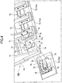
- Fig. 2 is a perspective view of the chute guide 40a according to the embodiment of the present invention, which is viewed from a back side.
- Fig. 3 is a cross-sectional view taken along and viewed in a direction of arrows I-I in Fig. 2 .
- Fig. 4 is an exploded perspective view showing attachment units 73 according to the embodiment of the present invention.
- Fig. 5 is a perspective view showing a liner 72 according to the embodiment of the present invention.
- Fig. 6 is a perspective view showing a slide piece 76 according to the embodiment of the present invention.
- the chute guide 40a is configured to guide the upper surface side of the metal strip 2 introduced into the winding line L2 (see Fig. 1 ), and to introduce the metal strip 2 into the winding port 23 of the mandrel 20.
- the chute guide 40a includes a body frame 70.
- a front side of the body frame 70 forms a guide surface 42 that guides the upper surface side of the metal strip 2.
- multiple reinforcement ribs 71 are provided on a back side of the body frame 70.
- the chute guide 40a includes the liner 72. As shown in Fig. 1 , the liner 72 is attached to the body frame 70, and constitutes at least part of the guide surface 42 that guides the metal strip 2.
- the liner 72 is formed from a low friction material having a lower friction coefficient than that of the body frame 70, which is also a low hardness material having a lower hardness than that of the metal strip 2.
- the liner 72 of this embodiment is made of an FCD (ductile cast iron) material, for example.
- the liner 72 is attached to a downstream side of the body frame 70 in the winding line L2.
- the liner 72 of this embodiment forms a portion of the guide surface 42 that accounts for about one-fifth starting from a downstream end of the body frame 70.
- a downstream end of the liner 72 projects from the downstream end of the body frame 70 and is disposed in proximity to a peripheral surface of the first wrapper roller 21.
- the liner 72 is formed from multiple pieces 72a arranged in a width direction of the winding line L2.
- the liner 72 of this embodiment adopts a configuration including four pieces 72a, so that each of the four pieces 72a is independently replaceable.
- the chute guide 40a includes attachment units 73.
- the attachment units 73 are configured to detachably attach the liner 72 to the body frame 70.
- the attachment units 73 of this embodiment are configured to detachably attach the respective pieces 72a of the liner 72 to the body frame 70 independently of one another (see Fig. 2 and Fig. 4 ).
- Each attachment unit 73 includes a frame body 74, a slide groove 75, slide pieces 76, and screw members 77.
- the frame body 74 is provided to the body frame 70. Specifically, the frame body 74 is provided on the downstream side of the body frame 70 in the winding line L2, and forms an integral structure with the body frame 70. A fitting hole 74a in a convex shape with its leading end directed to the downstream side of the winding line L2 is formed on an inner side of the frame body 74. The fitting hole 74a is formed between the reinforcement ribs 71 that are adjacent to each other.
- the slide groove 75 is provided in the liner 72 as shown in Fig. 4 .
- the liner 72 includes a convex projection 78 to be fitted into the fitting hole 74a of the frame body 74.
- the slide groove 75 is formed in the projection 78.
- Screw holes 79 to be threadedly engaged with the screw members 77 are formed in the projection 78.
- the screw holes 79 are formed at four positions in total, namely, at two positions each while interposing the slide groove 75 in between. As shown in Fig. 3 , the screw holes 79 are formed so as not to penetrate or reach the guide surface 42.
- each slide piece 76 is configured to be engaged with the slide groove 75, and to sandwich the frame body 74 in conjunction with the liner 72.
- this embodiment adopts a configuration in which the two slide pieces 76 are engaged with the single slide groove 75.
- Each slide piece 76 includes an engagement protrusion 80 to be engaged with the slide groove 75.
- the engagement protrusion 80 is formed into a T-shape in a cross-sectional view. Specifically, as shown in Fig. 6 , the engagement protrusion 80 is formed from a head portion 80a having a large width, and a neck portion 80b having a smaller width.
- the slide piece 76 includes insertion holes 81 to allow insertion of the screw members 77, which are formed at two positions in total, namely, at one position each while interposing the engagement protrusion 80 in between.
- the slide groove 75 includes a first opening 82 which is opened at a large width, and second openings 83 which are opened at a small width.
- the first opening 82 enables introduction of the engagement protrusion 80 of the slide piece 76, and is opened at a larger width than a width of the engagement protrusion 80 (the head portion 80a).
- the second openings 83 enable engagement with the engagement protrusion 80 of the slide piece 76, and are opened at a smaller width than the width of the engagement protrusion 80 (the head portion 80a). Note that hooks are fitted into holes 84 shown in Fig. 5 at the time of slinging up the liner 72.
- the first opening 82 is disposed at a central part of the slide groove 75 while the second openings 83 are disposed on two end portions of the slide groove 75.
- Each second opening 83 is configured to reduce an opening width of the slide groove 75 down to the width of the neck portion 80b of the engagement protrusion 80.
- the two end portions of the slide groove 75 are formed into a T-shape in a cross-sectional view so as to correspond to the engagement protrusion 80, thereby enabling the engagement with the slide pieces 76.
- the liner 72 and the slide pieces 76 are formed greater than the fitting hole 74a, so that the frame body 74 can be sandwiched from the front and the back by engaging the liner 72 with the slide pieces 76.
- the screw members 77 are configured to fasten and fix the slide pieces 76 to the liner 72.
- Each screw member 77 passes through the insertion hole 81 and is threadedly engaged with the screw hole 79, thereby preventing disengagement while restricting movement of the slide piece 76 along the slide groove 75, and constricting the frame body 74 between the liner 72 and the slide piece 76 at the same time.
- the screw members 77 fasten and fix the slide piece 76 at the two positions.
- the screw members 77 are connected to each other with wiring 85 so as to keep them from turning and loosening.
- Fig. 7 is a diagram for explaining a winding operation of the coiler device 1 and an action of the chute guide 40a according to the embodiment of the present invention.
- the metal strip 2 having passed through the not-illustrated rolling mill is conveyed along the pass line L1 and reaches the pinch rollers 10a and 10b.
- the metal strip 2 changes its passing angle obliquely downward and is hence guided to the winding line L2 which is bent from the pass line L1.
- the metal strip 2 is the high-strength thick material, its leading end is not bent enormously but is instead curved in such a way as to draw an arc.
- the metal strip 2 is thrust against the chute guide 40a in the winding line L2.
- the chute guide 40a includes the guide surface 42 which guides the upper surface side of the metal strip 2 introduced into the winding line L2. At least part of the guide surface 42 is formed from the liner 72.
- the liner 72 is made of the low friction material having the lower friction coefficient than that of the body frame 70 constituting the chute guide 40a, and thus reduces frictional resistance against the metal strip 2. In this way, by attaching the liner 72 to the body frame 70 and reducing the frictional resistance on the guide surface 42, it is possible to reduce energy consumption since it is not necessary to apply a very large pushing force to the metal strip 2.
- the liner 72 is made of the low hardness material having the lower hardness than that of the metal strip 2, it is the liner 72 which is scraped off when the metal strip 2 is thrust thereon.
- the surface of the metal strip 2 is prevented from the occurrence of flaws (from being scraped off) .
- at least part of the guide surface 42 is formed from the liner 72 having the lower friction than that of the body frame 70 constituting the chute guide 40a and having the lower hardness than that of the metal strip 2.
- the leading end of the metal strip 2 introduced into the winding line L2 is thrust at the body frame 70. Thereafter, the metal strip 2 is thrust at the liner 72 disposed on the downstream side of the winding line L2, then passes through the winding port 23, and is wound around the mandrel 20.
- the metal strip 2 is the high-strength thick material, as the metal strip 2 is wound around the mandrel 20 one time, a downstream side thereof is lifted up by its leading end that gets into a bottom side. Hence, the metal strip 2 will remain thrust at the downstream side of the chute guide 40a for some time while being wound around the mandrel 20.
- the metal strip 2 is thrust on the downstream side of the chute guide 40a for a longer period than is thrust on the upstream side thereof.
- the liner 72 of this embodiment is attached to the downstream side of the body frame 70 in the winding line L2. According to this configuration, it is possible to effectively prevent an increased in frictional resistance on the guide surface 42 on the downstream side, which is close to the winding port 23 of the mandrel 20 and rubs against the metal strip 2 for a long period, and to effectively prevent the occurrence of flaws on the surface of the metal strip 2.
- the liner 72 of this embodiment is detachably attached to the body frame 70 by using the attachment units 73. Accordingly, it is possible to replace only the liner 72, which rubs against the metal strip 2 and gradually wears away, separately from the body frame 70. As a consequence, replacement workability is improved as compared to the case of replacing the liner 72 together with the body frame 70, and a replacement cost can be reduced as well.
- the liner 72 is formed from the multiple pieces 72a arranged in the width direction of the winding line L2, and the multiple pieces 72a are detachably attached to the body frame 70 independently of one another. A weight of each of the pieces 72a is obviously lighter than a total weight of the liner 72, and it is therefore easy to conduct replacement work.
- the liner 72 may be worn unevenly in the width direction.
- the liner 72 is formed from the multiple pieces 72a so as to be replaceable partially in terms of the width direction, thereby allowing the replacement of only the unevenly worn part, for example. As a consequence, it is possible to further reduce the replacement cost for the liner 72.
- the attachment of the liner 72 of this embodiment is conducted as illustrated in Fig. 4 .
- the liner 72 is slung up with a wire and the projection 78 is fitted from a top side of the frame body 74 into the fitting hole 74a.
- the slide pieces 76 are brought into engagement with the slide groove 75 from a back side of the frame body 74.
- the engagement protrusion 80 of each slide piece 76 is introduced from the first opening 82 into the slide groove 75, and is then caused to slide to the second opening 83.
- the slide piece 76 and the liner 72 are engaged with each other.
- the slide pieces 76 are fastened and fixed to the liner 72 by using the screw members 77. In this way, the attachment of the liner 72 is completed.
- the detachment of the liner 72 is conducted in a reverse procedure to the above-described attachment. Specifically, the fastening and fixation by the screw members 77 is released and then the slide pieces 76 are moved along the slide groove 75 of the liner 72 to release the engagement with the liner 72. Thus, the liner 72 can be detached from the frame body 74 provided to the body frame 70.
- the above-described embodiment adopts the configuration of the coiler device 1 provided with the chute guide 40a, including: the pinch rollers 10a and 10b configured to guide the metal strip 2, which is conveyed along the pass line L1, to the winding line L2 bent from the pass line L1; the mandrel 20 disposed ahead of the winding line L2 and configured to wind up the metal strip 2; and the chute guide 40a configured to guide the upper surface side of the metal strip 2 in the winding line L2, and to introduce the metal strip 2 into the winding port 23 of the mandrel 20, in which the chute guide 40a includes the body frame 70, and the liner 72 being attached to the body frame 70, constituting at least part of the guide surface 42 that guides the metal strip 2, and having the lower friction coefficient than that of the body frame 70 and the lower hardness than that of the metal strip 2.
- the coiler device 1 provided with the chute guide 40a which is capable of preventing occurrence of flaws on the surface of the metal strip 2 and stabilizing strip passage
- the present invention may adopt the following aspect shown in Fig. 8 .
- constituents which are identical or similar to those in the above-mentioned embodiment will be denoted by the same reference numerals and the description thereof will be either simplified or omitted.
- Fig. 8 is an overall configuration diagram showing the coiler device 1 according to another embodiment of the present invention.
- the liner 72 of the other embodiment constitutes a downstream end of the chute guide 40a.
- the liner 72 is detachably attached to the body frame 70 by using the attachment units 73 formed from screw members 86.
- This configuration makes it possible to secure a thickness of the liner 72 and to ensure a large scrape margin. Thus, it is possible to reduce the frequency of replacement of the liner 72. It is to be noted, however, that the weight of the liner 72 becomes larger than that in the above-described embodiment.
- the embodiments have described the configuration in which the liner is formed from the multiple pieces.
- the present invention is not limited only to this configuration.
- the liner may be formed from a single piece.
Landscapes
- Engineering & Computer Science (AREA)
- Mechanical Engineering (AREA)
- Winding, Rewinding, Material Storage Devices (AREA)
Abstract
Description
- The present invention relates to a coiler device provided with a chute guide.
- In general, a coiler device (a winder) is provided on an exit side of a rolling line, and is configured to wind a metal strip (a strip) into a coil shape, where the metal strip is rolled by a rolling mill and continuously supplied from a gap between rollers. The coiler device is provided with pinch rollers located on a pass line for the metal strip, and is configured to cause the pinch rollers to guide the metal strip to a winding line which is bent obliquely downward from the pass line, to allow a leading end of the metal strip to be caught by a mandrel, and to wind up the metal strip (see Patent Document 1).
- Patent Document 1 cited below discloses a method and an apparatus for winding a strip, which are designed to wind a rolled strip around a mandrel through pinch rollers. The coiler device includes a chute and an over-guide (a chute guide) which introduce a metal strip into a winding port that is formed by the mandrel and a wrapper roller. The over-guide is configured to function as a guide plate which guides an upper surface side of the metal strip introduced into the winding line.
- Patent Document 1:
Japanese Patent Application Publication No. 2005-305452 - In the meantime, after having passed through the pinch rollers, the metal strip is guided to the mandrel while deflecting its passing angle obliquely downward. Here, if the metal strip is a high-strength thick material, the metal strip is not bent very much due to its high bending stiffness, and is therefore thrust hard against the chute guide that guides the upper surface side of the metal strip in the winding line. As a consequence, a surface of the metal strip is vulnerable to flaws and frictional resistance thereon is increased as well. Hence, a large pushing force is required and energy consumption is also increased accordingly.
- The present invention has been made in view of the above-mentioned problem. An object of the present invention is to provide a coiler device provided with a chute guide, which is capable of preventing occurrence of flaws on a surface of a metal strip and stabilizing strip passage even when the metal strip is a high-strength thick material.
- In order to solve the problem described above, the present invention adopts a configuration of a coiler device provided with a chute guide, characterized by: a pinch roller configured to guide a metal strip being conveyed along a pass line to a winding line bent from the pass line; a mandrel disposed ahead of the winding line and configured to wind up the metal strip; and a chute guide configured to guide an upper surface side of the metal strip in the winding line, and to introduce the metal strip into a winding port of the mandrel. The chute guide includes a body frame, and a liner being attached to the body frame, constituting at least part of a guide surface to guide the metal strip, and having a lower friction coefficient than a friction coefficient of the body frame and a lower hardness than a hardness of the metal strip.
- As a consequence of adopting this configuration, in the present invention, at least part of the guide surface is formed from the liner having the lower friction than that of the body frame constituting the chute guide and having the lower hardness than that of the metal strip. The presence of the liner can reduce frictional resistance on the guide surface. Accordingly, it is possible to reduce energy consumption since it is not necessary to apply a very large pushing force to the metal strip. Moreover, since the liner has the lower hardness than that of the metal strip, it is the liner which is scraped off when the metal strip is thrust thereon. Thus, a surface of the metal strip is prevented from the occurrence of flaws (from being scraped off).
- In addition, the present invention adopts a configuration in which the liner is attached to a downstream side of the body frame in the winding line.
- As a consequence of adopting this configuration, in the present invention, in the winding line, the downstream side of the chute guide being close to a winding port of the mandrel rubs against the metal strip for a longer period than does the upstream side thereof. Accordingly, by attaching the liner to the downstream side of the body frame, it is possible to effectively prevent an increase in frictional resistance on the guide surface and to prevent the occurrence of flaws on the surface of the metal strip.
- In addition, the present invention adopts a configuration in which the coiler device includes an attachment unit configured to detachably attach the liner to the body frame.
- As a consequence of adopting this configuration, in the present invention, it is possible to replace only the liner which rubs against the metal strip and gradually wears away. Thus, replacement workability is improved as compared to a case of replacing the liner together with the body frame, and a replacement cost can be reduced as well.
- In addition, the present invention adopts a configuration in which the attachment unit includes: a frame body provided to the body frame; a slide groove provided in the liner; a slide piece configured to be engaged with the slide groove, and to sandwich the frame body in conjunction with the liner; and a screw member configured to fasten and fix the slide piece to the liner.
- As a consequence of adopting this configuration, in the present invention, the liner can be detached from the frame body provided to the body frame by releasing fastening and fixation with the screw member and then moving the slide piece along the slide groove of the liner to release engagement with the liner. Accordingly, even if the fastening and fixation by the screw member is released, for instance, the liner remains supported by the body frame unless the engagement of the slide piece with the liner is released. Thus, it is possible to surely avoid a circumstance such as the liner being unexpectedly falling off and getting caught in the metal strip.
- In addition, the present invention adopts a configuration in which the slide piece includes an engagement protrusion configured to be engaged with the slide groove, and the slide groove includes a first opening opened with a larger width than a width of the engagement protrusion, and a second opening opened with a smaller width than the width of the engagement protrusion.
- As a consequence of adopting this configuration, in the present invention, the slide piece and the liner can be easily brought into engagement with each other by introducing the engagement protrusion of the slide piece from the first opening into the slide groove and then causing the engagement protrusion to slide to the second opening.
- In addition, the present invention adopts a configuration in which the liner includes a plurality of pieces arranged in a width direction of the winding line, and the plurality of pieces are detachably attached to the body frame independently of each other.
- As a consequence of adopting this configuration, in the present invention, when the metal strip is rolled out of a rolling mill, a shape of a leading end of the metal strip often fails to be aligned straight, and the liner may be worn unevenly in the width direction. Hence, by forming the liner from the multiple pieces so as to be replaceable partially in terms of the width direction, it is possible to further reduce the replacement cost.
- According to the present invention, it is possible to obtain a coiler device provided with a chute guide, which is capable of preventing occurrence of flaws on a surface of a metal strip and stabilizing strip passage even when the metal strip is a high-strength thick material.
-
- [
Fig. 1] Fig. 1 is an overall configuration diagram showing a coiler device according to an embodiment of the present invention. - [
Fig. 2] Fig. 2 is a perspective view of a chute guide according to the embodiment of the present invention, which is viewed from a back side. - [
Fig. 3] Fig. 3 is a cross-sectional view taken along and viewed in a direction of arrows I-I inFig. 2 . - [
Fig. 4] Fig. 4 is an exploded perspective view showing attachment units according to the embodiment of the present invention. - [
Fig. 5] Fig. 5 is a perspective view showing a liner according to the embodiment of the present invention. - [
Fig. 6] Fig. 6 is a perspective view showing a slide piece according to the embodiment of the present invention. - [
Fig. 7] Fig. 7 is a diagram for explaining a winding operation of the coiler device and an action of the chute guide according to the embodiment of the present invention. - [
Fig. 8] Fig. 8 is an overall configuration diagram showing a coiler device according to another embodiment of the present invention. - Embodiments of the present invention will be described below with reference to the drawings.
-
Fig. 1 is an overall configuration diagram showing a coiler device 1 according to an embodiment of the present invention. - As shown in
Fig. 1 , the coiler device 1 is disposed on a downstream side of a not-illustrated rolling mill, and is configured to introduce ametal strip 2, which passes through the rolling mill and is conveyed along a pass line L1, to a winding line L2 and thereby winding up themetal strip 2. The pass line L1 is defined bymultiple conveyance rollers 3 that are arranged horizontally. - The coiler device 1 includes
pinch rollers pinch rollers metal strip 2, which is conveyed along the pass line L1, to the winding line L2 that is bent from the pass line L1. The winding line L2 extends obliquely downward from the pass line L1. Theupper pinch roller 10a is made capable of approaching and receding from thelower pinch roller 10b. Theupper pinch roller 10a is designed to recede from thelower pinch roller 10b except in the case of winding themetal strip 2 around amandrel 20 to be described below. - The coiler device 1 includes the
mandrel 20. Themandrel 20 is disposed ahead of the winding line L2 and designed to wind up themetal strip 2.Multiple wrapper rollers 21 andwrapper aprons 22 are provided around themandrel 20. Thewrapper rollers 21 are provided for wrapping themetal strip 2 around themandrel 20. Thewrapper rollers 21 are disposed at intervals in a circumferential direction of themandrel 20. Thewrapper rollers 21 are made capable of approaching and receding from themandrel 20. Thewrapper rollers 21 are designed to move in conformity with a diameter of themetal strip 2 wrapped around themandrel 20. - The wrapper aprons 22 are designed to lead a leading end of the
metal strip 2 when themetal strip 2 is wrapped around themandrel 20. Eachwrapper apron 22 has aguide surface 22a, which is opposed to a peripheral surface of themandrel 20, and allows the leading end of themetal strip 2 to come into contact therewith. Theguide surface 22a is curved along the peripheral surface of themandrel 20. Eachwrapper apron 22 is disposed in a space between twocorresponding wrapper rollers 21 adjacent to each other in the circumferential direction of themandrel 20. The wrapper aprons 22 are made capable of approaching and receding from themandrel 20. The wrapper aprons 22 are designed to recede from themandrel 20 when themetal strip 2 is wrapped therearound. - The coiler device 1 includes a
gate 30. Thegate 30 is configured to open and close the winding line L2 (Fig. 1 shows an open state). Thegate 30 is disposed on an exit side of thepinch rollers gate 30 includes afirst guide surface 31 that defines the pass line L1, and asecond guide surface 32 that defines the winding line L2. Thefirst guide surface 31 is formed into a horizontal surface extending along the pass line L1. Thesecond guide surface 32 is formed into an inclined surface extending along the winding line L2. Thegate 30 has a structure in which a tip end of a substantially V shape is directed to an upstream side of the pass line L1. - The
gate 30 defines the winding line L2 in conjunction with chute guides 40a and 40b. The chute guides 40a and 40b are designed to guide the leading end of themetal strip 2 to the windingport 23 between themandrel 20 and thecorresponding wrapper roller 21. The chute guides 40a and 40b are arranged in a downward tapered fashion such that a clearance therebetween is gradually narrowed toward the catch part between themandrel 20 and thewrapper roller 21. The chute guides 40a and 40b are disposed on a downstream side of thegate 30 in the winding line L2. In this embodiment, thelower chute guide 40b is provided integrally with one of thewrapper aprons 22. Meanwhile, theupper chute guide 40a is provided turnably about arotating shaft 41. - The coiler device 1 includes a
chute roller 50. Thechute roller 50 is configured to suppress a deformation of themetal strip 2 in such a way as to be curved toward its upper surface side when the leading end of themetal strip 2 is wrapped around themandrel 20. Thechute roller 50 is disposed at a position corresponding to a joint between thegate 30 and theupper chute guide 40a, which is disposed on the downstream side of thegate 30 on the winding line L2. Thechute roller 50 is rotatably provided and its peripheral surface projects from thesecond guide surface 32. - The coiler device 1 includes a bending
roller 60. The bendingroller 60 is disposed on an upstream side of thepinch rollers roller drive device 61. The bendingroller 60 is configured to approach the pass line L1 when the rolling of themetal strip 2 is about to finish, so as to prevent its trailing end from bouncing up. The bendingroller drive device 61 is formed from a cylinder device, for example. - Next, a configuration of the
chute guide 40a will be described in detail while additionally referring toFig. 2 to Fig. 6 .Fig. 2 is a perspective view of thechute guide 40a according to the embodiment of the present invention, which is viewed from a back side.Fig. 3 is a cross-sectional view taken along and viewed in a direction of arrows I-I inFig. 2 .Fig. 4 is an exploded perspective viewshowing attachment units 73 according to the embodiment of the present invention.Fig. 5 is a perspective view showing aliner 72 according to the embodiment of the present invention.Fig. 6 is a perspective view showing aslide piece 76 according to the embodiment of the present invention. - The
chute guide 40a is configured to guide the upper surface side of themetal strip 2 introduced into the winding line L2 (seeFig. 1 ), and to introduce themetal strip 2 into the windingport 23 of themandrel 20. Thechute guide 40a includes abody frame 70. A front side of thebody frame 70 forms aguide surface 42 that guides the upper surface side of themetal strip 2. As shown inFig. 2 ,multiple reinforcement ribs 71 are provided on a back side of thebody frame 70. - The
chute guide 40a includes theliner 72. As shown inFig. 1 , theliner 72 is attached to thebody frame 70, and constitutes at least part of theguide surface 42 that guides themetal strip 2. Theliner 72 is formed from a low friction material having a lower friction coefficient than that of thebody frame 70, which is also a low hardness material having a lower hardness than that of themetal strip 2. Theliner 72 of this embodiment is made of an FCD (ductile cast iron) material, for example. - As shown in
Fig. 1 , theliner 72 is attached to a downstream side of thebody frame 70 in the winding line L2. Theliner 72 of this embodiment forms a portion of theguide surface 42 that accounts for about one-fifth starting from a downstream end of thebody frame 70. A downstream end of theliner 72 projects from the downstream end of thebody frame 70 and is disposed in proximity to a peripheral surface of thefirst wrapper roller 21. Moreover, as shown inFig. 2 , theliner 72 is formed frommultiple pieces 72a arranged in a width direction of the winding line L2. Theliner 72 of this embodiment adopts a configuration including fourpieces 72a, so that each of the fourpieces 72a is independently replaceable. - As shown in
Fig. 3 , thechute guide 40a includesattachment units 73. Theattachment units 73 are configured to detachably attach theliner 72 to thebody frame 70. Theattachment units 73 of this embodiment are configured to detachably attach therespective pieces 72a of theliner 72 to thebody frame 70 independently of one another (seeFig. 2 andFig. 4 ). Eachattachment unit 73 includes aframe body 74, aslide groove 75,slide pieces 76, andscrew members 77. - As shown in
Fig. 4 , theframe body 74 is provided to thebody frame 70. Specifically, theframe body 74 is provided on the downstream side of thebody frame 70 in the winding line L2, and forms an integral structure with thebody frame 70. Afitting hole 74a in a convex shape with its leading end directed to the downstream side of the winding line L2 is formed on an inner side of theframe body 74. Thefitting hole 74a is formed between thereinforcement ribs 71 that are adjacent to each other. - The
slide groove 75 is provided in theliner 72 as shown inFig. 4 . Theliner 72 includes aconvex projection 78 to be fitted into thefitting hole 74a of theframe body 74. Theslide groove 75 is formed in theprojection 78. Screw holes 79 to be threadedly engaged with thescrew members 77 are formed in theprojection 78. The screw holes 79 are formed at four positions in total, namely, at two positions each while interposing theslide groove 75 in between. As shown inFig. 3 , the screw holes 79 are formed so as not to penetrate or reach theguide surface 42. - As shown in
Fig. 3 , eachslide piece 76 is configured to be engaged with theslide groove 75, and to sandwich theframe body 74 in conjunction with theliner 72. As shown inFig. 4 , this embodiment adopts a configuration in which the twoslide pieces 76 are engaged with thesingle slide groove 75. Eachslide piece 76 includes anengagement protrusion 80 to be engaged with theslide groove 75. As shown inFig. 3 , theengagement protrusion 80 is formed into a T-shape in a cross-sectional view. Specifically, as shown inFig. 6 , theengagement protrusion 80 is formed from ahead portion 80a having a large width, and aneck portion 80b having a smaller width. Theslide piece 76 includes insertion holes 81 to allow insertion of thescrew members 77, which are formed at two positions in total, namely, at one position each while interposing theengagement protrusion 80 in between. - As shown in
Fig. 5 , theslide groove 75 includes afirst opening 82 which is opened at a large width, andsecond openings 83 which are opened at a small width. Thefirst opening 82 enables introduction of theengagement protrusion 80 of theslide piece 76, and is opened at a larger width than a width of the engagement protrusion 80 (thehead portion 80a). In the meantime, thesecond openings 83 enable engagement with theengagement protrusion 80 of theslide piece 76, and are opened at a smaller width than the width of the engagement protrusion 80 (thehead portion 80a). Note that hooks are fitted intoholes 84 shown inFig. 5 at the time of slinging up theliner 72. - The
first opening 82 is disposed at a central part of theslide groove 75 while thesecond openings 83 are disposed on two end portions of theslide groove 75. Eachsecond opening 83 is configured to reduce an opening width of theslide groove 75 down to the width of theneck portion 80b of theengagement protrusion 80. As shown inFig. 3 , the two end portions of theslide groove 75 are formed into a T-shape in a cross-sectional view so as to correspond to theengagement protrusion 80, thereby enabling the engagement with theslide pieces 76. Theliner 72 and theslide pieces 76 are formed greater than thefitting hole 74a, so that theframe body 74 can be sandwiched from the front and the back by engaging theliner 72 with theslide pieces 76. - The
screw members 77 are configured to fasten and fix theslide pieces 76 to theliner 72. Eachscrew member 77 passes through theinsertion hole 81 and is threadedly engaged with thescrew hole 79, thereby preventing disengagement while restricting movement of theslide piece 76 along theslide groove 75, and constricting theframe body 74 between theliner 72 and theslide piece 76 at the same time. As shown inFig. 2 , thescrew members 77 fasten and fix theslide piece 76 at the two positions. Note that in this embodiment, thescrew members 77 are connected to each other withwiring 85 so as to keep them from turning and loosening. - Next, an operation to wind the
metal strip 2 by the coiler device 1 having the above-described configuration and an action of thechute guide 40a will be described with reference toFig. 7 . Note that a description is given below of a case where themetal strip 2 is a high-strength thick material. -
Fig. 7 is a diagram for explaining a winding operation of the coiler device 1 and an action of thechute guide 40a according to the embodiment of the present invention. - As shown in
Fig. 7 , themetal strip 2 having passed through the not-illustrated rolling mill is conveyed along the pass line L1 and reaches thepinch rollers pinch rollers metal strip 2 changes its passing angle obliquely downward and is hence guided to the winding line L2 which is bent from the pass line L1. Here, when themetal strip 2 is the high-strength thick material, its leading end is not bent enormously but is instead curved in such a way as to draw an arc. As a consequence, themetal strip 2 is thrust against thechute guide 40a in the winding line L2. - The
chute guide 40a includes theguide surface 42 which guides the upper surface side of themetal strip 2 introduced into the winding line L2. At least part of theguide surface 42 is formed from theliner 72. Theliner 72 is made of the low friction material having the lower friction coefficient than that of thebody frame 70 constituting thechute guide 40a, and thus reduces frictional resistance against themetal strip 2. In this way, by attaching theliner 72 to thebody frame 70 and reducing the frictional resistance on theguide surface 42, it is possible to reduce energy consumption since it is not necessary to apply a very large pushing force to themetal strip 2. - Moreover, since the
liner 72 is made of the low hardness material having the lower hardness than that of themetal strip 2, it is theliner 72 which is scraped off when themetal strip 2 is thrust thereon. Thus, the surface of themetal strip 2 is prevented from the occurrence of flaws (from being scraped off) . Accordingly, in this embodiment, at least part of theguide surface 42 is formed from theliner 72 having the lower friction than that of thebody frame 70 constituting thechute guide 40a and having the lower hardness than that of themetal strip 2. Thus, it is possible to reduce the frictional resistance, to stabilize strip passage without the need to apply a large pushing force to themetal strip 2, and meanwhile, to prevent the occurrence of flaws on the surface of themetal strip 2 by abrading theliner 72 side. - As shown in
Fig. 7 , the leading end of themetal strip 2 introduced into the winding line L2 is thrust at thebody frame 70. Thereafter, themetal strip 2 is thrust at theliner 72 disposed on the downstream side of the winding line L2, then passes through the windingport 23, and is wound around themandrel 20. When themetal strip 2 is the high-strength thick material, as themetal strip 2 is wound around themandrel 20 one time, a downstream side thereof is lifted up by its leading end that gets into a bottom side. Hence, themetal strip 2 will remain thrust at the downstream side of thechute guide 40a for some time while being wound around themandrel 20. - As described above, in the winding line L2, the
metal strip 2 is thrust on the downstream side of thechute guide 40a for a longer period than is thrust on the upstream side thereof. Theliner 72 of this embodiment is attached to the downstream side of thebody frame 70 in the winding line L2. According to this configuration, it is possible to effectively prevent an increased in frictional resistance on theguide surface 42 on the downstream side, which is close to the windingport 23 of themandrel 20 and rubs against themetal strip 2 for a long period, and to effectively prevent the occurrence of flaws on the surface of themetal strip 2. - Meanwhile, the
liner 72 of this embodiment is detachably attached to thebody frame 70 by using theattachment units 73. Accordingly, it is possible to replace only theliner 72, which rubs against themetal strip 2 and gradually wears away, separately from thebody frame 70. As a consequence, replacement workability is improved as compared to the case of replacing theliner 72 together with thebody frame 70, and a replacement cost can be reduced as well. Moreover, as shown inFig. 2 , theliner 72 is formed from themultiple pieces 72a arranged in the width direction of the winding line L2, and themultiple pieces 72a are detachably attached to thebody frame 70 independently of one another. A weight of each of thepieces 72a is obviously lighter than a total weight of theliner 72, and it is therefore easy to conduct replacement work. - In the meantime, when the
metal strip 2 is rolled out of the not-illustrated rolling mill, the shape of the leading end of themetal strip 2 often fails to be aligned straight. Accordingly, when the leading end of themetal strip 2 is thrust at thechute guide 40a, theliner 72 may be worn unevenly in the width direction. In this embodiment, theliner 72 is formed from themultiple pieces 72a so as to be replaceable partially in terms of the width direction, thereby allowing the replacement of only the unevenly worn part, for example. As a consequence, it is possible to further reduce the replacement cost for theliner 72. - The attachment of the
liner 72 of this embodiment is conducted as illustrated inFig. 4 . First, theliner 72 is slung up with a wire and theprojection 78 is fitted from a top side of theframe body 74 into thefitting hole 74a. Next, theslide pieces 76 are brought into engagement with theslide groove 75 from a back side of theframe body 74. Specifically, theengagement protrusion 80 of eachslide piece 76 is introduced from thefirst opening 82 into theslide groove 75, and is then caused to slide to thesecond opening 83. Thus, theslide piece 76 and theliner 72 are engaged with each other. After theslide pieces 76 are brought into engagement with the two end portions of theslide groove 75, respectively, theslide pieces 76 are fastened and fixed to theliner 72 by using thescrew members 77. In this way, the attachment of theliner 72 is completed. - The detachment of the
liner 72 is conducted in a reverse procedure to the above-described attachment. Specifically, the fastening and fixation by thescrew members 77 is released and then theslide pieces 76 are moved along theslide groove 75 of theliner 72 to release the engagement with theliner 72. Thus, theliner 72 can be detached from theframe body 74 provided to thebody frame 70. - As shown in
Fig. 3 , according to the configuration of theattachment units 73, even if the fastening and fixation by thescrew members 77 is released, for instance, theliner 72 remains supported by thebody frame 70 unless the engagement of theslide pieces 76 with theliner 72 is released. As a consequence, at the time of the replacement, it is possible to surely avoid an unforeseen circumstance such as theliner 72 unexpectedly falling off and either getting caught in themetal strip 2 or colliding with a peripheral device, and thus to perform the replacement work safely and reliably. - In this way, the above-described embodiment adopts the configuration of the coiler device 1 provided with the
chute guide 40a, including: thepinch rollers metal strip 2, which is conveyed along the pass line L1, to the winding line L2 bent from the pass line L1; themandrel 20 disposed ahead of the winding line L2 and configured to wind up themetal strip 2; and thechute guide 40a configured to guide the upper surface side of themetal strip 2 in the winding line L2, and to introduce themetal strip 2 into the windingport 23 of themandrel 20, in which thechute guide 40a includes thebody frame 70, and theliner 72 being attached to thebody frame 70, constituting at least part of theguide surface 42 that guides themetal strip 2, and having the lower friction coefficient than that of thebody frame 70 and the lower hardness than that of themetal strip 2. Thus, it is possible to obtain the coiler device 1 provided with thechute guide 40a, which is capable of preventing occurrence of flaws on the surface of themetal strip 2 and stabilizing strip passage even when themetal strip 2 is the high-strength thick material. - The preferred embodiment of the present invention has been described above with reference to the drawings. It is to be understood, however, that the present invention is not limited only to the above-described embodiment. The shapes, combinations, and other features of the respective constituents shown in the above-described embodiment are mere examples, and various modifications based on design requirements and the like are possible within the range not departing from the gist of the present invention.
- For example, the present invention may adopt the following aspect shown in
Fig. 8 . Note that in the following description, constituents which are identical or similar to those in the above-mentioned embodiment will be denoted by the same reference numerals and the description thereof will be either simplified or omitted. -
Fig. 8 is an overall configuration diagram showing the coiler device 1 according to another embodiment of the present invention. - As shown in
Fig. 8 , theliner 72 of the other embodiment constitutes a downstream end of thechute guide 40a. Theliner 72 is detachably attached to thebody frame 70 by using theattachment units 73 formed fromscrew members 86. This configuration makes it possible to secure a thickness of theliner 72 and to ensure a large scrape margin. Thus, it is possible to reduce the frequency of replacement of theliner 72. It is to be noted, however, that the weight of theliner 72 becomes larger than that in the above-described embodiment. - Meanwhile, for example, the embodiments have described the configuration in which the liner is formed from the multiple pieces. However, the present invention is not limited only to this configuration. For instance, the liner may be formed from a single piece.
-
- 1
- coiler device
- 2
- metal strip
- 10a, 10b
- pinch roller
- 20
- mandrel
- 23
- winding port
- 40a
- chute guide
- 42
- guide surface
- 70
- body frame
- 72
- liner
- 72a
- piece
- 73
- attachment unit
- 74
- frame body
- 75
- slide groove
- 76
- slide piece
- 77
- screw member
- 80
- engagement protrusion
- 82
- first opening
- 83
- second opening
- L1
- pass line
- L2
- winding line
Claims (6)
- A coiler device provided with a chute guide, characterized by:a pinch roller configured to guide a metal strip being conveyed along a pass line to a winding line bent from the pass line;a mandrel disposed ahead of the winding line and configured to wind up the metal strip; anda chute guide configured to guide an upper surface side of the metal strip in the winding line, and to introduce the metal strip into a winding port of the mandrel, and in thatthe chute guide includesa body frame, anda liner being attached to the body frame, constituting at least part of a guide surface to guide the metal strip, and having a lower friction coefficient than a friction coefficient of the body frame and a lower hardness than a hardness of the metal strip.
- The coiler device provided with a chute guide according to claim 1, characterized in that the liner is attached to a downstream side of the body frame in the winding line.
- The coiler device provided with a chute guide according to claim 1 or 2, characterized in that the coiler device includes an attachment unit configured to detachably attach the liner to the body frame.
- The coiler device provided with a chute guide according to claim 3, characterized in that the attachment unit includes:a frame body provided to the body frame;a slide groove provided in the liner;a slide piece configured to be engaged with the slide groove, and to sandwich the frame body in conjunction with the liner; anda screw member configured to fasten and fix the slide piece to the liner.
- The coiler device provided with a chute guide according to claim 4, characterized in that
the slide piece includes an engagement protrusion configured to be engaged with the slide groove, and the slide groove includesa first opening opened with a larger width than a width of the engagement protrusion, anda second opening opened with a smaller width than the width of the engagement protrusion. - The coiler device provided with a chute guide according to any one of claims 3 to 5, characterized in that
the liner includes a plurality of pieces arranged in a width direction of the winding line, and
the plurality of pieces are detachably attached to the body frame independently of each other.
Applications Claiming Priority (2)
| Application Number | Priority Date | Filing Date | Title |
|---|---|---|---|
| JP2014059067A JP5944428B2 (en) | 2014-03-20 | 2014-03-20 | Coiler device with chute guide |
| PCT/JP2015/057978 WO2015141704A1 (en) | 2014-03-20 | 2015-03-18 | Coiler device provided with chute guide |
Publications (3)
| Publication Number | Publication Date |
|---|---|
| EP3120947A1 true EP3120947A1 (en) | 2017-01-25 |
| EP3120947A4 EP3120947A4 (en) | 2017-12-06 |
| EP3120947B1 EP3120947B1 (en) | 2021-05-12 |
Family
ID=54144668
Family Applications (1)
| Application Number | Title | Priority Date | Filing Date |
|---|---|---|---|
| EP15764495.6A Active EP3120947B1 (en) | 2014-03-20 | 2015-03-18 | Coiler device provided with chute guide |
Country Status (6)
| Country | Link |
|---|---|
| US (1) | US10293392B2 (en) |
| EP (1) | EP3120947B1 (en) |
| JP (1) | JP5944428B2 (en) |
| KR (1) | KR101883087B1 (en) |
| CN (1) | CN106232252B (en) |
| WO (1) | WO2015141704A1 (en) |
Cited By (1)
| Publication number | Priority date | Publication date | Assignee | Title |
|---|---|---|---|---|
| AT524539A4 (en) * | 2021-06-01 | 2022-07-15 | Primetals Technologies Austria GmbH | Process for coiling a metal strip, coil and coiling device |
Families Citing this family (2)
| Publication number | Priority date | Publication date | Assignee | Title |
|---|---|---|---|---|
| JP6956568B2 (en) * | 2017-08-31 | 2021-11-02 | ベバスト エスエーWebasto SE | Roll shade device |
| EP4019158B1 (en) * | 2020-12-23 | 2023-11-01 | Primetals Technologies Austria GmbH | Reel device for large thickness range of metal strips |
Family Cites Families (19)
| Publication number | Priority date | Publication date | Assignee | Title |
|---|---|---|---|---|
| US2700907A (en) * | 1950-08-22 | 1955-02-01 | Metals & Controls Corp | Strip guide |
| US3233444A (en) * | 1962-06-26 | 1966-02-08 | Rockwell Standard Co | Taper roll machine and method |
| CH622974A5 (en) * | 1976-10-13 | 1981-05-15 | Schweizer Ernst Ag Metallbau Z | |
| US4074553A (en) * | 1977-01-03 | 1978-02-21 | Morgan Construction Company | Laying pipe |
| JPS59168209U (en) * | 1983-04-25 | 1984-11-10 | シャープ株式会社 | Hair removal liquid heating device |
| JPS6034321U (en) | 1983-08-18 | 1985-03-08 | 三菱重工業株式会社 | down coiler |
| JPS646977A (en) * | 1987-06-30 | 1989-01-11 | Ricoh Kk | Image forming device |
| JPH02133114A (en) * | 1988-11-15 | 1990-05-22 | Kawasaki Steel Corp | Coiling equipment for hot rolled steel tape |
| JPH0890064A (en) * | 1994-09-19 | 1996-04-09 | Nkk Corp | Pinch roll assembly |
| US6283403B1 (en) * | 1997-08-15 | 2001-09-04 | Sms Schloemann-Siemag Aktiengesellschaft | Strip winder |
| DE19836177A1 (en) * | 1997-08-15 | 1999-03-04 | Schloemann Siemag Ag | Reel |
| US6039283A (en) * | 1998-05-19 | 2000-03-21 | Hylsa S.A. De C.V. | Thin strip coiling system |
| JP2001191114A (en) * | 1999-12-28 | 2001-07-17 | Mitsubishi Heavy Ind Ltd | Steel strip coiling device |
| JP3753037B2 (en) * | 2001-09-11 | 2006-03-08 | Jfeスチール株式会社 | Metal strip winding device |
| JP4358673B2 (en) | 2004-04-16 | 2009-11-04 | 新日本製鐵株式会社 | Strip winding method and apparatus |
| DE102007045698A1 (en) * | 2006-09-25 | 2008-04-03 | Sms Demag Ag | Method for winding metal strip on to spindle to form reel uses swiveling tension sensor to measure tension of strip during winding which is pivoted on reel frame |
| CN201231266Y (en) * | 2008-05-29 | 2009-05-06 | 中色科技股份有限公司 | Novel guide plate convenient for uncoiling and coiling the aluminum rolling mill |
| JP2012250283A (en) * | 2011-06-07 | 2012-12-20 | Jfe Steel Corp | Apparatus and method for winding hot-rolled steel strip |
| CN202290879U (en) * | 2011-10-28 | 2012-07-04 | 上海梅山钢铁股份有限公司 | Guide plate device of coiling machine of cold rolling continuous unit |
-
2014
- 2014-03-20 JP JP2014059067A patent/JP5944428B2/en active Active
-
2015
- 2015-03-18 EP EP15764495.6A patent/EP3120947B1/en active Active
- 2015-03-18 WO PCT/JP2015/057978 patent/WO2015141704A1/en not_active Ceased
- 2015-03-18 US US15/127,265 patent/US10293392B2/en active Active
- 2015-03-18 KR KR1020167025460A patent/KR101883087B1/en active Active
- 2015-03-18 CN CN201580014849.7A patent/CN106232252B/en active Active
Cited By (2)
| Publication number | Priority date | Publication date | Assignee | Title |
|---|---|---|---|---|
| AT524539A4 (en) * | 2021-06-01 | 2022-07-15 | Primetals Technologies Austria GmbH | Process for coiling a metal strip, coil and coiling device |
| AT524539B1 (en) * | 2021-06-01 | 2022-07-15 | Primetals Technologies Austria GmbH | Process for coiling a metal strip, coil and coiling device |
Also Published As
| Publication number | Publication date |
|---|---|
| KR101883087B1 (en) | 2018-07-27 |
| CN106232252B (en) | 2018-09-11 |
| EP3120947B1 (en) | 2021-05-12 |
| CN106232252A (en) | 2016-12-14 |
| WO2015141704A1 (en) | 2015-09-24 |
| KR20160120769A (en) | 2016-10-18 |
| US20170106423A1 (en) | 2017-04-20 |
| EP3120947A4 (en) | 2017-12-06 |
| JP2015182091A (en) | 2015-10-22 |
| JP5944428B2 (en) | 2016-07-05 |
| US10293392B2 (en) | 2019-05-21 |
Similar Documents
| Publication | Publication Date | Title |
|---|---|---|
| EP3120947B1 (en) | Coiler device provided with chute guide | |
| US7861649B2 (en) | Self-adjusting stripper pin for strapping machine strap chute | |
| EP3120948B1 (en) | Coiler device comprising a gate device provided with guide unit | |
| US8273004B2 (en) | Paper folding mechanism and paper folding apparatus | |
| CN104544771A (en) | Buckle device for adjusting and clamping a strap | |
| JP4735769B2 (en) | Device for preventing meandering of slit strip | |
| EP3120945B1 (en) | Coiler device provided with chute roller and bending roller | |
| CN104370062B (en) | Belt conveyer and roller supporting assembly for same | |
| EP3120946B1 (en) | Coiler device provided with wrapper aprons | |
| CN204223675U (en) | For cylinder support assembly and the belt conveyer of belt conveyer | |
| JP7311774B2 (en) | Zn-Al wire supply device and Zn-Al wire supply method | |
| US20170043898A1 (en) | Mandrel for sleeve labeler | |
| JP2002347973A (en) | Paper carrying device | |
| KR20140085168A (en) | Guide for rolling steel slab | |
| JP2008230741A (en) | Curve conveyor and curve belt | |
| CN105537295A (en) | Thin wire stretching device |
Legal Events
| Date | Code | Title | Description |
|---|---|---|---|
| STAA | Information on the status of an ep patent application or granted ep patent |
Free format text: STATUS: THE INTERNATIONAL PUBLICATION HAS BEEN MADE |
|
| PUAI | Public reference made under article 153(3) epc to a published international application that has entered the european phase |
Free format text: ORIGINAL CODE: 0009012 |
|
| STAA | Information on the status of an ep patent application or granted ep patent |
Free format text: STATUS: REQUEST FOR EXAMINATION WAS MADE |
|
| 17P | Request for examination filed |
Effective date: 20161013 |
|
| AK | Designated contracting states |
Kind code of ref document: A1 Designated state(s): AL AT BE BG CH CY CZ DE DK EE ES FI FR GB GR HR HU IE IS IT LI LT LU LV MC MK MT NL NO PL PT RO RS SE SI SK SM TR |
|
| AX | Request for extension of the european patent |
Extension state: BA ME |
|
| DAV | Request for validation of the european patent (deleted) | ||
| DAX | Request for extension of the european patent (deleted) | ||
| A4 | Supplementary search report drawn up and despatched |
Effective date: 20171108 |
|
| RIC1 | Information provided on ipc code assigned before grant |
Ipc: B21C 47/34 20060101AFI20171102BHEP |
|
| GRAP | Despatch of communication of intention to grant a patent |
Free format text: ORIGINAL CODE: EPIDOSNIGR1 |
|
| STAA | Information on the status of an ep patent application or granted ep patent |
Free format text: STATUS: GRANT OF PATENT IS INTENDED |
|
| INTG | Intention to grant announced |
Effective date: 20201126 |
|
| RAP1 | Party data changed (applicant data changed or rights of an application transferred) |
Owner name: PRIMETALS TECHNOLOGIES JAPAN, LTD. Owner name: JFE STEEL CORPORATION |
|
| GRAS | Grant fee paid |
Free format text: ORIGINAL CODE: EPIDOSNIGR3 |
|
| GRAA | (expected) grant |
Free format text: ORIGINAL CODE: 0009210 |
|
| STAA | Information on the status of an ep patent application or granted ep patent |
Free format text: STATUS: THE PATENT HAS BEEN GRANTED |
|
| AK | Designated contracting states |
Kind code of ref document: B1 Designated state(s): AL AT BE BG CH CY CZ DE DK EE ES FI FR GB GR HR HU IE IS IT LI LT LU LV MC MK MT NL NO PL PT RO RS SE SI SK SM TR |
|
| REG | Reference to a national code |
Ref country code: GB Ref legal event code: FG4D |
|
| REG | Reference to a national code |
Ref country code: CH Ref legal event code: EP |
|
| REG | Reference to a national code |
Ref country code: DE Ref legal event code: R096 Ref document number: 602015069251 Country of ref document: DE |
|
| REG | Reference to a national code |
Ref country code: IE Ref legal event code: FG4D |
|
| REG | Reference to a national code |
Ref country code: AT Ref legal event code: REF Ref document number: 1391836 Country of ref document: AT Kind code of ref document: T Effective date: 20210615 |
|
| REG | Reference to a national code |
Ref country code: LT Ref legal event code: MG9D |
|
| REG | Reference to a national code |
Ref country code: AT Ref legal event code: MK05 Ref document number: 1391836 Country of ref document: AT Kind code of ref document: T Effective date: 20210512 |
|
| REG | Reference to a national code |
Ref country code: NL Ref legal event code: MP Effective date: 20210512 |
|
| PG25 | Lapsed in a contracting state [announced via postgrant information from national office to epo] |
Ref country code: AT Free format text: LAPSE BECAUSE OF FAILURE TO SUBMIT A TRANSLATION OF THE DESCRIPTION OR TO PAY THE FEE WITHIN THE PRESCRIBED TIME-LIMIT Effective date: 20210512 Ref country code: BG Free format text: LAPSE BECAUSE OF FAILURE TO SUBMIT A TRANSLATION OF THE DESCRIPTION OR TO PAY THE FEE WITHIN THE PRESCRIBED TIME-LIMIT Effective date: 20210812 Ref country code: HR Free format text: LAPSE BECAUSE OF FAILURE TO SUBMIT A TRANSLATION OF THE DESCRIPTION OR TO PAY THE FEE WITHIN THE PRESCRIBED TIME-LIMIT Effective date: 20210512 Ref country code: FI Free format text: LAPSE BECAUSE OF FAILURE TO SUBMIT A TRANSLATION OF THE DESCRIPTION OR TO PAY THE FEE WITHIN THE PRESCRIBED TIME-LIMIT Effective date: 20210512 Ref country code: LT Free format text: LAPSE BECAUSE OF FAILURE TO SUBMIT A TRANSLATION OF THE DESCRIPTION OR TO PAY THE FEE WITHIN THE PRESCRIBED TIME-LIMIT Effective date: 20210512 |
|
| PG25 | Lapsed in a contracting state [announced via postgrant information from national office to epo] |
Ref country code: IS Free format text: LAPSE BECAUSE OF FAILURE TO SUBMIT A TRANSLATION OF THE DESCRIPTION OR TO PAY THE FEE WITHIN THE PRESCRIBED TIME-LIMIT Effective date: 20210912 Ref country code: GR Free format text: LAPSE BECAUSE OF FAILURE TO SUBMIT A TRANSLATION OF THE DESCRIPTION OR TO PAY THE FEE WITHIN THE PRESCRIBED TIME-LIMIT Effective date: 20210813 Ref country code: LV Free format text: LAPSE BECAUSE OF FAILURE TO SUBMIT A TRANSLATION OF THE DESCRIPTION OR TO PAY THE FEE WITHIN THE PRESCRIBED TIME-LIMIT Effective date: 20210512 Ref country code: NO Free format text: LAPSE BECAUSE OF FAILURE TO SUBMIT A TRANSLATION OF THE DESCRIPTION OR TO PAY THE FEE WITHIN THE PRESCRIBED TIME-LIMIT Effective date: 20210812 Ref country code: PL Free format text: LAPSE BECAUSE OF FAILURE TO SUBMIT A TRANSLATION OF THE DESCRIPTION OR TO PAY THE FEE WITHIN THE PRESCRIBED TIME-LIMIT Effective date: 20210512 Ref country code: PT Free format text: LAPSE BECAUSE OF FAILURE TO SUBMIT A TRANSLATION OF THE DESCRIPTION OR TO PAY THE FEE WITHIN THE PRESCRIBED TIME-LIMIT Effective date: 20210913 Ref country code: ES Free format text: LAPSE BECAUSE OF FAILURE TO SUBMIT A TRANSLATION OF THE DESCRIPTION OR TO PAY THE FEE WITHIN THE PRESCRIBED TIME-LIMIT Effective date: 20210512 Ref country code: SE Free format text: LAPSE BECAUSE OF FAILURE TO SUBMIT A TRANSLATION OF THE DESCRIPTION OR TO PAY THE FEE WITHIN THE PRESCRIBED TIME-LIMIT Effective date: 20210512 Ref country code: RS Free format text: LAPSE BECAUSE OF FAILURE TO SUBMIT A TRANSLATION OF THE DESCRIPTION OR TO PAY THE FEE WITHIN THE PRESCRIBED TIME-LIMIT Effective date: 20210512 |
|
| PG25 | Lapsed in a contracting state [announced via postgrant information from national office to epo] |
Ref country code: NL Free format text: LAPSE BECAUSE OF FAILURE TO SUBMIT A TRANSLATION OF THE DESCRIPTION OR TO PAY THE FEE WITHIN THE PRESCRIBED TIME-LIMIT Effective date: 20210512 |
|
| PG25 | Lapsed in a contracting state [announced via postgrant information from national office to epo] |
Ref country code: RO Free format text: LAPSE BECAUSE OF FAILURE TO SUBMIT A TRANSLATION OF THE DESCRIPTION OR TO PAY THE FEE WITHIN THE PRESCRIBED TIME-LIMIT Effective date: 20210512 Ref country code: CZ Free format text: LAPSE BECAUSE OF FAILURE TO SUBMIT A TRANSLATION OF THE DESCRIPTION OR TO PAY THE FEE WITHIN THE PRESCRIBED TIME-LIMIT Effective date: 20210512 Ref country code: EE Free format text: LAPSE BECAUSE OF FAILURE TO SUBMIT A TRANSLATION OF THE DESCRIPTION OR TO PAY THE FEE WITHIN THE PRESCRIBED TIME-LIMIT Effective date: 20210512 Ref country code: DK Free format text: LAPSE BECAUSE OF FAILURE TO SUBMIT A TRANSLATION OF THE DESCRIPTION OR TO PAY THE FEE WITHIN THE PRESCRIBED TIME-LIMIT Effective date: 20210512 Ref country code: SK Free format text: LAPSE BECAUSE OF FAILURE TO SUBMIT A TRANSLATION OF THE DESCRIPTION OR TO PAY THE FEE WITHIN THE PRESCRIBED TIME-LIMIT Effective date: 20210512 Ref country code: SM Free format text: LAPSE BECAUSE OF FAILURE TO SUBMIT A TRANSLATION OF THE DESCRIPTION OR TO PAY THE FEE WITHIN THE PRESCRIBED TIME-LIMIT Effective date: 20210512 |
|
| REG | Reference to a national code |
Ref country code: DE Ref legal event code: R097 Ref document number: 602015069251 Country of ref document: DE |
|
| PLBE | No opposition filed within time limit |
Free format text: ORIGINAL CODE: 0009261 |
|
| STAA | Information on the status of an ep patent application or granted ep patent |
Free format text: STATUS: NO OPPOSITION FILED WITHIN TIME LIMIT |
|
| 26N | No opposition filed |
Effective date: 20220215 |
|
| PG25 | Lapsed in a contracting state [announced via postgrant information from national office to epo] |
Ref country code: IS Free format text: LAPSE BECAUSE OF FAILURE TO SUBMIT A TRANSLATION OF THE DESCRIPTION OR TO PAY THE FEE WITHIN THE PRESCRIBED TIME-LIMIT Effective date: 20210912 Ref country code: AL Free format text: LAPSE BECAUSE OF FAILURE TO SUBMIT A TRANSLATION OF THE DESCRIPTION OR TO PAY THE FEE WITHIN THE PRESCRIBED TIME-LIMIT Effective date: 20210512 |
|
| PG25 | Lapsed in a contracting state [announced via postgrant information from national office to epo] |
Ref country code: IT Free format text: LAPSE BECAUSE OF FAILURE TO SUBMIT A TRANSLATION OF THE DESCRIPTION OR TO PAY THE FEE WITHIN THE PRESCRIBED TIME-LIMIT Effective date: 20210512 |
|
| PG25 | Lapsed in a contracting state [announced via postgrant information from national office to epo] |
Ref country code: MC Free format text: LAPSE BECAUSE OF FAILURE TO SUBMIT A TRANSLATION OF THE DESCRIPTION OR TO PAY THE FEE WITHIN THE PRESCRIBED TIME-LIMIT Effective date: 20210512 |
|
| REG | Reference to a national code |
Ref country code: CH Ref legal event code: PL |
|
| GBPC | Gb: european patent ceased through non-payment of renewal fee |
Effective date: 20220318 |
|
| REG | Reference to a national code |
Ref country code: BE Ref legal event code: MM Effective date: 20220331 |
|
| PG25 | Lapsed in a contracting state [announced via postgrant information from national office to epo] |
Ref country code: LU Free format text: LAPSE BECAUSE OF NON-PAYMENT OF DUE FEES Effective date: 20220318 Ref country code: LI Free format text: LAPSE BECAUSE OF NON-PAYMENT OF DUE FEES Effective date: 20220331 Ref country code: IE Free format text: LAPSE BECAUSE OF NON-PAYMENT OF DUE FEES Effective date: 20220318 Ref country code: GB Free format text: LAPSE BECAUSE OF NON-PAYMENT OF DUE FEES Effective date: 20220318 Ref country code: FR Free format text: LAPSE BECAUSE OF NON-PAYMENT OF DUE FEES Effective date: 20220331 Ref country code: CH Free format text: LAPSE BECAUSE OF NON-PAYMENT OF DUE FEES Effective date: 20220331 |
|
| PG25 | Lapsed in a contracting state [announced via postgrant information from national office to epo] |
Ref country code: BE Free format text: LAPSE BECAUSE OF NON-PAYMENT OF DUE FEES Effective date: 20220331 |
|
| PG25 | Lapsed in a contracting state [announced via postgrant information from national office to epo] |
Ref country code: HU Free format text: LAPSE BECAUSE OF FAILURE TO SUBMIT A TRANSLATION OF THE DESCRIPTION OR TO PAY THE FEE WITHIN THE PRESCRIBED TIME-LIMIT; INVALID AB INITIO Effective date: 20150318 |
|
| PG25 | Lapsed in a contracting state [announced via postgrant information from national office to epo] |
Ref country code: MK Free format text: LAPSE BECAUSE OF FAILURE TO SUBMIT A TRANSLATION OF THE DESCRIPTION OR TO PAY THE FEE WITHIN THE PRESCRIBED TIME-LIMIT Effective date: 20210512 Ref country code: CY Free format text: LAPSE BECAUSE OF FAILURE TO SUBMIT A TRANSLATION OF THE DESCRIPTION OR TO PAY THE FEE WITHIN THE PRESCRIBED TIME-LIMIT Effective date: 20210512 |
|
| PG25 | Lapsed in a contracting state [announced via postgrant information from national office to epo] |
Ref country code: TR Free format text: LAPSE BECAUSE OF FAILURE TO SUBMIT A TRANSLATION OF THE DESCRIPTION OR TO PAY THE FEE WITHIN THE PRESCRIBED TIME-LIMIT Effective date: 20210512 |
|
| PG25 | Lapsed in a contracting state [announced via postgrant information from national office to epo] |
Ref country code: MT Free format text: LAPSE BECAUSE OF FAILURE TO SUBMIT A TRANSLATION OF THE DESCRIPTION OR TO PAY THE FEE WITHIN THE PRESCRIBED TIME-LIMIT Effective date: 20210512 |
|
| PGFP | Annual fee paid to national office [announced via postgrant information from national office to epo] |
Ref country code: DE Payment date: 20260128 Year of fee payment: 12 |