EP3120807A1 - Intraocular lens injector and intraocular lens injection device - Google Patents
Intraocular lens injector and intraocular lens injection device Download PDFInfo
- Publication number
- EP3120807A1 EP3120807A1 EP14886062.0A EP14886062A EP3120807A1 EP 3120807 A1 EP3120807 A1 EP 3120807A1 EP 14886062 A EP14886062 A EP 14886062A EP 3120807 A1 EP3120807 A1 EP 3120807A1
- Authority
- EP
- European Patent Office
- Prior art keywords
- intraocular lens
- injector
- injector body
- screw member
- slider
- Prior art date
- Legal status (The legal status is an assumption and is not a legal conclusion. Google has not performed a legal analysis and makes no representation as to the accuracy of the status listed.)
- Granted
Links
Images













Classifications
-
- A—HUMAN NECESSITIES
- A61—MEDICAL OR VETERINARY SCIENCE; HYGIENE
- A61F—FILTERS IMPLANTABLE INTO BLOOD VESSELS; PROSTHESES; DEVICES PROVIDING PATENCY TO, OR PREVENTING COLLAPSING OF, TUBULAR STRUCTURES OF THE BODY, e.g. STENTS; ORTHOPAEDIC, NURSING OR CONTRACEPTIVE DEVICES; FOMENTATION; TREATMENT OR PROTECTION OF EYES OR EARS; BANDAGES, DRESSINGS OR ABSORBENT PADS; FIRST-AID KITS
- A61F2/00—Filters implantable into blood vessels; Prostheses, i.e. artificial substitutes or replacements for parts of the body; Appliances for connecting them with the body; Devices providing patency to, or preventing collapsing of, tubular structures of the body, e.g. stents
- A61F2/02—Prostheses implantable into the body
- A61F2/14—Eye parts, e.g. lenses or corneal implants; Artificial eyes
- A61F2/16—Intraocular lenses
- A61F2/1662—Instruments for inserting intraocular lenses into the eye
- A61F2/1667—Instruments for inserting intraocular lenses into the eye with rotatable plungers
-
- A—HUMAN NECESSITIES
- A61—MEDICAL OR VETERINARY SCIENCE; HYGIENE
- A61F—FILTERS IMPLANTABLE INTO BLOOD VESSELS; PROSTHESES; DEVICES PROVIDING PATENCY TO, OR PREVENTING COLLAPSING OF, TUBULAR STRUCTURES OF THE BODY, e.g. STENTS; ORTHOPAEDIC, NURSING OR CONTRACEPTIVE DEVICES; FOMENTATION; TREATMENT OR PROTECTION OF EYES OR EARS; BANDAGES, DRESSINGS OR ABSORBENT PADS; FIRST-AID KITS
- A61F2/00—Filters implantable into blood vessels; Prostheses, i.e. artificial substitutes or replacements for parts of the body; Appliances for connecting them with the body; Devices providing patency to, or preventing collapsing of, tubular structures of the body, e.g. stents
- A61F2/02—Prostheses implantable into the body
- A61F2/14—Eye parts, e.g. lenses or corneal implants; Artificial eyes
- A61F2/16—Intraocular lenses
- A61F2/1662—Instruments for inserting intraocular lenses into the eye
- A61F2/1675—Instruments for inserting intraocular lenses into the eye with a lubricated inner surface, e.g. the lubricant being coated on the inner surface or being injected through a port
-
- A—HUMAN NECESSITIES
- A61—MEDICAL OR VETERINARY SCIENCE; HYGIENE
- A61F—FILTERS IMPLANTABLE INTO BLOOD VESSELS; PROSTHESES; DEVICES PROVIDING PATENCY TO, OR PREVENTING COLLAPSING OF, TUBULAR STRUCTURES OF THE BODY, e.g. STENTS; ORTHOPAEDIC, NURSING OR CONTRACEPTIVE DEVICES; FOMENTATION; TREATMENT OR PROTECTION OF EYES OR EARS; BANDAGES, DRESSINGS OR ABSORBENT PADS; FIRST-AID KITS
- A61F2/00—Filters implantable into blood vessels; Prostheses, i.e. artificial substitutes or replacements for parts of the body; Appliances for connecting them with the body; Devices providing patency to, or preventing collapsing of, tubular structures of the body, e.g. stents
- A61F2/02—Prostheses implantable into the body
- A61F2/14—Eye parts, e.g. lenses or corneal implants; Artificial eyes
- A61F2/16—Intraocular lenses
- A61F2/1662—Instruments for inserting intraocular lenses into the eye
- A61F2/1678—Instruments for inserting intraocular lenses into the eye with a separate cartridge or other lens setting part for storage of a lens, e.g. preloadable for shipping
Definitions
- the present invention relates to an intraocular lens injector used for injecting an intraocular lens into an eye, and an intraocular lens injection device having the same.
- a soft intraocular lens made of a soft material such as silicone elastomer or soft acryl, etc.
- an intraocular lens injector As this type of the intraocular lens injector, for example, the intraocular lens injector disclosed in patent documents 1 and 2 is known.
- a threaded portion (female screw) is formed on an inner peripheral surface of a screw member, and a threaded portion (male screw) is formed on an outer peripheral surface of the injector body corresponding to the female screw.
- An injection tube is provided on a tip portion of the injector body. Further, a plunger is inserted into the screw member, and a rod is connected to the plunger. Then, in an initial state before using the intraocular lens injector, the threaded portion of the screw member and the threaded portion of the injector body are set in separated states without engaging the threaded portion of the screw member and the threaded portion of the injector body with each other.
- the screw member is pushed-in toward the injector body.
- the plunger is moved in an axial direction of the injector body by an engagement of the threaded portions, together with the screw member.
- a tip of the rod that moves together with the plunger is brought into contact with the intraocular lens, and the intraocular lens is pushed-in in this state, to thereby release the intraocular lens from the tip of the injection tube.
- the threaded portions are sometimes not engaged with each other smoothly when the screw member is pushed toward the injector body side. Therefore, when starting a rotation of the screw member, the threaded portions are disengaged instantaneously, a vibration or an impact occurs, thus possibly causing a shift of a position of the intraocular lens from a normal position. Further, when the screw member is pushed, the vibration, etc., occurs due to a collision between members, thus causing a similar problem.
- the intraocular lens injector is configured to push the intraocular lens placed on a lens placement portion of the injector body, by the abovementioned tip of the rod. Therefore, if the positon of the intraocular lens is shifted from the normal position, the intraocular lens is properly folded when the intraocular lens is pushed by the tip of the rod, and clogging, etc., is likely to occur.
- a positional deviation of the intraocular lens is likely to cause the clogging, etc., in the intraocular lens injector of a type of placing the intraocular lens made of a soft material on the lens placement portion of the injector body, and making the intraocular lens in a small folded state, thereby deforming the intraocular lens in a prescribed shape, and thereafter pushing out the intraocular lens by the tip of the rod by moving the plunger.
- the intraocular lens injector disclosed in patent document 2 is configured to engage the treaded portion formed on a first operation member, and the threaded portion formed on a second operation member, by pushing the first operation member. Therefore, the similar problem as described above possibly occurs.
- a main object of the present invention is to provide an intraocular lens injector in which a vibration, etc., hardly occurs during operation compared to a conventional one during use of the intraocular lens injector, and an intraocular lens injection device including the intraocular lens inj ector.
- an intraocular lens injector including:
- the intraocular lens injector of the first aspect wherein the moving member is housed in an interior of the hollow body without protruding from a rear end of the rotating member in the initial state before use, and configured to move in the interior of the hollow body when the rotating member is rotary-operated.
- the intraocular lens injector of the first or the second aspect having a reverse rotation prevention mechanism for preventing a reverse rotation of the rotating member in the initial state before use.
- the intraocular lens injector of any one of the first to third aspects wherein an intraocular lens is placed on the lens placement portion.
- the intraocular lens injector of any one of the first to fourth aspects including:
- an intraocular lens injection device including:
- the vibration, etc. hardly occurs during operation compared to a conventional one, when using the intraocular lens injector. Therefore, occurrence of a defective shape and clogging, etc., of the intraocular lens caused by the vibration, etc., during operation, is suppressed.
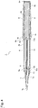
- FIG. 1 is a perspective view illustrating the configuration of the intraocular lens injection device according to an embodiment of the present invention
- FIG. 2 is an exploded perspective view illustrating the configuration of the intraocular lens injection device according to an embodiment of the present invention.
- An intraocular lens injection device 100 has a configuration roughly including an intraocular lens injector 1, a case 2 for housing the intraocular lens injector 1 therein, and a case cover 3.
- These configuration members are made of synthetic resin respectively, and can be obtained by an integral molding of resin.
- each configuration member is configured by suitably combining a plurality of components (integral molding of resin) excluding the case cover 3.
- X1 direction is set as a tip side (front side)
- X2 direction is set as a rear end side (back side)
- Y1 direction is set as a left side (leftward)
- Y2 direction is set as a right side (rightward)
- Z1 direction is set as an upper side (upward)
- Z2 direction is set as a lower side (downward).
- X1 direction and X2 direction correspond to an axial direction of the intraocular lens injection device 100
- Y1 direction and Y2 direction correspond to a width direction of the intraocular injection device 100
- Z1 direction and Z2 direction correspond to a height direction of the intraocular lens injection device 100.
- the intraocular lens injection device 100 is supplied in a state of being housed (sealed) in a sterile bag. Then, a state in which the intraocular lens injection device 100 is housed in the sterile bag, or a state in which the intraocular lens injection device 100 is simply taken out from the sterile bag and no operation is applied thereto, is an initial state before use.
- FIG. 1 illustrates the initial state before use.
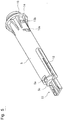
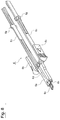
- FIG. 3 is a perspective view illustrating a configuration of the intraocular lens injector
- FIG. 4 is a cross-sectional view illustrating the configuration of the intraocular lens injector.
- the intraocular lens injector 1 is used in surgery to inject the intraocular lens into an eye.
- This embodiment handles an intraocular lens 4 as an example of the intraocular lens, which is made of a soft material such as silicone elastomer, etc., (see FIG. 6 ), having a circular optical portion 4a that functions optically, two support portions 4b that curve from two places on an outer circumferential part of the optical portion 4a so as to extend outwardly.
- the intraocular lens injector 1 is configured including an injector body 5, a slider 6, an injection tube 7, a screw member 8 as a rotating member, a plunger 9, and a rod 10.
- the slider 6 is mounted on the injector body 5.
- the injector body 5, the injection tube 7, and the screw member 8 are mutually connected to thereby configure a hollow body.
- the plunger 9 and the rod 10 are mutually connected to thereby configure a moving member.
- the injection tube 7 is connected to the tip portion of the injector body 5, and the screw member 8 is connected to the rear end portion of the injector body 5.
- the rod 10 is connected to the tip portion of the plunger 9.
- the moving member including the plunger 9 and the rod 10 is housed in an interior of the hollow body composed of the injector body 5, the injection tube 7, and the screw member 8. Further detailed explanation will be give hereafter.
- FIG. 5 is a perspective view illustrating the configuration of the injector body.
- the injector body 5 is formed into a cylindrical shape as a whole.
- a lens placement portion 11 is provided on the tip portion of the injector body 5.
- the intraocular lens 4 is placed on the lens placement portion 11.
- the lens placement portion 11 is formed so as to protrude frontward from a lower side outer circumferential wall of the injector body 5.
- an injection tube connecting portion 5a is formed on a tip side circumferential part of the injection body 5.
- a slit 12, a pre-stage locking hole 13a, and a subsequent stage locking hole 13b are formed respectively on both sides of the injector body 5.
- the slit 12 is formed on the tip side of the injector body 5.
- the slit 12 movably (slidably) supports the slider 6 in a central axial direction of the injector body 5, when the slider 6 is mounted on the injector body 5.
- a recess groove 5b (see FIG. 4 ) is formed on an inner circumferential surface of the injector body 5.
- the recess groove 5b is formed in parallel to the axial direction of the injector body 5.
- the recess groove 5b is formed into a thin and long shape (elongated) over a full length of the injector body 5, excluding the lens placement portion 11 and the injection tube connecting portion 5a. Further, a slider engagement portion 5c is formed on the inner circumferential surface of the upper side injection connecting portion 5a. The slider engagement portion 5c functions to guide a movement of the slider 6, and is formed so as to be recessed into U-shape.
- the pre-stage locking hole 13a and the subsequent stage locking hole 13b are formed on the rear end side of the injector body 5.
- the pre-stage locking hole 13a is an element of a reverse return prevention mechanism for preventing a reverse return of the slider 6 when the slider 6 is moved frontward in using the intraocular lens injector 1. Other element of the reverse return prevention mechanism will be described later.
- the reverse return of the slider 6 means a backward (in reverse direction) movement of the slider 6 after moving the slider 6 frontward.
- the subsequent stage locking hole 13b is formed on more rear end side of the injector body 5 than the pre-stage locking hole 13a.
- the subsequent stage locking hole 13b is the hole for positioning the slider 6 in the axial direction of the injector body 5.
- a flange 14 and a rotation support portion 15 are formed on the rear end portion of the injector body 5.
- the rotation support portion 15 is formed in a state of protruding backward of the flange 14.
- the rotation support portion 15 is formed into a cylindrical shape having a stepped configuration protruding into a ring shape.
- the rear end of the rotation support portion 15 is opened in a circular shape.
- the lens placement portion 11 includes a bottom surface portion 11a, lens receiving portions 11b, and lens guide portions 11c.
- the lens receiving portions 11b are configured to receive and support the intraocular lens 4 from below.
- the intraocular lens injector 1 is configured as a preload type in which the intraocular lens 4 is previously placed on the injector body 5. At this time, the intraocular lens 4 is placed in a state in which one of the support portions 4b is placed in front, and the other support portion 4b is placed in back.
- the lens receiving portions 11b are formed on both right and left sides of the lens placement portion 11.
- the lens receiving portion 11b is formed so as to be one step higher than the bottom surface portion 11a. This is because when the intraocular lens 4 is supported by placing it on the lens receiving portion 11b, the intraocular lens 4 is supported in a state floating from the bottom surface portion 11a in not contact with the bottom surface portion 11 a.
- the lens guide portions 11c are formed on both right and left sides of the lens placement portion 11.
- the lens guide portions 11c are configured to guide the optical portion 4a of the intraocular lens 4 supported by the lens receiving portions 11b, so as to sandwich the optical portion 4a from both right and left sides.
- the lens guide portions 11c are formed in a vertically rise state from the lens receiving portions 11b.
- Inclined surfaces 11d and restricting portions 11e are formed on upper end portions of the right and left lens guide portions 11c so as to be adjacent to each other in the axial direction of the injector body 5.
- the inclined surfaces 11d are formed in an open-out shape so as to easily receive the intraocular lens 4 into the lens placement portion 11.
- the inclined surfaces 11d are formed on more tip side of the lens placement portion 11 than the restricting portions 11e in the axial direction of the injector body 5.
- the restricting portions 11e are configured to restrict a vertical movable range of the intraocular lens 4 supported by the lens receiving portion 11b.
- FIG. 8 is a perspective view illustrating the configuration of the slider
- FIG. 9 is a plan view illustrating the configuration of the slider.
- the slider 6 is configured including a tip portion 6a, a pair of right and left wing portions 6b, and a pair of right and left leg portions 6c.
- the tip portion 6a is disposed on the tip portion of the slider 6.
- the tip portion 6a has a lens abutting portion 6h.
- the lens abutting portion 6h is a portion abutting on the intraocular lens 4 when the intraocular lens 4 is deformed into a prescribed shape by moving the slider 6.
- a guide rib 6d is formed on an upper surface of the tip portion 6a.
- the guide rib 6d is formed in the central part of the tip portion 6a in the width direction, in parallel to a longitudinal direction of the slider 6.
- the guide rib 6d is a portion engaging with the slider engagement portion 5c of the injector body 5.
- a lens pressing portion 6e is formed on the tip of the tip portion 6a.
- the lens pressing portion 6e extends frontward form the tip portion 6a.
- the lens pressing portion 6e is disposed in an upper part of the optical portion 4a of the intraocular lens 4 when the slider 6 is moved frontward (called a forward movement hereafter) from the initial state before use.
- a groove part (not illustrated) for guiding the movement of the rod 10, is formed on a lower surface of the tip portion 6a.
- a pair of wing portions 6b is disposed outside of an outer wall portion of the injector body 5.
- a pair of wing portions 6b is the portions on which fingers (usually an index finger and thumb) of a user are added when the slider 6 is moved in the axial direction of the injector body 5 during use of the intraocular lens injector 1.
- the user refers to an operator such as an ophthalmologist who performs surgery, or a nurse who assists the operator.
- Irregularities for preventing slip or a mark indicating a moving direction of the slider 6 is formed on an outside surface of each wing portion 6b.
- each wing portion 6b is curved toward the tip side from the rear end side so that the fingers of the user are easily caught, and the irregularities for preventing slip are formed on the curved portion.
- the wing portions 6b and the leg portions 6c are connected by shoulder portions 6f.
- Each shoulder portion 6f is a portion inserted (engaged) into/with the slit 12 of the injector body 5.
- the shoulder portion 6f is formed into a plate shape with a thickness corresponding to the width of the slit 12. Suitable gaps are formed between inner surfaces of the wing portions 6b and outer surfaces of the leg portions 6c.
- a pair of leg portions 6c is disposed inside of the injector body 5, along the outer wall inner surface of the injector body 5.
- a stopper 6g is formed on each leg portion 6c.
- the stopper 6g is formed into a protruding shape on the outer surface of the leg portion 6c.
- the stopper 6g is formed corresponding to the abovementioned pre-stage locking hole 13a and the subsequent stage locking hole 13b of the injector body 5.
- the stopper 6g is other element of the abovementioned reverse return prevention mechanism.
- FIG. 10 is a perspective view illustrating the configuration of the injection tube.
- An injection tube 7 is configured to fold the intraocular lens 4 to be small and guide it into the eye, when the intraocular lens 4 is injected into the eye, the intraocular lens 4 being placed on the lens placement portion 11.
- the injection tube 7 includes a hollow injection tube body 7a and a thin tubular nozzle 7b.
- the injection tube 7 is mounted on the tip portion of the injector body 5.
- the lens placement portion 11 of the injector body 5 is disposed so as to be housed in the injection tube body 7a of the injection tube 7.
- a receiving hole 7c is formed on an upper surface of the injection tube body 7a.
- a hole (not illustrated) into which a tacking pin described later can be inserted, is formed on a lower surface of the injection tube body 7a.
- the rear end portion of the injection tube body 7a is opened, and a hook portion 7d and a wedge portion 7e are formed around the opening part.
- the hook portion 7d is a portion for hooking on the injection tube connecting portion 5a of the injector body 5, when the injection tube 7 is mounted on the tip portion of the injector body 5.
- the wedge portion 7e is a portion inserted into an entrance of the slit 12 of the injector body 5, when the injection tube 7 is mounted on the injector body 5.
- the tip side diameter of the injection tube body 7a becomes gradually smaller.
- the nozzle 7b is formed on the tip portion of the injection tube 7.
- the tip portion of the nozzle 7b is opened with an oblique cut.
- the tip portion of the nozzle 7b is a portion inserted into an incision of an eyeball, when the intraocular lens 4 is injected into the eye using the injector body 5.
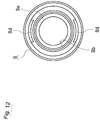
- FIG. 11 is a perspective view illustrating the configuration of the screw member
- FIG. 12 is a front view illustrating the configuration of the screw member.
- the screw member 8 is coaxially connected to the rear end portion of the injector body 5. In such a connection state, the screw member 8 is rotatably supported around the axis of the injector body 5.
- the screw member 8 is formed into a cylindrical shape.
- the tip portion and the rear end portion of the screw member 8 are opened in a circular shape respectively.
- a plurality of protrusions 8a are formed on the outer circumferential surface of the screw member 8.
- Each protrusion 8a is formed in parallel to the longitudinal direction of the screw member 8. Further, eight protrusions 8a in total are formed at an even angle pitch in a circumferential direction of eth screw member 8.
- the screw member 8 is a portion which is rotary-operated by the user.
- a first threaded portion 8b is formed on the inner circumferential surface of the screw member 8.
- the first threaded portion 8b constitutes a female screw.
- the first threaded portion 8b is formed substantially over an entire part of the axial direction of the screw member 8.
- Two window parts 8c are formed on the tip portion of the screw member 8. Two window parts 8c are formed at intervals of 180 degrees in the circumferential direction.
- the window parts 8c are configured to visually confirm whether the injector body 5 and the screw member 8 are properly connected.
- a pair of hook claws 8d is formed on the tip side inner circumferential part of the screw member 8.
- the hook claws 8d are formed on a tip side opening edge of the screw member 8 adjacent to the window part 8c.
- An abutting portion 8e is formed on the rear end portion of the screw member 8.
- the abutting portion 8e is formed by bending it inwardly so as to narrow an opening diameter of the rear end portion of the screw member 8.
- the abutting portion 8e is the portion on which the rear end portion of the plunger 9 is abutted, so that the plunger 9 is not protruded from the rear end portion of the screw member 8.
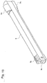
- FIG. 13 is a perspective view illustrating the configuration of the plunger.
- the plunger 9 is configured to move so that the injector body 5 and the screw member 8 move through the hollow part in the axial direction of the injector body 5.
- the plunger 9 is formed into a substantially prismatic shape.
- the plunger 9 is disposed in a state of being inserted into the screw member 8 so as not to be protruded from the rear end portion of the screw member 8, in the initial state before use.
- a connecting hole 9a is formed on a tip surface of the plunger 9.
- the connecting hole 9a is the hole for connecting the rod 10 to the tip portion of the plunger 9.
- a projection 9b is formed on the upper surface of the tip of the plunger 9, and corresponding thereto, a recessed groove 5b is formed on the inner circumferential surface of the injector body 5.
- the recessed groove 5b is configured to guide the plunger 9 movably in the axial direction of the injector body 5, by engaging with the projection 9b.
- a second threaded portion 9c is formed on the rear end portion of the plunger 9.
- the second threaded portion 9c constitutes a male screw, and is in a state always engaging with the first threaded portion 8b of the screw member 8.
- the second threaded portion 9c is formed as a pair formed in upper and lower parts of the plunger 9.
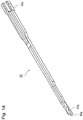
- FIG. 14 is a perspective view illustrating the configuration of the rod.
- the rod 10 is configured to release the intraocular lens 4 placed on the lens placement portion 11, from an opening part of the nozzle 7b of the injection tube 7.
- the rod 10 is formed into an elongated (thin and long) shape.
- a first contact part 10a and a second contact part 10b are formed on the tip portion of the rod 10.
- the first contact part 10a is brought into contact with the optical portion 4a
- the second contact part 10b is brought into contact with the support portion 4b.
- An insertion portion 10c is formed on the rear end portion of the rod 10.
- the inserting portion 10c is the portion inserted into the connecting hole 9a of the plunger 9 when the rod 10 is connected to the plunger 9.
- the case 2 is configured including a front case 21 and a back case 22.
- FIG. 15 is a perspective view illustrating the configuration of the front case
- FIG. 16 is a plan view illustrating the configuration of the front case.
- the front case 21 has a pair of right and left side plates 21 a, a front plate 21b, and a bottom plate 21c.
- Two receiving plates 21d and 21e are bridged over the right and left side plates 21 a.
- An upper central part of each receiving plate 21d, 21e is notched into substantially U-shape respectively, so that the injection tube 7 is fitted and supported into/by the notched portion.
- a shelf part 21f is formed on a back side of the receiving plate 21e, and a tacking pin 21 g is provided on the upper surface of the shelf part 21f.
- the tacking pin 21 g is provided in a state of protruding upward.
- the rear end portion of the front case 21 is formed into stepped structure of upper and lower two stages.
- a connecting pin 21h is provided on an upper stage, and a connecting pin 21 i is provided on a lower stage.
- the connecting pins 21h and 21 i are provided in right and left, one by one.
- Three holes 21j, 21k, and 21m, with positions shifted longitudinally, and a hook portion 21n are provided on the bottom plate 21c of the front case 21.
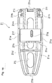
- FIG. 17 is a perspective view illustrating the configuration of a back case
- FIG. 18 is a plan view illustrating the configuration of the back case.
- the back case 22 has a pair of right and left side plates 22a, a back plate 22b, and a bottom plate 22c.
- a takeout recess portion 22d On the right and left side plates 22a, a takeout recess portion 22d, a step portion 22e, and an engaging recess portion 22f are formed.
- the takeout recess portion 22d is formed so as to be notched downward from an upper side of the side plate 22a.
- the takeout recess portion 22d is formed so that a wing portion 6b of the slider 6 can be vertically retracted.
- the step portion 22e is the portion for mounting the case cover 3 on the case 2.
- the step portion 22e is also formed on the tip side lower part of the takeout recess portion 22d.
- the step portion 22e is formed so as to be slightly recessed inward of the side plate 22a.
- a protrusion 22g is formed on a lower end portion of the step potion 22e.
- the engaging recess portion 22f is formed in communication with the takeout recess portion 22d.
- the engaging recess portion 22f is formed by extending a part of the side plate 22a frontward.
- An arrow 22h enclosing the number "3" for indicating an operation procedure when using the intraocular lens injector 1, is formed in the vicinity of the engaging recess portion 22f.
- the arrow 22h indicates an operation direction for moving the slider 6 in the axial direction of the injector body 5.
- the arrow 22h is formed on an outside surface of each side plate 22a, integrally with the side plate 22a by resin molding.
- a pair of right and left connecting portions 22i is formed on the tip portion of the back case 22.
- the right and left connecting portions 22i guides the intraocular lens injector 1 to a prescribed housing position by sandwiching a connecting portion of the injector body 5 and the injection tube 7 from both sides.
- Each connecting portion 22i has a stepped structure corresponding to arrangements of connecting pins 21h and 21i of the front case 21.
- a communicating hole (not illustrated) that can be engaged with the connecting pin 21i is formed on an upper stage side of the connecting portion 21i, and a communicating hole (not illustrated) that can be engaged with the connecting pin 21i is formed on a lower stage side of the connecting portion 21i.
- a claw 22j is formed on the tip portion of the back case 22. When the front case 21 and the back case 22 are connected, the claw 22j is the portion on which a hook portion 21n of the front case 21 is hooked.
- the receiving plates 22k, 22m, 22n, 22p, 22q, and 22r in total are bridged over the right and left side plates 22a.
- the receiving plates 22k, 22m, and 22n are the plates for receiving and supporting the injector body 5 from under
- the receiving plates 22p and 22q are the plates for supporting the screw member 8 from under, when the intraocular lens injector 1 is housed in the case 2.
- the receiving plate 22r is the plate for receiving and supporting the rear end portion of the screw member 8 from under.
- a handle 22s is formed on a back plate 22b.
- the handle 22s is the portion gripped by a user, when the user takes out the intraocular lens injection device 100 from a sterile bag.
- Two holes 22t and 22u are formed on the bottom plate 22c, with positions shifted in a back-and-forth direction.
- the hole 22t is formed between the receiving plate 22k and the receiving plate 22m in a longitudinal direction of the back case 22, and the hole 22u is formed between the receiving plate 22q and the receiving plate 22r.
- the hole 22t is a long hole in which a width direction of the back case 22 is a long axial direction.
- Guide pieces 22v are formed on an inner surface of the right and left side plates 22a respectively corresponding to the positions of the holes 22t.
- the right and left guide pieces 22v are the pieces for guiding the intraocular lens injector 1 to a prescribed position by sandwiching the injector body 5 from both sides.
- the right and left side plates 22a are notched into an arc shape in a side view.
- the front case 21 and the back case 22 having the abovementioned configurations are connected as follows. Namely, two connecting pins 21h and 21i formed on stepped structures on the rear end portion of the front case 21, are fitted into two holes (not illustrated) formed on the stepped structure of the connecting portion 22i of the back case 22. Also, the hook portion 21n formed on the rear end portion of the front case 21 is locked on the claw 22j formed on the tip portion of the back case 22 corresponding to the hook portion 21n.
- the case 2 is constituted.
- FIG. 19 is a perspective view illustrating the configuration of the case cover.
- the case cover 3 has a plate-shaped cover body 3a, a pair of right and left holding pieces 3b, and a pair of right and left movable pieces 3c.
- An injection port 3d is formed on the tip portion of the cover body 3 a.
- the injection port 3d is the port for injecting a viscoelastic substance (such as hyaluronate sodium).
- An upper part of the injection port 3d is opened into a bowl shape.
- a pipe 3e is formed just under the injection port 3d.
- the pipe 3e is protruded downward coaxially with the injection port 3d.
- the pipe 3e has a hole continued to the pipe 3e.
- the pipe 3e is the pipe for releasing the viscoelastic substance which is injected from the injection port 3d, to the vicinity of the intraocular lens 4 placed on the lens placement portion 11 of the injector body 5, by being inserted into the receiving hole 7c of the injection tube 7.
- Mark “3f” of numeral "1" is engraved in the vicinity of the injection port 3d, for indicating the operation procedure when using the intraocular lens injector 1.
- the engraved mark “3f” is integrally formed on the upper surface of the cover body 3a by resin molding.
- a pair of right and left arrows 3g are formed, enclosing numeral "2" that indicates the operation procedure when using the intraocular lens injector 1.
- the arrows 3g indicate the operation direction when operating right and left movable pieces 3c so as to sandwich them by fingers.
- a pair of clamping pieces 3b is formed to hang down from right and left both sides of the cover body 3a.
- Each side view shape of the clamping pieces 3b is formed corresponding to the side view shapes of the takeout recess portion 22d and the step portion 22e of the front case 21.
- a pair of movable pieces 3c is provided on right and left both sides of the cover body 3a.
- the movable pieces 3c are connected to the clamping pieces 3b in the vicinity of the lower edges of the clamping pieces 3b.
- the movable pieces 3c are disposed slightly inclined with respect to the clamping pieces 3b, so that a V-shaped gap is formed between the clamping pieces 3b and the movable pieces 3c.
- Each movable piece 3c is formed to be thicker than each clamping piece 3b.
- Drain holes 3h and locking members 3i are formed on the movable pieces 3c.
- Each drain hole 3h is formed in a long rectangular shape in a vertical direction.
- the locking member 3i is formed on the lower end portion of each movable piece 3c. When the case cover 3 is mounted on the case 2, the locking member 3i is the portion where the protrusion 22g of the back case 22 is locked.
- the slider 6 is attached to the injector body 5.
- the leg portion 6c of the slider 6 is inserted from a tip side opening part of the injector body 5.
- the shoulder portion 6f of the slider 6 is inserted and engaged into/with the slit 12 of the injector body 5, and the slider 6 is pushed-in backward in this state.
- the stopper 6g of the slider 6 is caught in the pre-stage locking hole 13a of the injector body 5, and the slider 6 cannot be pushed-in any more. Therefore, when the slider 6 is attached to the injector body 5, an assembly jig 31 illustrated in FIG. 20 is used.
- the assembly jig 31 has a pair of release levers 32.
- the pair of release levers is the lever for preventing the stopper 6g from being caught in the pre-stage locking hole 13a.
- the plunger 9 is attached to the screw member 8. Specifically, the screw member 8 is fitted into the rear end portion of the plunger 9 so as to cover the tip side opening of the screw member 8, to thereby rotate the screw member 8. Thus, the first threaded portion 8b and the second threaded portion 9c are engaged with each other. Therefore, when the plunger 9 is fixed and the screw member 8 is rotated, the plunger 9 is inserted into the screw member 8, with a rotation of the screw member 8. At this time, the screw member 8 is rotated until the rear end portion of the plunger 9 abuts on the abutting portion 8e of the screw member 8.
- the rear end portion of the plunger 9 is disposed at a position slightly retracted inward of the rear end portion of the screw member 8. Further, the tip portion of the plunger 9 is disposed in a state of protruding slightly frontward of the tip portion of the screw member 8.
- the rod 10 is attached to the plunger 9. Specifically, the inserting portion 10c of the rod 10 is inserted into the connecting hole 9a of the plunger 9. Thus, the connecting hole 9a and the inserting portion 10c are caught in each other, and the rod 10 cannot be slipped-off from the plunger 9.
- the tip portion of the screw member 8 is connected to the rear end portion of the injector body 5.
- the rod 10 is inserted into the injector body 5 from backward.
- the tip side of the rod 10 is passed through the bottom of the tip portion 6a of the slider 6.
- the projection 9b of the plunger 9 is engaged with the recess groove 5b of the injector body 5, and in this state, the screw member 8 is connected to the injector body 5.
- the screw member 8 is slightly strongly pushed-in to the injector body 5, so that the hook claw 8d of the screw member 8 can overcome a ledge portion of the rotation support portion 15.
- the screw member 8 is freely rotatably connected to the rear end portion of the injector body 5.
- the injector body 5 and the screw member 8 connected to each other as described above, are housed in the back case 22.
- the slider 6 is moved frontward before the injector body 5 and the screw member 8 are housed in the back case 22.
- the wing portion 6b of the slider 6 is caught by the side plate 22a of the back case 22 in a state when the slider 6 is moved backward.
- the stopper 6g is caught in the pre-stage locking hole 13a of the injector body 5, thus preventing the slider 6 from returning backward. Therefore, the abovementioned assembly jig 31 is set in the back case 22.
- the release lever 32 of the assembly jig 31 is disposed in the back case 22 through the hole 22t of the back case 22.
- the slider 6 is pushed backward until the stopper 6g is caught in the subsequent stage locking hole 13b.
- the stopper 6g of the slider 6 passes through the pre-stage locking hole 13a of the injector body 5 and is fitted into the subsequent stage locking hole 13b.
- the slider 6 is positioned at a prescribed position in the axial direction of the injector body 5.
- the assembly jig 31 is removed from back case 22.
- the intraocular lens 4 is placed on the lens placement portion 11 of the injector body 5.
- the optical portion 4a of the intraocular lens 4 is placed on the lens receiving portion 11b.
- one of the support portions 4b of the intraocular lens 4 is disposed in front, and the other support portion 4b is disposed in the back.
- the injection tube 7 is attached to the tip portion of the injector body 5.
- the hook portion 7d of the injection tube 7 is hooked on the injection tube connecting portion 5a of the injector body 5 to be engaged.
- the wedge portion 7e of the injection tube 7 is inserted into the slit 12 of the injector body 5.
- the case cover 3 is attached to the back case 22.
- the case cover 3 is disposed to cover the back case 22 from above, while the clamping piece 3b of the case cover 3 is positioned at the step portion 22e of the back case 22.
- the protrusion 22g of the back case 22 is caught by the locking member 3i of the movable piece 3c to be locked.
- the pipe 3e of the case cover 3 is inserted into the receiving hole 7c of the injection tube 7.
- the front case 21 is attached to the back case 22.
- the tacking pin 21 g of the front case 21 is inserted into the hole (not illustrated) provided on a lower surface of the injection tube 7.
- the tacking pin 21g is disposed slightly frontward of the intraocular lens 4 which is placed on the lens placement portion 11.
- the assembly of the intraocular lens injector 1 incorporating the intraocular lens 4, and the assembly of the intraocular lens injection device 100 in a state that the intraocular lens injector 1 is housed in the case 2 and the case cover 3 is mounted thereon, are completed.
- the intraocular lens injection device 100 whose assembly is completed, is housed in a sterile bag not illustrated.
- a method of using the intraocular lens injection device 100 will be described next.
- the intraocular lens injection device 100 is supplied to a user in a state of being housed in the sterile bag not illustrated. Therefore, the user opens the sterile bag and takes out the intraocular lens injection device 100 from the sterile bag while holding a handle 22s.
- the user operates the intraocular lens injection device 100 in accordance with the operation procedure indicated by the engraved mark 3f or arrow 3g of the case cover 3, and arrow 22h of the case 2.
- the engraved mark 3f indicates "1" as the operation procedure
- arrow 3g indicates “2” as the operation procedure
- arrow 22h indicates "3" as the operation procedure. Therefore, the user performs the following work in an order of the operation procedure 1" ⁇ "2" ⁇ "3".
- the user injects the viscoelastic substance into the injection port 3d of the case cover 3 in accordance with the operation procedure indicated by the engraved mark 3f of the case cover 3.
- the injected viscoelastic substance is supplied to the intraocular lens 4 from the injection port 3d through the pipe 3e.
- the user removes the case cover 3 from the case 2.
- the user sandwiches the upper part of the pair of movable pieces 3c from right and left both sides in accordance with the operation procedure and the operation direction indicated by the arrow 3g of the case cover 3.
- the lower part of each movable piece 3c is displaced to outside, and accordingly the lower part of the clamping piece 3b is also displaced to outside.
- a lock state of the protrusion 22g of the injector body 5 and the locking member 3i of the case cover 3 is canceled. Therefore, by pulling-up the case cover 3, with a pair of movable pieces 3c sandwiched from both sides, the user removes the case cover 3 from the case 2.
- the wing portion 6b of the slider 6 is engaged with the engaging recess portion 22f, thus preventing the takeout of the intraocular lens injector 1 from the case 2.
- the user moves the slider 6 frontward.
- the user moves the slider 6 frontward in accordance with the operation procedure and the operation direction indicated by the arrow 22h of the injector body 5.
- the wing portion 6b of the slider 6 moves to the takeout recess portion 22d from the engaging recess portion 22f. Therefore, a state of preventing the takeout of the intraocular lens injector 1 (called a takeout prevention state), is canceled.
- the stopper 6g of the leg portion 6c is separated from the subsequent stage locking hole 13b of the injector body 5 due to advancement of the slider 6, and fitted into the pre-stage locking hole 13a. Accordingly, reverse return of the slider 6 is prevented.
- the lens abutting portion 6h of the slider 6 abuts on the intraocular lens 4 due to the movement of the slider 6, thus pushing out the intraocular lens 4 in this stated.
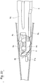
- the intraocular lens 4 is deformed into a prescribed shape. Specifically, as illustrated in FIG. 22 , the support portion 4b disposed in front is pushed against the tacking pin 21g of the front case 21 and folded back toward the optical portion 4a, and the support portion 4b disposed in back is pushed against the lens abutting portion 6g and folded back toward the optical portion 4a.
- the user takes out the intraocular lens injector 1 from the case 2.
- the wing portion 6b advances to a point of the takeout recess portion 22d due to the abovementioned movement of the slider 6, thus canceling the takeout prevention state, and therefore the intraocular lens injector 1 is taken out from the case 2.
- the user releases the intraocular lens 4 from the tip of the injection tube 7.
- the intraocular lens 4 is inserted into the eye. Further, the shape of the intraocular lens 4 after inserting into the eye, is restored to its original shape.
- the operation of the intraocular lens injector 1 is performed by rotating the screw member 8 in one direction (referred to as a "positive rotation” hereafter).
- the first threaded portion 8b of the screw member 8 and the second threaded portion 9c of the plunger 9 are always engaged with each other, including an initial state before use. Therefore, at the time of the positive rotation of the screw member 8, simultaneously with this rotation, the plunger 9 starts to move toward the injector body 5 (frontward). Further, at the time of the rotation of the screw member 8 in a reverse direction by the user accidentally in the initial state before use, the rear end portion of the plunger 9 abuts on the abutting portion 8e of the screw member 8. Therefore, the reverse rotation (misoperation) of the screw member 8 is prevented.
- the abutting portion 8e of the screw member 8 and the rear end portion of the plunger 9 that abuts on the abutting portion 8e constitute a reverse rotation prevention mechanism of preventing the reverse rotation of the screw member 8 in the initial state before use.
- the positive rotation of the screw member 8 refers to the rotation of the screw member 8 when the plunger 9 moves frontward by the engagement of the threaded portions when the screw member 8 is rotated.
- the reverse rotation of the screw member 8 refers to the rotation of the screw member 8 when the plunger 9 is moved backward by the engagement of the threaded portions when the screw member 8 is rotated.
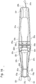
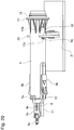
- FIG. 23 is a cross-sectional view illustrating a positional relation of each portion before the slider is moved forward (initial state before use), and FIG. 24 is a cross-sectional view illustrating the positional relation of each portion after the slider is moved frontward.
- FIG. 25 is a cross-sectional view illustrating the positional relation of each portion when the screw member is rotated by one rotation from the initial state
- FIG. 26 is a cross-sectional view illustrating the positional relation of each portion when the screw member is rotated by two rotations from the initial state
- FIG. 27 is a cross-sectional view illustrating the positional relation of each portion when the screw member is rotated by three rotations from the initial state.
- signs and numerals of each member and description of the intraocular lens are omitted.
- the rear end portion of the plunger 9 is disposed slightly inward (frontward) of the rear end portion of the screw member 8. Further, each member of the slider 6, the plunger 9, and the rod 10 is not protruded to outside of the hollow body which is composed of the injector body 5, the injection tube 7, and the screw member 8, excluding the wing portion 6b and the shoulder portion 6f of the slider 6. The same is applied in the stage illustrated in FIG. 24 to FIG. 26 .
- the intraocular lens 4 is deformed due to the advancement of the slider 6, as illustrated in FIG. 22 .
- the tip of the rod 10 is in a state of being brought into contact with the intraocular lens 4 due to the movement of the plunger 9.
- the intraocular lens 4 is pushed out to the vicinity of the tip of the injection tube 7, which is the tip of the rod 10, due to the movement of the plunger 9.
- the intraocular lens 4 is in a small folded state, in the form in which two support portions 4b are folded back toward the optical portion 4a.
- the tip of the rod 10 is protruded frontward from tip of the injection tube 7, due to the movement of the plunger 9.
- the intraocular lens 4 is released in the small folded state as described above.
- the intraocular lens injector 1 is actually used, the intraocular lens 4 is released slightly before the stage illustrated in FIG. 27 , specifically in the stage when the tip of the rod 10 is slightly protruded from the tip of the injection tube 7. Therefore, there is almost no change in the full length of the intraocular lens injector 1, from start to end of the operation of the intraocular lens injector 1.
- the intraocular lens injection device 100 of the embodiments of the present invention the following effect is obtained.
- a moving member is constituted by preparing the plunger 9 and the rod 10 as separate components, and connecting them.
- the plunger 9 and the rod 10 can be integrally formed by resin molding.
Landscapes
- Health & Medical Sciences (AREA)
- Ophthalmology & Optometry (AREA)
- Cardiology (AREA)
- Oral & Maxillofacial Surgery (AREA)
- Transplantation (AREA)
- Engineering & Computer Science (AREA)
- Biomedical Technology (AREA)
- Heart & Thoracic Surgery (AREA)
- Vascular Medicine (AREA)
- Life Sciences & Earth Sciences (AREA)
- Animal Behavior & Ethology (AREA)
- General Health & Medical Sciences (AREA)
- Public Health (AREA)
- Veterinary Medicine (AREA)
- Prostheses (AREA)
Abstract
Description
- The present invention relates to an intraocular lens injector used for injecting an intraocular lens into an eye, and an intraocular lens injection device having the same.
- In a cataract surgery, removal of a cloudy lens by phacoemulsification, and an implantation into an eye after removal of the lens, are generally performed. Then, at present, a soft intraocular lens made of a soft material such as silicone elastomer or soft acryl, etc., is injected into an eye using an intraocular lens injector. As this type of the intraocular lens injector, for example, the intraocular lens injector disclosed in
patent documents - In the intraocular lens injector disclosed in
patent document 1, a threaded portion (female screw) is formed on an inner peripheral surface of a screw member, and a threaded portion (male screw) is formed on an outer peripheral surface of the injector body corresponding to the female screw. An injection tube is provided on a tip portion of the injector body. Further, a plunger is inserted into the screw member, and a rod is connected to the plunger. Then, in an initial state before using the intraocular lens injector, the threaded portion of the screw member and the threaded portion of the injector body are set in separated states without engaging the threaded portion of the screw member and the threaded portion of the injector body with each other. When the intraocular lens injector is actually used, in order to engage the threaded portion of the screw member and the threaded portion of the injector body, the screw member is pushed-in toward the injector body. Next, by rotating the screw member, the plunger is moved in an axial direction of the injector body by an engagement of the threaded portions, together with the screw member. At this time, a tip of the rod that moves together with the plunger, is brought into contact with the intraocular lens, and the intraocular lens is pushed-in in this state, to thereby release the intraocular lens from the tip of the injection tube. -
- Patent document 1: Japanese Patent Laid Open Publication No.
2011-255029 - Patent document 2: Japanese Unexamined Patent Application Publication No.
2007-533379 - However, in the intraocular lens injector disclosed in
patent document 1, the threaded portions are sometimes not engaged with each other smoothly when the screw member is pushed toward the injector body side. Therefore, when starting a rotation of the screw member, the threaded portions are disengaged instantaneously, a vibration or an impact occurs, thus possibly causing a shift of a position of the intraocular lens from a normal position. Further, when the screw member is pushed, the vibration, etc., occurs due to a collision between members, thus causing a similar problem. - The intraocular lens injector is configured to push the intraocular lens placed on a lens placement portion of the injector body, by the abovementioned tip of the rod. Therefore, if the positon of the intraocular lens is shifted from the normal position, the intraocular lens is properly folded when the intraocular lens is pushed by the tip of the rod, and clogging, etc., is likely to occur. Especially, a positional deviation of the intraocular lens is likely to cause the clogging, etc., in the intraocular lens injector of a type of placing the intraocular lens made of a soft material on the lens placement portion of the injector body, and making the intraocular lens in a small folded state, thereby deforming the intraocular lens in a prescribed shape, and thereafter pushing out the intraocular lens by the tip of the rod by moving the plunger.
- Further, the intraocular lens injector disclosed in
patent document 2 is configured to engage the treaded portion formed on a first operation member, and the threaded portion formed on a second operation member, by pushing the first operation member. Therefore, the similar problem as described above possibly occurs. - A main object of the present invention is to provide an intraocular lens injector in which a vibration, etc., hardly occurs during operation compared to a conventional one during use of the intraocular lens injector, and an intraocular lens injection device including the intraocular lens inj ector.
- According to a first aspect of the present invention, there is provided an intraocular lens injector, including:
- a hollow body having an injector body provided with a lens placement portion on which an intraocular lens is placed, and a rotating member with a first threaded portion formed thereon and connected to a rear end portion of the injector body, and rotatable around an axis of the injector body without moving in an axial direction of the injector body; and
- a moving member having a second threaded portion that engages with the first threaded portion from an initial state before use, and configured to release the intraocular lens from a tip of the hollow body by moving in an axial direction of the injector body independently from the rotating member due to an engagement of the first threaded portion and the second threaded portion, when the rotating member is rotary-operated.
- According to a second aspect of the present invention, there is provided the intraocular lens injector of the first aspect, wherein the moving member is housed in an interior of the hollow body without protruding from a rear end of the rotating member in the initial state before use, and configured to move in the interior of the hollow body when the rotating member is rotary-operated.
- According to a third aspect of the present invention, there is provided the intraocular lens injector of the first or the second aspect, having a reverse rotation prevention mechanism for preventing a reverse rotation of the rotating member in the initial state before use.
- According to a fourth aspect of the present invention, there is provided the intraocular lens injector of any one of the first to third aspects, wherein an intraocular lens is placed on the lens placement portion.
- According to a fifth aspect of the present invention, there is provided the intraocular lens injector of any one of the first to fourth aspects, including:
- a slider provided movably in an axial direction of the injector body, and configured to deform the intraocular lens into a prescribed shape, by abutting on the intraocular lens when moving it in one of the axial directions of the injector body; and
- a reverse return prevention mechanism configured to prevent a reverse return of the slider, when the slider is moved in one of the axial directions of the injector body.
- According to a sixth aspect of the present invention, there is provided an intraocular lens injection device, including:
- the intraocular lens injector of
claim 5; - a case configured to house the intraocular lens injector; and
- a takeout prevention mechanism configured to prevent takeout of the intraocular lens injector from the case, in a state of housing the intraocular lens injector in the case,
- According to the present invention, the vibration, etc., hardly occurs during operation compared to a conventional one, when using the intraocular lens injector. Therefore, occurrence of a defective shape and clogging, etc., of the intraocular lens caused by the vibration, etc., during operation, is suppressed.
-
-
FIG. 1 is a perspective view illustrating a configuration of an intraocular lens injection device according to an embodiment of the present invention. -
FIG. 2 is an exploded perspective view illustrating the configuration of the intraocular lens injection device according to an embodiment of the present invention. -
FIG. 3 is a perspective view illustrating the configuration of the intraocular lens injector. -
FIG. 4 is a cross-sectional view illustrating the configuration of the intraocular lens injector. -
FIG. 5 is a perspective view illustrating the configuration of an injector body. -
FIG. 6 is a perspective view expanding a tip portion of the injector body. -
FIG. 7 is a cross-sectional view in the vicinity of a lens placement portion of the intraocular lens injector. -
FIG. 8 is a perspective view illustrating a configuration of a slider. -
FIG. 9 is a plan view illustrating the configuration of the slider. -
FIG. 10 is a perspective view illustrating the configuration of an injection tube. -
FIG. 11 is a perspective view illustrating the configuration of a screw member. -
FIG. 12 is a front view illustrating the configuration of the screw member. -
FIG. 13 is a perspective view illustrating the configuration of a plunger. -
FIG. 14 is a perspective view illustrating the configuration of a rod. -
FIG. 15 is a perspective view illustrating the configuration of a front case. -
FIG. 16 is a plan view illustrating the configuration of the front case. -
FIG. 17 is a perspective view illustrating the configuration of a back case. -
FIG. 18 is a plan view illustrating the configuration of the back case. -
FIG. 19 is a perspective view illustrating the configuration of a case cover. -
FIG. 20 is a perspective view illustrating a state in which an injector body is set in an assembly jig. -
FIG. 21 is a perspective view illustrating an assembly composed of the screw member, the plunger, and the rod. -
FIG. 22 is a view illustrating a state of the intraocular lens when the slider is moved forward. -
FIG. 23 is a cross-sectional view illustrating a positional relation of each portion before the slider is moved forward. -
FIG. 24 is a cross-sectional view illustrating the positional relation of each portion after the slider is moved frontward. -
FIG. 25 is a cross-sectional view illustrating the positional relation of each portion when the screw member is rotated by one rotation from an initial state. -
FIG. 26 is a cross-sectional view illustrating the positional relation of each portion when the screw member is rotated by two rotations from the initial state. -
FIG. 27 is a cross-sectional view illustrating the positional relation of each portion when the screw member is rotated by three rotations from the initial state. - Embodiments of the present invention will be described hereafter, with reference to the drawings. The embodiments of the present invention will be described in the following order.
- 1. Configuration of an intraocular lens injection device
- 2. Configuration of an intraocular lens injector
- 3. Assembly method of the intraocular lens injection device
- 4. Use method of the intraocular lens injection device
- 5. Effect of the embodiment
- 6. Modified example, etc.
-
FIG. 1 is a perspective view illustrating the configuration of the intraocular lens injection device according to an embodiment of the present invention, andFIG. 2 is an exploded perspective view illustrating the configuration of the intraocular lens injection device according to an embodiment of the present invention. - An intraocular
lens injection device 100 has a configuration roughly including anintraocular lens injector 1, acase 2 for housing theintraocular lens injector 1 therein, and acase cover 3. These configuration members are made of synthetic resin respectively, and can be obtained by an integral molding of resin. However, each configuration member is configured by suitably combining a plurality of components (integral molding of resin) excluding thecase cover 3. By thus configuring an entire body of the intraocularlens injection device 100 by synthetic resin, mass production is facilitated. Therefore, the intraocularlens injection device 100 is provided as a disposable (throwaway) product. - In this embodiment, when a relative positional relation or an operation direction of each portion is described, as illustrated in
FIG. 1 , X1 direction is set as a tip side (front side), X2 direction is set as a rear end side (back side), Y1 direction is set as a left side (leftward), Y2 direction is set as a right side (rightward), Z1 direction is set as an upper side (upward), and Z2 direction is set as a lower side (downward). Among them, X1 direction and X2 direction correspond to an axial direction of the intraocularlens injection device 100, and Y1 direction and Y2 direction correspond to a width direction of theintraocular injection device 100, and Z1 direction and Z2 direction correspond to a height direction of the intraocularlens injection device 100. - Further, in this embodiment, the intraocular
lens injection device 100 is supplied in a state of being housed (sealed) in a sterile bag. Then, a state in which the intraocularlens injection device 100 is housed in the sterile bag, or a state in which the intraocularlens injection device 100 is simply taken out from the sterile bag and no operation is applied thereto, is an initial state before use.FIG. 1 illustrates the initial state before use. -
FIG. 3 is a perspective view illustrating a configuration of the intraocular lens injector, andFIG. 4 is a cross-sectional view illustrating the configuration of the intraocular lens injector. - The
intraocular lens injector 1 is used in surgery to inject the intraocular lens into an eye. This embodiment handles anintraocular lens 4 as an example of the intraocular lens, which is made of a soft material such as silicone elastomer, etc., (seeFIG. 6 ), having a circularoptical portion 4a that functions optically, twosupport portions 4b that curve from two places on an outer circumferential part of theoptical portion 4a so as to extend outwardly. - As illustrated in
FIG. 2 , theintraocular lens injector 1 is configured including aninjector body 5, aslider 6, aninjection tube 7, ascrew member 8 as a rotating member, aplunger 9, and arod 10. Theslider 6 is mounted on theinjector body 5. Theinjector body 5, theinjection tube 7, and thescrew member 8 are mutually connected to thereby configure a hollow body. Further, theplunger 9 and therod 10 are mutually connected to thereby configure a moving member. In configuring the hollow body, theinjection tube 7 is connected to the tip portion of theinjector body 5, and thescrew member 8 is connected to the rear end portion of theinjector body 5. Further, in configuring the moving member, therod 10 is connected to the tip portion of theplunger 9. The moving member including theplunger 9 and therod 10, is housed in an interior of the hollow body composed of theinjector body 5, theinjection tube 7, and thescrew member 8. Further detailed explanation will be give hereafter. -
FIG. 5 is a perspective view illustrating the configuration of the injector body. - The
injector body 5 is formed into a cylindrical shape as a whole. Alens placement portion 11 is provided on the tip portion of theinjector body 5. Theintraocular lens 4 is placed on thelens placement portion 11. Thelens placement portion 11 is formed so as to protrude frontward from a lower side outer circumferential wall of theinjector body 5. Further, an injectiontube connecting portion 5a is formed on a tip side circumferential part of theinjection body 5. - A
slit 12, apre-stage locking hole 13a, and a subsequentstage locking hole 13b are formed respectively on both sides of theinjector body 5. Theslit 12 is formed on the tip side of theinjector body 5. Theslit 12 movably (slidably) supports theslider 6 in a central axial direction of theinjector body 5, when theslider 6 is mounted on theinjector body 5. Arecess groove 5b (seeFIG. 4 ) is formed on an inner circumferential surface of theinjector body 5. Therecess groove 5b is formed in parallel to the axial direction of theinjector body 5. Therecess groove 5b is formed into a thin and long shape (elongated) over a full length of theinjector body 5, excluding thelens placement portion 11 and the injectiontube connecting portion 5a. Further, aslider engagement portion 5c is formed on the inner circumferential surface of the upper sideinjection connecting portion 5a. Theslider engagement portion 5c functions to guide a movement of theslider 6, and is formed so as to be recessed into U-shape. - The
pre-stage locking hole 13a and the subsequentstage locking hole 13b are formed on the rear end side of theinjector body 5. Thepre-stage locking hole 13a is an element of a reverse return prevention mechanism for preventing a reverse return of theslider 6 when theslider 6 is moved frontward in using theintraocular lens injector 1. Other element of the reverse return prevention mechanism will be described later. The reverse return of theslider 6 means a backward (in reverse direction) movement of theslider 6 after moving theslider 6 frontward. The subsequentstage locking hole 13b is formed on more rear end side of theinjector body 5 than thepre-stage locking hole 13a. The subsequentstage locking hole 13b is the hole for positioning theslider 6 in the axial direction of theinjector body 5. Aflange 14 and arotation support portion 15 are formed on the rear end portion of theinjector body 5. Therotation support portion 15 is formed in a state of protruding backward of theflange 14. Therotation support portion 15 is formed into a cylindrical shape having a stepped configuration protruding into a ring shape. The rear end of therotation support portion 15 is opened in a circular shape. - As illustrated in
FIG. 6 andFIG. 7 , thelens placement portion 11 includes abottom surface portion 11a,lens receiving portions 11b, andlens guide portions 11c. Thelens receiving portions 11b are configured to receive and support theintraocular lens 4 from below. Theintraocular lens injector 1 is configured as a preload type in which theintraocular lens 4 is previously placed on theinjector body 5. At this time, theintraocular lens 4 is placed in a state in which one of thesupport portions 4b is placed in front, and theother support portion 4b is placed in back. - A central part of the
bottom surface portion 11 a in a width direction, has a slightly recessed shape. Thelens receiving portions 11b are formed on both right and left sides of thelens placement portion 11. Thelens receiving portion 11b is formed so as to be one step higher than thebottom surface portion 11a. This is because when theintraocular lens 4 is supported by placing it on thelens receiving portion 11b, theintraocular lens 4 is supported in a state floating from thebottom surface portion 11a in not contact with thebottom surface portion 11 a. Similarly to thelens receiving portions 11b, thelens guide portions 11c are formed on both right and left sides of thelens placement portion 11. Thelens guide portions 11c are configured to guide theoptical portion 4a of theintraocular lens 4 supported by thelens receiving portions 11b, so as to sandwich theoptical portion 4a from both right and left sides. Thelens guide portions 11c are formed in a vertically rise state from thelens receiving portions 11b.Inclined surfaces 11d and restrictingportions 11e are formed on upper end portions of the right and leftlens guide portions 11c so as to be adjacent to each other in the axial direction of theinjector body 5. Theinclined surfaces 11d are formed in an open-out shape so as to easily receive theintraocular lens 4 into thelens placement portion 11. Theinclined surfaces 11d are formed on more tip side of thelens placement portion 11 than the restrictingportions 11e in the axial direction of theinjector body 5. The restrictingportions 11e are configured to restrict a vertical movable range of theintraocular lens 4 supported by thelens receiving portion 11b. -
FIG. 8 is a perspective view illustrating the configuration of the slider, andFIG. 9 is a plan view illustrating the configuration of the slider. - The
slider 6 is configured including atip portion 6a, a pair of right andleft wing portions 6b, and a pair of right andleft leg portions 6c. Thetip portion 6a is disposed on the tip portion of theslider 6. Thetip portion 6a has a lens abutting portion 6h. The lens abutting portion 6h is a portion abutting on theintraocular lens 4 when theintraocular lens 4 is deformed into a prescribed shape by moving theslider 6. Aguide rib 6d is formed on an upper surface of thetip portion 6a. Theguide rib 6d is formed in the central part of thetip portion 6a in the width direction, in parallel to a longitudinal direction of theslider 6. Theguide rib 6d is a portion engaging with theslider engagement portion 5c of theinjector body 5. Alens pressing portion 6e is formed on the tip of thetip portion 6a. Thelens pressing portion 6e extends frontward form thetip portion 6a. Thelens pressing portion 6e is disposed in an upper part of theoptical portion 4a of theintraocular lens 4 when theslider 6 is moved frontward (called a forward movement hereafter) from the initial state before use. A groove part (not illustrated) for guiding the movement of therod 10, is formed on a lower surface of thetip portion 6a. - A pair of
wing portions 6b is disposed outside of an outer wall portion of theinjector body 5. A pair ofwing portions 6b is the portions on which fingers (usually an index finger and thumb) of a user are added when theslider 6 is moved in the axial direction of theinjector body 5 during use of theintraocular lens injector 1. The user refers to an operator such as an ophthalmologist who performs surgery, or a nurse who assists the operator. Irregularities for preventing slip or a mark indicating a moving direction of the slider 6 (triangular arrow in this embodiment) is formed on an outside surface of eachwing portion 6b. Further, the outside surface of eachwing portion 6b is curved toward the tip side from the rear end side so that the fingers of the user are easily caught, and the irregularities for preventing slip are formed on the curved portion. Thewing portions 6b and theleg portions 6c are connected byshoulder portions 6f. Eachshoulder portion 6f is a portion inserted (engaged) into/with theslit 12 of theinjector body 5. Theshoulder portion 6f is formed into a plate shape with a thickness corresponding to the width of theslit 12. Suitable gaps are formed between inner surfaces of thewing portions 6b and outer surfaces of theleg portions 6c. - A pair of
leg portions 6c is disposed inside of theinjector body 5, along the outer wall inner surface of theinjector body 5. Astopper 6g is formed on eachleg portion 6c. Thestopper 6g is formed into a protruding shape on the outer surface of theleg portion 6c. Thestopper 6g is formed corresponding to the abovementionedpre-stage locking hole 13a and the subsequentstage locking hole 13b of theinjector body 5. Thestopper 6g is other element of the abovementioned reverse return prevention mechanism. -
FIG. 10 is a perspective view illustrating the configuration of the injection tube. - An
injection tube 7 is configured to fold theintraocular lens 4 to be small and guide it into the eye, when theintraocular lens 4 is injected into the eye, theintraocular lens 4 being placed on thelens placement portion 11. Theinjection tube 7 includes a hollowinjection tube body 7a and a thintubular nozzle 7b. Theinjection tube 7 is mounted on the tip portion of theinjector body 5. At this time, thelens placement portion 11 of theinjector body 5 is disposed so as to be housed in theinjection tube body 7a of theinjection tube 7. A receivinghole 7c is formed on an upper surface of theinjection tube body 7a. A hole (not illustrated) into which a tacking pin described later can be inserted, is formed on a lower surface of theinjection tube body 7a. The rear end portion of theinjection tube body 7a is opened, and ahook portion 7d and awedge portion 7e are formed around the opening part. Thehook portion 7d is a portion for hooking on the injectiontube connecting portion 5a of theinjector body 5, when theinjection tube 7 is mounted on the tip portion of theinjector body 5. Thewedge portion 7e is a portion inserted into an entrance of theslit 12 of theinjector body 5, when theinjection tube 7 is mounted on theinjector body 5. The tip side diameter of theinjection tube body 7a becomes gradually smaller. Thenozzle 7b is formed on the tip portion of theinjection tube 7. The tip portion of thenozzle 7b is opened with an oblique cut. The tip portion of thenozzle 7b is a portion inserted into an incision of an eyeball, when theintraocular lens 4 is injected into the eye using theinjector body 5. -
FIG. 11 is a perspective view illustrating the configuration of the screw member, andFIG. 12 is a front view illustrating the configuration of the screw member. - The
screw member 8 is coaxially connected to the rear end portion of theinjector body 5. In such a connection state, thescrew member 8 is rotatably supported around the axis of theinjector body 5. Thescrew member 8 is formed into a cylindrical shape. The tip portion and the rear end portion of thescrew member 8 are opened in a circular shape respectively. A plurality ofprotrusions 8a are formed on the outer circumferential surface of thescrew member 8. Eachprotrusion 8a is formed in parallel to the longitudinal direction of thescrew member 8. Further, eightprotrusions 8a in total are formed at an even angle pitch in a circumferential direction ofeth screw member 8. Thescrew member 8 is a portion which is rotary-operated by the user. At this time, when a plurality ofprotrusions 8a are formed on the outer circumferential surface of thescrew member 8, the fingers of the user are caught on theprotrusions 8a, and therefore thescrew member 8 can be easily rotary-operated. As illustrated inFIG. 4 , a first threadedportion 8b is formed on the inner circumferential surface of thescrew member 8. The first threadedportion 8b constitutes a female screw. The first threadedportion 8b is formed substantially over an entire part of the axial direction of thescrew member 8. Twowindow parts 8c are formed on the tip portion of thescrew member 8. Twowindow parts 8c are formed at intervals of 180 degrees in the circumferential direction. Thewindow parts 8c are configured to visually confirm whether theinjector body 5 and thescrew member 8 are properly connected. A pair ofhook claws 8d is formed on the tip side inner circumferential part of thescrew member 8. Thehook claws 8d are formed on a tip side opening edge of thescrew member 8 adjacent to thewindow part 8c. An abuttingportion 8e is formed on the rear end portion of thescrew member 8. The abuttingportion 8e is formed by bending it inwardly so as to narrow an opening diameter of the rear end portion of thescrew member 8. The abuttingportion 8e is the portion on which the rear end portion of theplunger 9 is abutted, so that theplunger 9 is not protruded from the rear end portion of thescrew member 8. -
FIG. 13 is a perspective view illustrating the configuration of the plunger. - The
plunger 9 is configured to move so that theinjector body 5 and thescrew member 8 move through the hollow part in the axial direction of theinjector body 5. Theplunger 9 is formed into a substantially prismatic shape. Theplunger 9 is disposed in a state of being inserted into thescrew member 8 so as not to be protruded from the rear end portion of thescrew member 8, in the initial state before use. A connectinghole 9a is formed on a tip surface of theplunger 9. The connectinghole 9a is the hole for connecting therod 10 to the tip portion of theplunger 9. Aprojection 9b is formed on the upper surface of the tip of theplunger 9, and corresponding thereto, a recessedgroove 5b is formed on the inner circumferential surface of theinjector body 5. The recessedgroove 5b is configured to guide theplunger 9 movably in the axial direction of theinjector body 5, by engaging with theprojection 9b. A second threadedportion 9c is formed on the rear end portion of theplunger 9. The second threadedportion 9c constitutes a male screw, and is in a state always engaging with the first threadedportion 8b of thescrew member 8. The second threadedportion 9c is formed as a pair formed in upper and lower parts of theplunger 9. When theintraocular lens injector 1 is used, thescrew member 8 is operated to rotate around the axis of theinjector body 5, thus moving theplunger 9 frontward. A movement starting position of the plunger at this time, is uniquely determined by abutting the rear end portion of theplunger 9 onab abutting portion 8e of thescrew member 8. -
FIG. 14 is a perspective view illustrating the configuration of the rod. - The
rod 10 is configured to release theintraocular lens 4 placed on thelens placement portion 11, from an opening part of thenozzle 7b of theinjection tube 7. Therod 10 is formed into an elongated (thin and long) shape. Afirst contact part 10a and asecond contact part 10b are formed on the tip portion of therod 10. When theintraocular lens 4 is pushed-out by the tip of therod 10, thefirst contact part 10a is brought into contact with theoptical portion 4a, and thesecond contact part 10b is brought into contact with thesupport portion 4b. Aninsertion portion 10c is formed on the rear end portion of therod 10. The insertingportion 10c is the portion inserted into the connectinghole 9a of theplunger 9 when therod 10 is connected to theplunger 9. - The
case 2 is configured including afront case 21 and aback case 22. -
FIG. 15 is a perspective view illustrating the configuration of the front case, andFIG. 16 is a plan view illustrating the configuration of the front case. - The
front case 21 has a pair of right and leftside plates 21 a, afront plate 21b, and abottom plate 21c. Two receivingplates side plates 21 a. An upper central part of each receivingplate injection tube 7 is fitted and supported into/by the notched portion. Ashelf part 21f is formed on a back side of the receivingplate 21e, and a tackingpin 21 g is provided on the upper surface of theshelf part 21f. The tackingpin 21 g is provided in a state of protruding upward. The rear end portion of thefront case 21 is formed into stepped structure of upper and lower two stages. Then, a connectingpin 21h is provided on an upper stage, and a connectingpin 21 i is provided on a lower stage. The connecting pins 21h and 21 i are provided in right and left, one by one. Threeholes hook portion 21n are provided on thebottom plate 21c of thefront case 21. -
FIG. 17 is a perspective view illustrating the configuration of a back case, andFIG. 18 is a plan view illustrating the configuration of the back case. - The
back case 22 has a pair of right and leftside plates 22a, aback plate 22b, and a bottom plate 22c. On the right and leftside plates 22a, atakeout recess portion 22d, astep portion 22e, and anengaging recess portion 22f are formed. Thetakeout recess portion 22d is formed so as to be notched downward from an upper side of theside plate 22a. Thetakeout recess portion 22d is formed so that awing portion 6b of theslider 6 can be vertically retracted. Thestep portion 22e is the portion for mounting thecase cover 3 on thecase 2. Thestep portion 22e is also formed on the tip side lower part of thetakeout recess portion 22d. Thestep portion 22e is formed so as to be slightly recessed inward of theside plate 22a. Aprotrusion 22g is formed on a lower end portion of thestep potion 22e. The engagingrecess portion 22f is formed in communication with thetakeout recess portion 22d. The engagingrecess portion 22f is formed by extending a part of theside plate 22a frontward. Anarrow 22h enclosing the number "3" for indicating an operation procedure when using theintraocular lens injector 1, is formed in the vicinity of theengaging recess portion 22f. Thearrow 22h indicates an operation direction for moving theslider 6 in the axial direction of theinjector body 5. Thearrow 22h is formed on an outside surface of eachside plate 22a, integrally with theside plate 22a by resin molding. - A pair of right and left connecting
portions 22i is formed on the tip portion of theback case 22. When theintraocular lens injector 1 is housed in thecase 2, the right and left connectingportions 22i guides theintraocular lens injector 1 to a prescribed housing position by sandwiching a connecting portion of theinjector body 5 and theinjection tube 7 from both sides. Each connectingportion 22i has a stepped structure corresponding to arrangements of connectingpins front case 21. A communicating hole (not illustrated) that can be engaged with the connectingpin 21i is formed on an upper stage side of the connectingportion 21i, and a communicating hole (not illustrated) that can be engaged with the connectingpin 21i is formed on a lower stage side of the connectingportion 21i. Further, aclaw 22j is formed on the tip portion of theback case 22. When thefront case 21 and theback case 22 are connected, theclaw 22j is the portion on which ahook portion 21n of thefront case 21 is hooked. - Six receiving
plates side plates 22a. Among them, the receivingplates injector body 5 from under, and the receivingplates screw member 8 from under, when theintraocular lens injector 1 is housed in thecase 2. When theintraocular lens injector 1 is taken-out from thecase 2, the receivingplate 22r is the plate for receiving and supporting the rear end portion of thescrew member 8 from under. - A
handle 22s is formed on aback plate 22b. Thehandle 22s is the portion gripped by a user, when the user takes out the intraocularlens injection device 100 from a sterile bag. - Two
holes hole 22t is formed between the receivingplate 22k and the receivingplate 22m in a longitudinal direction of theback case 22, and thehole 22u is formed between the receivingplate 22q and the receivingplate 22r. Thehole 22t is a long hole in which a width direction of theback case 22 is a long axial direction.Guide pieces 22v are formed on an inner surface of the right and leftside plates 22a respectively corresponding to the positions of theholes 22t. When theintraocular lens injector 1 is housed in thecase 2, the right and leftguide pieces 22v are the pieces for guiding theintraocular lens injector 1 to a prescribed position by sandwiching theinjector body 5 from both sides. On a formation site of thehole 22u, the right and leftside plates 22a are notched into an arc shape in a side view. - The
front case 21 and theback case 22 having the abovementioned configurations, are connected as follows. Namely, two connectingpins front case 21, are fitted into two holes (not illustrated) formed on the stepped structure of the connectingportion 22i of theback case 22. Also, thehook portion 21n formed on the rear end portion of thefront case 21 is locked on theclaw 22j formed on the tip portion of theback case 22 corresponding to thehook portion 21n. Thus, thecase 2 is constituted. -
FIG. 19 is a perspective view illustrating the configuration of the case cover. - The
case cover 3 has a plate-shapedcover body 3a, a pair of right and left holdingpieces 3b, and a pair of right and leftmovable pieces 3c. - An
injection port 3d is formed on the tip portion of thecover body 3 a. Theinjection port 3d is the port for injecting a viscoelastic substance (such as hyaluronate sodium). An upper part of theinjection port 3d is opened into a bowl shape. Apipe 3e is formed just under theinjection port 3d. Thepipe 3e is protruded downward coaxially with theinjection port 3d. Thepipe 3e has a hole continued to thepipe 3e. Thepipe 3e is the pipe for releasing the viscoelastic substance which is injected from theinjection port 3d, to the vicinity of theintraocular lens 4 placed on thelens placement portion 11 of theinjector body 5, by being inserted into the receivinghole 7c of theinjection tube 7. Mark "3f" of numeral "1" is engraved in the vicinity of theinjection port 3d, for indicating the operation procedure when using theintraocular lens injector 1. The engraved mark "3f" is integrally formed on the upper surface of thecover body 3a by resin molding. Also, a pair of right and leftarrows 3g are formed, enclosing numeral "2" that indicates the operation procedure when using theintraocular lens injector 1. Thearrows 3g indicate the operation direction when operating right and leftmovable pieces 3c so as to sandwich them by fingers. - A pair of clamping
pieces 3b is formed to hang down from right and left both sides of thecover body 3a. Each side view shape of the clampingpieces 3b, is formed corresponding to the side view shapes of thetakeout recess portion 22d and thestep portion 22e of thefront case 21. - A pair of
movable pieces 3c is provided on right and left both sides of thecover body 3a. Themovable pieces 3c are connected to theclamping pieces 3b in the vicinity of the lower edges of the clampingpieces 3b. Themovable pieces 3c are disposed slightly inclined with respect to theclamping pieces 3b, so that a V-shaped gap is formed between the clampingpieces 3b and themovable pieces 3c. Eachmovable piece 3c is formed to be thicker than each clampingpiece 3b.Drain holes 3h and lockingmembers 3i are formed on themovable pieces 3c. Eachdrain hole 3h is formed in a long rectangular shape in a vertical direction. The lockingmember 3i is formed on the lower end portion of eachmovable piece 3c. When thecase cover 3 is mounted on thecase 2, the lockingmember 3i is the portion where theprotrusion 22g of theback case 22 is locked. - An assembly method of the intraocular
lens injection device 100 will be described next. - First, the
slider 6 is attached to theinjector body 5. At this time, theleg portion 6c of theslider 6 is inserted from a tip side opening part of theinjector body 5. Further, theshoulder portion 6f of theslider 6 is inserted and engaged into/with theslit 12 of theinjector body 5, and theslider 6 is pushed-in backward in this state. When theslider 6 is thus pushed-in, thestopper 6g of theslider 6 is caught in thepre-stage locking hole 13a of theinjector body 5, and theslider 6 cannot be pushed-in any more. Therefore, when theslider 6 is attached to theinjector body 5, anassembly jig 31 illustrated inFIG. 20 is used. Theassembly jig 31 has a pair of release levers 32. The pair of release levers is the lever for preventing thestopper 6g from being caught in thepre-stage locking hole 13a. When theinjector body 5 is set on theassembly jig 31, theslider 6 is pushed-in backward until thestopper 6g passes through thepre-stage locking hole 13a and is caught in the subsequentstage locking hole 13b. At this time, theguide rib 6d of theslider 6 is engaged with theslider engagement portion 5c of theinjector body 5. - On the other hand, the
plunger 9 is attached to thescrew member 8. Specifically, thescrew member 8 is fitted into the rear end portion of theplunger 9 so as to cover the tip side opening of thescrew member 8, to thereby rotate thescrew member 8. Thus, the first threadedportion 8b and the second threadedportion 9c are engaged with each other. Therefore, when theplunger 9 is fixed and thescrew member 8 is rotated, theplunger 9 is inserted into thescrew member 8, with a rotation of thescrew member 8. At this time, thescrew member 8 is rotated until the rear end portion of theplunger 9 abuts on the abuttingportion 8e of thescrew member 8. Thus, the rear end portion of theplunger 9 is disposed at a position slightly retracted inward of the rear end portion of thescrew member 8. Further, the tip portion of theplunger 9 is disposed in a state of protruding slightly frontward of the tip portion of thescrew member 8. Next, therod 10 is attached to theplunger 9. Specifically, the insertingportion 10c of therod 10 is inserted into the connectinghole 9a of theplunger 9. Thus, the connectinghole 9a and the insertingportion 10c are caught in each other, and therod 10 cannot be slipped-off from theplunger 9. - Thus, as illustrated in
FIG. 21 , an assembly composed of thescrew member 8, theplunger 9, and therod 10 is obtained. - Next, the tip portion of the
screw member 8 is connected to the rear end portion of theinjector body 5. At this time, therod 10 is inserted into theinjector body 5 from backward. The tip side of therod 10 is passed through the bottom of thetip portion 6a of theslider 6. Further, theprojection 9b of theplunger 9 is engaged with therecess groove 5b of theinjector body 5, and in this state, thescrew member 8 is connected to theinjector body 5. At this time, thescrew member 8 is slightly strongly pushed-in to theinjector body 5, so that thehook claw 8d of thescrew member 8 can overcome a ledge portion of therotation support portion 15. Thus, thescrew member 8 is freely rotatably connected to the rear end portion of theinjector body 5. - Next, the
injector body 5 and thescrew member 8 connected to each other as described above, are housed in theback case 22. At this time, theslider 6 is moved frontward before theinjector body 5 and thescrew member 8 are housed in theback case 22. This is because thewing portion 6b of theslider 6 is caught by theside plate 22a of theback case 22 in a state when theslider 6 is moved backward. When theslider 6 is moved frontward, thestopper 6g is caught in thepre-stage locking hole 13a of theinjector body 5, thus preventing theslider 6 from returning backward. Therefore, theabovementioned assembly jig 31 is set in theback case 22. At this time, therelease lever 32 of theassembly jig 31 is disposed in theback case 22 through thehole 22t of theback case 22. After theinjector body 5 and thescrew member 8 are housed in theback case 22 in this state, theslider 6 is pushed backward until thestopper 6g is caught in the subsequentstage locking hole 13b. At this time, thestopper 6g of theslider 6 passes through thepre-stage locking hole 13a of theinjector body 5 and is fitted into the subsequentstage locking hole 13b. Thus, theslider 6 is positioned at a prescribed position in the axial direction of theinjector body 5. Thereafter, theassembly jig 31 is removed from backcase 22. - Next, as illustrated in
FIG. 6 , theintraocular lens 4 is placed on thelens placement portion 11 of theinjector body 5. At this time, theoptical portion 4a of theintraocular lens 4 is placed on thelens receiving portion 11b. Further, one of thesupport portions 4b of theintraocular lens 4 is disposed in front, and theother support portion 4b is disposed in the back. - Next, the
injection tube 7 is attached to the tip portion of theinjector body 5. At this time, thehook portion 7d of theinjection tube 7 is hooked on the injectiontube connecting portion 5a of theinjector body 5 to be engaged. Further, thewedge portion 7e of theinjection tube 7 is inserted into theslit 12 of theinjector body 5. - Next, the
case cover 3 is attached to theback case 22. At this time, thecase cover 3 is disposed to cover theback case 22 from above, while theclamping piece 3b of thecase cover 3 is positioned at thestep portion 22e of theback case 22. Then, theprotrusion 22g of theback case 22 is caught by the lockingmember 3i of themovable piece 3c to be locked. Further, thepipe 3e of thecase cover 3 is inserted into the receivinghole 7c of theinjection tube 7. - Next, the
front case 21 is attached to theback case 22. At this time, the tackingpin 21 g of thefront case 21 is inserted into the hole (not illustrated) provided on a lower surface of theinjection tube 7. The tackingpin 21g is disposed slightly frontward of theintraocular lens 4 which is placed on thelens placement portion 11. - As described above, the assembly of the
intraocular lens injector 1 incorporating theintraocular lens 4, and the assembly of the intraocularlens injection device 100 in a state that theintraocular lens injector 1 is housed in thecase 2 and thecase cover 3 is mounted thereon, are completed. The intraocularlens injection device 100 whose assembly is completed, is housed in a sterile bag not illustrated. - A method of using the intraocular
lens injection device 100 will be described next. - The intraocular
lens injection device 100 is supplied to a user in a state of being housed in the sterile bag not illustrated. Therefore, the user opens the sterile bag and takes out the intraocularlens injection device 100 from the sterile bag while holding ahandle 22s. - Thereafter, the user operates the intraocular
lens injection device 100 in accordance with the operation procedure indicated by theengraved mark 3f orarrow 3g of thecase cover 3, andarrow 22h of thecase 2. In this case, theengraved mark 3f indicates "1" as the operation procedure, andarrow 3g indicates "2" as the operation procedure, andarrow 22h indicates "3" as the operation procedure. Therefore, the user performs the following work in an order of theoperation procedure 1" → "2" → "3". - First, the user injects the viscoelastic substance into the
injection port 3d of thecase cover 3 in accordance with the operation procedure indicated by theengraved mark 3f of thecase cover 3. The injected viscoelastic substance is supplied to theintraocular lens 4 from theinjection port 3d through thepipe 3e. - Next, the user removes the case cover 3 from the
case 2. At this time, the user sandwiches the upper part of the pair ofmovable pieces 3c from right and left both sides in accordance with the operation procedure and the operation direction indicated by thearrow 3g of thecase cover 3. Then, the lower part of eachmovable piece 3c is displaced to outside, and accordingly the lower part of theclamping piece 3b is also displaced to outside. Thus, a lock state of theprotrusion 22g of theinjector body 5 and the lockingmember 3i of thecase cover 3 is canceled. Therefore, by pulling-up thecase cover 3, with a pair ofmovable pieces 3c sandwiched from both sides, the user removes the case cover 3 from thecase 2. In this stage, thewing portion 6b of theslider 6 is engaged with the engagingrecess portion 22f, thus preventing the takeout of theintraocular lens injector 1 from thecase 2. - Next, the user moves the
slider 6 frontward. At this time, the user moves theslider 6 frontward in accordance with the operation procedure and the operation direction indicated by thearrow 22h of theinjector body 5. Thus, thewing portion 6b of theslider 6 moves to thetakeout recess portion 22d from the engagingrecess portion 22f. Therefore, a state of preventing the takeout of the intraocular lens injector 1 (called a takeout prevention state), is canceled. Further, thestopper 6g of theleg portion 6c is separated from the subsequentstage locking hole 13b of theinjector body 5 due to advancement of theslider 6, and fitted into thepre-stage locking hole 13a. Accordingly, reverse return of theslider 6 is prevented. On the other hand, the lens abutting portion 6h of theslider 6 abuts on theintraocular lens 4 due to the movement of theslider 6, thus pushing out theintraocular lens 4 in this stated. Thus, theintraocular lens 4 is deformed into a prescribed shape. Specifically, as illustrated inFIG. 22 , thesupport portion 4b disposed in front is pushed against the tackingpin 21g of thefront case 21 and folded back toward theoptical portion 4a, and thesupport portion 4b disposed in back is pushed against thelens abutting portion 6g and folded back toward theoptical portion 4a. - When performing the work in accordance with the operation procedure "1" → "2" → "3", the user takes out the
intraocular lens injector 1 from thecase 2. In this stage, thewing portion 6b advances to a point of thetakeout recess portion 22d due to the abovementioned movement of theslider 6, thus canceling the takeout prevention state, and therefore theintraocular lens injector 1 is taken out from thecase 2. - Next, by operating the
intraocular lens injector 1, the user releases theintraocular lens 4 from the tip of theinjection tube 7. At this time, by releasing theintraocular lens 4 in a state of inserting the tip portion of theinjection tube 7 into the incision of the eyeball, theintraocular lens 4 is inserted into the eye. Further, the shape of theintraocular lens 4 after inserting into the eye, is restored to its original shape. - The operation of the
intraocular lens injector 1 is performed by rotating thescrew member 8 in one direction (referred to as a "positive rotation" hereafter). At this time, the first threadedportion 8b of thescrew member 8 and the second threadedportion 9c of theplunger 9 are always engaged with each other, including an initial state before use. Therefore, at the time of the positive rotation of thescrew member 8, simultaneously with this rotation, theplunger 9 starts to move toward the injector body 5 (frontward). Further, at the time of the rotation of thescrew member 8 in a reverse direction by the user accidentally in the initial state before use, the rear end portion of theplunger 9 abuts on the abuttingportion 8e of thescrew member 8. Therefore, the reverse rotation (misoperation) of thescrew member 8 is prevented. That is, the abuttingportion 8e of thescrew member 8 and the rear end portion of theplunger 9 that abuts on the abuttingportion 8e, constitute a reverse rotation prevention mechanism of preventing the reverse rotation of thescrew member 8 in the initial state before use. - The positive rotation of the
screw member 8 refers to the rotation of thescrew member 8 when theplunger 9 moves frontward by the engagement of the threaded portions when thescrew member 8 is rotated. Further, the reverse rotation of thescrew member 8 refers to the rotation of thescrew member 8 when theplunger 9 is moved backward by the engagement of the threaded portions when thescrew member 8 is rotated. - When the
screw member 8 is rotated as described above, theplunger 9 and therod 10 are moved frontward, according to the number of rotations. Outer wall portions of theinjector body 5, theinjection tube 7, and thescrew member 8 are respectively semitransparent. Therefore, the user can visually confirm the movement of theplunger 9 and therod 10 by looking it through the outer wall portions of theinjector body 5, theinjection tube 7, and thescrew member 8. -
FIG. 23 is a cross-sectional view illustrating a positional relation of each portion before the slider is moved forward (initial state before use), andFIG. 24 is a cross-sectional view illustrating the positional relation of each portion after the slider is moved frontward. Further,FIG. 25 is a cross-sectional view illustrating the positional relation of each portion when the screw member is rotated by one rotation from the initial state,FIG. 26 is a cross-sectional view illustrating the positional relation of each portion when the screw member is rotated by two rotations from the initial state, andFIG. 27 is a cross-sectional view illustrating the positional relation of each portion when the screw member is rotated by three rotations from the initial state. InFIG. 23 to FIG. 27 , signs and numerals of each member and description of the intraocular lens are omitted. - In the stage illustrated in
FIG. 23 , the rear end portion of theplunger 9 is disposed slightly inward (frontward) of the rear end portion of thescrew member 8. Further, each member of theslider 6, theplunger 9, and therod 10 is not protruded to outside of the hollow body which is composed of theinjector body 5, theinjection tube 7, and thescrew member 8, excluding thewing portion 6b and theshoulder portion 6f of theslider 6. The same is applied in the stage illustrated inFIG. 24 to FIG. 26 . - In the stage illustrated in
FIG. 24 , theintraocular lens 4 is deformed due to the advancement of theslider 6, as illustrated inFIG. 22 . In the stage illustrated inFIG. 25 , the tip of therod 10 is in a state of being brought into contact with theintraocular lens 4 due to the movement of theplunger 9. In the stage illustrated inFIG. 26 , theintraocular lens 4 is pushed out to the vicinity of the tip of theinjection tube 7, which is the tip of therod 10, due to the movement of theplunger 9. At this time, theintraocular lens 4 is in a small folded state, in the form in which twosupport portions 4b are folded back toward theoptical portion 4a. - On the other hand, in the stage illustrated in
FIG. 27 , the tip of therod 10 is protruded frontward from tip of theinjection tube 7, due to the movement of theplunger 9. When the tip of therod 10 is protruded from the tip of theinjection tube 7, theintraocular lens 4 is released in the small folded state as described above. When theintraocular lens injector 1 is actually used, theintraocular lens 4 is released slightly before the stage illustrated inFIG. 27 , specifically in the stage when the tip of therod 10 is slightly protruded from the tip of theinjection tube 7. Therefore, there is almost no change in the full length of theintraocular lens injector 1, from start to end of the operation of theintraocular lens injector 1. Further, after theslider 6 is moved frontward, theplunger 9 and therod 10 move through the hollow body (5, 7, 8) in accordance with the rotating operation of thescrew member 8. Therefore, there is almost no change in an appearance of theintraocular lens injector 1 including the relative positional relation between theinjector body 5 and thescrew member 8. - According to the intraocular
lens injection device 100 of the embodiments of the present invention, the following effect is obtained. - (1) In the
intraocular lens injector 1, the first threadedportion 8b of thescrew member 8 and the second threadedportion 9c of theplunger 9 are always engaged with each other, including the initial state before use. Therefore, there is no risk of vibration, etc., which is caused when the threaded portions are instantaneously disengaged when thescrew member 8 is rotary-operated. Accordingly, generation of a defective shape or clogging, etc., of theintraocular lens 4 which is caused by the vibration, etc., during operation, is suppressed, so that theintraocular lens 4 is normally released. - (2) The
intraocular lens 4 is pushed out only by the rotating operation of thescrew member 8, not by a combination of the push-in operation and the rotating operation like a conventional intraocular lens injector. Therefore, the operation of the intraocular lens injector is simplified. Further, generation of the vibration, etc., during the push-in operation is prevented. - (3) There is almost no change in the full length or the appearance of the
intraocular lens injector 1, from start to end of the operation of theintraocular lens injector 1. Therefore, the user is not required to pay attention to such a change, compared to a case when the full length or the appearance is changed by the push-in operation and the rotating operation by the user like the conventional intraocular lens injector. Accordingly, the user can concentrate on the tip portion of theinjection tube 7 during operation of theintraocular lens injector 1. - (4) The rotary-operated
screw member 8 does not move in the axial direction of theinjector body 5, but theplunger 9 and therod 10 move in the axial direction of theinjector body 5 independently from thescrew member 8. Therefore, even if thescrew member 8 is rotary-operated, there is no change in the relative positional relation between theinjector body 5 and thescrew member 8 in the axial direction. Accordingly, when the user grips theinjector body 5 by one hand, and performs rotating operation of thescrew member 8 by the other hand, the portion for gripping theinjector body 5 is not narrowed during the rotating operation. Therefore, there is no need to change the hand to grip theinjector body 5 in the middle of the rotating operation of thescrew member 8. - (5) When the
slider 6 is moved frontward, thestopper 6g of theslider 6 is engaged with thepre-stage locking hole 13a of theinjector body 5, and in this state, the reverse return of theslider 6 is prevented. Therefore, an adverse influence on the intraocular lens 4 (for example, the defective shape of the intraocular lens 4) during the reverse return of theslider 6 is prevented. Further, the misoperation of theslider 6 is prevented. - (6) When the
intraocular lens injector 1 is used, only by moving theslider 6 frontward, the reverse return of theslider 6 is prevented, and simultaneously the takeout prevention state of theintraocular lens injector 1 is canceled. - technical range of the present invention is not limited to the abovementioned embodiments, and includes various modifications and improvements in a range that derives a specific effect obtained by features of the invention or a combination of them.
- For example, in the abovementioned embodiments, a moving member is constituted by preparing the
plunger 9 and therod 10 as separate components, and connecting them. However, theplunger 9 and therod 10 can be integrally formed by resin molding. -
- 1
- Intraocular lens injector
- 2
- Case
- 3
- Case cover
- 4
- Intraocular lens
- 5
- Injector body
- 6
- Slider
- 7
- Injection tube
- 8
- Screw member
- 8b
- First threaded portion
- 9
- Plunger
- 9c
- Second threaded portion
- 10
- Rod
- 11
- Lens placement portion
- 100
- Intraocular lens injection device
Claims (6)
- An intraocular lens injector, comprising:a hollow body having an injector body provided with a lens placement portion on which an intraocular lens is placed, and a rotating member with a first threaded portion formed thereon and connected to a rear end portion of the injector body, and rotatable around an axis of the injector body without moving in an axial direction of the injector body; anda moving member having a second threaded portion that engages with the first threaded portion from an initial state before use, and configured to release the intraocular lens from a tip of the hollow body by moving in an axial direction of the injector body independently from the rotating member due to an engagement of the first threaded portion and the second threaded portion, when the rotating member is rotary-operated.
- The intraocular lens injector according to claim 1, wherein the moving member is housed in an interior of the hollow body without protruding from a rear end portion of the rotating member in the initial state before use, and configured to move in the interior of the hollow body when the rotating member is rotary-operated.
- The intraocular lens injector according to claim 1 or 2, having a reverse rotation prevention mechanism for preventing a reverse rotation of the rotating member in the initial state before use.
- The intraocular lens injector according to any one of claims 1 to 3, wherein an intraocular lens is placed on the lens placement portion.
- The intraocular lens injector according to any one of claims 1 to 4, comprising:a slider provided movably in an axial direction of the injector body, and configured to deform the intraocular lens into a prescribed shape, by abutting on the intraocular lens when moving it in one of the axial directions of the injector body; anda reverse return prevention mechanism configured to prevent a reverse return of the slider, when the slider is moved in one of the axial directions of the injector body.
- An intraocular lens injection device, comprising:the intraocular lens injector of claim 5;a case configured to house the intraocular lens injector; anda takeout prevention mechanism configured to prevent takeout of the intraocular lens injector from the case, in a state of housing the intraocular lens injector in the case,wherein when the slider is moved in one of the axial directions of the injector body in the state of housing the intraocular lens injector in the case, a takeout prevention state of the intraocular lens injector by the takeout prevention mechanism is canceled.
Applications Claiming Priority (2)
| Application Number | Priority Date | Filing Date | Title |
|---|---|---|---|
| JP2014055761A JP6276619B2 (en) | 2014-03-19 | 2014-03-19 | Intraocular lens insertion device and intraocular lens insertion device |
| PCT/JP2014/083510 WO2015141085A1 (en) | 2014-03-19 | 2014-12-18 | Intraocular lens injector and intraocular lens injection device |
Publications (3)
| Publication Number | Publication Date |
|---|---|
| EP3120807A1 true EP3120807A1 (en) | 2017-01-25 |
| EP3120807A4 EP3120807A4 (en) | 2017-11-15 |
| EP3120807B1 EP3120807B1 (en) | 2021-02-24 |
Family
ID=54144080
Family Applications (1)
| Application Number | Title | Priority Date | Filing Date |
|---|---|---|---|
| EP14886062.0A Active EP3120807B1 (en) | 2014-03-19 | 2014-12-18 | Intraocular lens injector and intraocular lens injection device |
Country Status (6)
| Country | Link |
|---|---|
| US (1) | US10383723B2 (en) |
| EP (1) | EP3120807B1 (en) |
| JP (1) | JP6276619B2 (en) |
| CN (1) | CN106029006B (en) |
| SG (1) | SG11201607691SA (en) |
| WO (1) | WO2015141085A1 (en) |
Cited By (1)
| Publication number | Priority date | Publication date | Assignee | Title |
|---|---|---|---|---|
| EP4112007A4 (en) * | 2020-02-28 | 2024-03-27 | Hoya Corporation | INTRAOCULAR LENS INSERTION INSTRUMENT |
Families Citing this family (20)
| Publication number | Priority date | Publication date | Assignee | Title |
|---|---|---|---|---|
| EP2161005B1 (en) | 2007-05-30 | 2016-12-28 | Hoya Corporation | Intraocular lens inserting tool |
| JP5086713B2 (en) | 2007-07-11 | 2012-11-28 | Hoya株式会社 | Intraocular lens insertion device |
| JP5254669B2 (en) | 2008-06-05 | 2013-08-07 | Hoya株式会社 | Intraocular lens insertion device and cartridge |
| US8603103B2 (en) | 2009-01-07 | 2013-12-10 | Hoya Corporation | Intraocular lens insertion device |
| JP5511530B2 (en) | 2010-06-10 | 2014-06-04 | Hoya株式会社 | Intraocular lens insertion device |
| SG11201801775TA (en) | 2015-09-16 | 2018-04-27 | Hoya Corp | Intraocular lens injector |
| JP6646987B2 (en) | 2015-09-16 | 2020-02-14 | Hoya株式会社 | Intraocular lens insertion device |
| CN109414345B (en) | 2016-06-28 | 2023-04-07 | Hoya株式会社 | Intraocular lens inserter |
| WO2018003854A1 (en) | 2016-06-28 | 2018-01-04 | Hoya株式会社 | Intraocular lens insertion tool |
| JP7162443B2 (en) | 2018-05-16 | 2022-10-28 | Hoya株式会社 | intraocular ring inserter with container |
| JP7162445B2 (en) | 2018-05-25 | 2022-10-28 | Hoya株式会社 | intraocular lens inserter |
| US11116627B2 (en) * | 2018-07-10 | 2021-09-14 | Alcon Inc. | Intraocular lens injector |
| JP7327956B2 (en) | 2019-03-13 | 2023-08-16 | Hoya株式会社 | Intraocular lens insertion device |
| JP7441074B2 (en) * | 2020-02-28 | 2024-02-29 | Hoya株式会社 | intraocular lens inserter |
| JP7453097B2 (en) * | 2020-08-28 | 2024-03-19 | Hoya株式会社 | Intraocular lens insertion device |
| JP7430128B2 (en) * | 2020-09-09 | 2024-02-09 | Hoya株式会社 | Intraocular lens insertion device and its design method |
| CN115919506B (en) * | 2022-12-28 | 2025-09-09 | 天津世纪康泰生物医学工程有限公司 | Intraocular lens preassembling type rotary injector |
| CN116211540B (en) * | 2023-02-22 | 2025-09-05 | 天津世纪康泰生物医学工程有限公司 | An intraocular lens pre-installed injection system |
| JP2025172490A (en) * | 2024-05-13 | 2025-11-26 | ホヤ メディカル シンガポール ピーティーイー エルティーディー | Intraocular lens inserter, intraocular lens, and intraocular lens insertion method |
| CN118453252B (en) * | 2024-05-29 | 2024-11-05 | 中国人民解放军总医院第三医学中心 | Foldable intraocular intraocular lens forceps |
Family Cites Families (46)
| Publication number | Priority date | Publication date | Assignee | Title |
|---|---|---|---|---|
| GB999506A (en) | 1960-11-02 | 1965-07-28 | Engis Ltd | Improvements in syringes for dispensing paste or the like |
| US4919130A (en) * | 1986-11-07 | 1990-04-24 | Nestle S.A. | Tool for inserting compressible intraocular lenses into the eye and method |
| US4877026A (en) * | 1988-07-22 | 1989-10-31 | Microline Inc. | Surgical apparatus |
| US5222972A (en) * | 1989-04-12 | 1993-06-29 | Allergan, Inc. | Small incision intraocular lens insertion apparatus |
| US5807400A (en) * | 1992-09-30 | 1998-09-15 | Staar Surgical Company, Inc. | Deformable intraocular lens insertion system |
| SE9303568D0 (en) * | 1993-10-29 | 1993-10-29 | Kabi Pharmacia Ab | Improvements in injection devices |
| JP3704154B2 (en) * | 1994-11-18 | 2005-10-05 | スター サージカル カンパニー | Intraocular lens insertion system |
| KR100461880B1 (en) * | 1995-03-14 | 2005-08-29 | 스타 서지컬 컴퍼니 | Deformable intraocular lens injecting device |
| DE19544119A1 (en) | 1995-11-27 | 1997-05-28 | Wolfram Dr Wehner | Intra=ocular lens implanting tool |
| US6050999A (en) * | 1997-12-18 | 2000-04-18 | Keravision, Inc. | Corneal implant introducer and method of use |
| US6386357B1 (en) * | 1999-07-12 | 2002-05-14 | Hoya Healthcare Corporation | Soft intraocular lens-folding device and storage case |
| US6251114B1 (en) * | 1999-10-29 | 2001-06-26 | Allergan Sales, Inc. | Rotatable IOL insertion apparatus and method for using same |
| SE9904338D0 (en) * | 1999-11-30 | 1999-11-30 | Pharmacia & Upjohn Ab | Intraocular lens implants |
| US20040147938A1 (en) * | 2002-09-25 | 2004-07-29 | Microsurgical Technology | System for IOL insertion |
| DE502004011274D1 (en) * | 2004-04-22 | 2010-07-22 | Advanced Vision Science Inc | DEVICE FOR USING DEFORMABLE INTRAOCULAR LENSES |
| US8435289B2 (en) * | 2005-02-11 | 2013-05-07 | Abbott Medical Optics Inc. | Rapid exchange IOL insertion apparatus and methods of using |
| WO2007037223A1 (en) * | 2005-09-28 | 2007-04-05 | Hoya Corporation | Instrument for inserting intraocular lens |
| US8475526B2 (en) * | 2005-12-22 | 2013-07-02 | Bausch & Lomb Incorporated | Apparatus and methods for loading of an IOL injector |
| EP1972306A4 (en) * | 2006-01-13 | 2012-11-28 | Hoya Corp | Instrument for inserting intraocular lens |
| JP4648859B2 (en) | 2006-03-15 | 2011-03-09 | スター・ジャパン株式会社 | Intraocular lens insertion device and intraocular lens insertion system |
| JP2007307168A (en) | 2006-05-18 | 2007-11-29 | Canon Star Kk | Instrument for inserting intraocular lens to be inserted |
| EP2123240A1 (en) | 2006-05-18 | 2009-11-25 | STAAR Japan Inc. | Insertion device for intraocular lens and method for manufacturing a lens-containing insertion device |
| US8852256B2 (en) * | 2010-11-15 | 2014-10-07 | Aquesys, Inc. | Methods for intraocular shunt placement |
| JP4973227B2 (en) * | 2007-02-16 | 2012-07-11 | 株式会社ニコン | Driving device, lens barrel and camera |
| EP2161005B1 (en) | 2007-05-30 | 2016-12-28 | Hoya Corporation | Intraocular lens inserting tool |
| EP2161004B1 (en) * | 2007-05-30 | 2017-12-27 | Hoya Corporation | Intraocular lens inserting tool |
| JP5086713B2 (en) | 2007-07-11 | 2012-11-28 | Hoya株式会社 | Intraocular lens insertion device |
| JP5086062B2 (en) | 2007-12-29 | 2012-11-28 | 株式会社ニデック | Intraocular lens insertion device |
| US8702794B2 (en) | 2008-04-28 | 2014-04-22 | Abbott Medical Optics Inc. | Back loaded IOL insertion cartridge |
| JP5254669B2 (en) | 2008-06-05 | 2013-08-07 | Hoya株式会社 | Intraocular lens insertion device and cartridge |
| US8308736B2 (en) * | 2008-10-13 | 2012-11-13 | Alcon Research, Ltd. | Automated intraocular lens injector device |
| US8801780B2 (en) * | 2008-10-13 | 2014-08-12 | Alcon Research, Ltd. | Plunger tip coupling device for intraocular lens injector |
| US8603103B2 (en) | 2009-01-07 | 2013-12-10 | Hoya Corporation | Intraocular lens insertion device |
| EP2555708B1 (en) * | 2010-04-08 | 2015-03-18 | Hoya Corporation | Ocular implant insertion apparatus |
| JP5511530B2 (en) | 2010-06-10 | 2014-06-04 | Hoya株式会社 | Intraocular lens insertion device |
| EP2608740B1 (en) * | 2010-08-24 | 2018-06-13 | Abbott Medical Optics Inc. | Inserter cap and related features |
| US9610195B2 (en) * | 2013-02-27 | 2017-04-04 | Aquesys, Inc. | Intraocular shunt implantation methods and devices |
| PT2854708T (en) * | 2012-06-04 | 2017-01-17 | Alcon Pharmaceuticals Ltd | Intraocular lens inserter and method for discharging an intraocular lens from a cartridge |
| JP6071349B2 (en) * | 2012-09-05 | 2017-02-01 | 興和株式会社 | Intraocular lens insertion device and auxiliary device for insertion device |
| CN104883998B (en) | 2012-12-27 | 2017-03-15 | 参天制药株式会社 | Intraocular lenss syringe |
| EP2873391A1 (en) | 2013-11-15 | 2015-05-20 | Atttinger Technik AG | Intraocular lens injector, method for folding an intraocular lens and intraocular lens injector system |
| JP6541367B2 (en) | 2014-02-20 | 2019-07-10 | 参天製薬株式会社 | Intraocular lens injector |
| EP3119334B1 (en) | 2014-03-17 | 2022-01-26 | Intuitive Surgical Operations, Inc. | Structural adjustment systems and methods for a teleoperational medical system |
| JP6540048B2 (en) | 2015-01-28 | 2019-07-10 | 株式会社ニデック | Intraocular lens insertion device |
| SG11201801775TA (en) | 2015-09-16 | 2018-04-27 | Hoya Corp | Intraocular lens injector |
| JP6646987B2 (en) | 2015-09-16 | 2020-02-14 | Hoya株式会社 | Intraocular lens insertion device |
-
2014
- 2014-03-19 JP JP2014055761A patent/JP6276619B2/en active Active
- 2014-12-18 CN CN201480075524.5A patent/CN106029006B/en active Active
- 2014-12-18 US US15/126,277 patent/US10383723B2/en active Active
- 2014-12-18 EP EP14886062.0A patent/EP3120807B1/en active Active
- 2014-12-18 SG SG11201607691SA patent/SG11201607691SA/en unknown
- 2014-12-18 WO PCT/JP2014/083510 patent/WO2015141085A1/en not_active Ceased
Cited By (1)
| Publication number | Priority date | Publication date | Assignee | Title |
|---|---|---|---|---|
| EP4112007A4 (en) * | 2020-02-28 | 2024-03-27 | Hoya Corporation | INTRAOCULAR LENS INSERTION INSTRUMENT |
Also Published As
| Publication number | Publication date |
|---|---|
| US20170079772A1 (en) | 2017-03-23 |
| WO2015141085A1 (en) | 2015-09-24 |
| CN106029006A (en) | 2016-10-12 |
| JP6276619B2 (en) | 2018-02-07 |
| EP3120807A4 (en) | 2017-11-15 |
| US10383723B2 (en) | 2019-08-20 |
| JP2015177845A (en) | 2015-10-08 |
| EP3120807B1 (en) | 2021-02-24 |
| SG11201607691SA (en) | 2016-11-29 |
| CN106029006B (en) | 2018-03-23 |
Similar Documents
| Publication | Publication Date | Title |
|---|---|---|
| EP3120807B1 (en) | Intraocular lens injector and intraocular lens injection device | |
| EP3351212B1 (en) | Intraocular lens insertion tool | |
| CN104883998B (en) | Intraocular lenss syringe | |
| JP5511530B2 (en) | Intraocular lens insertion device | |
| CN104755045B (en) | Injector for intraocular lens | |
| US10517717B2 (en) | Intraocular lens insertion device and cartridge | |
| CN107920890B (en) | Intraocular lens insertion device | |
| JP7179946B2 (en) | intraocular lens inserter | |
| US10195019B2 (en) | Intraocular lens insertion apparatus | |
| CN101500510A (en) | Intraocular lens inserting instrument | |
| WO2006070561A1 (en) | Instrument for inserting intraocular lens | |
| JP2012011250A (en) | Instrument for inserting intraocular lens | |
| JP6261150B1 (en) | Huber needle extractor and method for manufacturing the same | |
| JP4557938B2 (en) | Intraocular lens insertion device | |
| JP5335030B2 (en) | Blade storage case |
Legal Events
| Date | Code | Title | Description |
|---|---|---|---|
| STAA | Information on the status of an ep patent application or granted ep patent |
Free format text: STATUS: THE INTERNATIONAL PUBLICATION HAS BEEN MADE |
|
| PUAI | Public reference made under article 153(3) epc to a published international application that has entered the european phase |
Free format text: ORIGINAL CODE: 0009012 |
|
| STAA | Information on the status of an ep patent application or granted ep patent |
Free format text: STATUS: REQUEST FOR EXAMINATION WAS MADE |
|
| 17P | Request for examination filed |
Effective date: 20161019 |
|
| AK | Designated contracting states |
Kind code of ref document: A1 Designated state(s): AL AT BE BG CH CY CZ DE DK EE ES FI FR GB GR HR HU IE IS IT LI LT LU LV MC MK MT NL NO PL PT RO RS SE SI SK SM TR |
|
| AX | Request for extension of the european patent |
Extension state: BA ME |
|
| DAX | Request for extension of the european patent (deleted) | ||
| A4 | Supplementary search report drawn up and despatched |
Effective date: 20171017 |
|
| RIC1 | Information provided on ipc code assigned before grant |
Ipc: A61F 2/16 20060101AFI20171011BHEP |
|
| STAA | Information on the status of an ep patent application or granted ep patent |
Free format text: STATUS: EXAMINATION IS IN PROGRESS |
|
| 17Q | First examination report despatched |
Effective date: 20191118 |
|
| GRAP | Despatch of communication of intention to grant a patent |
Free format text: ORIGINAL CODE: EPIDOSNIGR1 |
|
| STAA | Information on the status of an ep patent application or granted ep patent |
Free format text: STATUS: GRANT OF PATENT IS INTENDED |
|
| INTG | Intention to grant announced |
Effective date: 20201104 |
|
| GRAS | Grant fee paid |
Free format text: ORIGINAL CODE: EPIDOSNIGR3 |
|
| GRAA | (expected) grant |
Free format text: ORIGINAL CODE: 0009210 |
|
| STAA | Information on the status of an ep patent application or granted ep patent |
Free format text: STATUS: THE PATENT HAS BEEN GRANTED |
|
| AK | Designated contracting states |
Kind code of ref document: B1 Designated state(s): AL AT BE BG CH CY CZ DE DK EE ES FI FR GB GR HR HU IE IS IT LI LT LU LV MC MK MT NL NO PL PT RO RS SE SI SK SM TR |
|
| REG | Reference to a national code |
Ref country code: GB Ref legal event code: FG4D |
|
| REG | Reference to a national code |
Ref country code: CH Ref legal event code: EP |
|
| REG | Reference to a national code |
Ref country code: DE Ref legal event code: R096 Ref document number: 602014075245 Country of ref document: DE |
|
| REG | Reference to a national code |
Ref country code: AT Ref legal event code: REF Ref document number: 1363536 Country of ref document: AT Kind code of ref document: T Effective date: 20210315 |
|
| REG | Reference to a national code |
Ref country code: IE Ref legal event code: FG4D |
|
| REG | Reference to a national code |
Ref country code: LT Ref legal event code: MG9D |
|
| REG | Reference to a national code |
Ref country code: NL Ref legal event code: MP Effective date: 20210224 |
|
| PG25 | Lapsed in a contracting state [announced via postgrant information from national office to epo] |
Ref country code: GR Free format text: LAPSE BECAUSE OF FAILURE TO SUBMIT A TRANSLATION OF THE DESCRIPTION OR TO PAY THE FEE WITHIN THE PRESCRIBED TIME-LIMIT Effective date: 20210525 Ref country code: HR Free format text: LAPSE BECAUSE OF FAILURE TO SUBMIT A TRANSLATION OF THE DESCRIPTION OR TO PAY THE FEE WITHIN THE PRESCRIBED TIME-LIMIT Effective date: 20210224 Ref country code: FI Free format text: LAPSE BECAUSE OF FAILURE TO SUBMIT A TRANSLATION OF THE DESCRIPTION OR TO PAY THE FEE WITHIN THE PRESCRIBED TIME-LIMIT Effective date: 20210224 Ref country code: PT Free format text: LAPSE BECAUSE OF FAILURE TO SUBMIT A TRANSLATION OF THE DESCRIPTION OR TO PAY THE FEE WITHIN THE PRESCRIBED TIME-LIMIT Effective date: 20210624 Ref country code: LT Free format text: LAPSE BECAUSE OF FAILURE TO SUBMIT A TRANSLATION OF THE DESCRIPTION OR TO PAY THE FEE WITHIN THE PRESCRIBED TIME-LIMIT Effective date: 20210224 Ref country code: BG Free format text: LAPSE BECAUSE OF FAILURE TO SUBMIT A TRANSLATION OF THE DESCRIPTION OR TO PAY THE FEE WITHIN THE PRESCRIBED TIME-LIMIT Effective date: 20210524 Ref country code: NO Free format text: LAPSE BECAUSE OF FAILURE TO SUBMIT A TRANSLATION OF THE DESCRIPTION OR TO PAY THE FEE WITHIN THE PRESCRIBED TIME-LIMIT Effective date: 20210524 |
|
| REG | Reference to a national code |
Ref country code: AT Ref legal event code: MK05 Ref document number: 1363536 Country of ref document: AT Kind code of ref document: T Effective date: 20210224 |
|
| PG25 | Lapsed in a contracting state [announced via postgrant information from national office to epo] |
Ref country code: PL Free format text: LAPSE BECAUSE OF FAILURE TO SUBMIT A TRANSLATION OF THE DESCRIPTION OR TO PAY THE FEE WITHIN THE PRESCRIBED TIME-LIMIT Effective date: 20210224 Ref country code: LV Free format text: LAPSE BECAUSE OF FAILURE TO SUBMIT A TRANSLATION OF THE DESCRIPTION OR TO PAY THE FEE WITHIN THE PRESCRIBED TIME-LIMIT Effective date: 20210224 Ref country code: NL Free format text: LAPSE BECAUSE OF FAILURE TO SUBMIT A TRANSLATION OF THE DESCRIPTION OR TO PAY THE FEE WITHIN THE PRESCRIBED TIME-LIMIT Effective date: 20210224 Ref country code: RS Free format text: LAPSE BECAUSE OF FAILURE TO SUBMIT A TRANSLATION OF THE DESCRIPTION OR TO PAY THE FEE WITHIN THE PRESCRIBED TIME-LIMIT Effective date: 20210224 Ref country code: SE Free format text: LAPSE BECAUSE OF FAILURE TO SUBMIT A TRANSLATION OF THE DESCRIPTION OR TO PAY THE FEE WITHIN THE PRESCRIBED TIME-LIMIT Effective date: 20210224 |
|
| PG25 | Lapsed in a contracting state [announced via postgrant information from national office to epo] |
Ref country code: IS Free format text: LAPSE BECAUSE OF FAILURE TO SUBMIT A TRANSLATION OF THE DESCRIPTION OR TO PAY THE FEE WITHIN THE PRESCRIBED TIME-LIMIT Effective date: 20210624 |
|
| PG25 | Lapsed in a contracting state [announced via postgrant information from national office to epo] |
Ref country code: SM Free format text: LAPSE BECAUSE OF FAILURE TO SUBMIT A TRANSLATION OF THE DESCRIPTION OR TO PAY THE FEE WITHIN THE PRESCRIBED TIME-LIMIT Effective date: 20210224 Ref country code: AT Free format text: LAPSE BECAUSE OF FAILURE TO SUBMIT A TRANSLATION OF THE DESCRIPTION OR TO PAY THE FEE WITHIN THE PRESCRIBED TIME-LIMIT Effective date: 20210224 Ref country code: CZ Free format text: LAPSE BECAUSE OF FAILURE TO SUBMIT A TRANSLATION OF THE DESCRIPTION OR TO PAY THE FEE WITHIN THE PRESCRIBED TIME-LIMIT Effective date: 20210224 Ref country code: EE Free format text: LAPSE BECAUSE OF FAILURE TO SUBMIT A TRANSLATION OF THE DESCRIPTION OR TO PAY THE FEE WITHIN THE PRESCRIBED TIME-LIMIT Effective date: 20210224 |
|
| REG | Reference to a national code |
Ref country code: DE Ref legal event code: R097 Ref document number: 602014075245 Country of ref document: DE |
|
| PG25 | Lapsed in a contracting state [announced via postgrant information from national office to epo] |
Ref country code: SK Free format text: LAPSE BECAUSE OF FAILURE TO SUBMIT A TRANSLATION OF THE DESCRIPTION OR TO PAY THE FEE WITHIN THE PRESCRIBED TIME-LIMIT Effective date: 20210224 Ref country code: RO Free format text: LAPSE BECAUSE OF FAILURE TO SUBMIT A TRANSLATION OF THE DESCRIPTION OR TO PAY THE FEE WITHIN THE PRESCRIBED TIME-LIMIT Effective date: 20210224 Ref country code: DK Free format text: LAPSE BECAUSE OF FAILURE TO SUBMIT A TRANSLATION OF THE DESCRIPTION OR TO PAY THE FEE WITHIN THE PRESCRIBED TIME-LIMIT Effective date: 20210224 Ref country code: ES Free format text: LAPSE BECAUSE OF FAILURE TO SUBMIT A TRANSLATION OF THE DESCRIPTION OR TO PAY THE FEE WITHIN THE PRESCRIBED TIME-LIMIT Effective date: 20210224 |
|
| PLBE | No opposition filed within time limit |
Free format text: ORIGINAL CODE: 0009261 |
|
| STAA | Information on the status of an ep patent application or granted ep patent |
Free format text: STATUS: NO OPPOSITION FILED WITHIN TIME LIMIT |
|
| PG25 | Lapsed in a contracting state [announced via postgrant information from national office to epo] |
Ref country code: AL Free format text: LAPSE BECAUSE OF FAILURE TO SUBMIT A TRANSLATION OF THE DESCRIPTION OR TO PAY THE FEE WITHIN THE PRESCRIBED TIME-LIMIT Effective date: 20210224 |
|
| 26N | No opposition filed |
Effective date: 20211125 |
|
| PG25 | Lapsed in a contracting state [announced via postgrant information from national office to epo] |
Ref country code: SI Free format text: LAPSE BECAUSE OF FAILURE TO SUBMIT A TRANSLATION OF THE DESCRIPTION OR TO PAY THE FEE WITHIN THE PRESCRIBED TIME-LIMIT Effective date: 20210224 |
|
| PG25 | Lapsed in a contracting state [announced via postgrant information from national office to epo] |
Ref country code: IT Free format text: LAPSE BECAUSE OF FAILURE TO SUBMIT A TRANSLATION OF THE DESCRIPTION OR TO PAY THE FEE WITHIN THE PRESCRIBED TIME-LIMIT Effective date: 20210224 |
|
| PG25 | Lapsed in a contracting state [announced via postgrant information from national office to epo] |
Ref country code: IS Free format text: LAPSE BECAUSE OF FAILURE TO SUBMIT A TRANSLATION OF THE DESCRIPTION OR TO PAY THE FEE WITHIN THE PRESCRIBED TIME-LIMIT Effective date: 20210624 |
|
| PG25 | Lapsed in a contracting state [announced via postgrant information from national office to epo] |
Ref country code: MC Free format text: LAPSE BECAUSE OF FAILURE TO SUBMIT A TRANSLATION OF THE DESCRIPTION OR TO PAY THE FEE WITHIN THE PRESCRIBED TIME-LIMIT Effective date: 20210224 |
|
| REG | Reference to a national code |
Ref country code: CH Ref legal event code: PL |
|
| REG | Reference to a national code |
Ref country code: BE Ref legal event code: MM Effective date: 20211231 |
|
| PG25 | Lapsed in a contracting state [announced via postgrant information from national office to epo] |
Ref country code: LU Free format text: LAPSE BECAUSE OF NON-PAYMENT OF DUE FEES Effective date: 20211218 Ref country code: IE Free format text: LAPSE BECAUSE OF NON-PAYMENT OF DUE FEES Effective date: 20211218 |
|
| PG25 | Lapsed in a contracting state [announced via postgrant information from national office to epo] |
Ref country code: BE Free format text: LAPSE BECAUSE OF NON-PAYMENT OF DUE FEES Effective date: 20211231 |
|
| PG25 | Lapsed in a contracting state [announced via postgrant information from national office to epo] |
Ref country code: LI Free format text: LAPSE BECAUSE OF NON-PAYMENT OF DUE FEES Effective date: 20211231 Ref country code: CH Free format text: LAPSE BECAUSE OF NON-PAYMENT OF DUE FEES Effective date: 20211231 |
|
| PG25 | Lapsed in a contracting state [announced via postgrant information from national office to epo] |
Ref country code: HU Free format text: LAPSE BECAUSE OF FAILURE TO SUBMIT A TRANSLATION OF THE DESCRIPTION OR TO PAY THE FEE WITHIN THE PRESCRIBED TIME-LIMIT; INVALID AB INITIO Effective date: 20141218 |
|
| P01 | Opt-out of the competence of the unified patent court (upc) registered |
Effective date: 20230418 |
|
| PG25 | Lapsed in a contracting state [announced via postgrant information from national office to epo] |
Ref country code: CY Free format text: LAPSE BECAUSE OF FAILURE TO SUBMIT A TRANSLATION OF THE DESCRIPTION OR TO PAY THE FEE WITHIN THE PRESCRIBED TIME-LIMIT Effective date: 20210224 |
|
| PG25 | Lapsed in a contracting state [announced via postgrant information from national office to epo] |
Ref country code: MK Free format text: LAPSE BECAUSE OF FAILURE TO SUBMIT A TRANSLATION OF THE DESCRIPTION OR TO PAY THE FEE WITHIN THE PRESCRIBED TIME-LIMIT Effective date: 20210224 |
|
| PG25 | Lapsed in a contracting state [announced via postgrant information from national office to epo] |
Ref country code: MT Free format text: LAPSE BECAUSE OF FAILURE TO SUBMIT A TRANSLATION OF THE DESCRIPTION OR TO PAY THE FEE WITHIN THE PRESCRIBED TIME-LIMIT Effective date: 20210224 |
|
| REG | Reference to a national code |
Ref country code: GB Ref legal event code: 732E Free format text: REGISTERED BETWEEN 20250327 AND 20250402 |
|
| REG | Reference to a national code |
Ref country code: DE Ref legal event code: R081 Ref document number: 602014075245 Country of ref document: DE Owner name: HOYA MEDICAL SINGAPORE PTE. LTD, SG Free format text: FORMER OWNER: HOYA CORPORATION, TOKYO, JP |
|
| PG25 | Lapsed in a contracting state [announced via postgrant information from national office to epo] |
Ref country code: TR Free format text: LAPSE BECAUSE OF FAILURE TO SUBMIT A TRANSLATION OF THE DESCRIPTION OR TO PAY THE FEE WITHIN THE PRESCRIBED TIME-LIMIT Effective date: 20210224 |
|
| PGFP | Annual fee paid to national office [announced via postgrant information from national office to epo] |
Ref country code: DE Payment date: 20251028 Year of fee payment: 12 |
|
| PGFP | Annual fee paid to national office [announced via postgrant information from national office to epo] |
Ref country code: GB Payment date: 20251030 Year of fee payment: 12 |
|
| PGFP | Annual fee paid to national office [announced via postgrant information from national office to epo] |
Ref country code: FR Payment date: 20251117 Year of fee payment: 12 |