EP3120686A1 - Linkage for agricultural harvester cleaner - Google Patents
Linkage for agricultural harvester cleaner Download PDFInfo
- Publication number
- EP3120686A1 EP3120686A1 EP16181011.4A EP16181011A EP3120686A1 EP 3120686 A1 EP3120686 A1 EP 3120686A1 EP 16181011 A EP16181011 A EP 16181011A EP 3120686 A1 EP3120686 A1 EP 3120686A1
- Authority
- EP
- European Patent Office
- Prior art keywords
- sieve
- members
- grain
- movement
- fore
- Prior art date
- Legal status (The legal status is an assumption and is not a legal conclusion. Google has not performed a legal analysis and makes no representation as to the accuracy of the status listed.)
- Granted
Links
Images


Classifications
-
- A—HUMAN NECESSITIES
- A01—AGRICULTURE; FORESTRY; ANIMAL HUSBANDRY; HUNTING; TRAPPING; FISHING
- A01F—PROCESSING OF HARVESTED PRODUCE; HAY OR STRAW PRESSES; DEVICES FOR STORING AGRICULTURAL OR HORTICULTURAL PRODUCE
- A01F12/00—Parts or details of threshing apparatus
- A01F12/44—Grain cleaners; Grain separators
- A01F12/446—Sieving means
- A01F12/448—Sieve adjusting means
-
- A—HUMAN NECESSITIES
- A01—AGRICULTURE; FORESTRY; ANIMAL HUSBANDRY; HUNTING; TRAPPING; FISHING
- A01F—PROCESSING OF HARVESTED PRODUCE; HAY OR STRAW PRESSES; DEVICES FOR STORING AGRICULTURAL OR HORTICULTURAL PRODUCE
- A01F12/00—Parts or details of threshing apparatus
- A01F12/44—Grain cleaners; Grain separators
- A01F12/446—Sieving means
-
- A—HUMAN NECESSITIES
- A01—AGRICULTURE; FORESTRY; ANIMAL HUSBANDRY; HUNTING; TRAPPING; FISHING
- A01D—HARVESTING; MOWING
- A01D41/00—Combines, i.e. harvesters or mowers combined with threshing devices
- A01D41/12—Details of combines
-
- A—HUMAN NECESSITIES
- A01—AGRICULTURE; FORESTRY; ANIMAL HUSBANDRY; HUNTING; TRAPPING; FISHING
- A01F—PROCESSING OF HARVESTED PRODUCE; HAY OR STRAW PRESSES; DEVICES FOR STORING AGRICULTURAL OR HORTICULTURAL PRODUCE
- A01F12/00—Parts or details of threshing apparatus
- A01F12/44—Grain cleaners; Grain separators
- A01F12/444—Fanning means
-
- A—HUMAN NECESSITIES
- A01—AGRICULTURE; FORESTRY; ANIMAL HUSBANDRY; HUNTING; TRAPPING; FISHING
- A01F—PROCESSING OF HARVESTED PRODUCE; HAY OR STRAW PRESSES; DEVICES FOR STORING AGRICULTURAL OR HORTICULTURAL PRODUCE
- A01F12/00—Parts or details of threshing apparatus
- A01F12/46—Mechanical grain conveyors
-
- A—HUMAN NECESSITIES
- A01—AGRICULTURE; FORESTRY; ANIMAL HUSBANDRY; HUNTING; TRAPPING; FISHING
- A01F—PROCESSING OF HARVESTED PRODUCE; HAY OR STRAW PRESSES; DEVICES FOR STORING AGRICULTURAL OR HORTICULTURAL PRODUCE
- A01F12/00—Parts or details of threshing apparatus
- A01F12/60—Grain tanks
-
- A—HUMAN NECESSITIES
- A01—AGRICULTURE; FORESTRY; ANIMAL HUSBANDRY; HUNTING; TRAPPING; FISHING
- A01F—PROCESSING OF HARVESTED PRODUCE; HAY OR STRAW PRESSES; DEVICES FOR STORING AGRICULTURAL OR HORTICULTURAL PRODUCE
- A01F7/00—Threshing apparatus
- A01F7/02—Threshing apparatus with rotating tools
- A01F7/06—Threshing apparatus with rotating tools with axles in line with the feeding direction ; Axial threshing machines
Definitions
- the present invention relates to agricultural harvesters such as combines, and, more particularly, to sieves incorporated in the harvester crop processing section.
- a combine An agricultural harvester known as a "combine” is historically termed such because it combines multiple harvesting functions with a single harvesting unit, such as picking, threshing, separating and cleaning.
- a combine includes a header which removes the crop from a field, and a feeder housing which transports the crop matter into a threshing rotor.
- the threshing rotor rotates within a perforated housing, which may be in the form of adjustable concaves, and performs a threshing operation on the crop to remove the grain.
- Once the grain is threshed it falls through perforations in the concaves and is transported to a grain pan. From the grain pan the grain is cleaned using a cleaning system, and is then transported to a grain tank onboard the combine.
- the cleaning system includes a cleaning fan which blows air through oscillating sieves to discharge chaff and other debris toward the rear of the combine.
- Non-grain crop material such as straw from the threshing section proceeds through a straw chopper and out the rear of the combine.
- the combine When the grain tank becomes full, the combine is positioned adjacent a vehicle into which the grain is to be unloaded, such as a semi-trailer, gravity box, straight truck, or the like; and an unloading system on the combine is actuated to transfer the grain into the vehicle.
- a rotary threshing or separating system includes one or more rotors which can extend axially (front to rear) or transversely within the body of the combine, and which are partially or fully surrounded by a perforated concave.
- the crop material is threshed and separated by the rotation of the rotor within the concave.
- Coarser non-grain crop material such as stalks and leaves are transported to the rear of the combine and discharged back to the field.
- the separated grain, together with some finer non-grain crop material such as chaff, dust, straw, and other crop residue are discharged through the concaves and fall onto the grain pan where they are transported to the cleaning system.
- the grain and finer non-grain crop material may also fall directly onto the cleaning system itself.
- the cleaning system further separates the grain from non-grain crop material, and typically includes a fan directing an air flow stream upwardly and rearwardly through vertically arranged sieves which oscillate in a fore and aft manner.
- the air flow stream lifts and carries the lighter non-grain crop material towards the rear end of the combine for discharge to the field.
- Grain and non-grain crop material remaining on the upper and lower sieves are physically separated by the reciprocating action of the sieves as the material moves rearwardly. Any grain and/or non-grain crop material remaining on the top surface of the upper sieve or sieve are discharged at the rear of the combine. Grain falling through the lower sieve lands on a bottom pan of the cleaning system, where it is conveyed forwardly toward a clean grain auger.
- the clean grain auger is positioned below the lower sieve, and receives clean grain from each sieve and from the bottom pan of the cleaning system.
- the clean grain auger then augers the clean grain laterally sideways to a clean grain elevator, which in turn conveys the clean grain to a grain tank onboard the combine.
- the upper sieve is driven for fore and aft movement to move the harvested crop material in an aft direction but at the same time separate the remaining grain or crop from the non-crop material.
- the sieve presents a significant weight having inertia forces that require structurally strong supports to secure the sieve in the agricultural frame but at the same time enable driven fore and aft movement.
- a further complication arises in that, when the agricultural harvester is on the side of a slope, it requires side to side movement of the sieve so as to prevent clogging of the material and resultant reduction in efficiency.
- the side to side movement is used generally selectively so that the continuous primary movement is fore and aft but the structural connection must also permit side to side movement of the sieve.
- the present invention seeks to support a sieve in a structurally sound manner and allow it to be driven in a fore and aft direction but at the same time permit side to side movement.
- the invention is a sieve for an agricultural harvester.
- the sieve includes a right frame and a left frame interconnected by at least one cross frame. Supports are provided for one of the forward and rear ends of said right and left frames with the supports formed from first and second members having triangularly positioned mounting points, the first and second members being interconnected at two of the mounting points.
- the third mounting point on the first member is pivotally mounted to a fore and aft drive input for the sieve and the third mounting point for the second frame is pivotally mounted to the frames for driving fore and aft movement and permitting side to side movement. Supports are provided for said right and left frames at the end opposite the first and second members, permitting fore and aft movement and side to side movement
- the invention is an agricultural harvester with a main frame, a plurality of wheels for ground movement and grain processing equipment mounted in the frame.
- a sieve receives material from the grain processing equipment and includes a right frame and a left frame interconnected by a cross frame with the cross frame being positioned at the forward end of the right and left frames.
- Supports are provided for one of the forward and rear ends of said right and left frames with the supports formed from first and second members having triangularly positioned mounting points, the first and second members being interconnected at two of the mounting points.
- the third mounting point on the first member is pivotally mounted to a fore and aft drive input for the sieve and the third mounting point for the second frame is pivotally mounted to the frames for driving fore and aft movement and permitting side to side movement.
- Supports are provided for said right and left frames at the end opposite the first and second members, permitting fore and aft movement and side to side movement.
- An advantage of the present invention is a structurally robust support for a sieve that drives fore and aft movement and permits side to side movement.
- Another advantage of the present invention is a simplified structural interconnection for a sieve.
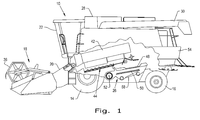
- FIG. 1 there is shown an agricultural harvester in the form of a combine 10, which generally includes a chassis 12, ground engaging wheels 14 and 16, header 18, feeder housing 20, operator cab 22, threshing and separating system 24, cleaning system 26, grain tank 28, and unloading auger 30.
- Front wheels 14 are larger flotation type wheels, and rear wheels 16 are smaller steerable wheels. Motive force is selectively applied to front wheels 14 through a power plant in the form of a diesel engine and a transmission (not shown).
- combine 10 is shown as including wheels, is also to be understood that combine 10 may include tracks, such as full tracks or half tracks.
- Header 18 is mounted to the front of combine 10 and includes a cutter bar (not shown) for severing crops from a field during forward motion of combine 10.
- a rotatable reel 36 feeds the crop into header 18, and a double auger (not shown) feeds the severed crop laterally inwardly from each side toward feeder housing 20.
- Feeder housing 20 conveys the cut crop to threshing and separating system 24, and is selectively vertically movable using appropriate actuators, such as hydraulic cylinders (not shown).
- Threshing and separating system 24 is of the axial-flow type, and generally includes a rotor at least partially enclosed by and rotatable within a corresponding perforated concave 42.
- the cut crops are threshed and separated by the rotation of rotor within concave 42, and larger elements, such as stalks, leaves and the like are discharged from the rear of combine 10.
- Smaller elements of crop material including grain and non-grain crop material, including particles lighter than grain, such as chaff, dust and straw, are discharged through perforations of concave 42.
- Threshing and separating system 24 can also be a different type of system, such as a system with a transverse rotor rather than an axial rotor, etc.
- Grain which has been separated by the threshing and separating assembly 24 falls onto a grain pan 44 and is conveyed toward cleaning system 26.
- Cleaning system 26 includes an upper sieve 48 (also known as a chaffer sieve), a lower sieve 50 (also known as a cleaning sieve), and a cleaning fan 52. Grain on sieves 48 and 50 is subjected to a cleaning action by fan 52 which provides an air flow through the sieves to remove chaff and other impurities such as dust from the grain by making this material airborne for discharge from straw hood 54 of combine 10.
- Grain pan 44 transports the grain and finer non-grain crop material to the upper surface of upper sieve 48.
- Upper sieve 48 and lower sieve 50 are vertically arranged relative to each other, and likewise oscillate in a fore-to-aft manner to spread the grain across sieves 48, 50, while permitting the passage of cleaned grain by gravity through the openings of sieves 48, 50.
- Clean grain passes through each sieve 48, 50 and from bottom pan 58 of cleaning system 26.
- the grain is passed laterally by an auger 52 to a generally vertically arranged grain elevator (not shown) for transport to grain tank 28.
- a pair of grain tank augers (not shown) at the bottom of grain tank 28 convey the clean grain laterally within grain tank 28 to unloading auger 30 for discharge from combine 10.
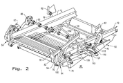
- the upper sieve 48 includes a left rail or frame 70 and a right rail or frame 72 interconnected by at least one cross frame 74.
- the left and right frames 70 and 72 are supported at the cross frame 74 by a front pivot support 76.
- a flexible rear link 78 connects to a rear support to maintain the rear of the rails in place.
- Support frames 82 provide a base affixed to the chassis 12 to provide ultimate support for the sieve 48.
- a sieve extends between right and left frames 70 and 72 to provide a surface for carrying material in an aft direction and permit grain or other crop material to drop through and be collected. The sieve is not shown to enable a clearer description of the present invention.
- the front of the right and left frames 70 and 72 are mounted for fore and aft movement through a fore and aft oscillation mechanism generally indicated at 84.
- An input drive shaft 86 extending transverse in chassis 12 receives a suitable power input for rotation. Both ends of drive shaft drive 86 reciprocate arm 88 through an eccentric mounting 90.
- Arm 88 connects to a first member 92 through a pivotal connection 96.
- a pivotal mounting 98 supported by frame 82 mounts the first member 92 and a second member 94 adjacent to it in radially inward from the first member 92.
- a frame interconnection 100 connects the first and second members 92 and 94.
- the second member 94 has a plurality of flexible rubber bushings 102 as shown particularly in Fig. 4 .
- a plurality of rubber bushings 104 enables an interconnection between the first and second members 92 and 94.
- the pivotal connections 76 (second member 94), common pivotal interconnections 98, 100 and pivotal connection 96 (first member 92) form triangles with two sides common and the third independent.
- the members 92 and 94 are formed generally as legs 93 and 95 connecting the pivotal mounting points, with one of the legs 95 being curved for clearance purposes. Webs 97 structurally reinforce the legs of member 94.
- members 92 and 94 are cast.
- a pivotal connection 106 on first member 92 through legs 107 connects with a link 108 that drives the lower sieve 50 for reciprocating movement. Details of this arrangement are not included to enable a better focus on the invention.
- the right and left frames 70 and 72 are selectively reciprocated from side to side by a side shaker mechanism generally indicated at 110.
- the mechanism includes a reciprocating electric actuator 112 appropriately mounted to frame 82 and having an output shaft 114 connecting to upper and lower links 116 by a pivotal input connection 118.
- the upper and lower links 116 are pivotally connected to the frame 82 at 120.
- a bushing 122, integral with a connecting rod 124 connects the links 116.
- the connecting rod 124 extends to a structural connection, (not shown) for tying the right frame 72 and left frame 70 together for side to side movement.
- the members 92 and 94 are preferably castings with the structural mounting points interconnected by legs of a triangle for producing a robust interconnection having a minimum of weight.
- the webs 97 in the second member 94 provide additional structural integrity with a minimum of additional weight.
Landscapes
- Life Sciences & Earth Sciences (AREA)
- Environmental Sciences (AREA)
- Threshing Machine Elements (AREA)
Abstract
Description
- The present invention relates to agricultural harvesters such as combines, and, more particularly, to sieves incorporated in the harvester crop processing section.
- An agricultural harvester known as a "combine" is historically termed such because it combines multiple harvesting functions with a single harvesting unit, such as picking, threshing, separating and cleaning. A combine includes a header which removes the crop from a field, and a feeder housing which transports the crop matter into a threshing rotor. The threshing rotor rotates within a perforated housing, which may be in the form of adjustable concaves, and performs a threshing operation on the crop to remove the grain. Once the grain is threshed it falls through perforations in the concaves and is transported to a grain pan. From the grain pan the grain is cleaned using a cleaning system, and is then transported to a grain tank onboard the combine. The cleaning system includes a cleaning fan which blows air through oscillating sieves to discharge chaff and other debris toward the rear of the combine. Non-grain crop material such as straw from the threshing section proceeds through a straw chopper and out the rear of the combine. When the grain tank becomes full, the combine is positioned adjacent a vehicle into which the grain is to be unloaded, such as a semi-trailer, gravity box, straight truck, or the like; and an unloading system on the combine is actuated to transfer the grain into the vehicle.
- More particularly, a rotary threshing or separating system includes one or more rotors which can extend axially (front to rear) or transversely within the body of the combine, and which are partially or fully surrounded by a perforated concave. The crop material is threshed and separated by the rotation of the rotor within the concave. Coarser non-grain crop material such as stalks and leaves are transported to the rear of the combine and discharged back to the field. The separated grain, together with some finer non-grain crop material such as chaff, dust, straw, and other crop residue are discharged through the concaves and fall onto the grain pan where they are transported to the cleaning system. Alternatively, the grain and finer non-grain crop material may also fall directly onto the cleaning system itself.
- The cleaning system further separates the grain from non-grain crop material, and typically includes a fan directing an air flow stream upwardly and rearwardly through vertically arranged sieves which oscillate in a fore and aft manner. The air flow stream lifts and carries the lighter non-grain crop material towards the rear end of the combine for discharge to the field. Clean grain, being heavier, and larger pieces of non-grain crop material, which are not carried away by the air flow stream, fall onto a surface of an upper sieve (also known as a chaffer sieve) where some or all of the clean grain passes through to a lower sieve (also known as a cleaning sieve). Grain and non-grain crop material remaining on the upper and lower sieves are physically separated by the reciprocating action of the sieves as the material moves rearwardly. Any grain and/or non-grain crop material remaining on the top surface of the upper sieve or sieve are discharged at the rear of the combine. Grain falling through the lower sieve lands on a bottom pan of the cleaning system, where it is conveyed forwardly toward a clean grain auger.
- The clean grain auger is positioned below the lower sieve, and receives clean grain from each sieve and from the bottom pan of the cleaning system. The clean grain auger then augers the clean grain laterally sideways to a clean grain elevator, which in turn conveys the clean grain to a grain tank onboard the combine.
- The upper sieve is driven for fore and aft movement to move the harvested crop material in an aft direction but at the same time separate the remaining grain or crop from the non-crop material. The sieve presents a significant weight having inertia forces that require structurally strong supports to secure the sieve in the agricultural frame but at the same time enable driven fore and aft movement. A further complication arises in that, when the agricultural harvester is on the side of a slope, it requires side to side movement of the sieve so as to prevent clogging of the material and resultant reduction in efficiency. The side to side movement is used generally selectively so that the continuous primary movement is fore and aft but the structural connection must also permit side to side movement of the sieve.
- Accordingly, what is needed in the art is a sieve support that is structurally sound to drive the sieve in a fore and aft oscillation and at the same time permit side to side movement of the pan.
- The present invention seeks to support a sieve in a structurally sound manner and allow it to be driven in a fore and aft direction but at the same time permit side to side movement.
- In one form, the invention is a sieve for an agricultural harvester. The sieve includes a right frame and a left frame interconnected by at least one cross frame. Supports are provided for one of the forward and rear ends of said right and left frames with the supports formed from first and second members having triangularly positioned mounting points, the first and second members being interconnected at two of the mounting points. The third mounting point on the first member is pivotally mounted to a fore and aft drive input for the sieve and the third mounting point for the second frame is pivotally mounted to the frames for driving fore and aft movement and permitting side to side movement. Supports are provided for said right and left frames at the end opposite the first and second members, permitting fore and aft movement and side to side movement
- In another form, the invention is an agricultural harvester with a main frame, a plurality of wheels for ground movement and grain processing equipment mounted in the frame. A sieve receives material from the grain processing equipment and includes a right frame and a left frame interconnected by a cross frame with the cross frame being positioned at the forward end of the right and left frames. Supports are provided for one of the forward and rear ends of said right and left frames with the supports formed from first and second members having triangularly positioned mounting points, the first and second members being interconnected at two of the mounting points. The third mounting point on the first member is pivotally mounted to a fore and aft drive input for the sieve and the third mounting point for the second frame is pivotally mounted to the frames for driving fore and aft movement and permitting side to side movement. Supports are provided for said right and left frames at the end opposite the first and second members, permitting fore and aft movement and side to side movement.
- An advantage of the present invention is a structurally robust support for a sieve that drives fore and aft movement and permits side to side movement.
- Another advantage of the present invention is a simplified structural interconnection for a sieve.
- The above-mentioned and other features and advantages of this invention, and the manner of attaining them, will become more apparent and the invention will be better understood by reference to the following description of an embodiment of the invention taken in conjunction with the accompanying drawings, wherein:
-
Fig. 1 is a side view of an embodiment of an agricultural harvester in the form of a combine which may include a sieve of the present invention; -
Fig. 2 is a perspective view of a sieve embodying the present invention; -
Fig. 3 is a side view of the sieve ofFig. 2 ; and -
Fig. 4 is a detailed view of a support frame for the sieve ofFigs. 2 and3 . - Corresponding reference characters indicate corresponding parts throughout the several views. The exemplification set out herein illustrates an embodiment of the invention, in one form, and such exemplification is not to be construed as limiting the scope of the invention in any manner.
- The terms "grain", "straw" and "tailings" are used principally throughout this specification for convenience but it is to be understood that these terms are not intended to be limiting. Thus "grain" refers to that part of the crop material which is threshed and separated from the discardable part of the crop material, which is referred to as non-grain crop material, MOG or straw. Incompletely threshed crop material is referred to as "tailings". Also the terms "forward", "rearward", "left" and "right", when used in connection with the agricultural harvester and/or components thereof are usually determined with reference to the direction of forward operative travel of the harvester, but again, they should not be construed as limiting. The terms "longitudinal" and "transverse" are determined with reference to the fore-and-aft direction of the agricultural harvester and are equally not to be construed as limiting.
- Referring now to the drawings, and more particularly to
Fig. 1 , there is shown an agricultural harvester in the form of acombine 10, which generally includes a chassis 12, groundengaging wheels header 18,feeder housing 20,operator cab 22, threshing and separating system 24,cleaning system 26,grain tank 28, andunloading auger 30. -
Front wheels 14 are larger flotation type wheels, andrear wheels 16 are smaller steerable wheels. Motive force is selectively applied tofront wheels 14 through a power plant in the form of a diesel engine and a transmission (not shown). Althoughcombine 10 is shown as including wheels, is also to be understood that combine 10 may include tracks, such as full tracks or half tracks. -
Header 18 is mounted to the front ofcombine 10 and includes a cutter bar (not shown) for severing crops from a field during forward motion ofcombine 10. Arotatable reel 36 feeds the crop intoheader 18, and a double auger (not shown) feeds the severed crop laterally inwardly from each side towardfeeder housing 20.Feeder housing 20 conveys the cut crop to threshing and separating system 24, and is selectively vertically movable using appropriate actuators, such as hydraulic cylinders (not shown). - Threshing and separating system 24 is of the axial-flow type, and generally includes a rotor at least partially enclosed by and rotatable within a corresponding perforated concave 42. The cut crops are threshed and separated by the rotation of rotor within concave 42, and larger elements, such as stalks, leaves and the like are discharged from the rear of
combine 10. Smaller elements of crop material including grain and non-grain crop material, including particles lighter than grain, such as chaff, dust and straw, are discharged through perforations of concave 42. Threshing and separating system 24 can also be a different type of system, such as a system with a transverse rotor rather than an axial rotor, etc. - Grain which has been separated by the threshing and separating assembly 24 falls onto a
grain pan 44 and is conveyed towardcleaning system 26.Cleaning system 26 includes an upper sieve 48 (also known as a chaffer sieve), a lower sieve 50 (also known as a cleaning sieve), and a cleaningfan 52. Grain onsieves fan 52 which provides an air flow through the sieves to remove chaff and other impurities such as dust from the grain by making this material airborne for discharge fromstraw hood 54 ofcombine 10.Grain pan 44 transports the grain and finer non-grain crop material to the upper surface ofupper sieve 48.Upper sieve 48 andlower sieve 50 are vertically arranged relative to each other, and likewise oscillate in a fore-to-aft manner to spread the grain acrosssieves sieves - Clean grain passes through each
sieve bottom pan 58 of cleaningsystem 26. The grain is passed laterally by anauger 52 to a generally vertically arranged grain elevator (not shown) for transport tograin tank 28. A pair of grain tank augers (not shown) at the bottom ofgrain tank 28 convey the clean grain laterally withingrain tank 28 to unloadingauger 30 for discharge fromcombine 10. - Referring now to
Fig. 2 , the upper andlower sieves upper sieve 48 includes a left rail orframe 70 and a right rail orframe 72 interconnected by at least onecross frame 74. The left andright frames cross frame 74 by afront pivot support 76. A flexiblerear link 78 connects to a rear support to maintain the rear of the rails in place. Support frames 82 provide a base affixed to the chassis 12 to provide ultimate support for thesieve 48. A sieve extends between right and leftframes - The front of the right and left
frames input drive shaft 86 extending transverse in chassis 12 receives a suitable power input for rotation. Both ends ofdrive shaft drive 86reciprocate arm 88 through an eccentric mounting 90.Arm 88 connects to afirst member 92 through apivotal connection 96. A pivotal mounting 98 supported byframe 82 mounts thefirst member 92 and asecond member 94 adjacent to it in radially inward from thefirst member 92. Aframe interconnection 100 connects the first andsecond members second member 94 has a plurality offlexible rubber bushings 102 as shown particularly inFig. 4 . A plurality ofrubber bushings 104, particularly shown inFig. 3 , enables an interconnection between the first andsecond members Figs 2 ,3 and4 , the pivotal connections 76 (second member 94), commonpivotal interconnections members legs 93 and 95 connecting the pivotal mounting points, with one of the legs 95 being curved for clearance purposes.Webs 97 structurally reinforce the legs ofmember 94. Preferably,members - A
pivotal connection 106 onfirst member 92 through legs 107 (Fig. 3 ) connects with alink 108 that drives thelower sieve 50 for reciprocating movement. Details of this arrangement are not included to enable a better focus on the invention. - The right and left
frames electric actuator 112 appropriately mounted to frame 82 and having anoutput shaft 114 connecting to upper andlower links 116 by apivotal input connection 118. The upper andlower links 116 are pivotally connected to theframe 82 at 120. Abushing 122, integral with a connectingrod 124 connects thelinks 116. The connectingrod 124 extends to a structural connection, (not shown) for tying theright frame 72 and leftframe 70 together for side to side movement. - The
members webs 97 in thesecond member 94 provide additional structural integrity with a minimum of additional weight. By interconnecting themembers pivotal support 98 for the first andsecond members mainframe elements 82 and the front pivotal support for the right and left side frames behind, sufficient side to side movement is permitted without a bulky overall envelope for the forward sieve support. The mechanism also permits a minimum width to allow a maximum width for the sieve enabling efficient processing of the grain. Therubber bushings second members
Claims (12)
- A sieve (48, 50) for an agricultural harvester, said sieve (48, 50) comprising:a right frame (72) and a left frame (70) interconnected by at least one cross frame (74);supports (76) for one of the forward and rear ends of said right and left frames (72, 70), said supports (76) comprising first and second members (92, 94) having triangularly positioned mounting points (96, 98, 100 ), the first and second members (92, 94) being interconnected at two of the mounting points(98, 100), the third mounting point (98) on said first member (92) being pivotally mounted to a support (82) for said sieve (48, 50), and the third mounting point (76) for said second member (94) being pivotally mounted to said right and left frames (72, 70) for driving fore and aft movement and permitting side to side movement; and,supports (78) for said right and left frames (72, 70) at the end opposite the first and second members (92, 94), permitting fore and aft movement and side to side movement.
- The sieve (48, 50) as claimed in claim 1, further comprising rubber bushings (102) interconnecting said first and second members (92, 94) at least at the two mounting points (989, 100) mutually interconnecting the members (92, 94).
- The sieve (48, 50) as claimed in claim 1, wherein said second member (94) is connected to said right and left frames (72, 70) at the cross frame (74).
- The sieve (48, 50) as claimed in claim 1, wherein said first and second members (92, 94) are at least partially formed from legs of a triangle interconnecting said triangular mounting points (96, 98, 100 ).
- The sieve (48, 50) as claimed in claim 4, wherein said first and second members (92, 94) are cast.
- The sieve (48, 50) as claimed in claim 5, wherein said second member (94) has integral structural webs (97) reinforcing said triangular legs.
- The sieve (48, 50) as claimed in claim 4, wherein said first member (92) has a further support point (106) for driving a mechanism for reciprocating movement.
- The sieve (48, 50) as claimed in claim 7, wherein said further support comprises legs (107) of a triangle.
- The sieve (48, 50) as claimed in claim 1, wherein the common mounting points (98, 100) for said first and second members (92, 94) are forward of said third mounting points (76, 96).
- An agricultural harvester (10) having a chassis (12), a plurality of mobile wheels (14, 16) for ground movement and grain processing equipment (24, 26) mounted in said chassis (12) and including a main sieve (48) for movement of chaff to a discharge end according to any one of the preceding claims.
- The agricultural harvester (10) as claimed in claim 10, further comprising a mechanism (84) supported by said chassis (12) for driving the first member (92) of said supports into fore and aft oscillation.
- The agricultural harvester (10) as claimed in claim 11, wherein said oscillating mechanism (84) comprises a link (88) connected to said third mounting point (96) on said first member (92) and an eccentric mechanism (90) for driving said link (88) in a fore and aft direction.
Applications Claiming Priority (1)
| Application Number | Priority Date | Filing Date | Title |
|---|---|---|---|
| US201562196083P | 2015-07-23 | 2015-07-23 |
Publications (2)
| Publication Number | Publication Date |
|---|---|
| EP3120686A1 true EP3120686A1 (en) | 2017-01-25 |
| EP3120686B1 EP3120686B1 (en) | 2019-06-26 |
Family
ID=56550119
Family Applications (1)
| Application Number | Title | Priority Date | Filing Date |
|---|---|---|---|
| EP16181011.4A Active EP3120686B1 (en) | 2015-07-23 | 2016-07-25 | Linkage for agricultural harvester cleaner |
Country Status (3)
| Country | Link |
|---|---|
| US (1) | US10104839B2 (en) |
| EP (1) | EP3120686B1 (en) |
| BR (1) | BR102016017211B1 (en) |
Cited By (1)
| Publication number | Priority date | Publication date | Assignee | Title |
|---|---|---|---|---|
| CN108144846A (en) * | 2017-12-22 | 2018-06-12 | 东北农业大学 | Watch regulating mechanism in grain cleaning double deck screen vertical equity inclination angle |
Families Citing this family (2)
| Publication number | Priority date | Publication date | Assignee | Title |
|---|---|---|---|---|
| DE102019125489A1 (en) * | 2019-09-23 | 2021-03-25 | Claas Selbstfahrende Erntemaschinen Gmbh | Pivoting device for the even distribution of goods on a conveying and cleaning element |
| EP4552474A1 (en) * | 2023-11-10 | 2025-05-14 | CNH Industrial Belgium N.V. | Grain cleaning system with side-shake |
Citations (3)
| Publication number | Priority date | Publication date | Assignee | Title |
|---|---|---|---|---|
| GB2146218A (en) * | 1983-09-10 | 1985-04-17 | Claas Ohg | Reciprocating sieve cleaning apparatus |
| EP1609352A1 (en) * | 2004-06-22 | 2005-12-28 | CNH Belgium N.V. | Grain cleaning system for a combine harvester. |
| EP2145530A2 (en) * | 2008-07-16 | 2010-01-20 | Deere & Company | Grain cleaning assembly |
Family Cites Families (18)
| Publication number | Priority date | Publication date | Assignee | Title |
|---|---|---|---|---|
| US2939581A (en) * | 1956-08-16 | 1960-06-07 | Massey Ferguson Inc | Combine cleaning shoe |
| DE3008385C2 (en) * | 1980-03-05 | 1985-07-18 | Claas Ohg, 4834 Harsewinkel | Device for distributing material to be sieved |
| US4770190A (en) * | 1987-05-15 | 1988-09-13 | Deere & Company | Cleaning shoe screen for an agricultural combine having readily replaceable louvers |
| AUPQ931100A0 (en) * | 2000-08-09 | 2000-08-31 | Ludowici Mineral Processing Equipment Pty Ltd | Screening apparatus |
| US6672957B2 (en) * | 2002-03-28 | 2004-01-06 | Agco Corporation | Combine harvester cleaning apparatus |
| BE1016486A4 (en) * | 2005-04-08 | 2006-12-05 | Wiele Michel Van De Nv | JACQUARD DEVICE. |
| US20080004092A1 (en) * | 2006-06-30 | 2008-01-03 | Deere & Company, A Delaware Corporation | Remote sieve or chaffer adjustment |
| GB2450483A (en) * | 2007-06-25 | 2008-12-31 | Cnh Belgium Nv | A Grain cleaning system for a combine harvester |
| US8118649B1 (en) * | 2010-09-01 | 2012-02-21 | Cnh America Llc | Grain distribution sensor and control |
| US8821229B2 (en) * | 2012-12-06 | 2014-09-02 | Cnh Industrial America Llc | Grain cleaning system for an agricultural combine |
| US8939829B2 (en) * | 2012-12-14 | 2015-01-27 | Cnh Industrial America Llc | Combine linear side-shake cleaning control system |
| US8951105B2 (en) | 2012-12-21 | 2015-02-10 | Cnh Industrial America Llc | Combine side-shake control system slider joint |
| BE1021136B1 (en) * | 2013-03-12 | 2016-02-22 | Cnh Industrial Belgium Nv | CUTTER WITH ADJUSTABLE CLEANING SHOE SET-UP |
| US9198359B2 (en) * | 2013-09-20 | 2015-12-01 | Deere & Company | Frame for a reciprocating sieve |
| US9258945B2 (en) * | 2013-09-20 | 2016-02-16 | Deere & Company | Hanger mount for a reciprocating sieve |
| BE1022310B1 (en) | 2014-04-22 | 2016-03-15 | Cnh Industrial Belgium Nv | CUTTERS |
| BE1021870B1 (en) | 2014-04-22 | 2016-01-22 | Cnh Industrial Belgium Nv | DRIVE WITH A VARIABLE BATTLE FOR A CLEANING SYSTEM IN A HARVESTING MACHINE. |
| BE1021871B1 (en) | 2014-04-23 | 2016-01-22 | Cnh Industrial Belgium Nv | CUTTERS. |
-
2016
- 2016-07-25 US US15/218,187 patent/US10104839B2/en active Active
- 2016-07-25 EP EP16181011.4A patent/EP3120686B1/en active Active
- 2016-07-25 BR BR102016017211-0A patent/BR102016017211B1/en active IP Right Grant
Patent Citations (3)
| Publication number | Priority date | Publication date | Assignee | Title |
|---|---|---|---|---|
| GB2146218A (en) * | 1983-09-10 | 1985-04-17 | Claas Ohg | Reciprocating sieve cleaning apparatus |
| EP1609352A1 (en) * | 2004-06-22 | 2005-12-28 | CNH Belgium N.V. | Grain cleaning system for a combine harvester. |
| EP2145530A2 (en) * | 2008-07-16 | 2010-01-20 | Deere & Company | Grain cleaning assembly |
Cited By (1)
| Publication number | Priority date | Publication date | Assignee | Title |
|---|---|---|---|---|
| CN108144846A (en) * | 2017-12-22 | 2018-06-12 | 东北农业大学 | Watch regulating mechanism in grain cleaning double deck screen vertical equity inclination angle |
Also Published As
| Publication number | Publication date |
|---|---|
| BR102016017211A2 (en) | 2017-01-31 |
| EP3120686B1 (en) | 2019-06-26 |
| BR102016017211B1 (en) | 2021-08-24 |
| US10104839B2 (en) | 2018-10-23 |
| US20170020073A1 (en) | 2017-01-26 |
Similar Documents
| Publication | Publication Date | Title |
|---|---|---|
| US9992924B2 (en) | Folding mechanism for wide wheat headers | |
| EP2663175B1 (en) | Combine harvester grain cleaning apparatus | |
| EP3120687B1 (en) | Side shaker link for agricultural harvester sieve assembly | |
| US11723309B2 (en) | Side shake rate based on machine throughputs | |
| EP3172959A1 (en) | Chopper and spreader for an agricultural harvester | |
| EP3207787A1 (en) | Agricultural harvester concave adjustment system | |
| EP3092891A1 (en) | Chopper for an agricultural harvester | |
| EP3275304B1 (en) | Lateral shake mechanism for agricultural harvester cleaner | |
| US10080330B2 (en) | Variable amount of side shake based on user inputs | |
| EP3120685B1 (en) | Sieve arrangements for a cleaning system in an agricultural harvester | |
| EP3132670B1 (en) | Side shake rate based on machine throughputs | |
| US10398085B2 (en) | Drive arm for agricultural harvester | |
| US10123486B2 (en) | Frame for agricultural harvester cleaner | |
| EP3120686B1 (en) | Linkage for agricultural harvester cleaner | |
| EP2996457B1 (en) | Cover plate for a clean grain auger in a cleaning system of an agricultural harvester | |
| US10058036B2 (en) | Structural members for a side shaking sieve arrangement in an agricultural harvester |
Legal Events
| Date | Code | Title | Description |
|---|---|---|---|
| PUAI | Public reference made under article 153(3) epc to a published international application that has entered the european phase |
Free format text: ORIGINAL CODE: 0009012 |
|
| STAA | Information on the status of an ep patent application or granted ep patent |
Free format text: STATUS: THE APPLICATION HAS BEEN PUBLISHED |
|
| AK | Designated contracting states |
Kind code of ref document: A1 Designated state(s): AL AT BE BG CH CY CZ DE DK EE ES FI FR GB GR HR HU IE IS IT LI LT LU LV MC MK MT NL NO PL PT RO RS SE SI SK SM TR |
|
| AX | Request for extension of the european patent |
Extension state: BA ME |
|
| STAA | Information on the status of an ep patent application or granted ep patent |
Free format text: STATUS: REQUEST FOR EXAMINATION WAS MADE |
|
| 17P | Request for examination filed |
Effective date: 20170725 |
|
| RBV | Designated contracting states (corrected) |
Designated state(s): AL AT BE BG CH CY CZ DE DK EE ES FI FR GB GR HR HU IE IS IT LI LT LU LV MC MK MT NL NO PL PT RO RS SE SI SK SM TR |
|
| STAA | Information on the status of an ep patent application or granted ep patent |
Free format text: STATUS: EXAMINATION IS IN PROGRESS |
|
| 17Q | First examination report despatched |
Effective date: 20180424 |
|
| GRAP | Despatch of communication of intention to grant a patent |
Free format text: ORIGINAL CODE: EPIDOSNIGR1 |
|
| STAA | Information on the status of an ep patent application or granted ep patent |
Free format text: STATUS: GRANT OF PATENT IS INTENDED |
|
| INTG | Intention to grant announced |
Effective date: 20190116 |
|
| GRAS | Grant fee paid |
Free format text: ORIGINAL CODE: EPIDOSNIGR3 |
|
| GRAA | (expected) grant |
Free format text: ORIGINAL CODE: 0009210 |
|
| STAA | Information on the status of an ep patent application or granted ep patent |
Free format text: STATUS: THE PATENT HAS BEEN GRANTED |
|
| AK | Designated contracting states |
Kind code of ref document: B1 Designated state(s): AL AT BE BG CH CY CZ DE DK EE ES FI FR GB GR HR HU IE IS IT LI LT LU LV MC MK MT NL NO PL PT RO RS SE SI SK SM TR |
|
| REG | Reference to a national code |
Ref country code: GB Ref legal event code: FG4D |
|
| REG | Reference to a national code |
Ref country code: CH Ref legal event code: EP |
|
| REG | Reference to a national code |
Ref country code: AT Ref legal event code: REF Ref document number: 1147217 Country of ref document: AT Kind code of ref document: T Effective date: 20190715 |
|
| REG | Reference to a national code |
Ref country code: DE Ref legal event code: R096 Ref document number: 602016015812 Country of ref document: DE |
|
| REG | Reference to a national code |
Ref country code: IE Ref legal event code: FG4D |
|
| REG | Reference to a national code |
Ref country code: NL Ref legal event code: MP Effective date: 20190626 |
|
| PG25 | Lapsed in a contracting state [announced via postgrant information from national office to epo] |
Ref country code: AL Free format text: LAPSE BECAUSE OF FAILURE TO SUBMIT A TRANSLATION OF THE DESCRIPTION OR TO PAY THE FEE WITHIN THE PRESCRIBED TIME-LIMIT Effective date: 20190626 Ref country code: NO Free format text: LAPSE BECAUSE OF FAILURE TO SUBMIT A TRANSLATION OF THE DESCRIPTION OR TO PAY THE FEE WITHIN THE PRESCRIBED TIME-LIMIT Effective date: 20190926 Ref country code: FI Free format text: LAPSE BECAUSE OF FAILURE TO SUBMIT A TRANSLATION OF THE DESCRIPTION OR TO PAY THE FEE WITHIN THE PRESCRIBED TIME-LIMIT Effective date: 20190626 Ref country code: SE Free format text: LAPSE BECAUSE OF FAILURE TO SUBMIT A TRANSLATION OF THE DESCRIPTION OR TO PAY THE FEE WITHIN THE PRESCRIBED TIME-LIMIT Effective date: 20190626 Ref country code: HR Free format text: LAPSE BECAUSE OF FAILURE TO SUBMIT A TRANSLATION OF THE DESCRIPTION OR TO PAY THE FEE WITHIN THE PRESCRIBED TIME-LIMIT Effective date: 20190626 Ref country code: LT Free format text: LAPSE BECAUSE OF FAILURE TO SUBMIT A TRANSLATION OF THE DESCRIPTION OR TO PAY THE FEE WITHIN THE PRESCRIBED TIME-LIMIT Effective date: 20190626 |
|
| REG | Reference to a national code |
Ref country code: LT Ref legal event code: MG4D |
|
| PG25 | Lapsed in a contracting state [announced via postgrant information from national office to epo] |
Ref country code: GR Free format text: LAPSE BECAUSE OF FAILURE TO SUBMIT A TRANSLATION OF THE DESCRIPTION OR TO PAY THE FEE WITHIN THE PRESCRIBED TIME-LIMIT Effective date: 20190927 Ref country code: BG Free format text: LAPSE BECAUSE OF FAILURE TO SUBMIT A TRANSLATION OF THE DESCRIPTION OR TO PAY THE FEE WITHIN THE PRESCRIBED TIME-LIMIT Effective date: 20190926 Ref country code: RS Free format text: LAPSE BECAUSE OF FAILURE TO SUBMIT A TRANSLATION OF THE DESCRIPTION OR TO PAY THE FEE WITHIN THE PRESCRIBED TIME-LIMIT Effective date: 20190626 Ref country code: LV Free format text: LAPSE BECAUSE OF FAILURE TO SUBMIT A TRANSLATION OF THE DESCRIPTION OR TO PAY THE FEE WITHIN THE PRESCRIBED TIME-LIMIT Effective date: 20190626 |
|
| REG | Reference to a national code |
Ref country code: AT Ref legal event code: MK05 Ref document number: 1147217 Country of ref document: AT Kind code of ref document: T Effective date: 20190626 |
|
| PG25 | Lapsed in a contracting state [announced via postgrant information from national office to epo] |
Ref country code: RO Free format text: LAPSE BECAUSE OF FAILURE TO SUBMIT A TRANSLATION OF THE DESCRIPTION OR TO PAY THE FEE WITHIN THE PRESCRIBED TIME-LIMIT Effective date: 20190626 Ref country code: CZ Free format text: LAPSE BECAUSE OF FAILURE TO SUBMIT A TRANSLATION OF THE DESCRIPTION OR TO PAY THE FEE WITHIN THE PRESCRIBED TIME-LIMIT Effective date: 20190626 Ref country code: EE Free format text: LAPSE BECAUSE OF FAILURE TO SUBMIT A TRANSLATION OF THE DESCRIPTION OR TO PAY THE FEE WITHIN THE PRESCRIBED TIME-LIMIT Effective date: 20190626 Ref country code: AT Free format text: LAPSE BECAUSE OF FAILURE TO SUBMIT A TRANSLATION OF THE DESCRIPTION OR TO PAY THE FEE WITHIN THE PRESCRIBED TIME-LIMIT Effective date: 20190626 Ref country code: NL Free format text: LAPSE BECAUSE OF FAILURE TO SUBMIT A TRANSLATION OF THE DESCRIPTION OR TO PAY THE FEE WITHIN THE PRESCRIBED TIME-LIMIT Effective date: 20190626 Ref country code: SK Free format text: LAPSE BECAUSE OF FAILURE TO SUBMIT A TRANSLATION OF THE DESCRIPTION OR TO PAY THE FEE WITHIN THE PRESCRIBED TIME-LIMIT Effective date: 20190626 Ref country code: PT Free format text: LAPSE BECAUSE OF FAILURE TO SUBMIT A TRANSLATION OF THE DESCRIPTION OR TO PAY THE FEE WITHIN THE PRESCRIBED TIME-LIMIT Effective date: 20191028 |
|
| PG25 | Lapsed in a contracting state [announced via postgrant information from national office to epo] |
Ref country code: IS Free format text: LAPSE BECAUSE OF FAILURE TO SUBMIT A TRANSLATION OF THE DESCRIPTION OR TO PAY THE FEE WITHIN THE PRESCRIBED TIME-LIMIT Effective date: 20191026 Ref country code: SM Free format text: LAPSE BECAUSE OF FAILURE TO SUBMIT A TRANSLATION OF THE DESCRIPTION OR TO PAY THE FEE WITHIN THE PRESCRIBED TIME-LIMIT Effective date: 20190626 Ref country code: ES Free format text: LAPSE BECAUSE OF FAILURE TO SUBMIT A TRANSLATION OF THE DESCRIPTION OR TO PAY THE FEE WITHIN THE PRESCRIBED TIME-LIMIT Effective date: 20190626 |
|
| REG | Reference to a national code |
Ref country code: CH Ref legal event code: PL |
|
| PG25 | Lapsed in a contracting state [announced via postgrant information from national office to epo] |
Ref country code: TR Free format text: LAPSE BECAUSE OF FAILURE TO SUBMIT A TRANSLATION OF THE DESCRIPTION OR TO PAY THE FEE WITHIN THE PRESCRIBED TIME-LIMIT Effective date: 20190626 Ref country code: MC Free format text: LAPSE BECAUSE OF FAILURE TO SUBMIT A TRANSLATION OF THE DESCRIPTION OR TO PAY THE FEE WITHIN THE PRESCRIBED TIME-LIMIT Effective date: 20190626 |
|
| REG | Reference to a national code |
Ref country code: BE Ref legal event code: MM Effective date: 20190731 |
|
| PG25 | Lapsed in a contracting state [announced via postgrant information from national office to epo] |
Ref country code: DK Free format text: LAPSE BECAUSE OF FAILURE TO SUBMIT A TRANSLATION OF THE DESCRIPTION OR TO PAY THE FEE WITHIN THE PRESCRIBED TIME-LIMIT Effective date: 20190626 Ref country code: PL Free format text: LAPSE BECAUSE OF FAILURE TO SUBMIT A TRANSLATION OF THE DESCRIPTION OR TO PAY THE FEE WITHIN THE PRESCRIBED TIME-LIMIT Effective date: 20190626 |
|
| PG25 | Lapsed in a contracting state [announced via postgrant information from national office to epo] |
Ref country code: LI Free format text: LAPSE BECAUSE OF NON-PAYMENT OF DUE FEES Effective date: 20190731 Ref country code: LU Free format text: LAPSE BECAUSE OF NON-PAYMENT OF DUE FEES Effective date: 20190725 Ref country code: BE Free format text: LAPSE BECAUSE OF NON-PAYMENT OF DUE FEES Effective date: 20190731 Ref country code: IS Free format text: LAPSE BECAUSE OF FAILURE TO SUBMIT A TRANSLATION OF THE DESCRIPTION OR TO PAY THE FEE WITHIN THE PRESCRIBED TIME-LIMIT Effective date: 20200224 Ref country code: CH Free format text: LAPSE BECAUSE OF NON-PAYMENT OF DUE FEES Effective date: 20190731 |
|
| REG | Reference to a national code |
Ref country code: DE Ref legal event code: R097 Ref document number: 602016015812 Country of ref document: DE |
|
| PLBE | No opposition filed within time limit |
Free format text: ORIGINAL CODE: 0009261 |
|
| STAA | Information on the status of an ep patent application or granted ep patent |
Free format text: STATUS: NO OPPOSITION FILED WITHIN TIME LIMIT |
|
| PG2D | Information on lapse in contracting state deleted |
Ref country code: IS |
|
| PG25 | Lapsed in a contracting state [announced via postgrant information from national office to epo] |
Ref country code: IE Free format text: LAPSE BECAUSE OF NON-PAYMENT OF DUE FEES Effective date: 20190725 |
|
| 26N | No opposition filed |
Effective date: 20200603 |
|
| PG25 | Lapsed in a contracting state [announced via postgrant information from national office to epo] |
Ref country code: SI Free format text: LAPSE BECAUSE OF FAILURE TO SUBMIT A TRANSLATION OF THE DESCRIPTION OR TO PAY THE FEE WITHIN THE PRESCRIBED TIME-LIMIT Effective date: 20190626 |
|
| PG25 | Lapsed in a contracting state [announced via postgrant information from national office to epo] |
Ref country code: CY Free format text: LAPSE BECAUSE OF FAILURE TO SUBMIT A TRANSLATION OF THE DESCRIPTION OR TO PAY THE FEE WITHIN THE PRESCRIBED TIME-LIMIT Effective date: 20190626 |
|
| REG | Reference to a national code |
Ref country code: DE Ref legal event code: R082 Ref document number: 602016015812 Country of ref document: DE Representative=s name: KROHER STROBEL RECHTS- UND PATENTANWAELTE PART, DE |
|
| PG25 | Lapsed in a contracting state [announced via postgrant information from national office to epo] |
Ref country code: MT Free format text: LAPSE BECAUSE OF FAILURE TO SUBMIT A TRANSLATION OF THE DESCRIPTION OR TO PAY THE FEE WITHIN THE PRESCRIBED TIME-LIMIT Effective date: 20190626 Ref country code: HU Free format text: LAPSE BECAUSE OF FAILURE TO SUBMIT A TRANSLATION OF THE DESCRIPTION OR TO PAY THE FEE WITHIN THE PRESCRIBED TIME-LIMIT; INVALID AB INITIO Effective date: 20160725 |
|
| PG25 | Lapsed in a contracting state [announced via postgrant information from national office to epo] |
Ref country code: MK Free format text: LAPSE BECAUSE OF FAILURE TO SUBMIT A TRANSLATION OF THE DESCRIPTION OR TO PAY THE FEE WITHIN THE PRESCRIBED TIME-LIMIT Effective date: 20190626 |
|
| PGFP | Annual fee paid to national office [announced via postgrant information from national office to epo] |
Ref country code: DE Payment date: 20250728 Year of fee payment: 10 |
|
| PGFP | Annual fee paid to national office [announced via postgrant information from national office to epo] |
Ref country code: IT Payment date: 20250721 Year of fee payment: 10 |
|
| PGFP | Annual fee paid to national office [announced via postgrant information from national office to epo] |
Ref country code: GB Payment date: 20250722 Year of fee payment: 10 |
|
| PGFP | Annual fee paid to national office [announced via postgrant information from national office to epo] |
Ref country code: FR Payment date: 20250725 Year of fee payment: 10 |