EP3120685A1 - Sieve arrangements for a cleaning system in an agricultural harvester - Google Patents
Sieve arrangements for a cleaning system in an agricultural harvester Download PDFInfo
- Publication number
- EP3120685A1 EP3120685A1 EP16181010.6A EP16181010A EP3120685A1 EP 3120685 A1 EP3120685 A1 EP 3120685A1 EP 16181010 A EP16181010 A EP 16181010A EP 3120685 A1 EP3120685 A1 EP 3120685A1
- Authority
- EP
- European Patent Office
- Prior art keywords
- sieve
- cleaning system
- grain
- frame
- chaffer
- Prior art date
- Legal status (The legal status is an assumption and is not a legal conclusion. Google has not performed a legal analysis and makes no representation as to the accuracy of the status listed.)
- Granted
Links
Images



Classifications
-
- A—HUMAN NECESSITIES
- A01—AGRICULTURE; FORESTRY; ANIMAL HUSBANDRY; HUNTING; TRAPPING; FISHING
- A01F—PROCESSING OF HARVESTED PRODUCE; HAY OR STRAW PRESSES; DEVICES FOR STORING AGRICULTURAL OR HORTICULTURAL PRODUCE
- A01F12/00—Parts or details of threshing apparatus
- A01F12/44—Grain cleaners; Grain separators
- A01F12/446—Sieving means
-
- A—HUMAN NECESSITIES
- A01—AGRICULTURE; FORESTRY; ANIMAL HUSBANDRY; HUNTING; TRAPPING; FISHING
- A01D—HARVESTING; MOWING
- A01D41/00—Combines, i.e. harvesters or mowers combined with threshing devices
- A01D41/12—Details of combines
Definitions
- the present invention relates to agricultural harvesters such as combines, and, more particularly, to cleaning systems used in such combines.
- a combine An agricultural harvester known as a "combine” is historically termed such because it combines multiple harvesting functions with a single harvesting unit, such as picking, threshing, separating and cleaning.
- a combine includes a header which removes the crop from a field, and a feeder housing which transports the crop matter into a threshing rotor.
- the threshing rotor rotates within a perforated housing, which may be in the form of adjustable concaves, and performs a threshing operation on the crop to remove the grain.
- Once the grain is threshed it falls through perforations in the concaves onto a grain pan. From the grain pan the grain is cleaned using a cleaning system, and is then transported to a grain tank onboard the combine.
- the cleaning system includes a cleaning fan which blows air through oscillating sieves to discharge chaff and other debris toward the rear of the combine.
- Non-grain crop material such as straw from the threshing section proceeds through a straw chopper and out the rear of the combine.
- the combine When the grain tank becomes full, the combine is positioned adjacent a vehicle into which the grain is to be unloaded, such as a semi-trailer, gravity box, straight truck, or the like; and an unloading system on the combine is actuated to transfer the grain into the vehicle.
- a rotary threshing or separating system includes one or more rotors which can extend axially (front to rear) or transversely within the body of the combine, and which are partially or fully surrounded by a perforated concave.
- the crop material is threshed and separated by the rotation of the rotor within the concave.
- Coarser non-grain crop material such as stalks and leaves are transported to the rear of the combine and discharged back to the field.
- the separated grain, together with some finer non-grain crop material such as chaff, dust, straw, and other crop residue are discharged through the concaves and fall onto the grain pan where they are transported to the cleaning system.
- the grain and finer non-grain crop material may also fall directly onto the cleaning system itself.
- the cleaning system further separates the grain from non-grain crop material, and typically includes a fan directing an air flow stream upwardly and rearwardly through vertically arranged sieves which oscillate in a fore and aft manner.
- the air flow stream lifts and carries the lighter non-grain crop material towards the rear end of the combine for discharge to the field.
- Grain and non-grain crop material remaining on the upper and lower sieves are physically separated by the reciprocating action of the sieves as the material moves rearwardly. Any grain and/or non-grain crop material remaining on the top surface of the upper sieve are discharged at the rear of the combine. Grain falling through the lower sieve lands on a bottom pan of the cleaning system, where it is conveyed forwardly toward a clean grain auger.
- the cleaning system can include a sieve which is mounted within a chaffer frame, and the chaffer frame is oscillated in a fore-to-aft direction to clean the grain.
- the sieve can be removable from the chaffer frame for cleaning and repair, but removal of the sieve can be difficult.
- What is needed in the art is a cleaning system with a sieve which can be more easily removed from and installed within a chaffer frame, and securely held in place during oscillations of the chaffer frame.
- the present invention provides a cleaning system with a chaffer frame having a clamp, and a sieve with an interference member which interacts with the clamp to guide the sieve into place within the chaffer frame, and hold the sieve within the chaffer frame.
- the invention in one form is directed to a cleaning system for an agricultural combine harvester, including a sieve having a periphery and an interference member located at the periphery.
- a chaffer frame carries the sieve, and includes a clamp with a pair of spring fingers positioned on either side of the interference member, thereby retaining the sieve within the chaffer frame.
- the invention in another form is directed to an agricultural combine harvester, including a chassis and a cleaning system carried by the chassis.
- the cleaning system includes a sieve having a periphery and an interference member located at the periphery.
- a chaffer frame carries the sieve, and includes a clamp with a pair of spring fingers positioned on either side of the interference member, thereby retaining the sieve within the chaffer frame.
- FIG. 1 there is shown an agricultural harvester in the form of a combine 10, which generally includes a chassis 12, ground engaging wheels 14 and 16, header 18, feeder housing 20, operator cab 22, threshing and separating system 24, cleaning system 26, grain tank 28, and unloading auger 30.
- Front wheels 14 are larger flotation type wheels, and rear wheels 16 are smaller steerable wheels. Motive force is selectively applied to front wheels 14 through a power plant in the form of a diesel engine 32 and a transmission (not shown).
- combine 10 is shown as including wheels, is also to be understood that combine 10 may include tracks, such as full tracks or half tracks.
- Header 18 is mounted to the front of combine 10 and includes a cutter bar 34 for severing crops from a field during forward motion of combine 10.
- a rotatable reel 36 feeds the crop into header 18, and a double auger 38 feeds the severed crop laterally inwardly from each side toward feeder housing 20.
- Feeder housing 20 conveys the cut crop to threshing and separating system 24, and is selectively vertically movable using appropriate actuators, such as hydraulic cylinders (not shown).
- Threshing and separating system 24 is of the axial-flow type, and generally includes a rotor 40 at least partially enclosed by and rotatable within a corresponding perforated concave 42.
- the cut crops are threshed and separated by the rotation of rotor 40 within concave 42, and larger elements, such as stalks, leaves and the like are discharged from the rear of combine 10.
- Smaller elements of crop material including grain and non-grain crop material, including particles lighter than grain, such as chaff, dust and straw, are discharged through perforations of concave 42.
- Threshing and separating system 24 can also be a different type of system, such as a system with a transverse rotor rather than an axial rotor, etc.
- Cleaning system 26 may include an optional pre-cleaning sieve 46, an upper sieve 48 (also known as a chaffer sieve), a lower sieve 50 (also known as a cleaning sieve), and a cleaning fan 52. Grain on sieves 46, 48 and 50 is subjected to a cleaning action by fan 52 which provides an air flow through the sieves to remove chaff and other impurities such as dust from the grain by making this material airborne for discharge from straw hood 54 of combine 10.
- Grain pan 44 and pre-cleaning sieve 46 oscillate in a fore-to-aft manner to transport the grain and finer non-grain crop material to the upper surface of upper sieve 48.
- Upper sieve 48 and lower sieve 50 are vertically arranged relative to each other, and likewise oscillate in a fore-to-aft manner to spread the grain across sieves 48, 50, while permitting the passage of cleaned grain by gravity through the openings of sieves 48, 50.
- Clean grain falls to a clean grain auger 56 positioned crosswise below and toward the front of lower sieve 50.
- Clean grain auger 56 receives clean grain from each sieve 48, 50 and from bottom pan 58 of cleaning system 26.
- Clean grain auger 56 conveys the clean grain laterally to a generally vertically arranged grain elevator 60 for transport to grain tank 28.
- Tailings from cleaning system 26 fall to a tailings auger trough 62.
- the tailings are transported via tailings auger 64 and return auger 66 to the upstream end of cleaning system 26 for repeated cleaning action.
- a pair of grain tank augers 68 at the bottom of grain tank 28 convey the clean grain laterally within grain tank 28 to unloading auger 30 for discharge from combine 10.
- a sieve arrangement 100 of the present invention including a sieve 102 which can be part of the cleaning system 26 shown in Fig. 1 , such as at a sieve location corresponding to sieves 46, 48 and/or 50.
- the sieve 102 has a periphery 108 and an interference member 110 located at the periphery108.
- the interference member 110 is in the form of a rectangular block which is mounted to and extends from a peripheral frame member 112 of the sieve 102.
- the interference member 110 could be differently configured, such as a disk shaped member, rod, etc.
- the chaffer frame 104 carries the sieve 102, and includes a pair of rails 106 upon which the sieve 102 rests.
- the sieve 102 can be loaded into the chaffer frame 104 as a cartridge.
- the chaffer frame 104 also includes a clamp 116 with a pair of spring fingers 118 positioned on either side of the interference member 110, thereby retaining the sieve 102 within the chaffer frame 104.
- the clamp 116 inhibits movement of the sieve 102 within the chaffer frame 104 in two axes.
- the spring loaded fingers 118 of the clamp 116 can also act as a guide to guide the sieve 102 into position within the chaffer frame 104 during loading.
- the spring fingers 118 can include a beveled end (not numbered, but shown, e.g., in Fig. 5 ) that assists in guiding the sieve into position within the chaffer frame.
- a sieve arrangement 120 of the present invention including a sieve 122 which can be part of the cleaning system 26 shown in Fig. 1 , such as at a sieve location corresponding to sieves 46, 48 and/or 50.
- the sieve arrangement 120 can oscillate back and forth at 4.5 Hz or higher. This subjects the sieve arrangement 120, including the sieves 122, to cyclical loads. Conventional sieves may not meet reliability goal with welded rear corner gussets and welded dividers due to the low allowable cyclical fatigue life of welds. In order to meet goals, allowable cyclical fatigue limits of welds would need to be approximately /-3.2 ksi or less. The allowable cyclical fatigue limit of non-welded joint is approximately /-12 ksi. By eliminating welds, the life expectancy of the sieve 122 is greatly improved.
- the sieves 122 are configured so rear corner gussets 124 and/or dividers 126 can be riveted using rivets 128.
- Rivets 128 are easy to install, and take the place of welded joints to increase the reliability. Each rivet 128 takes the place of at least one bolt and nut and/or welded connection. The rivets 128 are quicker to install than bolts and nuts. Additionally, no torquing of the joint is required, as is the case if a bolted connection was used.
- the sieve 122 can include a plurality of peripheral frame members 130, and a plurality of adjustable finger plates 132 mounted within the frame members 130. At least two of the frame members 130 are interconnected with each other via a gusset 124 and rivets 128.
- the peripheral frame members 130 can include a rear frame member 130A and a pair of side frame members 130B, with the rear frame member 130A being attached to each of the side frame members 130B via a respective gusset 124 and a plurality of rivets 128.
- the peripheral frame members 130 can also include a front frame member 130C.
- One or more dividers 134 can extend in a fore/aft direction between the front frame member 130C and the rear frame member 130A. Each divider 134 can be attached to the rear frame member 130A via a respective gusset 124 and a plurality of rivets 128.
- the rivets 128 are configured as standard rivets. However, the rivets 128 can also be configured as specially configured rivets, such as rivnuts.
Landscapes
- Life Sciences & Earth Sciences (AREA)
- Environmental Sciences (AREA)
- Threshing Machine Elements (AREA)
- Combined Means For Separation Of Solids (AREA)
Abstract
Description
- The present invention relates to agricultural harvesters such as combines, and, more particularly, to cleaning systems used in such combines.
- An agricultural harvester known as a "combine" is historically termed such because it combines multiple harvesting functions with a single harvesting unit, such as picking, threshing, separating and cleaning. A combine includes a header which removes the crop from a field, and a feeder housing which transports the crop matter into a threshing rotor. The threshing rotor rotates within a perforated housing, which may be in the form of adjustable concaves, and performs a threshing operation on the crop to remove the grain. Once the grain is threshed it falls through perforations in the concaves onto a grain pan. From the grain pan the grain is cleaned using a cleaning system, and is then transported to a grain tank onboard the combine. The cleaning system includes a cleaning fan which blows air through oscillating sieves to discharge chaff and other debris toward the rear of the combine. Non-grain crop material such as straw from the threshing section proceeds through a straw chopper and out the rear of the combine. When the grain tank becomes full, the combine is positioned adjacent a vehicle into which the grain is to be unloaded, such as a semi-trailer, gravity box, straight truck, or the like; and an unloading system on the combine is actuated to transfer the grain into the vehicle.
- More particularly, a rotary threshing or separating system includes one or more rotors which can extend axially (front to rear) or transversely within the body of the combine, and which are partially or fully surrounded by a perforated concave. The crop material is threshed and separated by the rotation of the rotor within the concave. Coarser non-grain crop material such as stalks and leaves are transported to the rear of the combine and discharged back to the field. The separated grain, together with some finer non-grain crop material such as chaff, dust, straw, and other crop residue are discharged through the concaves and fall onto the grain pan where they are transported to the cleaning system. Alternatively, the grain and finer non-grain crop material may also fall directly onto the cleaning system itself.
- The cleaning system further separates the grain from non-grain crop material, and typically includes a fan directing an air flow stream upwardly and rearwardly through vertically arranged sieves which oscillate in a fore and aft manner. The air flow stream lifts and carries the lighter non-grain crop material towards the rear end of the combine for discharge to the field. Clean grain, being heavier, and larger pieces of non-grain crop material, which are not carried away by the air flow stream, fall onto a surface of an upper sieve (also known as a chaffer sieve) where some or all of the clean grain passes through to a lower sieve (also known as a cleaning sieve). Grain and non-grain crop material remaining on the upper and lower sieves are physically separated by the reciprocating action of the sieves as the material moves rearwardly. Any grain and/or non-grain crop material remaining on the top surface of the upper sieve are discharged at the rear of the combine. Grain falling through the lower sieve lands on a bottom pan of the cleaning system, where it is conveyed forwardly toward a clean grain auger.
- The cleaning system can include a sieve which is mounted within a chaffer frame, and the chaffer frame is oscillated in a fore-to-aft direction to clean the grain. The sieve can be removable from the chaffer frame for cleaning and repair, but removal of the sieve can be difficult.
- What is needed in the art is a cleaning system with a sieve which can be more easily removed from and installed within a chaffer frame, and securely held in place during oscillations of the chaffer frame.
- The present invention provides a cleaning system with a chaffer frame having a clamp, and a sieve with an interference member which interacts with the clamp to guide the sieve into place within the chaffer frame, and hold the sieve within the chaffer frame.
- The invention in one form is directed to a cleaning system for an agricultural combine harvester, including a sieve having a periphery and an interference member located at the periphery. A chaffer frame carries the sieve, and includes a clamp with a pair of spring fingers positioned on either side of the interference member, thereby retaining the sieve within the chaffer frame.
- The invention in another form is directed to an agricultural combine harvester, including a chassis and a cleaning system carried by the chassis. The cleaning system includes a sieve having a periphery and an interference member located at the periphery. A chaffer frame carries the sieve, and includes a clamp with a pair of spring fingers positioned on either side of the interference member, thereby retaining the sieve within the chaffer frame.
- The above-mentioned and other features and advantages of this invention, and the manner of attaining them, will become more apparent and the invention will be better understood by reference to the following description of an embodiment of the invention taken in conjunction with the accompanying drawings, wherein:
-
Fig. 1 is a side view of an embodiment of an agricultural harvester in the form of a combine which may include sieve arrangements of the present invention; -
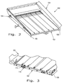
Fig. 2 is a perspective view of an embodiment of a sieve arrangement of the present invention; -
Fig. 3 is fragmented, perspective of the sieve arrangement shown inFig. 2 ; -
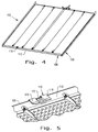
Fig. 4 is a perspective view of the sieve shown inFigs. 2 and 3 ; -
Fig. 5 is a fragmented, perspective view of the sieve shown inFig. 4 ; -
Fig. 6 is another fragmented, perspective view of the sieve shown inFigs. 4 and 5 ; -
Fig. 7 is a fragmented, perspective view of another embodiment of a sieve of the present invention; -
Fig. 8 is another fragmented, perspective view of the sieve shown inFig. 7 ; and -
Fig. 9 is another fragmented, perspective view of the sieve shown inFigs. 7 and8 . - Corresponding reference characters indicate corresponding parts throughout the several views. The exemplification set out herein illustrates an embodiment of the invention, in one form, and such exemplification is not to be construed as limiting the scope of the invention in any manner.
- The terms "grain", "straw" and "tailings" are used principally throughout this specification for convenience but it is to be understood that these terms are not intended to be limiting. Thus "grain" refers to that part of the crop material which is threshed and separated from the discardable part of the crop material, which is referred to as non-grain crop material, MOG or straw. Incompletely threshed crop material is referred to as "tailings". Also the terms "forward", "rearward", "left" and "right", when used in connection with the agricultural harvester and/or components thereof are usually determined with reference to the direction of forward operative travel of the harvester, but again, they should not be construed as limiting. The terms "longitudinal" and "transverse" are determined with reference to the fore-and-aft direction of the agricultural harvester and are equally not to be construed as limiting.
- Referring now to the drawings, and more particularly to
Fig. 1 , there is shown an agricultural harvester in the form of acombine 10, which generally includes achassis 12, groundengaging wheels header 18,feeder housing 20,operator cab 22, threshing and separatingsystem 24,cleaning system 26,grain tank 28, andunloading auger 30. -
Front wheels 14 are larger flotation type wheels, andrear wheels 16 are smaller steerable wheels. Motive force is selectively applied tofront wheels 14 through a power plant in the form of adiesel engine 32 and a transmission (not shown). Althoughcombine 10 is shown as including wheels, is also to be understood that combine 10 may include tracks, such as full tracks or half tracks. -
Header 18 is mounted to the front ofcombine 10 and includes acutter bar 34 for severing crops from a field during forward motion ofcombine 10. Arotatable reel 36 feeds the crop intoheader 18, and adouble auger 38 feeds the severed crop laterally inwardly from each side towardfeeder housing 20.Feeder housing 20 conveys the cut crop to threshing and separatingsystem 24, and is selectively vertically movable using appropriate actuators, such as hydraulic cylinders (not shown). - Threshing and separating
system 24 is of the axial-flow type, and generally includes arotor 40 at least partially enclosed by and rotatable within a corresponding perforated concave 42. The cut crops are threshed and separated by the rotation ofrotor 40 within concave 42, and larger elements, such as stalks, leaves and the like are discharged from the rear ofcombine 10. Smaller elements of crop material including grain and non-grain crop material, including particles lighter than grain, such as chaff, dust and straw, are discharged through perforations of concave 42. Threshing and separatingsystem 24 can also be a different type of system, such as a system with a transverse rotor rather than an axial rotor, etc. - Grain which has been separated by the threshing and separating
assembly 24 falls onto agrain pan 44 and is conveyed towardcleaning system 26.Cleaning system 26 may include an optional pre-cleaningsieve 46, an upper sieve 48 (also known as a chaffer sieve), a lower sieve 50 (also known as a cleaning sieve), and acleaning fan 52. Grain onsieves fan 52 which provides an air flow through the sieves to remove chaff and other impurities such as dust from the grain by making this material airborne for discharge fromstraw hood 54 of combine 10. Grainpan 44 and pre-cleaningsieve 46 oscillate in a fore-to-aft manner to transport the grain and finer non-grain crop material to the upper surface ofupper sieve 48.Upper sieve 48 andlower sieve 50 are vertically arranged relative to each other, and likewise oscillate in a fore-to-aft manner to spread the grain acrosssieves sieves - Clean grain falls to a
clean grain auger 56 positioned crosswise below and toward the front oflower sieve 50.Clean grain auger 56 receives clean grain from eachsieve bottom pan 58 of cleaningsystem 26.Clean grain auger 56 conveys the clean grain laterally to a generally vertically arrangedgrain elevator 60 for transport tograin tank 28. Tailings from cleaningsystem 26 fall to atailings auger trough 62. The tailings are transported via tailings auger 64 and returnauger 66 to the upstream end of cleaningsystem 26 for repeated cleaning action. A pair ofgrain tank augers 68 at the bottom ofgrain tank 28 convey the clean grain laterally withingrain tank 28 to unloadingauger 30 for discharge fromcombine 10. - Referring now to
Figs. 2 - 6 , there is shown an embodiment of asieve arrangement 100 of the present invention, including asieve 102 which can be part of thecleaning system 26 shown inFig. 1 , such as at a sieve location corresponding to sieves 46, 48 and/or 50. - Current sieve designs clamp the sieve at the top and bottom of the sieve, and restrain the sieve at the sides. In contrast, the
sieve 102 of the present invention loads as a cartridge into thechaffer frame 104, and rests onrails 106 within thechaffer frame 104. Thus, there is no rigid vertical or lateral fixation of thesieve 102 within thechaffer frame 104. - More particularly, the
sieve 102 has aperiphery 108 and aninterference member 110 located at the periphery108. In the illustrated embodiment, theinterference member 110 is in the form of a rectangular block which is mounted to and extends from aperipheral frame member 112 of thesieve 102. However, theinterference member 110 could be differently configured, such as a disk shaped member, rod, etc. - The
chaffer frame 104 carries thesieve 102, and includes a pair ofrails 106 upon which thesieve 102 rests. Thesieve 102 can be loaded into thechaffer frame 104 as a cartridge. Thechaffer frame 104 also includes aclamp 116 with a pair ofspring fingers 118 positioned on either side of theinterference member 110, thereby retaining thesieve 102 within thechaffer frame 104. Theclamp 116 inhibits movement of thesieve 102 within thechaffer frame 104 in two axes. The spring loadedfingers 118 of theclamp 116 can also act as a guide to guide thesieve 102 into position within thechaffer frame 104 during loading. To that end, thespring fingers 118 can include a beveled end (not numbered, but shown, e.g., inFig. 5 ) that assists in guiding the sieve into position within the chaffer frame. - Referring now to
Figs. 7 - 9 , there is shown another embodiment of asieve arrangement 120 of the present invention, including asieve 122 which can be part of thecleaning system 26 shown inFig. 1 , such as at a sieve location corresponding to sieves 46, 48 and/or 50. - The
sieve arrangement 120 can oscillate back and forth at 4.5 Hz or higher. This subjects thesieve arrangement 120, including thesieves 122, to cyclical loads. Conventional sieves may not meet reliability goal with welded rear corner gussets and welded dividers due to the low allowable cyclical fatigue life of welds. In order to meet goals, allowable cyclical fatigue limits of welds would need to be approximately /-3.2 ksi or less. The allowable cyclical fatigue limit of non-welded joint is approximately /-12 ksi. By eliminating welds, the life expectancy of thesieve 122 is greatly improved. Since the front and rear structural members of the sieves are tubes, simply bolting the gussets and dividers creates a problem since bolting through a tube doesn't create a tight bolted joint. Also, bolts consume a large area and hinders permeable area needed for maximum cleaning of grain. - The
sieves 122 are configured sorear corner gussets 124 and/ordividers 126 can be riveted usingrivets 128.Rivets 128 are easy to install, and take the place of welded joints to increase the reliability. Eachrivet 128 takes the place of at least one bolt and nut and/or welded connection. Therivets 128 are quicker to install than bolts and nuts. Additionally, no torquing of the joint is required, as is the case if a bolted connection was used. - More particularly, the
sieve 122 can include a plurality ofperipheral frame members 130, and a plurality of adjustable finger plates 132 mounted within theframe members 130. At least two of theframe members 130 are interconnected with each other via agusset 124 and rivets 128. Theperipheral frame members 130 can include arear frame member 130A and a pair ofside frame members 130B, with therear frame member 130A being attached to each of theside frame members 130B via arespective gusset 124 and a plurality ofrivets 128. Theperipheral frame members 130 can also include a front frame member 130C. One or more dividers 134 can extend in a fore/aft direction between the front frame member 130C and therear frame member 130A. Each divider 134 can be attached to therear frame member 130A via arespective gusset 124 and a plurality ofrivets 128. - In the illustrated embodiment, the
rivets 128 are configured as standard rivets. However, therivets 128 can also be configured as specially configured rivets, such as rivnuts.
Claims (8)
- A cleaning system (26) for an agricultural combine harvester (10), comprising:a sieve (102) having a periphery (108) and an interference member (110) located at the periphery (108); anda chaffer frame (104) carrying the sieve (102),characterized by:the chaffer frame (104) including a clamp (116) with a pair of spring fingers (118) positioned on either side of the interference member (110), thereby retaining the sieve (102) within the chaffer frame.
- The cleaning system (26) of claim 1, wherein the interference member (110) is a rectangular block which is mounted to and extends from a peripheral frame member (112) of the sieve (102).
- The cleaning system (26) of claim 1, wherein the chaffer frame (104) includes a pair of rails (106), and the sieve (102) rests on the rails (106).
- The cleaning system (26) of claim 1, wherein the sieve (102) is loaded into the chaffer frame (104) as a cartridge.
- The cleaning system (26) of claim 1, wherein the clamp (116) inhibits movement of the sieve (102) within the chaffer frame (104) in two axes.
- The cleaning system (26) of claim 5, wherein the sieve (102) is moved in both fore-aft directions and side-to-side directions, and the clamp (116) inhibits relative movement between the sieve (102) and chaffer frame (104) in each of the fore-aft and side-to-side directions.
- The cleaning system (26) of claim 1, wherein the spring loaded fingers (118) of the clamp (116) act as a guide to guide the sieve (102) into position within the chaffer frame (104) during loading.
- The cleaning system (26) of claim 7, wherein each of the spring fingers (118) has a beveled distal end that assists in guiding the sieve (102) into position within the chaffer frame ( 104).
Applications Claiming Priority (1)
| Application Number | Priority Date | Filing Date | Title |
|---|---|---|---|
| US201562196071P | 2015-07-23 | 2015-07-23 |
Publications (2)
| Publication Number | Publication Date |
|---|---|
| EP3120685A1 true EP3120685A1 (en) | 2017-01-25 |
| EP3120685B1 EP3120685B1 (en) | 2018-11-21 |
Family
ID=56511443
Family Applications (1)
| Application Number | Title | Priority Date | Filing Date |
|---|---|---|---|
| EP16181010.6A Active EP3120685B1 (en) | 2015-07-23 | 2016-07-25 | Sieve arrangements for a cleaning system in an agricultural harvester |
Country Status (3)
| Country | Link |
|---|---|
| US (1) | US10064336B2 (en) |
| EP (1) | EP3120685B1 (en) |
| BR (1) | BR102016017233B1 (en) |
Cited By (2)
| Publication number | Priority date | Publication date | Assignee | Title |
|---|---|---|---|---|
| CN108605525A (en) * | 2018-04-18 | 2018-10-02 | 青岛超劲生物科技有限公司 | A kind of winnowing type corn threshing exclusion device |
| US20220369560A1 (en) * | 2021-05-21 | 2022-11-24 | Cnh Industrial America Llc | Sieve for an agricultural harvester including extruded sides with polymeric strips |
Families Citing this family (3)
| Publication number | Priority date | Publication date | Assignee | Title |
|---|---|---|---|---|
| BR102019020537B1 (en) * | 2019-09-30 | 2020-09-08 | Gerhard Dowich | SCALE FOR GRAIN SCREEN, ADJUSTABLE SCREEN FOR GRAIN AND SCALE ADJUSTMENT METHOD FOR GRAIN SCREEN |
| EP4091432B1 (en) * | 2021-05-21 | 2026-01-28 | CNH Industrial Belgium N.V. | Sieve installation arrangement in a cleaning system of an agricultural harvester |
| EP4541176A1 (en) * | 2023-10-18 | 2025-04-23 | CNH Industrial Belgium N.V. | Sieve installation arrangement in a cleaning system of an agricultural harvester |
Citations (3)
| Publication number | Priority date | Publication date | Assignee | Title |
|---|---|---|---|---|
| US1701778A (en) * | 1926-04-08 | 1929-02-12 | Andrine M Sorensen | Cleaning sieve |
| WO1999062325A1 (en) * | 1998-05-30 | 1999-12-09 | Same Deutz-Fahr S.P.A. | Self-propelled harvester with adjustable lamellar sifter |
| EP1408733A2 (en) * | 2001-04-27 | 2004-04-21 | CNH Belgium N.V. | Device for adjusting the width of a sieve opening on combine harvesters |
Family Cites Families (42)
| Publication number | Priority date | Publication date | Assignee | Title |
|---|---|---|---|---|
| US3666095A (en) * | 1970-02-02 | 1972-05-30 | Fmc Corp | Vibrating screen for fine screening of liquids |
| US4338337A (en) * | 1980-03-24 | 1982-07-06 | Frankl Gerald P | Method for recovering and recycling animal waste materials |
| US4381669A (en) * | 1981-01-19 | 1983-05-03 | Peters Roger L | Method and apparatus for determining the number of seeds per unit weight in a seed sample |
| US4487323A (en) * | 1983-05-09 | 1984-12-11 | Weyerhaeuser Company | Automatic particle-size analyzer |
| US4592275A (en) * | 1983-10-06 | 1986-06-03 | Frankl Gerald P | Method and apparatus for recovery of useful feed values from animal waste |
| US4572782A (en) * | 1984-12-20 | 1986-02-25 | Southern Ag., Inc. | Loading device for granular material |
| CA1252424A (en) * | 1986-09-10 | 1989-04-11 | Wendy L. Jones | Five stage internal cell separator |
| GB2198664B (en) * | 1986-12-10 | 1990-10-24 | Vni Pi Mekh Obrabotki | Vibratory screening machine |
| US4960510A (en) * | 1987-06-26 | 1990-10-02 | Steinhaus Gmbh | Screening apparatus having a screen grid with a plurality of exchangeable screen elements |
| CA2023408C (en) * | 1989-08-25 | 2001-03-13 | Terry Askew | Particle screening system |
| US5215197A (en) * | 1992-02-18 | 1993-06-01 | Harvey James A | Seafood separator device |
| US6000554A (en) * | 1996-05-13 | 1999-12-14 | Comcorp, Inc. | Reciprocating screening conveyor |
| CA2184645C (en) * | 1996-09-03 | 1999-08-24 | Douglas J. Macnaughton | Vibrating screen with arched frame and ballast |
| US6073979A (en) * | 1997-10-28 | 2000-06-13 | Rotex, Inc. | Adjustable clamp and force level indicator for screening machine cover |
| US5879734A (en) * | 1997-11-04 | 1999-03-09 | Broyles; David J. | Nut sheller bypass method |
| US6135020A (en) * | 1997-11-04 | 2000-10-24 | Broyles; David J. | Nut sheller bypass |
| US6079568A (en) * | 1998-02-25 | 2000-06-27 | Deister Machine Company | Dual deck dewatering screen |
| US6070736A (en) * | 1998-11-09 | 2000-06-06 | Rotex, Inc. | Sealing mechanism and method for screening machines |
| US6036126A (en) * | 1998-12-09 | 2000-03-14 | Boehringer Ingelheim Pharmaceuticals, Inc. | Apparatus for separating particles of cohesive material according to size and process |
| DE10030262A1 (en) | 2000-06-20 | 2002-01-31 | Deere & Co | cleaning device |
| US6763948B2 (en) * | 2001-07-20 | 2004-07-20 | Rotex, Inc. | Screening machine with acceleration modification |
| US6659286B2 (en) | 2001-10-05 | 2003-12-09 | Varco I/P, Inc. | Drawbar and screen system |
| US6790137B2 (en) | 2002-01-25 | 2004-09-14 | Marvin James Gorden | High capacity air jet chaffer |
| US6889846B2 (en) * | 2002-03-15 | 2005-05-10 | Johnson Crushers International | Hybrid screen |
| AUPS270802A0 (en) * | 2002-05-31 | 2002-06-20 | Turnbull, Sam Dominic Seaton | A screen/mixer |
| US6964341B2 (en) * | 2004-01-30 | 2005-11-15 | Conn-Weld Industries, Inc. | Screen panel retainer system |
| US7841476B2 (en) * | 2004-09-27 | 2010-11-30 | Ludowici Australia Pty Ltd | Screening module retaining member |
| EP1688189A1 (en) * | 2005-02-07 | 2006-08-09 | Screenex Australia Pty Ltd | Ore screening panel frame system |
| US7810648B2 (en) * | 2006-06-21 | 2010-10-12 | Tylinter, Inc. | Screen assembly for separating material according to particle size |
| US7380674B2 (en) * | 2006-08-28 | 2008-06-03 | Norman Vaine | Method of processing and sorting aggregate material |
| AU2007200706A1 (en) * | 2006-12-22 | 2008-07-10 | Flsmidth A/S | Improved screening panel securing system |
| US7497775B1 (en) | 2007-08-28 | 2009-03-03 | Cnh America Llc | Rear accessible sieve retainer |
| US20100206782A1 (en) * | 2009-02-17 | 2010-08-19 | Metso Minerals Industries, Inc. | Cone lip assembly |
| US8887922B2 (en) * | 2010-04-12 | 2014-11-18 | Norris Screen And Manufacturing, Llc | Screen deck assembly |
| AU2012211453C1 (en) * | 2011-08-10 | 2014-04-24 | Lettela Pty Limited | Screen panel fixing system and methods |
| US20130277281A1 (en) * | 2012-02-21 | 2013-10-24 | Guy L. McClung, III | Nanostrong vibratory screens & separators |
| US9409209B2 (en) * | 2012-05-25 | 2016-08-09 | Derrick Corporation | Injection molded screening apparatuses and methods |
| AP2015008501A0 (en) * | 2012-11-20 | 2015-05-31 | Tega Ind Ltd | Snap fit fixing system for screen panels |
| US9080314B1 (en) * | 2013-02-20 | 2015-07-14 | Robert R. Rossi, Jr. | Excavating machinery with bucket for screening and/or mixing excavated material |
| DE102013218003A1 (en) * | 2013-09-09 | 2015-03-12 | Wacker Chemie Ag | Classifying polysilicon |
| CN204953336U (en) | 2015-08-28 | 2016-01-13 | 郑州飞机装备有限责任公司 | Special light -duty perpendicular hold -down mechanism of especially protruding frame height side in top plansifter |
| US9931672B2 (en) * | 2016-04-08 | 2018-04-03 | W.S. Tyler Canada Ltd. | Side tensioning system for retaining screen media in a vibrating-type screening machine |
-
2016
- 2016-07-25 BR BR102016017233-0A patent/BR102016017233B1/en active IP Right Grant
- 2016-07-25 US US15/218,589 patent/US10064336B2/en active Active
- 2016-07-25 EP EP16181010.6A patent/EP3120685B1/en active Active
Patent Citations (3)
| Publication number | Priority date | Publication date | Assignee | Title |
|---|---|---|---|---|
| US1701778A (en) * | 1926-04-08 | 1929-02-12 | Andrine M Sorensen | Cleaning sieve |
| WO1999062325A1 (en) * | 1998-05-30 | 1999-12-09 | Same Deutz-Fahr S.P.A. | Self-propelled harvester with adjustable lamellar sifter |
| EP1408733A2 (en) * | 2001-04-27 | 2004-04-21 | CNH Belgium N.V. | Device for adjusting the width of a sieve opening on combine harvesters |
Cited By (4)
| Publication number | Priority date | Publication date | Assignee | Title |
|---|---|---|---|---|
| CN108605525A (en) * | 2018-04-18 | 2018-10-02 | 青岛超劲生物科技有限公司 | A kind of winnowing type corn threshing exclusion device |
| CN108605525B (en) * | 2018-04-18 | 2021-05-11 | 青岛超劲生物科技有限公司 | Winnowing type corn threshing and impurity removing device |
| US20220369560A1 (en) * | 2021-05-21 | 2022-11-24 | Cnh Industrial America Llc | Sieve for an agricultural harvester including extruded sides with polymeric strips |
| US12419221B2 (en) * | 2021-05-21 | 2025-09-23 | Cnh Industrial America Llc | Sieve for an agricultural harvester including extruded sides with polymeric strips |
Also Published As
| Publication number | Publication date |
|---|---|
| BR102016017233B1 (en) | 2021-06-22 |
| EP3120685B1 (en) | 2018-11-21 |
| BR102016017233A2 (en) | 2017-01-31 |
| US20170020072A1 (en) | 2017-01-26 |
| US10064336B2 (en) | 2018-09-04 |
Similar Documents
| Publication | Publication Date | Title |
|---|---|---|
| US10143141B2 (en) | Harvester concave with modularized independently configurable and detachable assemblies | |
| EP3066910A1 (en) | Folding mechanism for wide wheat headers | |
| EP3120687B1 (en) | Side shaker link for agricultural harvester sieve assembly | |
| EP3153009B1 (en) | Rasp bar for a combine | |
| EP3120685B1 (en) | Sieve arrangements for a cleaning system in an agricultural harvester | |
| EP3275304B1 (en) | Lateral shake mechanism for agricultural harvester cleaner | |
| US10398085B2 (en) | Drive arm for agricultural harvester | |
| EP2996457B1 (en) | Cover plate for a clean grain auger in a cleaning system of an agricultural harvester | |
| US10123486B2 (en) | Frame for agricultural harvester cleaner | |
| EP3120686B1 (en) | Linkage for agricultural harvester cleaner | |
| US10058036B2 (en) | Structural members for a side shaking sieve arrangement in an agricultural harvester | |
| US12484483B2 (en) | Sieve installation arrangement in a cleaning system of an agricultural harvester | |
| EP2979532B1 (en) | Grain tank with increased storage capacity for an agricultural harvester | |
| EP4091430A1 (en) | Adjustment arrangement for a sieve in an agricultural harvester | |
| US20220369560A1 (en) | Sieve for an agricultural harvester including extruded sides with polymeric strips |
Legal Events
| Date | Code | Title | Description |
|---|---|---|---|
| PUAI | Public reference made under article 153(3) epc to a published international application that has entered the european phase |
Free format text: ORIGINAL CODE: 0009012 |
|
| STAA | Information on the status of an ep patent application or granted ep patent |
Free format text: STATUS: THE APPLICATION HAS BEEN PUBLISHED |
|
| AK | Designated contracting states |
Kind code of ref document: A1 Designated state(s): AL AT BE BG CH CY CZ DE DK EE ES FI FR GB GR HR HU IE IS IT LI LT LU LV MC MK MT NL NO PL PT RO RS SE SI SK SM TR |
|
| AX | Request for extension of the european patent |
Extension state: BA ME |
|
| STAA | Information on the status of an ep patent application or granted ep patent |
Free format text: STATUS: REQUEST FOR EXAMINATION WAS MADE |
|
| 17P | Request for examination filed |
Effective date: 20170725 |
|
| RBV | Designated contracting states (corrected) |
Designated state(s): AL AT BE BG CH CY CZ DE DK EE ES FI FR GB GR HR HU IE IS IT LI LT LU LV MC MK MT NL NO PL PT RO RS SE SI SK SM TR |
|
| RIC1 | Information provided on ipc code assigned before grant |
Ipc: A01F 12/44 20060101AFI20180416BHEP |
|
| GRAP | Despatch of communication of intention to grant a patent |
Free format text: ORIGINAL CODE: EPIDOSNIGR1 |
|
| STAA | Information on the status of an ep patent application or granted ep patent |
Free format text: STATUS: GRANT OF PATENT IS INTENDED |
|
| INTG | Intention to grant announced |
Effective date: 20180613 |
|
| GRAS | Grant fee paid |
Free format text: ORIGINAL CODE: EPIDOSNIGR3 |
|
| GRAA | (expected) grant |
Free format text: ORIGINAL CODE: 0009210 |
|
| STAA | Information on the status of an ep patent application or granted ep patent |
Free format text: STATUS: THE PATENT HAS BEEN GRANTED |
|
| AK | Designated contracting states |
Kind code of ref document: B1 Designated state(s): AL AT BE BG CH CY CZ DE DK EE ES FI FR GB GR HR HU IE IS IT LI LT LU LV MC MK MT NL NO PL PT RO RS SE SI SK SM TR |
|
| REG | Reference to a national code |
Ref country code: CH Ref legal event code: EP |
|
| REG | Reference to a national code |
Ref country code: IE Ref legal event code: FG4D |
|
| REG | Reference to a national code |
Ref country code: DE Ref legal event code: R096 Ref document number: 602016007333 Country of ref document: DE |
|
| REG | Reference to a national code |
Ref country code: AT Ref legal event code: REF Ref document number: 1066412 Country of ref document: AT Kind code of ref document: T Effective date: 20181215 |
|
| REG | Reference to a national code |
Ref country code: NL Ref legal event code: MP Effective date: 20181121 |
|
| REG | Reference to a national code |
Ref country code: AT Ref legal event code: MK05 Ref document number: 1066412 Country of ref document: AT Kind code of ref document: T Effective date: 20181121 |
|
| PG25 | Lapsed in a contracting state [announced via postgrant information from national office to epo] |
Ref country code: AT Free format text: LAPSE BECAUSE OF FAILURE TO SUBMIT A TRANSLATION OF THE DESCRIPTION OR TO PAY THE FEE WITHIN THE PRESCRIBED TIME-LIMIT Effective date: 20181121 Ref country code: HR Free format text: LAPSE BECAUSE OF FAILURE TO SUBMIT A TRANSLATION OF THE DESCRIPTION OR TO PAY THE FEE WITHIN THE PRESCRIBED TIME-LIMIT Effective date: 20181121 Ref country code: NO Free format text: LAPSE BECAUSE OF FAILURE TO SUBMIT A TRANSLATION OF THE DESCRIPTION OR TO PAY THE FEE WITHIN THE PRESCRIBED TIME-LIMIT Effective date: 20190221 Ref country code: LV Free format text: LAPSE BECAUSE OF FAILURE TO SUBMIT A TRANSLATION OF THE DESCRIPTION OR TO PAY THE FEE WITHIN THE PRESCRIBED TIME-LIMIT Effective date: 20181121 Ref country code: ES Free format text: LAPSE BECAUSE OF FAILURE TO SUBMIT A TRANSLATION OF THE DESCRIPTION OR TO PAY THE FEE WITHIN THE PRESCRIBED TIME-LIMIT Effective date: 20181121 Ref country code: IS Free format text: LAPSE BECAUSE OF FAILURE TO SUBMIT A TRANSLATION OF THE DESCRIPTION OR TO PAY THE FEE WITHIN THE PRESCRIBED TIME-LIMIT Effective date: 20190321 Ref country code: LT Free format text: LAPSE BECAUSE OF FAILURE TO SUBMIT A TRANSLATION OF THE DESCRIPTION OR TO PAY THE FEE WITHIN THE PRESCRIBED TIME-LIMIT Effective date: 20181121 Ref country code: BG Free format text: LAPSE BECAUSE OF FAILURE TO SUBMIT A TRANSLATION OF THE DESCRIPTION OR TO PAY THE FEE WITHIN THE PRESCRIBED TIME-LIMIT Effective date: 20190221 Ref country code: FI Free format text: LAPSE BECAUSE OF FAILURE TO SUBMIT A TRANSLATION OF THE DESCRIPTION OR TO PAY THE FEE WITHIN THE PRESCRIBED TIME-LIMIT Effective date: 20181121 |
|
| PG25 | Lapsed in a contracting state [announced via postgrant information from national office to epo] |
Ref country code: GR Free format text: LAPSE BECAUSE OF FAILURE TO SUBMIT A TRANSLATION OF THE DESCRIPTION OR TO PAY THE FEE WITHIN THE PRESCRIBED TIME-LIMIT Effective date: 20190222 Ref country code: RS Free format text: LAPSE BECAUSE OF FAILURE TO SUBMIT A TRANSLATION OF THE DESCRIPTION OR TO PAY THE FEE WITHIN THE PRESCRIBED TIME-LIMIT Effective date: 20181121 Ref country code: AL Free format text: LAPSE BECAUSE OF FAILURE TO SUBMIT A TRANSLATION OF THE DESCRIPTION OR TO PAY THE FEE WITHIN THE PRESCRIBED TIME-LIMIT Effective date: 20181121 Ref country code: PT Free format text: LAPSE BECAUSE OF FAILURE TO SUBMIT A TRANSLATION OF THE DESCRIPTION OR TO PAY THE FEE WITHIN THE PRESCRIBED TIME-LIMIT Effective date: 20190321 Ref country code: SE Free format text: LAPSE BECAUSE OF FAILURE TO SUBMIT A TRANSLATION OF THE DESCRIPTION OR TO PAY THE FEE WITHIN THE PRESCRIBED TIME-LIMIT Effective date: 20181121 Ref country code: NL Free format text: LAPSE BECAUSE OF FAILURE TO SUBMIT A TRANSLATION OF THE DESCRIPTION OR TO PAY THE FEE WITHIN THE PRESCRIBED TIME-LIMIT Effective date: 20181121 |
|
| PG25 | Lapsed in a contracting state [announced via postgrant information from national office to epo] |
Ref country code: PL Free format text: LAPSE BECAUSE OF FAILURE TO SUBMIT A TRANSLATION OF THE DESCRIPTION OR TO PAY THE FEE WITHIN THE PRESCRIBED TIME-LIMIT Effective date: 20181121 Ref country code: DK Free format text: LAPSE BECAUSE OF FAILURE TO SUBMIT A TRANSLATION OF THE DESCRIPTION OR TO PAY THE FEE WITHIN THE PRESCRIBED TIME-LIMIT Effective date: 20181121 Ref country code: CZ Free format text: LAPSE BECAUSE OF FAILURE TO SUBMIT A TRANSLATION OF THE DESCRIPTION OR TO PAY THE FEE WITHIN THE PRESCRIBED TIME-LIMIT Effective date: 20181121 |
|
| REG | Reference to a national code |
Ref country code: DE Ref legal event code: R097 Ref document number: 602016007333 Country of ref document: DE |
|
| PG25 | Lapsed in a contracting state [announced via postgrant information from national office to epo] |
Ref country code: RO Free format text: LAPSE BECAUSE OF FAILURE TO SUBMIT A TRANSLATION OF THE DESCRIPTION OR TO PAY THE FEE WITHIN THE PRESCRIBED TIME-LIMIT Effective date: 20181121 Ref country code: SK Free format text: LAPSE BECAUSE OF FAILURE TO SUBMIT A TRANSLATION OF THE DESCRIPTION OR TO PAY THE FEE WITHIN THE PRESCRIBED TIME-LIMIT Effective date: 20181121 Ref country code: EE Free format text: LAPSE BECAUSE OF FAILURE TO SUBMIT A TRANSLATION OF THE DESCRIPTION OR TO PAY THE FEE WITHIN THE PRESCRIBED TIME-LIMIT Effective date: 20181121 Ref country code: SM Free format text: LAPSE BECAUSE OF FAILURE TO SUBMIT A TRANSLATION OF THE DESCRIPTION OR TO PAY THE FEE WITHIN THE PRESCRIBED TIME-LIMIT Effective date: 20181121 |
|
| PLBE | No opposition filed within time limit |
Free format text: ORIGINAL CODE: 0009261 |
|
| STAA | Information on the status of an ep patent application or granted ep patent |
Free format text: STATUS: NO OPPOSITION FILED WITHIN TIME LIMIT |
|
| 26N | No opposition filed |
Effective date: 20190822 |
|
| PG25 | Lapsed in a contracting state [announced via postgrant information from national office to epo] |
Ref country code: SI Free format text: LAPSE BECAUSE OF FAILURE TO SUBMIT A TRANSLATION OF THE DESCRIPTION OR TO PAY THE FEE WITHIN THE PRESCRIBED TIME-LIMIT Effective date: 20181121 |
|
| PG25 | Lapsed in a contracting state [announced via postgrant information from national office to epo] |
Ref country code: MC Free format text: LAPSE BECAUSE OF FAILURE TO SUBMIT A TRANSLATION OF THE DESCRIPTION OR TO PAY THE FEE WITHIN THE PRESCRIBED TIME-LIMIT Effective date: 20181121 |
|
| REG | Reference to a national code |
Ref country code: CH Ref legal event code: PL |
|
| PG25 | Lapsed in a contracting state [announced via postgrant information from national office to epo] |
Ref country code: TR Free format text: LAPSE BECAUSE OF FAILURE TO SUBMIT A TRANSLATION OF THE DESCRIPTION OR TO PAY THE FEE WITHIN THE PRESCRIBED TIME-LIMIT Effective date: 20181121 |
|
| PG25 | Lapsed in a contracting state [announced via postgrant information from national office to epo] |
Ref country code: LI Free format text: LAPSE BECAUSE OF NON-PAYMENT OF DUE FEES Effective date: 20190731 Ref country code: CH Free format text: LAPSE BECAUSE OF NON-PAYMENT OF DUE FEES Effective date: 20190731 Ref country code: LU Free format text: LAPSE BECAUSE OF NON-PAYMENT OF DUE FEES Effective date: 20190725 |
|
| PG25 | Lapsed in a contracting state [announced via postgrant information from national office to epo] |
Ref country code: IE Free format text: LAPSE BECAUSE OF NON-PAYMENT OF DUE FEES Effective date: 20190725 |
|
| PG25 | Lapsed in a contracting state [announced via postgrant information from national office to epo] |
Ref country code: CY Free format text: LAPSE BECAUSE OF FAILURE TO SUBMIT A TRANSLATION OF THE DESCRIPTION OR TO PAY THE FEE WITHIN THE PRESCRIBED TIME-LIMIT Effective date: 20181121 |
|
| PG25 | Lapsed in a contracting state [announced via postgrant information from national office to epo] |
Ref country code: HU Free format text: LAPSE BECAUSE OF FAILURE TO SUBMIT A TRANSLATION OF THE DESCRIPTION OR TO PAY THE FEE WITHIN THE PRESCRIBED TIME-LIMIT; INVALID AB INITIO Effective date: 20160725 Ref country code: MT Free format text: LAPSE BECAUSE OF FAILURE TO SUBMIT A TRANSLATION OF THE DESCRIPTION OR TO PAY THE FEE WITHIN THE PRESCRIBED TIME-LIMIT Effective date: 20181121 |
|
| PG25 | Lapsed in a contracting state [announced via postgrant information from national office to epo] |
Ref country code: MK Free format text: LAPSE BECAUSE OF FAILURE TO SUBMIT A TRANSLATION OF THE DESCRIPTION OR TO PAY THE FEE WITHIN THE PRESCRIBED TIME-LIMIT Effective date: 20181121 |
|
| PGFP | Annual fee paid to national office [announced via postgrant information from national office to epo] |
Ref country code: BE Payment date: 20230720 Year of fee payment: 8 |
|
| PG25 | Lapsed in a contracting state [announced via postgrant information from national office to epo] |
Ref country code: BE Free format text: LAPSE BECAUSE OF NON-PAYMENT OF DUE FEES Effective date: 20240731 |
|
| REG | Reference to a national code |
Ref country code: BE Ref legal event code: MM Effective date: 20240731 |
|
| PGFP | Annual fee paid to national office [announced via postgrant information from national office to epo] |
Ref country code: DE Payment date: 20250728 Year of fee payment: 10 |
|
| PGFP | Annual fee paid to national office [announced via postgrant information from national office to epo] |
Ref country code: IT Payment date: 20250721 Year of fee payment: 10 |
|
| PGFP | Annual fee paid to national office [announced via postgrant information from national office to epo] |
Ref country code: GB Payment date: 20250722 Year of fee payment: 10 |
|
| PGFP | Annual fee paid to national office [announced via postgrant information from national office to epo] |
Ref country code: FR Payment date: 20250725 Year of fee payment: 10 |