EP3120256B1 - Method and system for delivering biomechanical feedback to human and object motion - Google Patents
Method and system for delivering biomechanical feedback to human and object motion Download PDFInfo
- Publication number
- EP3120256B1 EP3120256B1 EP15764196.0A EP15764196A EP3120256B1 EP 3120256 B1 EP3120256 B1 EP 3120256B1 EP 15764196 A EP15764196 A EP 15764196A EP 3120256 B1 EP3120256 B1 EP 3120256B1
- Authority
- EP
- European Patent Office
- Prior art keywords
- motion
- data
- subject
- engine
- gathering
- Prior art date
- Legal status (The legal status is an assumption and is not a legal conclusion. Google has not performed a legal analysis and makes no representation as to the accuracy of the status listed.)
- Active
Links
Images








Classifications
-
- G—PHYSICS
- G16—INFORMATION AND COMMUNICATION TECHNOLOGY [ICT] SPECIALLY ADAPTED FOR SPECIFIC APPLICATION FIELDS
- G16H—HEALTHCARE INFORMATICS, i.e. INFORMATION AND COMMUNICATION TECHNOLOGY [ICT] SPECIALLY ADAPTED FOR THE HANDLING OR PROCESSING OF MEDICAL OR HEALTHCARE DATA
- G16H20/00—ICT specially adapted for therapies or health-improving plans, e.g. for handling prescriptions, for steering therapy or for monitoring patient compliance
- G16H20/30—ICT specially adapted for therapies or health-improving plans, e.g. for handling prescriptions, for steering therapy or for monitoring patient compliance relating to physical therapies or activities, e.g. physiotherapy, acupressure or exercising
-
- A—HUMAN NECESSITIES
- A41—WEARING APPAREL
- A41D—OUTERWEAR; PROTECTIVE GARMENTS; ACCESSORIES
- A41D1/00—Garments
- A41D1/002—Garments adapted to accommodate electronic equipment
-
- A—HUMAN NECESSITIES
- A41—WEARING APPAREL
- A41D—OUTERWEAR; PROTECTIVE GARMENTS; ACCESSORIES
- A41D19/00—Gloves
- A41D19/0024—Gloves with accessories
- A41D19/0027—Measuring instruments, e.g. watch, thermometer
-
- A—HUMAN NECESSITIES
- A61—MEDICAL OR VETERINARY SCIENCE; HYGIENE
- A61B—DIAGNOSIS; SURGERY; IDENTIFICATION
- A61B5/00—Measuring for diagnostic purposes; Identification of persons
- A61B5/0059—Measuring for diagnostic purposes; Identification of persons using light, e.g. diagnosis by transillumination, diascopy, fluorescence
- A61B5/0075—Measuring for diagnostic purposes; Identification of persons using light, e.g. diagnosis by transillumination, diascopy, fluorescence by spectroscopy, i.e. measuring spectra, e.g. Raman spectroscopy, infrared absorption spectroscopy
-
- A—HUMAN NECESSITIES
- A61—MEDICAL OR VETERINARY SCIENCE; HYGIENE
- A61B—DIAGNOSIS; SURGERY; IDENTIFICATION
- A61B5/00—Measuring for diagnostic purposes; Identification of persons
- A61B5/103—Measuring devices for testing the shape, pattern, colour, size or movement of the body or parts thereof, for diagnostic purposes
- A61B5/11—Measuring movement of the entire body or parts thereof, e.g. head or hand tremor or mobility of a limb
- A61B5/1121—Determining geometric values, e.g. centre of rotation or angular range of movement
-
- A—HUMAN NECESSITIES
- A61—MEDICAL OR VETERINARY SCIENCE; HYGIENE
- A61B—DIAGNOSIS; SURGERY; IDENTIFICATION
- A61B5/00—Measuring for diagnostic purposes; Identification of persons
- A61B5/103—Measuring devices for testing the shape, pattern, colour, size or movement of the body or parts thereof, for diagnostic purposes
- A61B5/11—Measuring movement of the entire body or parts thereof, e.g. head or hand tremor or mobility of a limb
- A61B5/1126—Measuring movement of the entire body or parts thereof, e.g. head or hand tremor or mobility of a limb using a particular sensing technique
- A61B5/1128—Measuring movement of the entire body or parts thereof, e.g. head or hand tremor or mobility of a limb using a particular sensing technique using image analysis
-
- A—HUMAN NECESSITIES
- A61—MEDICAL OR VETERINARY SCIENCE; HYGIENE
- A61B—DIAGNOSIS; SURGERY; IDENTIFICATION
- A61B5/00—Measuring for diagnostic purposes; Identification of persons
- A61B5/48—Other medical applications
- A61B5/486—Biofeedback
-
- A—HUMAN NECESSITIES
- A61—MEDICAL OR VETERINARY SCIENCE; HYGIENE
- A61B—DIAGNOSIS; SURGERY; IDENTIFICATION
- A61B5/00—Measuring for diagnostic purposes; Identification of persons
- A61B5/74—Details of notification to user or communication with user or patient; User input means
- A61B5/7475—User input or interface means, e.g. keyboard, pointing device, joystick
-
- A—HUMAN NECESSITIES
- A63—SPORTS; GAMES; AMUSEMENTS
- A63B—APPARATUS FOR PHYSICAL TRAINING, GYMNASTICS, SWIMMING, CLIMBING, OR FENCING; BALL GAMES; TRAINING EQUIPMENT
- A63B24/00—Electric or electronic controls for exercising apparatus of preceding groups; Controlling or monitoring of exercises, sportive games, training or athletic performances
- A63B24/0003—Analysing the course of a movement or motion sequences during an exercise or trainings sequence, e.g. swing for golf or tennis
-
- A—HUMAN NECESSITIES
- A63—SPORTS; GAMES; AMUSEMENTS
- A63B—APPARATUS FOR PHYSICAL TRAINING, GYMNASTICS, SWIMMING, CLIMBING, OR FENCING; BALL GAMES; TRAINING EQUIPMENT
- A63B24/00—Electric or electronic controls for exercising apparatus of preceding groups; Controlling or monitoring of exercises, sportive games, training or athletic performances
- A63B24/0021—Tracking a path or terminating locations
-
- A—HUMAN NECESSITIES
- A63—SPORTS; GAMES; AMUSEMENTS
- A63B—APPARATUS FOR PHYSICAL TRAINING, GYMNASTICS, SWIMMING, CLIMBING, OR FENCING; BALL GAMES; TRAINING EQUIPMENT
- A63B60/00—Details or accessories of golf clubs, bats, rackets or the like
- A63B60/46—Measurement devices associated with golf clubs, bats, rackets or the like for measuring physical parameters relating to sporting activity, e.g. baseball bats with impact indicators or bracelets for measuring the golf swing
-
- A—HUMAN NECESSITIES
- A63—SPORTS; GAMES; AMUSEMENTS
- A63B—APPARATUS FOR PHYSICAL TRAINING, GYMNASTICS, SWIMMING, CLIMBING, OR FENCING; BALL GAMES; TRAINING EQUIPMENT
- A63B71/00—Games or sports accessories not covered in groups A63B1/00 - A63B69/00
- A63B71/06—Indicating or scoring devices for games or players, or for other sports activities
- A63B71/0619—Displays, user interfaces and indicating devices, specially adapted for sport equipment, e.g. display mounted on treadmills
- A63B71/0622—Visual, audio or audio-visual systems for entertaining, instructing or motivating the user
-
- G—PHYSICS
- G06—COMPUTING OR CALCULATING; COUNTING
- G06V—IMAGE OR VIDEO RECOGNITION OR UNDERSTANDING
- G06V40/00—Recognition of biometric, human-related or animal-related patterns in image or video data
- G06V40/20—Movements or behaviour, e.g. gesture recognition
- G06V40/23—Recognition of whole body movements, e.g. for sport training
- G06V40/25—Recognition of walking or running movements, e.g. gait recognition
-
- G—PHYSICS
- G09—EDUCATION; CRYPTOGRAPHY; DISPLAY; ADVERTISING; SEALS
- G09B—EDUCATIONAL OR DEMONSTRATION APPLIANCES; APPLIANCES FOR TEACHING, OR COMMUNICATING WITH, THE BLIND, DEAF OR MUTE; MODELS; PLANETARIA; GLOBES; MAPS; DIAGRAMS
- G09B19/00—Teaching not covered by other main groups of this subclass
- G09B19/003—Repetitive work cycles; Sequence of movements
- G09B19/0038—Sports
-
- G—PHYSICS
- G16—INFORMATION AND COMMUNICATION TECHNOLOGY [ICT] SPECIALLY ADAPTED FOR SPECIFIC APPLICATION FIELDS
- G16H—HEALTHCARE INFORMATICS, i.e. INFORMATION AND COMMUNICATION TECHNOLOGY [ICT] SPECIALLY ADAPTED FOR THE HANDLING OR PROCESSING OF MEDICAL OR HEALTHCARE DATA
- G16H40/00—ICT specially adapted for the management or administration of healthcare resources or facilities; ICT specially adapted for the management or operation of medical equipment or devices
- G16H40/60—ICT specially adapted for the management or administration of healthcare resources or facilities; ICT specially adapted for the management or operation of medical equipment or devices for the operation of medical equipment or devices
- G16H40/63—ICT specially adapted for the management or administration of healthcare resources or facilities; ICT specially adapted for the management or operation of medical equipment or devices for the operation of medical equipment or devices for local operation
-
- A—HUMAN NECESSITIES
- A41—WEARING APPAREL
- A41D—OUTERWEAR; PROTECTIVE GARMENTS; ACCESSORIES
- A41D2600/00—Uses of garments specially adapted for specific purposes
- A41D2600/10—Uses of garments specially adapted for specific purposes for sport activities
-
- A—HUMAN NECESSITIES
- A61—MEDICAL OR VETERINARY SCIENCE; HYGIENE
- A61B—DIAGNOSIS; SURGERY; IDENTIFICATION
- A61B2576/00—Medical imaging apparatus involving image processing or analysis
-
- A—HUMAN NECESSITIES
- A63—SPORTS; GAMES; AMUSEMENTS
- A63B—APPARATUS FOR PHYSICAL TRAINING, GYMNASTICS, SWIMMING, CLIMBING, OR FENCING; BALL GAMES; TRAINING EQUIPMENT
- A63B2220/00—Measuring of physical parameters relating to sporting activity
- A63B2220/10—Positions
- A63B2220/12—Absolute positions, e.g. by using GPS
-
- A—HUMAN NECESSITIES
- A63—SPORTS; GAMES; AMUSEMENTS
- A63B—APPARATUS FOR PHYSICAL TRAINING, GYMNASTICS, SWIMMING, CLIMBING, OR FENCING; BALL GAMES; TRAINING EQUIPMENT
- A63B2220/00—Measuring of physical parameters relating to sporting activity
- A63B2220/80—Special sensors, transducers or devices therefor
- A63B2220/803—Motion sensors
-
- A—HUMAN NECESSITIES
- A63—SPORTS; GAMES; AMUSEMENTS
- A63B—APPARATUS FOR PHYSICAL TRAINING, GYMNASTICS, SWIMMING, CLIMBING, OR FENCING; BALL GAMES; TRAINING EQUIPMENT
- A63B2220/00—Measuring of physical parameters relating to sporting activity
- A63B2220/80—Special sensors, transducers or devices therefor
- A63B2220/806—Video cameras
-
- A—HUMAN NECESSITIES
- A63—SPORTS; GAMES; AMUSEMENTS
- A63B—APPARATUS FOR PHYSICAL TRAINING, GYMNASTICS, SWIMMING, CLIMBING, OR FENCING; BALL GAMES; TRAINING EQUIPMENT
- A63B2220/00—Measuring of physical parameters relating to sporting activity
- A63B2220/80—Special sensors, transducers or devices therefor
- A63B2220/807—Photo cameras
-
- A—HUMAN NECESSITIES
- A63—SPORTS; GAMES; AMUSEMENTS
- A63B—APPARATUS FOR PHYSICAL TRAINING, GYMNASTICS, SWIMMING, CLIMBING, OR FENCING; BALL GAMES; TRAINING EQUIPMENT
- A63B2220/00—Measuring of physical parameters relating to sporting activity
- A63B2220/80—Special sensors, transducers or devices therefor
- A63B2220/83—Special sensors, transducers or devices therefor characterised by the position of the sensor
- A63B2220/833—Sensors arranged on the exercise apparatus or sports implement
-
- A—HUMAN NECESSITIES
- A63—SPORTS; GAMES; AMUSEMENTS
- A63B—APPARATUS FOR PHYSICAL TRAINING, GYMNASTICS, SWIMMING, CLIMBING, OR FENCING; BALL GAMES; TRAINING EQUIPMENT
- A63B2220/00—Measuring of physical parameters relating to sporting activity
- A63B2220/80—Special sensors, transducers or devices therefor
- A63B2220/83—Special sensors, transducers or devices therefor characterised by the position of the sensor
- A63B2220/836—Sensors arranged on the body of the user
-
- A—HUMAN NECESSITIES
- A63—SPORTS; GAMES; AMUSEMENTS
- A63B—APPARATUS FOR PHYSICAL TRAINING, GYMNASTICS, SWIMMING, CLIMBING, OR FENCING; BALL GAMES; TRAINING EQUIPMENT
- A63B2225/00—Miscellaneous features of sport apparatus, devices or equipment
- A63B2225/50—Wireless data transmission, e.g. by radio transmitters or telemetry
-
- A—HUMAN NECESSITIES
- A63—SPORTS; GAMES; AMUSEMENTS
- A63B—APPARATUS FOR PHYSICAL TRAINING, GYMNASTICS, SWIMMING, CLIMBING, OR FENCING; BALL GAMES; TRAINING EQUIPMENT
- A63B2230/00—Measuring physiological parameters of the user
- A63B2230/04—Measuring physiological parameters of the user heartbeat characteristics, e.g. ECG, blood pressure modulations
-
- A—HUMAN NECESSITIES
- A63—SPORTS; GAMES; AMUSEMENTS
- A63B—APPARATUS FOR PHYSICAL TRAINING, GYMNASTICS, SWIMMING, CLIMBING, OR FENCING; BALL GAMES; TRAINING EQUIPMENT
- A63B2230/00—Measuring physiological parameters of the user
- A63B2230/40—Measuring physiological parameters of the user respiratory characteristics
-
- A—HUMAN NECESSITIES
- A63—SPORTS; GAMES; AMUSEMENTS
- A63B—APPARATUS FOR PHYSICAL TRAINING, GYMNASTICS, SWIMMING, CLIMBING, OR FENCING; BALL GAMES; TRAINING EQUIPMENT
- A63B2230/00—Measuring physiological parameters of the user
- A63B2230/60—Measuring physiological parameters of the user muscle strain, i.e. measured on the user
-
- A—HUMAN NECESSITIES
- A63—SPORTS; GAMES; AMUSEMENTS
- A63B—APPARATUS FOR PHYSICAL TRAINING, GYMNASTICS, SWIMMING, CLIMBING, OR FENCING; BALL GAMES; TRAINING EQUIPMENT
- A63B2230/00—Measuring physiological parameters of the user
- A63B2230/65—Measuring physiological parameters of the user skin conductivity
-
- A—HUMAN NECESSITIES
- A63—SPORTS; GAMES; AMUSEMENTS
- A63B—APPARATUS FOR PHYSICAL TRAINING, GYMNASTICS, SWIMMING, CLIMBING, OR FENCING; BALL GAMES; TRAINING EQUIPMENT
- A63B49/00—Stringed rackets, e.g. for tennis
-
- A—HUMAN NECESSITIES
- A63—SPORTS; GAMES; AMUSEMENTS
- A63B—APPARATUS FOR PHYSICAL TRAINING, GYMNASTICS, SWIMMING, CLIMBING, OR FENCING; BALL GAMES; TRAINING EQUIPMENT
- A63B59/00—Bats, rackets, or the like, not covered by groups A63B49/00 - A63B57/00
- A63B59/50—Substantially rod-shaped bats for hitting a ball in the air, e.g. for baseball
Definitions
- This disclosure relates to a method and system for delivering biomechanical feedback to human and object motions.
- Wearable technology is becoming a primary means of assessing human and object motion. This technology is based upon embedding sensor technology in wearable garments. An example of such use is the ability to extract data from one or more on miniaturized accelerometers and gyroscopes for the purpose of reconstructing three-dimensional motion, however, there are limitations to the precision and accuracy of wearable technology that often misleads users with information that is not supported by statistical models. Wearable technology also does not provide comprehensive motion detection of all body and object segments, and, thus, does not allow for extensive prescriptive feedback to improve performance and recovery, and, thereby, reduce the risk of injury. Wearable technology is often wirelessly interfaced with mobile devices to compute kinematics and kinetics, and to display biomechanical feedback in single sessions. That said, there is no cross-platform continuity to keep users engaged, and few methods to monitor compliance and deliver significant feedback.
- the present invention discloses a device and a method as defined by claims 1 and 8.
- the system utilizes three major elements: (1) multiple hardware data capture devices, including optical motion capture, inertial measurement units, infrared scanning devices, and two-dimensional RGB consecutive image capture devices, (2) a cross-platform compatible physics engine compatible with optical motion capture, inertial measurement units, infrared scanning devices, and two-dimensional RGB consecutive image capture devices, and (3) interactive platforms and user-interfaces to deliver real-time feedback to motions of humans and any objects in their possession and proximity.
- multiple hardware data capture devices including optical motion capture, inertial measurement units, infrared scanning devices, and two-dimensional RGB consecutive image capture devices
- a cross-platform compatible physics engine compatible with optical motion capture, inertial measurement units, infrared scanning devices, and two-dimensional RGB consecutive image capture devices
- interactive platforms and user-interfaces to deliver real-time feedback to motions of humans and any objects in their possession and proximity.
- the first element imports data captured from a variety of hardware devices. Data imported from the hardware devices are then fed through kinematics and kinetics algorithms to extract desired biomechanical data. Data is then compiled by the physics engine across multiple subjects and across multiple sessions of a single subject.
- the physics engine also computes mechanical equivalencies to allow compatibility across hardware platforms. Mechanical equivalencies include correlating database data to injury and performance statistics, correlating discrete kinematics and kinetics of a body to discrete kinematics and kinetics of objects, principal component analysis to correlate time-series data of the body to objects, comparison of subject and object data to compiled databases, and extraction of prescriptive feedback based on all mechanical equivalencies
- the second element, the hardware data capture devices may comprise a variety of peripheral devices that collect two-dimensional or three-dimensional motion data of subject or object.
- peripheral devices may comprise (1) optical motion capture devices to collect three-dimensional positional data on reflective markers placed on the body and/or an object, (2) inertial measurement units with gyroscopes and accelerometers placed on the body, on an object, or in garments, to collect three-dimensional translation and rotation motion data of object(s) or segment(s) of the subjects body, (3) infrared scanning devices, such as the Microsoft Kinect or Google Tango, to capture three-dimensional point clouds of movement data and incorporate skeletal and object tracking algorithms to extract three-dimensional joint and object positions, and (4) Red Green Blue (RGB) two-dimensional consecutive image capture devices to collect movement images and to incorporate skeletal and object tracking algorithms to extract three-dimensional joint and object positions and kinematics.
- RGB Red Green Blue
- the hardware data capture devices of the second element may further comprise wearable sensor technology which utilizes motion sensing hardware embedded in wearable garments to compute human and object motion.
- the wearable technology may be coupled the physics engine and interactive interface to offer prescriptive feedback to flaws identified in the subject's and object's motion. Such feedback may be based on an exhaustive body of object motion correlations made during biomechanical research, and be provided to the user via the interactive interface.
- the third element utilizes information generated by the physics engine to create a user-interface that displays data to the user.
- This interactive interface may be implemented in variety of forms such as mobile device screens (iOS/Android), Web-Based interfaces (HTML), Heads-Up-Displays (VR/AR Headsets), and Windows/OSX static formats (spreadsheets, PDF's, etc.).
- the interactive interface has the capability of feeding information to the user, as well as the ability to collect information from the user for the purpose of monitoring compliance and monitoring usability of the interface.
- the interactive platform may be utilized to provide to the user insight gathered from biomechanical research and marker-based motion capture methods.
- Such interactive platforms will be able to offer prescriptive feedback based on motion data gathered from either the wearable technology, or the motion sensing mechanism built into the interactive platform and enable compliance monitoring and continuous engagement across a suite of wearable technology methods.
- Information may be stored on a back-end storage server and also exported to the physic engine and to one or more of the hardware devices.
- system for providing prescriptive feedback based on motion of a human subject or object comprises: A) a hardware engine for gathering data about the motion of a subject or object, B) a physics engine operatively coupled to the hardware engine and configured for processing the gathered motion data and correlating the processed motion data with previously stored biomechanical data representing idealized motion models, and C) an interactive interface operatively coupled to the data gathering devices and the physics engine and configured for providing prescriptive feedback on flaws identified in the subject's or object's motion.
- a method for providing prescriptive feedback based on motion of a human subject or object comprises: A) gathering data about the motion of a subject or object, B) processing the gathered motion data and correlating the processed motion data with previously stored biomechanical data representing idealized motion models, and C) providing prescriptive feedback on flaws identified in the subject's or object's motion.
- method further comprises D) enabling compliance monitoring of the motion of the subject and/or object.
- a method for offering prescriptive feedback based on motion of a human subject and/or objects comprises: A) gathering motion data from either a wearable garment or device having motion sensing hardware embedded therein or from a motion sensing mechanism built into the interactive platform, B) processing motion data, C) correlating the process motion data with previously stored biomechanical data representing idealized motion models, and D) providing prescriptive feedback on flaws identified in the subject's and object's motion based on the motion data gathered from either the wearable technology or interactive platform.
- engine means one or more elements, whether implemented in hardware, software, firmware, or any combination thereof, capable of performing any function described herein, including a collection of such elements which collaboratively perform functions wholly or partially, serially or in parallel, synchronously or asynchronously, remotely or locally, regardless of data formats or protocols.
- a system for providing biomechanical feedback comprises a physics engine 100, a hardware engine 102, and an interactive engine 101 to deliver biomechanical feedback on human or object motion.
- hardware engine 102 may comprise one or a plurality of hardware/software devices which function collectively or individually to achieve the described functionality.
- interactive engine 101 may comprise one or a plurality of hardware/software devices which function collectively or individually to achieve the described functionality, typically receiving data from or providing data to a subject.
- Physics engine 100 functions as a cross-platform compatible method to transform raw three-dimensional data captured from various hardware data collection devices into usable biomechanical feedback.
- Figure 2 illustrates conceptually an exemplary process flow of the physics engine 100.
- the physics engine 100 is initialized, typically to a startup state with default parameters, as illustrated by process block 200.
- the physics engine 100 imports, either in a push or a pull manner over any network infrastructure, wireless or otherwise, either two-dimensional or three-dimensional datasets from the hardware engine 102, as illustrated by process block 201.
- hardware engine 102 may comprise individually or collectively any of optical motion capture device 212, inertial measurement units 213, infrared from point scanning devices 214, and image capture devices 215. Data imported from these devices is provided to physics engine 100 which performs one or more algorithmic processes to compute kinematics and kinetics of the human body and objects, as illustrated by process block 202.
- kinematics and kinetics data are repeated for multiple trials of a subject's or object's motion and compiled in a memory or database, as illustrated by process block 203.
- similar computed kinematics and kinetics data are compiled across multiple subjects and stored for further analysis, as also illustrated by process block 203.
- Physics engine 100 then provides relevant portions of the compiled kinematics and kinetics data to mechanical equivalency models, as illustrated by process block 204.
- physics engine 100 correlates the compiled data to performance and injury data, as illustrated by process block 300. Discrete data are correlated to performance and injury data by way of person correlations and Bayesian mixed regression to eliminate non-contributing factors.
- Physics engine 100 further correlates discrete kinematics and kinetics data of the body to discrete kinematics and kinetics of the object or other body segments, as illustrated by process block 302.
- Discrete body data are correlated other discrete body and object data 302 in a similar method to 300 by way of person correlations and Bayesian mixed regression.
- physics engine 100 correlates time-series data of the body to time-series data of other body parts or objects using principal component analysis, as illustrated by process block 303.
- Time-series segment data are reduced to multiple, e.g. over 80, principal components. The reduced components are then correlated to principal components of other body or object segments and are used to extract additional motion given raw data from one or more body segments.
- Discrete and time-series data are compared to a database of motion, as illustrated by process block 305, by use of averages and standard deviations of data across multiple subjects.
- physics engine 100 further extracts prescriptive feedback using correlation models and the subject's/object's motion, as illustrated by process block 304.
- the prescriptive feedback is exported to interactive engine 101, as illustrated by process block 205, and presented to the subject/object in a matter that facilitates altering the mechanics in a way that leads to increased performance or reduced risk of injury.
- Figure 3 illustrates the process flow performed by the interactive engine 101.
- information is acquired from the physics engine 100, as illustrated by process block 206, either manually, or with automated API's in either a push or pull protocol. Such information is then stored on back end servers and databases, as illustrated by process block 207, in a logical manner for reference.
- the information acquired from physics engine 100 is displayed through user interfaces, as illustrated by process block 208.
- Interactive engine 101 may display the information acquired from physics engine 100 through any of mobile devices (iOS/Android) 306, spreadsheets 307, web-based interfaces (HTML) 308, and virtual and/or augmented reality heads-up displays 309, as illustrated by process block 208.
- the interactive engine 101 has the further capability to monitor compliance and usability information through the various interface components of interactive engine 101, as illustrated by process block 209, by storing compliance information entered by a user or collected by one of the data collection devices comprising hardware engine 102. Any acquired compliance information may be exported to either the hardware engine 102 and/or physics engine 100, as applicable, to form a continuous feedback loop, as illustrated by process block 210, and as illustrated in Figure 1 .
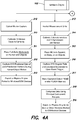
- Figures 4A-B illustrate the process flow performed by the hardware engine 102.
- third party software is utilized to calibrate multiple, e.g. up to 16, near infrared cameras around a centralized volume space, as illustrated by process block 310.
- Retro-reflective markers are then placed on the subject and/or object as seen in Figures 5A-D .
- Data are recorded with devices 212 and transmitted using an Ethernet bus connected to a computer.
- the calibrated XYZ positions of each marker in the capture volume are recorded into a binary encoded file, as illustrated by process block 312.
- the acquired data are exported to the physics engine 102, for example using Windows/OSX devices, for processing, as illustrated by process block 313.
- accelerometers and gyroscopes are calibrated and interfaced with a microcontroller capable of interfacing with any of memory, e.g. RAM or FLASH, and Bluetooth chipsets by internal firmware operations that control the hardware, as illustrated by process block 314.
- Inertial measurement units are placed on points of interest, such as body segments or objects, as illustrated by process block 315.
- a customized event event detection
- data are stored in RAM and/or FLASH memory for later analysis, as illustrated by process block 317.
- Data are simultaneously compressed using principal component analysis, similar as previously described with reference to process block 303, as illustrated by process block 318.
- Data are then exported to a physics engine 100, with, for example, Bluetooth low energy SDK processes on mobile devices (iOS/Android), as illustrated by process block 319.
- a scanning laser is calibrated alongside on-board inertial measurement units that may include accelerometers and gyroscopes, or other positional measurement units, such as Red Green Blue (RGB) video or known environmental conditions, as illustrated by process block 320.
- XYZ point cloud data of human and object motion is then captured, as illustrated by process block 321, and stored to local memory.
- a local skeletal and object tracking algorithm is implemented to track three-dimensional joint and object positions, as illustrated by process block 322.
- the local skeletal and object tracking algorithm may be implemented using known anthropometrics of the human, or known information from the object, alongside edge filtering techniques to identify points of interest on a human or object.
- Skeletal and object data are then also stored in memory, as illustrated by process block 323, and are exported to a physics engine 100 by, for example, Android/iOS devices.
- a physics engine 100 by, for example, Android/iOS devices.
- a local skeleton and object tracking algorithm is then used to extract joint and object positions similar as previously described with reference to process block to 322, as illustrated by process block 326.
- Skeletal and object positional data are then stored to memory, as illustrated by process block 327, and are exported to physics engine 100, by for example, mobile devices (iOS/Android), as illustrated by process block 328.
- markerset 300 comprise a full body markerset 400 and various object markersets, including baseball/softball bat markerset 401, golf clubs markerset 402, tennis racket markerset 403, and other objects that interact with a human body.
- object markersets including baseball/softball bat markerset 401, golf clubs markerset 402, tennis racket markerset 403, and other objects that interact with a human body.
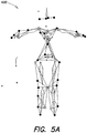
- Figure 5A illustrates conceptually a full body markerset 400 comprises markers attached to bony anatomical landmarks, including, but not limited to: front of the head, back of the head, right side of the head, left side of the head, the T2 vertebrate, the T8 vertebrate, the Xiphoid process of the sternum, the left and right sternoclavicular joints, the Acromioclavicular joint of both shoulders, the middle of the bicep of the upper arms, the lateral and medial epicondyle of both humeruses, middle of the forearms, the medial and lateral styloid processes of both wrists, the tip of the third metacarpal in both hands, the right and left posterior superior iliac spines, the right and left anterior superior iliac spines, the right and left greater trochanters, the middle of both thighs, the medial and lateral epicondyles of the femurs, the right calf, the medial and lateral malleouleses of
- Figure 5B illustrates conceptually a markerset 401 with five markers attached to a hypothetical baseball bat in the following locations: knob of bat, above the handle of the bat, at the center of mass of the bat, at the tip of the bat forming a line between the knob and center of mass, and on the posterior side of the bat at the tip.
- Figure 5C illustrates conceptually a markerset 402 with five markers attached to a hypothetical golf club at the following locations: at the base of the handle, above the handle, at the center of mass, at the base of the club, and at the tip of the clubface to form a direct line of the clubface angle.
- Figure 5D illustrates conceptually a markerset 403 with five markers are placed on a hypothetical tennis racket at the following locations: at the base of the handle, at the intersection of the handle and the racket head, on the left and right sides of the racket head, and at the tip of the racket head.
- wearable technology 102 they comprise in examples any of a plurality of garments 800, which may be made of any material including spandex, Lycra, polyester, in combination with cotton, silk or any other wearable material, to assist with the acquisition of motion data from human subjects and/or accompanying objects.
- garments 800 may be made of any material including spandex, Lycra, polyester, in combination with cotton, silk or any other wearable material, to assist with the acquisition of motion data from human subjects and/or accompanying objects.
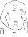
- Each garment 800 comprises multiple data-gathering mechanisms 801, such as MEMS/IMU hardware, which can which can record and transmit motion data wirelessly to an iOS/Android phone or other network enabled device 802.
- Software applications such as those available from Diamond Kinetics, Pittsburgh, PA may be utilized to compute kinematics from MEMS/IMU hardware.
- the mThrow sleeve garment 803, as illustrated in Figure 6A is coupled with motion sensors 801 to monitor workload and performance.
- the mThrow sleeve garment 803 is worn on the throwing arm during practices, games, or rehab sessions. Data may be collected throughout workouts and is transmitted wirelessly to an iOS/Android phone or other network enabled device.
- garment 803 may comprise 801 a six axis accelerometer/gyroscope IMU that interfaces wirelessly via Bluetooth or other protocol with a mobile device 802, such as an iOS/Android smartphone.
- Software applications either executing on the network enabled device or remotely accessible via a network, perform the functions to interact with the physics engine 100 and interactive engine 101.
- Such existing functions include computation of throwing forearm motion, kinetic solutions of elbow reaction forces and torques, algorithmic calculation of throwing workload during game/practice/season/career, pitch and throw counting functions, computation of arm and ball speed, and trends for the use of performance and injury forecasting.
- Principal component analysis of sensor data will also allow for mechanical equivalence models to be created that extract additional segment data that is not directly measured by the sensors.
- the mThrow Pro garment 804 is a comprehensive throwing analysis platform designed to allow athletes of all ages and skill level to receive a full-body biomechanical analysis of their throwing mechanics. Data is gathered with four motion sensors. mThrow Pro garment 804 can be worn during games or practices, and is coupled with interactive applications to provide useful feedback.
- garment 804 may comprise 801 multiple six axis accelerometer/gyroscope IMU's that interfaces wirelessly via Bluetooth or other protocol with a mobile device 802, such as an iOS/Android smartphone.
- Software applications either executing on the network enabled device or remotely accessible via a network, perform the functions to interact with the physics engine 100 and interactive engine 101.
- Such existing functions include computation of throwing forearm, upper arm, pelvis, and upper trunk biomechanical motion, kinetic solution of elbow and shoulder reaction forces and torques, algorithmic calculation of throwing workload during game/practice/season/career, pitch and throw counting functions, computation of ball and arm speed, computation of kinetic chain velocities and accelerations of the pelvis, upper trunk, upper arm, and forearm and their associated temporal reference, and trends for the use of performance and injury forecasting.
- Principal component analysis of sensor data will also allow for mechanical equivalence models to be created that extract additional segment data that is not directly measured by the sensors.
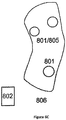
- the mRun ACL Sleeve garment 806, as illustrated in Figure 6C is coupled with motion sensors 801 and EMG muscle activity sensors 805 to detect injury risk factors and workload in athletic movements such as running, sprinting, cutting, and jumping.
- the mRun ACL Sleeve garment 806 can be used on the field of play during games, practice, or training.
- the mRun ACL Sleeve garment 806 may comprise 801 a six axis accelerometer/gyroscope IMU and 805 two EMG sensors on the quadriceps and hamstrings that interfaces wirelessly via Bluetooth or other protocol with a mobile device 802, such as an iOS/Android smartphone.
- Software applications either executing on the network enabled device or remotely accessible via a network, perform the functions to interact with the physics engine 100 and interactive engine 101.
- Such existing functions include computation of lower extremity kinematics, muscle firing activity, and algorithmic computation of movement workload during game/practice/season/career, and trends for the use of performance and injury forecasting.
- Principal component analysis of sensor data will also allow for mechanical equivalence models to be created that extract additional segment data that is not directly measured by the sensors.
- the mRun ACL Leggings Pro garment 807 give athletes in any sport the ability to reduce their risk of injury and enhance performance.
- Garment 807 is a comprehensive movement analysis platform that captures ACL injury risk.
- the mRun ACL Leggings Pro garment 807 uses motion sensors 801 and muscle activity sensors 805 to monitor the entire lower body during any movement.
- mRun ACL Leggings Pro garment 808 may be used during any training platform to allow athletes to undergo an ACL risk screening.
- garment 808 may comprise 801 two six axis accelerometer/gyroscope IMU'sand 805 six EMG sensors on the quadriceps, hamstrings, and gluteus maxims that interfaces wirelessly via Bluetooth or other protocol with a mobile device 802, such as an iOS/Android smartphone.
- Software applications either executing on the network enabled device or remotely accessible via a network, perform the functions to interact with the physics engine 100 and interactive engine 101.
- Such existing functions include computation of full lower extremity kinematics and kinetics, computation of full lower extremity muscle firing activity, algorithmic computation of movement workload during game/practice/season/career, and the use of performance and injury forecasting.
- Principal component analysis of sensor data will also allow for mechanical equivalence models to be created that extract additional segment data that is not directly measured by the sensors.
- the SmartSocks garment 809 can be used in any sport to monitor feet movement, running patterns, and weight distribution. Coupled with force sensor arrays and motion sensors, the SmartSocks garment 810 can interface with any of the garments disclosed herein to provide a more comprehensive experience.
- garment 810 may comprise 801 a six axis accelerometer/gyroscope IMU that interfaces wirelessly via Bluetooth or other protocol with a mobile device 802, such as an iOS/Android smartphone.
- Software applications either executing on the network enabled device or remotely accessible via a network, perform the functions to interact with the physics engine 100 and interactive engine 101.
- Additional sensor technology is to include 810 cardiac sensor for heart rate and respiration rate measurement, 811 blood oxygenation sensor, 812 sweat and hydration sensors, 813 global positioning system sensors for on field movement monitoring, and 814 force sensor arrays for weight distribution and lower extremity kinetic computations. Together, these elements will allow for in depth analysis of player workload during practice and games, while offering performance alerts in the form of dashboards for forecasting performance and injury.
- the example 809 will also have the capability to pair sensor data with 800 804 806 807.
- the mSense device 801 comprises 801 motion sensors, 810 cardiac heart and breathing monitors, 811 oxygen sensors, 812 sweat and hydration sensors, and 813 GPS to monitor team members during gameplay, practice, and training sessions.
- the mSense device 801 is designed for the competitive individual as well as for coaches to monitor their entire team and embeds in on to any garment and interfaces wirelessly with your phone 802 with a user interface in the form of dashboards to monitor player workload.
- device 801 may comprise of a six axis accelerometer/gyroscope IMU that interfaces wirelessly via Bluetooth or other protocol with 802 a mobile device, such as an iOS/Android smartphone.
- Software applications either executing on the network enabled device or remotely accessible via a network, perform the functions to interact with the physics engine 100 and interactive engine 101.
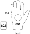
- the mSwing glove garment 816 is coupled with motion sensors 801 to monitor workload and performance of swinging motions such as but not limited to golf swings, baseball batting swings, softball batting swings, tennis swings, and lacrosse swings.
- the mSwing glove garment 816 is worn on the dominant and/or non-dominant arm during practices, games, or rehab sessions. Data may be collected throughout workouts and is transmitted wirelessly to an iOS/Android phone or other network enabled device.
- garment 816 may comprise 801 a six axis accelerometer/gyroscope IMU that interfaces wirelessly via Bluetooth or other protocol with a mobile device 802, such as an iOS/Android smartphone.
- Software applications either executing on the network enabled device or remotely accessible via a network, perform the functions to interact with the physics engine 100 and interactive engine 101.
- Such existing functions include computation of held object motion, kinetic solutions of wrist reaction forces and torques, algorithmic calculation of swinging workload during game/practice/season/career, swing counting functions, computation of held object speed, kinematics and temporal measures, and trends for the use of performance and injury forecasting.
- Principal component analysis of sensor data will also allow for mechanical equivalence models to be created that extract additional segment data that is not directly measured by the sensors.
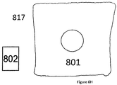
- the mBand wristband garment 817 is coupled with motion sensors 801 to monitor workload and performance of swinging motions such as but not limited to golf swings, baseball batting swings, softball batting swings, tennis swings, and lacrosse swings.
- the mBand wristband garment 817 is worn on the dominant and/or non-dominant arm during practices, games, or rehab sessions. Data may be collected throughout workouts and is transmitted wirelessly to an iOS/Android phone or other network enabled device.
- garment 817 may comprise 801 a six axis accelerometer/gyroscope IMU that interfaces wirelessly via Bluetooth or other protocol with a mobile device 802, such as an iOS/Android smartphone.
- Software applications either executing on the network enabled device or remotely accessible via a network, perform the functions to interact with the physics engine 100 and interactive engine 101.
- Such existing functions include computation of held object motion, kinetic solutions of wrist reaction forces and torques, algorithmic calculation of swinging workload during game/practice/season/career, swing counting functions, computation of held object speed, kinematics and temporal measures, and trends for the use of performance and injury forecasting.
- Principal component analysis of sensor data will also allow for mechanical equivalence models to be created that extract additional segment data that is not directly measured by the sensors.
- a computer system 500 comprises a central processing unit 502 (CPU), a system memory 530, including one or both of a random access memory 532 (RAM) and a read-only memory 534 (ROM), and a system bus 510 that couples the system memory 530 to the CPU 502.
- CPU central processing unit
- RAM random access memory
- ROM read-only memory
- An input/output system containing the basic routines that help to transfer information between elements within the computer architecture 500, such as during startup, can be stored in the ROM 534.
- the computer architecture 500 may further include a mass storage device 520 for storing an operating system 522, software, data, and various program modules 600, associated with an application 580 which may include functionality described herein with reference to any of physics engine 100, hardware engine 102 or interactive engine 100, one or any combination thereof which are executable by a special-purpose application, such as analytics engine 524.
- a mass storage device 520 for storing an operating system 522, software, data, and various program modules 600, associated with an application 580 which may include functionality described herein with reference to any of physics engine 100, hardware engine 102 or interactive engine 100, one or any combination thereof which are executable by a special-purpose application, such as analytics engine 524.
- the mass storage device 520 may be connected to the CPU 502 through a mass storage controller (not illustrated) connected to the bus 510.
- the mass storage device 520 and its associated computer-readable media can provide non-volatile storage for the computer architecture 500.
- computer-readable media can be any available computer storage media that can be accessed by the computer architecture 500.
- computer-readable media may include volatile and non-volatile, removable and non-removable media implemented in any method or technology for the non-transitory storage of information such as computer-readable instructions, data structures, program modules or other data.
- computer-readable media includes, but is not limited to, RAM, ROM, EPROM, EEPROM, flash memory or other solid state memory technology, CD-ROM, digital versatile disks (DVD), HD-DVD, BLU-RAY, or other optical storage, magnetic cassettes, magnetic tape, magnetic disk storage or other magnetic storage devices, or any other medium which can be used to store the desired information and which can be accessed by the computer architecture 500.
- the computer architecture 500 may operate in a networked environment using logical connections to remote physical or virtual entities through a network such as the network 599.
- the computer architecture 500 may connect to the network 599 through a network interface unit 504 connected to the bus 510. It will be appreciated that the network interface unit 504 may also be utilized to connect to other types of networks and remote computer systems.
- the computer architecture 500 may also include an input/output controller for receiving and processing input from a number of other devices, including a keyboard, mouse, or electronic stylus (not illustrated). Similarly, an input/output controller may provide output to a video display 506, a printer, or other type of output device.
- a graphics processor unit 525 may also be connected to the bus 510.
- a number of program modules and data files may be stored in the mass storage device 520 and RAM 532 of the computer architecture 500, including an operating system 522 suitable for controlling the operation of a networked desktop, laptop, server computer, or other computing environment.
- the mass storage device 520, ROM 534, and RAM 532 may also store one or more program modules.
- the mass storage device 520, the ROM 534, and the RAM 532 may store the engine 524 for execution by the CPU 502.
- the engine 524 can include software components for implementing portions of the processes described herein.
- the mass storage device 520, the ROM 534, and the RAM 532 may also store other types of program modules.
- Software modules such as the various modules within the engine 524 may be associated with the system memory 530, the mass storage device 520, or otherwise.
- the analytics engine 524 may be stored on the network 599 and executed by any computer within the network 599.
- Databases 572 and 575 which may be used to store any of the acquired or processed data or idealized models, and/or kinematics and kinetic data described herein, such databases being coupled remotely to network 599 and network interface 504.
- the software modules may include software instructions that, when loaded into the CPU 502 and executed, transform a general-purpose computing system into a special-purpose computing system customized to facilitate all, or part of, the techniques disclosed herein.
- the program modules may provide various tools or techniques by which the computer architecture 500 may participate within the overall systems or operating environments using the components, logic flows, and/or data structures discussed herein.
- the CPU 502 may be constructed from any number of transistors or other circuit elements, which may individually or collectively assume any number of states. More specifically, the CPU 502 may operate as a state machine or finite-state machine. Such a machine may be transformed to a second machine, or specific machine by loading executable instructions contained within the program modules. These computer-executable instructions may transform the CPU 502 by specifying how the CPU 502 transitions between states, thereby transforming the transistors or other circuit elements constituting the CPU 502 from a first machine to a second machine, wherein the second machine may be specifically configured to manage the generation of indices.
- the states of either machine may also be transformed by receiving input from one or more user input devices associated with the input/output controller, the network interface unit 504, other peripherals, other interfaces, or one or more users or other actors.
- Either machine may also transform states, or various physical characteristics of various output devices such as printers, speakers, video displays, or otherwise.
- Encoding of executable computer program code modules may also transform the physical structure of the storage media.
- the specific transformation of physical structure may depend on various factors, in different implementations of this description. Examples of such factors may include, but are not limited to: the technology used to implement the storage media, whether the storage media are characterized as primary or secondary storage, and the like.
- the program modules may transform the physical state of the system memory 530 when the software is encoded therein.
- the software may transform the state of transistors, capacitors, or other discrete circuit elements constituting the system memory 530.
- the storage media may be implemented using magnetic or optical technology.
- the program modules may transform the physical state of magnetic or optical media, when the software is encoded therein. These transformations may include altering the magnetic characteristics of particular locations within given magnetic media. These transformations may also include altering the physical features or characteristics of particular locations within given optical media, to change the optical characteristics of those locations.
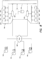
- Figure 8 illustrates conceptually a network topology in which the components of the disclosed system may be implemented.
- Any of the engines 100, 102 or 103 and the data processing systems 110, 113A-C, 112-118, illustrated in the network topology of Figure 8 may be implemented with a processing architecture similar to that illustrated in Figure 7 , including any of a desktop computer, laptop computer, tablet computer or smart phone/personal digital assistant device such as an iPhone or android operating system based device.
- any of the systems illustrated in Figure 8 may be interoperably connected either through a wide area network (WAN) 125 or local area network (LAN) 115 or both, or any hybrid combination thereof using known network infrastructure and components, protocols, and/or topologies.
- WAN wide area network
- LAN local area network
- any of devices 212 - 215 may be connected to hardware engine 102 either through a physical network physically or wirelessly, or any combination thereof.
- any of devices 306 - 309 may be coupled to interface engine 103 either through a physical network or wirelessly, or any combination thereof.
- any of engines 100, 102, 103 may be connected either via WAN 125 or LAN 115, any portion of which may be wireless connection between respective network nodes, the entirety of the system being indicated as system 110.
- Systems 112 - 118 may comprise additional databases more users capable of interacting remotely with system 110.
Landscapes
- Health & Medical Sciences (AREA)
- Engineering & Computer Science (AREA)
- Life Sciences & Earth Sciences (AREA)
- General Health & Medical Sciences (AREA)
- Physics & Mathematics (AREA)
- Biomedical Technology (AREA)
- Public Health (AREA)
- Medical Informatics (AREA)
- Biophysics (AREA)
- Physical Education & Sports Medicine (AREA)
- Business, Economics & Management (AREA)
- Molecular Biology (AREA)
- Pathology (AREA)
- Heart & Thoracic Surgery (AREA)
- Surgery (AREA)
- Animal Behavior & Ethology (AREA)
- Veterinary Medicine (AREA)
- General Physics & Mathematics (AREA)
- Theoretical Computer Science (AREA)
- Primary Health Care (AREA)
- Epidemiology (AREA)
- Computer Vision & Pattern Recognition (AREA)
- Multimedia (AREA)
- Human Computer Interaction (AREA)
- Physiology (AREA)
- Dentistry (AREA)
- Oral & Maxillofacial Surgery (AREA)
- Textile Engineering (AREA)
- Entrepreneurship & Innovation (AREA)
- Educational Administration (AREA)
- Educational Technology (AREA)
- General Business, Economics & Management (AREA)
- Psychiatry (AREA)
- Social Psychology (AREA)
- Radiology & Medical Imaging (AREA)
- Nuclear Medicine, Radiotherapy & Molecular Imaging (AREA)
- Biodiversity & Conservation Biology (AREA)
- Geometry (AREA)
- Spectroscopy & Molecular Physics (AREA)
- Measurement Of The Respiration, Hearing Ability, Form, And Blood Characteristics Of Living Organisms (AREA)
Description
- This disclosure relates to a method and system for delivering biomechanical feedback to human and object motions.
- Systems capable of delivering human and object motion currently exist but are typically very sophisticated and expensive. As well, the format of the feedback provided by these systems varies considerably. Typically, there are no exhaustive methods and systems to deliver biomechanical feedback across multiple platforms and entities consistently. For example, optical motion capture is currently used in motion capture studios and sports technology companies to analyze humans and objects. These motion capture laboratories and studios focus on biomechanical research of human subjects to analyze performance, recovery, and injury risk identifiers, amongst others. Many biomechanical researchers develop proprietary software and processing algorithms to extract kinematic and kinetic measures of human and object motion. The application of physics engines to extract these metrics are based on the precision and location of retro-reflective markers on bony anatomical landmarks of the body and objects. Feedback is usually given in highly technical formats that often leave the test-subject unaware of the true underlying biomechanical flaw and fail to address corrective exercises, drills, and training regimens to improve performance and recovery, and reduce the risk of injury. As well, when and if prescriptive feedback is given, there are few methods to assess compliance with such feedback and there are few systems available for appropriate re-evaluation of the human subject and object.
- Accordingly, a need exists for a system that provides biomechanical feedback in a format which is usable by an actor/athlete to improve their performance and reduce their risk of injury and that is supported by statistical relationship models, interactive platforms, and more advanced hardware platforms.
- Wearable technology is becoming a primary means of assessing human and object motion. This technology is based upon embedding sensor technology in wearable garments. An example of such use is the ability to extract data from one or more on miniaturized accelerometers and gyroscopes for the purpose of reconstructing three-dimensional motion, however, there are limitations to the precision and accuracy of wearable technology that often misleads users with information that is not supported by statistical models. Wearable technology also does not provide comprehensive motion detection of all body and object segments, and, thus, does not allow for extensive prescriptive feedback to improve performance and recovery, and, thereby, reduce the risk of injury. Wearable technology is often wirelessly interfaced with mobile devices to compute kinematics and kinetics, and to display biomechanical feedback in single sessions. That said, there is no cross-platform continuity to keep users engaged, and few methods to monitor compliance and deliver significant feedback.
- Accordingly, a further need exists for a system that incorporates advanced physics engine capabilities, advanced hardware processing and sensor technology, and interactive interfaces to produce meaningful data usable by an actor/athlete to improve their performance and reduce their risk of injury.
- Document
US 2008/0285805 discloses a device for capturing motion and for generating a model representing the closest prio art. - The present invention discloses a device and a method as defined by claims 1 and 8.
- Disclosed is a method and system to deliver biomechanical feedback to subjects. The system utilizes three major elements: (1) multiple hardware data capture devices, including optical motion capture, inertial measurement units, infrared scanning devices, and two-dimensional RGB consecutive image capture devices, (2) a cross-platform compatible physics engine compatible with optical motion capture, inertial measurement units, infrared scanning devices, and two-dimensional RGB consecutive image capture devices, and (3) interactive platforms and user-interfaces to deliver real-time feedback to motions of humans and any objects in their possession and proximity.
- The first element, a cross-platform compatible physics engine, imports data captured from a variety of hardware devices. Data imported from the hardware devices are then fed through kinematics and kinetics algorithms to extract desired biomechanical data. Data is then compiled by the physics engine across multiple subjects and across multiple sessions of a single subject. The physics engine also computes mechanical equivalencies to allow compatibility across hardware platforms. Mechanical equivalencies include correlating database data to injury and performance statistics, correlating discrete kinematics and kinetics of a body to discrete kinematics and kinetics of objects, principal component analysis to correlate time-series data of the body to objects, comparison of subject and object data to compiled databases, and extraction of prescriptive feedback based on all mechanical equivalencies
- The second element, the hardware data capture devices, may comprise a variety of peripheral devices that collect two-dimensional or three-dimensional motion data of subject or object. In one example, such peripheral devices may comprise (1) optical motion capture devices to collect three-dimensional positional data on reflective markers placed on the body and/or an object, (2) inertial measurement units with gyroscopes and accelerometers placed on the body, on an object, or in garments, to collect three-dimensional translation and rotation motion data of object(s) or segment(s) of the subjects body, (3) infrared scanning devices, such as the Microsoft Kinect or Google Tango, to capture three-dimensional point clouds of movement data and incorporate skeletal and object tracking algorithms to extract three-dimensional joint and object positions, and (4) Red Green Blue (RGB) two-dimensional consecutive image capture devices to collect movement images and to incorporate skeletal and object tracking algorithms to extract three-dimensional joint and object positions and kinematics.
- The hardware data capture devices of the second element may further comprise wearable sensor technology which utilizes motion sensing hardware embedded in wearable garments to compute human and object motion. The wearable technology may be coupled the physics engine and interactive interface to offer prescriptive feedback to flaws identified in the subject's and object's motion. Such feedback may be based on an exhaustive body of object motion correlations made during biomechanical research, and be provided to the user via the interactive interface.
- The third element, the interactive interface, utilizes information generated by the physics engine to create a user-interface that displays data to the user. This interactive interface may be implemented in variety of forms such as mobile device screens (iOS/Android), Web-Based interfaces (HTML), Heads-Up-Displays (VR/AR Headsets), and Windows/OSX static formats (spreadsheets, PDF's, etc.). The interactive interface has the capability of feeding information to the user, as well as the ability to collect information from the user for the purpose of monitoring compliance and monitoring usability of the interface. The interactive platform may be utilized to provide to the user insight gathered from biomechanical research and marker-based motion capture methods. Such interactive platforms will be able to offer prescriptive feedback based on motion data gathered from either the wearable technology, or the motion sensing mechanism built into the interactive platform and enable compliance monitoring and continuous engagement across a suite of wearable technology methods. Information may be stored on a back-end storage server and also exported to the physic engine and to one or more of the hardware devices.
- According to one aspect of the disclosure, system for providing prescriptive feedback based on motion of a human subject or object comprises: A) a hardware engine for gathering data about the motion of a subject or object, B) a physics engine operatively coupled to the hardware engine and configured for processing the gathered motion data and correlating the processed motion data with previously stored biomechanical data representing idealized motion models, and C) an interactive interface operatively coupled to the data gathering devices and the physics engine and configured for providing prescriptive feedback on flaws identified in the subject's or object's motion.
- According to another aspect of the disclosure, a method for providing prescriptive feedback based on motion of a human subject or object comprises: A) gathering data about the motion of a subject or object, B) processing the gathered motion data and correlating the processed motion data with previously stored biomechanical data representing idealized motion models, and C) providing prescriptive feedback on flaws identified in the subject's or object's motion. In one embodiment method further comprises D) enabling compliance monitoring of the motion of the subject and/or object.
- According to yet another aspect of the disclosure, a method for offering prescriptive feedback based on motion of a human subject and/or objects comprises: A) gathering motion data from either a wearable garment or device having motion sensing hardware embedded therein or from a motion sensing mechanism built into the interactive platform, B) processing motion data, C) correlating the process motion data with previously stored biomechanical data representing idealized motion models, and D) providing prescriptive feedback on flaws identified in the subject's and object's motion based on the motion data gathered from either the wearable technology or interactive platform.
- The present disclosure is illustratively shown and described with reference to the accompanying drawing in which:
-
Figure 1 illustrates conceptually a system for delivering biomechanical feedback to human and object motion; -
Figure 2 illustrates conceptually a method of the system for delivering biomechanical feedback to human and object motion and the interaction of the physics engine; -
Figure 3 illustrates conceptually a method of the system for delivering biomechanical feedback to human and object motion by use of an interactive engine; -
Figures 4A-B illustrate conceptually a method of the system for delivering biomechanical feedback to human and object motion by use of hardware engines; -
Figure 5 illustrates conceptually a specific marker sets used in the method of biomechanical research and its relation to optical motion capture; -
Figures 6A-H illustrate conceptually examples of wearable technology in accordance with the disclosure; -
Figure 7 illustrates conceptually a diagram of an exemplary computer architecture in accordance with the present disclosure; and -
Figure 8 illustrates conceptually a diagram of an exemplary network topology in which the system may be implemented in accordance with the present disclosure. - The present disclosure will be more completely understood through the following description, which should be read in conjunction with the drawings. In this description, like numbers refer to similar elements within various embodiments of the present disclosure.
- Is used herein, the term "engine" means one or more elements, whether implemented in hardware, software, firmware, or any combination thereof, capable of performing any function described herein, including a collection of such elements which collaboratively perform functions wholly or partially, serially or in parallel, synchronously or asynchronously, remotely or locally, regardless of data formats or protocols.
- Referring to
Figure 1 , a system for providing biomechanical feedback comprises aphysics engine 100, ahardware engine 102, and aninteractive engine 101 to deliver biomechanical feedback on human or object motion. As used herein,hardware engine 102 may comprise one or a plurality of hardware/software devices which function collectively or individually to achieve the described functionality. Similarly, as used herein,interactive engine 101 may comprise one or a plurality of hardware/software devices which function collectively or individually to achieve the described functionality, typically receiving data from or providing data to a subject. -
Physics engine 100 functions as a cross-platform compatible method to transform raw three-dimensional data captured from various hardware data collection devices into usable biomechanical feedback.Figure 2 illustrates conceptually an exemplary process flow of thephysics engine 100. First, thephysics engine 100 is initialized, typically to a startup state with default parameters, as illustrated byprocess block 200. Thephysics engine 100 imports, either in a push or a pull manner over any network infrastructure, wireless or otherwise, either two-dimensional or three-dimensional datasets from thehardware engine 102, as illustrated byprocess block 201. In one embodiment,hardware engine 102 may comprise individually or collectively any of opticalmotion capture device 212,inertial measurement units 213, infrared frompoint scanning devices 214, andimage capture devices 215. Data imported from these devices is provided tophysics engine 100 which performs one or more algorithmic processes to compute kinematics and kinetics of the human body and objects, as illustrated byprocess block 202. - An pseudocode example of the type of kinematic and kinetic algorithmic computations performed by physics engine 11 on data from optical
motion capture device 212,infrared scanning devices 214 and image andvideo capture devices 215, is as follows: - Define a multisegment or single segment biomechanics model comprising bilateral and/or unilateral segments, such as the hands, forearms, upper arms, upper trunk, neck, head, pelvis, upper thighs, lower shanks, feet, and any objects used in the proximity
- Define long-axis unit vectors of the body or object segments in the model using three-dimensional XYZ marker data
- Define Planar-axis unit vectors of each of the above segments
- Compute a cross product of the long and planar axes to determine the third unit vector of each segment
- Compute the cross product of the third unit-vector and the long-axis unit vector to create three orthonormal unit vectors for each segment in the model
- Compute angular velocity vectors of each model segment using a derivative method of unit vectors of each segment
- Compute relative joint angles (in euler and polar coordinate systems) using each segment's set of unit vectors
- Define human mass model using subject weight and height and anthropometrics of body segments to calculate mass moments of inertia about each segment, and center of mass locations
- Compute accelerations of each marker and of each segment center of mass using a five-point central difference filter
- Compute angular accelerations of each model segment using a five point central difference filter of angular velocity
- Compute an inverse dynamics model of motion using angular velocity components of each segment, angular acceleration components of each segment, and linear acceleration components of each segment's center of mass
- Event detection algorithms are used to determine points of interest during a particular motion
- Kinematics and Kinetic values are extracted at points of interest (examples of kinematics and kinetic values are peak angular velocity of the pelvis segment during a sport motion (in meters per second), or shoulder rotation at foot contact during a throwing motion (in degrees)
- Raw sensor data is fused together using an axis-angle integration method.
- ∘ A rotation matrix of the sensor is initialized using the gravity vector during a still point (Gravity can also be detected when there is no still point by measuring integration offset after the axis-angle method is completed)
- ∘ Angular rate data from the gyroscope is integrated into a rotation matrix at each sample during the motion
- ∘ Each rotation matrix from each sample is multiplied consecutively to the initialized rotation matrix in a body-fixed method
- ∘ Acceleration data is transformed into the global frame using the rotation matrix computed from the angular rate data
- ∘ Gravity is subtracted from the rotated acceleration data in the global reference frame
- ∘ Rotated acceleration data is integrated into velocity and position of the sensor and/or any point on a rigid body to which the sensor is attached
- Raw acceleration and angular rate data is transformed into the inertial reference frame at the center of mass of the segment or object to which the sensor is attached
- All processed data is rotated by an offset error that may exist in a system
- All rotated and inertial data is filtered using a fourth order low pass filter
- Inertial reference frame acceleration data and angular rate data are fed into an open-chain inverse dynamics kinetic model to solve for reaction forces and torques about vertices within a human or object mass model defined by anthropometrics, height, weight, or lookup tables of object properties
- Event detection algorithms are used to determine points of interest during a particular motion (An example of an event detection algorithm in baseball pitching encompases the generation of Principal Components of a historical dataset (training data). When a given buffer of data in a hardware device meets the criteria of fitting the principal components, an event (such as a pitch) is detected. Event detection is used to prevent undesired motion from being detected in a given application).
- Kinematics and Kinetic values are extracted at points of interest from integrated positions, velocities, accelerations, angular rates, and reaction force and torque data.
- The above identified process for the computation of kinematics and kinetics data are repeated for multiple trials of a subject's or object's motion and compiled in a memory or database, as illustrated by
process block 203. In one example, similar computed kinematics and kinetics data are compiled across multiple subjects and stored for further analysis, as also illustrated byprocess block 203.Physics engine 100 then provides relevant portions of the compiled kinematics and kinetics data to mechanical equivalency models, as illustrated byprocess block 204. As part of this process,physics engine 100 correlates the compiled data to performance and injury data, as illustrated byprocess block 300. Discrete data are correlated to performance and injury data by way of person correlations and Bayesian mixed regression to eliminate non-contributing factors.Physics engine 100 further correlates discrete kinematics and kinetics data of the body to discrete kinematics and kinetics of the object or other body segments, as illustrated byprocess block 302. Discrete body data are correlated other discrete body and objectdata 302 in a similar method to 300 by way of person correlations and Bayesian mixed regression. Also as part of this process,physics engine 100 correlates time-series data of the body to time-series data of other body parts or objects using principal component analysis, as illustrated byprocess block 303. Time-series segment data are reduced to multiple, e.g. over 80, principal components. The reduced components are then correlated to principal components of other body or object segments and are used to extract additional motion given raw data from one or more body segments. Discrete and time-series data are compared to a database of motion, as illustrated byprocess block 305, by use of averages and standard deviations of data across multiple subjects. Based upon relationships established during process blocks 300, 302, 303, 305,physics engine 100 further extracts prescriptive feedback using correlation models and the subject's/object's motion, as illustrated byprocess block 304. After the prescriptive feedback information is gathered by thephysics engine 100, the prescriptive feedback is exported tointeractive engine 101, as illustrated byprocess block 205, and presented to the subject/object in a matter that facilitates altering the mechanics in a way that leads to increased performance or reduced risk of injury. -
Figure 3 illustrates the process flow performed by theinteractive engine 101. After any initialization of theinteractive engine 101, information is acquired from thephysics engine 100, as illustrated byprocess block 206, either manually, or with automated API's in either a push or pull protocol. Such information is then stored on back end servers and databases, as illustrated byprocess block 207, in a logical manner for reference. Next, the information acquired fromphysics engine 100 is displayed through user interfaces, as illustrated byprocess block 208.Interactive engine 101 may display the information acquired fromphysics engine 100 through any of mobile devices (iOS/Android) 306,spreadsheets 307, web-based interfaces (HTML) 308, and virtual and/or augmented reality heads-updisplays 309, as illustrated byprocess block 208. After such information is displayed, theinteractive engine 101 has the further capability to monitor compliance and usability information through the various interface components ofinteractive engine 101, as illustrated byprocess block 209, by storing compliance information entered by a user or collected by one of the data collection devices comprisinghardware engine 102. Any acquired compliance information may be exported to either thehardware engine 102 and/orphysics engine 100, as applicable, to form a continuous feedback loop, as illustrated byprocess block 210, and as illustrated inFigure 1 .
Figures 4A-B illustrate the process flow performed by thehardware engine 102. For the opticalmotion capture devices 212, third party software is utilized to calibrate multiple, e.g. up to 16, near infrared cameras around a centralized volume space, as illustrated byprocess block 310. Retro-reflective markers are then placed on the subject and/or object as seen inFigures 5A-D . Data are recorded withdevices 212 and transmitted using an Ethernet bus connected to a computer. The calibrated XYZ positions of each marker in the capture volume are recorded into a binary encoded file, as illustrated byprocess block 312. After collection, the acquired data are exported to thephysics engine 102, for example using Windows/OSX devices, for processing, as illustrated byprocess block 313. For theinertial measurement devices 213, accelerometers and gyroscopes are calibrated and interfaced with a microcontroller capable of interfacing with any of memory, e.g. RAM or FLASH, and Bluetooth chipsets by internal firmware operations that control the hardware, as illustrated byprocess block 314. Inertial measurement units are placed on points of interest, such as body segments or objects, as illustrated byprocess block 315. Six axes of data, in addition to time samples, may be recorded continuously. Upon the trigger of a customized event (event detection), as illustrated byprocess block 316, data are stored in RAM and/or FLASH memory for later analysis, as illustrated byprocess block 317. Data are simultaneously compressed using principal component analysis, similar as previously described with reference to process block 303, as illustrated byprocess block 318. Data are then exported to aphysics engine 100, with, for example, Bluetooth low energy SDK processes on mobile devices (iOS/Android), as illustrated byprocess block 319. For theinfrared scanning devices 214, a scanning laser is calibrated alongside on-board inertial measurement units that may include accelerometers and gyroscopes, or other positional measurement units, such as Red Green Blue (RGB) video or known environmental conditions, as illustrated byprocess block 320. XYZ point cloud data of human and object motion is then captured, as illustrated byprocess block 321, and stored to local memory. Simultaneously, a local skeletal and object tracking algorithm is implemented to track three-dimensional joint and object positions, as illustrated byprocess block 322. The local skeletal and object tracking algorithm may be implemented using known anthropometrics of the human, or known information from the object, alongside edge filtering techniques to identify points of interest on a human or object. Skeletal and object data are then also stored in memory, as illustrated byprocess block 323, and are exported to aphysics engine 100 by, for example, Android/iOS devices. For the image andvideo capture devices 215, consecutive two-dimensional RGB images and videos of human object motion are captured, as illustrated by process block 325. A local skeleton and object tracking algorithm is then used to extract joint and object positions similar as previously described with reference to process block to 322, as illustrated byprocess block 326. Skeletal and object positional data are then stored to memory, as illustrated byprocess block 327, and are exported tophysics engine 100, by for example, mobile devices (iOS/Android), as illustrated byprocess block 328. - As seen in
Figure 5A-D ,markerset 300 comprise afull body markerset 400 and various object markersets, including baseball/softball bat markerset 401, golf clubs markerset 402,tennis racket markerset 403, and other objects that interact with a human body.Figure 5A illustrates conceptually afull body markerset 400 comprises markers attached to bony anatomical landmarks, including, but not limited to: front of the head, back of the head, right side of the head, left side of the head, the T2 vertebrate, the T8 vertebrate, the Xiphoid process of the sternum, the left and right sternoclavicular joints, the Acromioclavicular joint of both shoulders, the middle of the bicep of the upper arms, the lateral and medial epicondyle of both humeruses, middle of the forearms, the medial and lateral styloid processes of both wrists, the tip of the third metacarpal in both hands, the right and left posterior superior iliac spines, the right and left anterior superior iliac spines, the right and left greater trochanters, the middle of both thighs, the medial and lateral epicondyles of the femurs, the right calf, the medial and lateral malleouleses of the ankles, the tip of the third metatarsal of both feet, and the tip of the calcaneous in both feet. -
Figure 5B illustrates conceptually amarkerset 401 with five markers attached to a hypothetical baseball bat in the following locations: knob of bat, above the handle of the bat, at the center of mass of the bat, at the tip of the bat forming a line between the knob and center of mass, and on the posterior side of the bat at the tip. -
Figure 5C illustrates conceptually amarkerset 402 with five markers attached to a hypothetical golf club at the following locations: at the base of the handle, above the handle, at the center of mass, at the base of the club, and at the tip of the clubface to form a direct line of the clubface angle. -
Figure 5D illustrates conceptually amarkerset 403 with five markers are placed on a hypothetical tennis racket at the following locations: at the base of the handle, at the intersection of the handle and the racket head, on the left and right sides of the racket head, and at the tip of the racket head. - Referring to
Figures 6A-H ,wearable technology 102, they comprise in examples any of a plurality of garments 800, which may be made of any material including spandex, Lycra, polyester, in combination with cotton, silk or any other wearable material, to assist with the acquisition of motion data from human subjects and/or accompanying objects. Various examples of such garments are described in greater detail below. Each garment 800 comprises multiple data-gathering mechanisms 801, such as MEMS/IMU hardware, which can which can record and transmit motion data wirelessly to an iOS/Android phone or other network enableddevice 802. Software applications, such as those available from Diamond Kinetics, Pittsburgh, PA may be utilized to compute kinematics from MEMS/IMU hardware. - In one example, the
mThrow sleeve garment 803, as illustrated inFigure 6A , is coupled withmotion sensors 801 to monitor workload and performance. ThemThrow sleeve garment 803 is worn on the throwing arm during practices, games, or rehab sessions. Data may be collected throughout workouts and is transmitted wirelessly to an iOS/Android phone or other network enabled device. In such example,garment 803 may comprise 801 a six axis accelerometer/gyroscope IMU that interfaces wirelessly via Bluetooth or other protocol with amobile device 802, such as an iOS/Android smartphone. Software applications, either executing on the network enabled device or remotely accessible via a network, perform the functions to interact with thephysics engine 100 andinteractive engine 101. Such existing functions include computation of throwing forearm motion, kinetic solutions of elbow reaction forces and torques, algorithmic calculation of throwing workload during game/practice/season/career, pitch and throw counting functions, computation of arm and ball speed, and trends for the use of performance and injury forecasting. Principal component analysis of sensor data will also allow for mechanical equivalence models to be created that extract additional segment data that is not directly measured by the sensors. - In another example, the
mThrow Pro garment 804, as illustrated inFigure 6B , is a comprehensive throwing analysis platform designed to allow athletes of all ages and skill level to receive a full-body biomechanical analysis of their throwing mechanics. Data is gathered with four motion sensors.mThrow Pro garment 804 can be worn during games or practices, and is coupled with interactive applications to provide useful feedback. In such example,garment 804 may comprise 801 multiple six axis accelerometer/gyroscope IMU's that interfaces wirelessly via Bluetooth or other protocol with amobile device 802, such as an iOS/Android smartphone. Software applications, either executing on the network enabled device or remotely accessible via a network, perform the functions to interact with thephysics engine 100 andinteractive engine 101. Such existing functions include computation of throwing forearm, upper arm, pelvis, and upper trunk biomechanical motion, kinetic solution of elbow and shoulder reaction forces and torques, algorithmic calculation of throwing workload during game/practice/season/career, pitch and throw counting functions, computation of ball and arm speed, computation of kinetic chain velocities and accelerations of the pelvis, upper trunk, upper arm, and forearm and their associated temporal reference, and trends for the use of performance and injury forecasting. Principal component analysis of sensor data will also allow for mechanical equivalence models to be created that extract additional segment data that is not directly measured by the sensors. - In another example, the mRun
ACL Sleeve garment 806, as illustrated inFigure 6C , is coupled withmotion sensors 801 and EMG muscle activity sensors 805 to detect injury risk factors and workload in athletic movements such as running, sprinting, cutting, and jumping. The mRunACL Sleeve garment 806 can be used on the field of play during games, practice, or training. The mRunACL Sleeve garment 806 may comprise 801 a six axis accelerometer/gyroscope IMU and 805 two EMG sensors on the quadriceps and hamstrings that interfaces wirelessly via Bluetooth or other protocol with amobile device 802, such as an iOS/Android smartphone. Software applications, either executing on the network enabled device or remotely accessible via a network, perform the functions to interact with thephysics engine 100 andinteractive engine 101. Such existing functions include computation of lower extremity kinematics, muscle firing activity, and algorithmic computation of movement workload during game/practice/season/career, and trends for the use of performance and injury forecasting. Principal component analysis of sensor data will also allow for mechanical equivalence models to be created that extract additional segment data that is not directly measured by the sensors. - In another example, the mRun ACL Leggings Pro
garment 807, as illustrated inFigure 6D , give athletes in any sport the ability to reduce their risk of injury and enhance performance.Garment 807 is a comprehensive movement analysis platform that captures ACL injury risk. The mRun ACL Leggings Progarment 807 usesmotion sensors 801 and muscle activity sensors 805 to monitor the entire lower body during any movement. mRun ACL Leggings Pro garment 808 may be used during any training platform to allow athletes to undergo an ACL risk screening. In such example, garment 808 may comprise 801 two six axis accelerometer/gyroscope IMU'sand 805 six EMG sensors on the quadriceps, hamstrings, and gluteus medius that interfaces wirelessly via Bluetooth or other protocol with amobile device 802, such as an iOS/Android smartphone. Software applications, either executing on the network enabled device or remotely accessible via a network, perform the functions to interact with thephysics engine 100 andinteractive engine 101. Such existing functions include computation of full lower extremity kinematics and kinetics, computation of full lower extremity muscle firing activity, algorithmic computation of movement workload during game/practice/season/career, and the use of performance and injury forecasting. Principal component analysis of sensor data will also allow for mechanical equivalence models to be created that extract additional segment data that is not directly measured by the sensors. - In another example, the
SmartSocks garment 809, as illustrated inFigure 6E , can be used in any sport to monitor feet movement, running patterns, and weight distribution. Coupled with force sensor arrays and motion sensors, theSmartSocks garment 810 can interface with any of the garments disclosed herein to provide a more comprehensive experience. In such example,garment 810 may comprise 801 a six axis accelerometer/gyroscope IMU that interfaces wirelessly via Bluetooth or other protocol with amobile device 802, such as an iOS/Android smartphone. Software applications, either executing on the network enabled device or remotely accessible via a network, perform the functions to interact with thephysics engine 100 andinteractive engine 101. Additional sensor technology is to include 810 cardiac sensor for heart rate and respiration rate measurement, 811 blood oxygenation sensor, 812 sweat and hydration sensors, 813 global positioning system sensors for on field movement monitoring, and 814 force sensor arrays for weight distribution and lower extremity kinetic computations. Together, these elements will allow for in depth analysis of player workload during practice and games, while offering performance alerts in the form of dashboards for forecasting performance and injury. The example 809 will also have the capability to pair sensor data with 800 804 806 807. - In another example, the
mSense device 801, as illustrated inFigure 6F , comprises 801 motion sensors, 810 cardiac heart and breathing monitors, 811 oxygen sensors, 812 sweat and hydration sensors, and 813 GPS to monitor team members during gameplay, practice, and training sessions. ThemSense device 801 is designed for the competitive individual as well as for coaches to monitor their entire team and embeds in on to any garment and interfaces wirelessly with yourphone 802 with a user interface in the form of dashboards to monitor player workload. In such example,device 801 may comprise of a six axis accelerometer/gyroscope IMU that interfaces wirelessly via Bluetooth or other protocol with 802 a mobile device, such as an iOS/Android smartphone. Software applications, either executing on the network enabled device or remotely accessible via a network, perform the functions to interact with thephysics engine 100 andinteractive engine 101. - In another example, the
mSwing glove garment 816, as illustrated inFigure 6G , is coupled withmotion sensors 801 to monitor workload and performance of swinging motions such as but not limited to golf swings, baseball batting swings, softball batting swings, tennis swings, and lacrosse swings. ThemSwing glove garment 816 is worn on the dominant and/or non-dominant arm during practices, games, or rehab sessions. Data may be collected throughout workouts and is transmitted wirelessly to an iOS/Android phone or other network enabled device. In such example,garment 816 may comprise 801 a six axis accelerometer/gyroscope IMU that interfaces wirelessly via Bluetooth or other protocol with amobile device 802, such as an iOS/Android smartphone. Software applications, either executing on the network enabled device or remotely accessible via a network, perform the functions to interact with thephysics engine 100 andinteractive engine 101. Such existing functions include computation of held object motion, kinetic solutions of wrist reaction forces and torques, algorithmic calculation of swinging workload during game/practice/season/career, swing counting functions, computation of held object speed, kinematics and temporal measures, and trends for the use of performance and injury forecasting. Principal component analysis of sensor data will also allow for mechanical equivalence models to be created that extract additional segment data that is not directly measured by the sensors. - In another example, the
mBand wristband garment 817, as illustrated inFigure 6H , is coupled withmotion sensors 801 to monitor workload and performance of swinging motions such as but not limited to golf swings, baseball batting swings, softball batting swings, tennis swings, and lacrosse swings. ThemBand wristband garment 817 is worn on the dominant and/or non-dominant arm during practices, games, or rehab sessions. Data may be collected throughout workouts and is transmitted wirelessly to an iOS/Android phone or other network enabled device. In such example,garment 817 may comprise 801 a six axis accelerometer/gyroscope IMU that interfaces wirelessly via Bluetooth or other protocol with amobile device 802, such as an iOS/Android smartphone. Software applications, either executing on the network enabled device or remotely accessible via a network, perform the functions to interact with thephysics engine 100 andinteractive engine 101. Such existing functions include computation of held object motion, kinetic solutions of wrist reaction forces and torques, algorithmic calculation of swinging workload during game/practice/season/career, swing counting functions, computation of held object speed, kinematics and temporal measures, and trends for the use of performance and injury forecasting. Principal component analysis of sensor data will also allow for mechanical equivalence models to be created that extract additional segment data that is not directly measured by the sensors. - The previously described
physics engine 100 and the processes or functions performed thereby may be implemented with computer program code executing under the control of an operating system and running on one or more primary hardware platforms as described with reference toFigure 7 . Referring toFigure 7 , acomputer system 500 comprises a central processing unit 502 (CPU), asystem memory 530, including one or both of a random access memory 532 (RAM) and a read-only memory 534 (ROM), and asystem bus 510 that couples thesystem memory 530 to theCPU 502. An input/output system containing the basic routines that help to transfer information between elements within thecomputer architecture 500, such as during startup, can be stored in theROM 534. Thecomputer architecture 500 may further include amass storage device 520 for storing anoperating system 522, software, data, and various program modules 600, associated with anapplication 580 which may include functionality described herein with reference to any ofphysics engine 100,hardware engine 102 orinteractive engine 100, one or any combination thereof which are executable by a special-purpose application, such asanalytics engine 524. - The
mass storage device 520 may be connected to theCPU 502 through a mass storage controller (not illustrated) connected to thebus 510. Themass storage device 520 and its associated computer-readable media can provide non-volatile storage for thecomputer architecture 500. Although the description of computer-readable media contained herein refers to a mass storage device, such as a hard disk or CD-ROM drive, it should be appreciated by those skilled in the art that computer-readable media can be any available computer storage media that can be accessed by thecomputer architecture 500. - By way of example, and not limitation, computer-readable media may include volatile and non-volatile, removable and non-removable media implemented in any method or technology for the non-transitory storage of information such as computer-readable instructions, data structures, program modules or other data. For example, computer-readable media includes, but is not limited to, RAM, ROM, EPROM, EEPROM, flash memory or other solid state memory technology, CD-ROM, digital versatile disks (DVD), HD-DVD, BLU-RAY, or other optical storage, magnetic cassettes, magnetic tape, magnetic disk storage or other magnetic storage devices, or any other medium which can be used to store the desired information and which can be accessed by the
computer architecture 500. - According to various examples, the
computer architecture 500 may operate in a networked environment using logical connections to remote physical or virtual entities through a network such as thenetwork 599. Thecomputer architecture 500 may connect to thenetwork 599 through anetwork interface unit 504 connected to thebus 510. It will be appreciated that thenetwork interface unit 504 may also be utilized to connect to other types of networks and remote computer systems. Thecomputer architecture 500 may also include an input/output controller for receiving and processing input from a number of other devices, including a keyboard, mouse, or electronic stylus (not illustrated). Similarly, an input/output controller may provide output to avideo display 506, a printer, or other type of output device. Agraphics processor unit 525 may also be connected to thebus 510. - As mentioned briefly above, a number of program modules and data files may be stored in the
mass storage device 520 andRAM 532 of thecomputer architecture 500, including anoperating system 522 suitable for controlling the operation of a networked desktop, laptop, server computer, or other computing environment. Themass storage device 520,ROM 534, andRAM 532 may also store one or more program modules. In particular, themass storage device 520, theROM 534, and theRAM 532 may store theengine 524 for execution by theCPU 502. Theengine 524 can include software components for implementing portions of the processes described herein. Themass storage device 520, theROM 534, and theRAM 532 may also store other types of program modules. - Software modules, such as the various modules within the
engine 524 may be associated with thesystem memory 530, themass storage device 520, or otherwise. According to examples, theanalytics engine 524 may be stored on thenetwork 599 and executed by any computer within thenetwork 599.Databases network interface 504. - The software modules may include software instructions that, when loaded into the
CPU 502 and executed, transform a general-purpose computing system into a special-purpose computing system customized to facilitate all, or part of, the techniques disclosed herein. As detailed throughout this description, the program modules may provide various tools or techniques by which thecomputer architecture 500 may participate within the overall systems or operating environments using the components, logic flows, and/or data structures discussed herein. - The
CPU 502 may be constructed from any number of transistors or other circuit elements, which may individually or collectively assume any number of states. More specifically, theCPU 502 may operate as a state machine or finite-state machine. Such a machine may be transformed to a second machine, or specific machine by loading executable instructions contained within the program modules. These computer-executable instructions may transform theCPU 502 by specifying how theCPU 502 transitions between states, thereby transforming the transistors or other circuit elements constituting theCPU 502 from a first machine to a second machine, wherein the second machine may be specifically configured to manage the generation of indices. The states of either machine may also be transformed by receiving input from one or more user input devices associated with the input/output controller, thenetwork interface unit 504, other peripherals, other interfaces, or one or more users or other actors. Either machine may also transform states, or various physical characteristics of various output devices such as printers, speakers, video displays, or otherwise. - Encoding of executable computer program code modules may also transform the physical structure of the storage media. The specific transformation of physical structure may depend on various factors, in different implementations of this description. Examples of such factors may include, but are not limited to: the technology used to implement the storage media, whether the storage media are characterized as primary or secondary storage, and the like. For example, if the storage media are implemented as semiconductor-based memory, the program modules may transform the physical state of the
system memory 530 when the software is encoded therein. For example, the software may transform the state of transistors, capacitors, or other discrete circuit elements constituting thesystem memory 530. - As another example, the storage media may be implemented using magnetic or optical technology. In such implementations, the program modules may transform the physical state of magnetic or optical media, when the software is encoded therein. These transformations may include altering the magnetic characteristics of particular locations within given magnetic media. These transformations may also include altering the physical features or characteristics of particular locations within given optical media, to change the optical characteristics of those locations.
-
Figure 8 illustrates conceptually a network topology in which the components of the disclosed system may be implemented. Any of theengines data processing systems 110, 113A-C, 112-118, illustrated in the network topology ofFigure 8 may be implemented with a processing architecture similar to that illustrated inFigure 7 , including any of a desktop computer, laptop computer, tablet computer or smart phone/personal digital assistant device such as an iPhone or android operating system based device. Note that any of the systems illustrated inFigure 8 may be interoperably connected either through a wide area network (WAN) 125 or local area network (LAN) 115 or both, or any hybrid combination thereof using known network infrastructure and components, protocols, and/or topologies. For example, any of devices 212 - 215 may be connected tohardware engine 102 either through a physical network physically or wirelessly, or any combination thereof. Similarly any of devices 306 - 309 may be coupled tointerface engine 103 either through a physical network or wirelessly, or any combination thereof. Similarly any ofengines WAN 125 orLAN 115, any portion of which may be wireless connection between respective network nodes, the entirety of the system being indicated assystem 110. Systems 112 - 118 may comprise additional databases more users capable of interacting remotely withsystem 110. - The reader can appreciate that the various systems and elements and methods described herein enables delivery of near real-time feedback to motions of human subjects and any objects in their possession and proximity.
- The various embodiments of the system and techniques disclosed herein have been described with reference to specific sports and/or garments related to such activities. Any type of wearable garment which is capable of transmitting motion data useful for analysis may be utilized with the systems and techniques described herein. Further, notwithstanding the network implementation described, any existing or future network or communications infrastructure technologies may be utilized, including any combination of public and private networks. In addition, although specific algorithmic flow diagrams or data structures may have been illustrated, these are for exemplary purposes only, other processes which achieve the same functions or utilized different data structures or formats are contemplated to be within the scope of the concepts described herein.
Claims (14)
- A system for providing prescriptive feedback based on motion of a human subject or object comprising:A) a hardware engine comprising a plurality of data gathering devices for collectively gathering data about the motion of a subject or object,B) a physics engine operatively coupled to the hardware engine and configured for processing the gathered motion data and correlating the processed motion data with previously stored biomechanical data representing idealized motion models and identifying flaws in the subject's or object's motion, andC) an interactive interface operatively coupled to the data gathering devices and the physics engine and configured for providing prescriptive feedback on flaws identified in the subject's or object's motion in the form of meaningful data usable by the subject to improve performance or reduce risk of injury.
- The system of claim 1 wherein the interactive interface is further configured for providing information to a subject and collecting information from the subject for the purpose of enabling compliance monitoring of the subject's or object's motion.
- The system of any preceding claim wherein the hardware engine comprises at least one data gathering device configured for gathering data about the motion of a subject or object, the data gathering device comprising any of an optical motion capture device to collect three-dimensional positional data from reflective markers placed on the subject or object, an inertial measurement unit disposed on the subject or object to collect three-dimensional translation and rotation motion data or an infrared scanning device configured to capture three-dimensional point clouds of movement data.
- The system of any preceding claim wherein the physics engine is configured to perform one or more algorithmic processes of the gathered motion data to compute kinematics and kinetics of the subject or object.
- The system of any preceding claim wherein the physics engine is configured to determine points of interest on a subject or object during a particular motion using event detection algorithms.
- The system of any preceding claim wherein the physics engine is configured to define a model of the subject having a plurality of segments.
- The system of claim 6 wherein the physics engine is further configured to compute an inverse dynamics model of motion of the subject using angular velocity components of each segment, angular acceleration components of each segment, and linear acceleration components of each segment center of mass.
- A method for providing prescriptive feedback based on motion of a human subject or object comprising:A) gathering data about the motion of a subject or object,B) processing the gathered motion data and correlating the processed motion data with previously stored biomechanical data representing idealized motion models and identifying flaws in the subject's and object's motion, andC) providing prescriptive feedback on flaws identified in the subject's or object's motion in the form of meaningful data usable by the subject to improve performance or reduce risk of injury.
- The method of claim 8 further comprising:
E) providing information to a subject and collecting information from the subject for the purpose of enabling compliance monitoring of motion of the subject or object with an interactive interface. - The method of claim 8 wherein A) gathering data about the motion of a subject or object comprises any of: gathering data with an optical motion capture device to collect three-dimensional positional data from reflective markers placed on the subject or object, gathering data with an inertial measurement unit disposed on the subject or object to collect three-dimensional translation and rotation motion data, or gathering data with an infrared scanning device configured to capture three-dimensional point clouds of movement data.
- The method of claim 8 wherein B) comprises:
B1) performing one or more algorithmic processes of the gathered motion data to compute kinematics and kinetics of the subject or object. - The method of any one of claims 8 to 11 wherein B) comprises:
B1) determining points of interest on a subject or object during a particular motion using event detection algorithms. - The method of any one of claims 8 to 11 wherein B) comprises:
B1) defining a model of the subject having a plurality of segments. - The method of claim 13 wherein B) further comprises:
B2) computing an inverse dynamics model of motion of the subject using angular velocity components of each segment, angular acceleration components of each segment, and linear acceleration components of each segment center of mass.
Applications Claiming Priority (2)
| Application Number | Priority Date | Filing Date | Title |
|---|---|---|---|
| US201461954375P | 2014-03-17 | 2014-03-17 | |
| PCT/US2015/021004 WO2015142877A1 (en) | 2014-03-17 | 2015-03-17 | Method and system for delivering biomechanical feedback to human and object motion |
Publications (3)
| Publication Number | Publication Date |
|---|---|
| EP3120256A1 EP3120256A1 (en) | 2017-01-25 |
| EP3120256A4 EP3120256A4 (en) | 2018-01-03 |
| EP3120256B1 true EP3120256B1 (en) | 2020-02-12 |
Family
ID=54067612
Family Applications (1)
| Application Number | Title | Priority Date | Filing Date |
|---|---|---|---|
| EP15764196.0A Active EP3120256B1 (en) | 2014-03-17 | 2015-03-17 | Method and system for delivering biomechanical feedback to human and object motion |
Country Status (5)
| Country | Link |
|---|---|
| US (2) | US20150257682A1 (en) |
| EP (1) | EP3120256B1 (en) |
| JP (1) | JP2017520336A (en) |
| CA (1) | CA2943113C (en) |
| WO (1) | WO2015142877A1 (en) |
Families Citing this family (42)
| Publication number | Priority date | Publication date | Assignee | Title |
|---|---|---|---|---|
| US10004455B2 (en) * | 2014-04-03 | 2018-06-26 | Universiti Brunei Darussalam | Realtime biofeedback mechanism and data presentation for knee injury rehabilitation monitoring and a soft real time intelligent system thereof |
| US9900722B2 (en) | 2014-04-29 | 2018-02-20 | Microsoft Technology Licensing, Llc | HRTF personalization based on anthropometric features |
| WO2017011753A1 (en) * | 2015-07-15 | 2017-01-19 | Massachusetts Institute Of Technology | System and method for providing reconstruction of human surfaces from orientation data |
| JP2017045160A (en) * | 2015-08-25 | 2017-03-02 | ルネサスエレクトロニクス株式会社 | Skill guidance verification system and skill guidance verification program |
| WO2017055792A1 (en) * | 2015-10-02 | 2017-04-06 | Mas Innovation (Pvt) Limited | System and method for monitoring the running technique of a user |
| WO2017062544A1 (en) * | 2015-10-06 | 2017-04-13 | University Of Pittsburgh-Of The Commonwealth System Of Higher Education | Method, device and system for sensing neuromuscular, physiological, biomechanical, and musculoskeletal activity |
| WO2017120367A1 (en) * | 2016-01-05 | 2017-07-13 | Wearable Experiments Inc. | Systems and methods for smart athletic wear |
| AU2017212156A1 (en) * | 2016-01-25 | 2018-09-06 | B-Temia Inc. | 3D geolocation system |
| US10665019B2 (en) * | 2016-03-24 | 2020-05-26 | Qualcomm Incorporated | Spatial relationships for integration of visual images of physical environment into virtual reality |
| US11006856B2 (en) * | 2016-05-17 | 2021-05-18 | Harshavardhana Narayana Kikkeri | Method and program product for multi-joint tracking combining embedded sensors and an external sensor |
| US10249090B2 (en) | 2016-06-09 | 2019-04-02 | Microsoft Technology Licensing, Llc | Robust optical disambiguation and tracking of two or more hand-held controllers with passive optical and inertial tracking |
| WO2018022602A1 (en) * | 2016-07-25 | 2018-02-01 | Ctrl-Labs Corporation | Methods and apparatus for predicting musculo-skeletal position information using wearable autonomous sensors |
| US9858388B1 (en) | 2016-09-26 | 2018-01-02 | International Business Machines Corporation | Health monitoring using parallel cognitive processing |
| KR101975056B1 (en) * | 2016-12-02 | 2019-05-07 | 한국전자통신연구원 | User customized training system and method for providing training service there of |
| US10278002B2 (en) * | 2017-03-20 | 2019-04-30 | Microsoft Technology Licensing, Llc | Systems and methods for non-parametric processing of head geometry for HRTF personalization |
| US20200129811A1 (en) * | 2017-03-29 | 2020-04-30 | Benjamin Douglas Kruger | Method of Coaching an Athlete Using Wearable Body Monitors |
| US20200188732A1 (en) * | 2017-03-29 | 2020-06-18 | Benjamin Douglas Kruger | Wearable Body Monitors and System for Analyzing Data and Predicting the Trajectory of an Object |
| WO2018200897A1 (en) | 2017-04-27 | 2018-11-01 | TrinityVR, Inc. | Baseball pitch simulation and swing analysis using virtual reality device and system |
| EP3639269B1 (en) * | 2017-06-16 | 2025-08-06 | Medstar Health | Systems for injury prevention and rehabilitation |
| KR102193629B1 (en) | 2018-01-23 | 2020-12-21 | 구글 엘엘씨 | Selective adaptation and utilization of noise reduction technology in call phrase detection |
| TWI681798B (en) * | 2018-02-12 | 2020-01-11 | 莊龍飛 | Scoring method and system for exercise course and computer program product |
| US10719712B2 (en) * | 2018-02-26 | 2020-07-21 | Canon Kabushiki Kaisha | Classify actions in video segments using play state information |
| US11660526B2 (en) | 2018-03-01 | 2023-05-30 | Sony Interactive Entertainment Inc. | Estimation apparatus, estimation method, and program |
| CN208641671U (en) * | 2018-05-29 | 2019-03-26 | 京东方科技集团股份有限公司 | Body-building cushion |
| US11205443B2 (en) | 2018-07-27 | 2021-12-21 | Microsoft Technology Licensing, Llc | Systems, methods, and computer-readable media for improved audio feature discovery using a neural network |
| US11510035B2 (en) * | 2018-11-07 | 2022-11-22 | Kyle Craig | Wearable device for measuring body kinetics |
| US12514499B2 (en) * | 2018-11-07 | 2026-01-06 | Caevisus, Inc. | Wearable device for measuring body kinetics |
| JP7293793B2 (en) * | 2019-03-27 | 2023-06-20 | セイコーエプソン株式会社 | Swing analysis method and swing analysis device |
| CN110176162B (en) * | 2019-06-25 | 2021-09-21 | 范平 | Wearable system and teaching method applied to wearable system |
| CN110264798B (en) * | 2019-06-25 | 2021-09-07 | 范平 | Wearable system and teaching method applied to wearable system |
| US11645873B1 (en) | 2020-03-20 | 2023-05-09 | 18Birdies Llc | Systems, media, and methods providing a golf swing coach |
| CN111569397B (en) * | 2020-04-30 | 2021-06-15 | 东莞全创光电实业有限公司 | Handle motion counting method and terminal |
| US11556004B2 (en) * | 2020-12-11 | 2023-01-17 | Samsung Electronics Co., Ltd. | Method and apparatus for estimating position of image display device |
| WO2022144929A1 (en) * | 2021-01-03 | 2022-07-07 | Tweek Labs Private Limited | Modular body-motion analysis system, device and method thereof |
| US12367600B2 (en) * | 2021-05-11 | 2025-07-22 | Tam Technologies, Inc. | Methods and systems for representing a user |
| JP7716260B2 (en) * | 2021-07-29 | 2025-07-31 | 美津濃株式会社 | Analysis system and analysis method |
| EP4183336B1 (en) * | 2021-11-13 | 2024-02-07 | Tata Consultancy Services Limited | Method and a system for real time analysis of range of motion (rom) |
| US12393263B2 (en) | 2021-12-08 | 2025-08-19 | Riley J. Brooksher | Systems and methods related to monitoring, communicating, and/or analyzing bodily movements |
| US12377337B1 (en) * | 2022-01-24 | 2025-08-05 | Be ONE Sports, LLC | Athletic performance analysis and training system and method |
| CN114469078B (en) * | 2022-01-28 | 2023-06-23 | 北京航空航天大学 | A human motion detection method based on optical inertial fusion |
| TWI797048B (en) * | 2022-09-01 | 2023-03-21 | 洞見資訊股份有限公司 | Skeleton correction equipment design system and skeleton correction equipment thereof |
| US12223662B1 (en) * | 2022-10-26 | 2025-02-11 | United States Of America As Represented By The Secretary Of The Air Force | Method of kinematically analyzing ejecta from a dynamic event |
Family Cites Families (18)
| Publication number | Priority date | Publication date | Assignee | Title |
|---|---|---|---|---|
| JPH07313648A (en) * | 1990-12-25 | 1995-12-05 | Kongouzen Souhonzan Shiyourinji | Motor movement development method |
| JP2926040B2 (en) * | 1997-05-09 | 1999-07-28 | ダイセル化学工業株式会社 | Gas generator and airbag device for airbag |
| US20050105772A1 (en) * | 1998-08-10 | 2005-05-19 | Nestor Voronka | Optical body tracker |
| EP1322224B1 (en) * | 2000-09-14 | 2008-11-05 | The Board Of Trustees Of The Leland Stanford Junior University | Assessing condition of a joint and cartilage loss |
| US7684896B2 (en) * | 2001-06-29 | 2010-03-23 | Honda Motor Co., Ltd. | System and method of estimating joint loads using an approach of closed form dynamics |
| US20050010577A1 (en) * | 2003-07-11 | 2005-01-13 | Microsoft Corporation | Method and apparatus for generating Web content |
| JP4291093B2 (en) * | 2003-09-11 | 2009-07-08 | 本田技研工業株式会社 | Method for estimating joint moments of biped walking objects |
| US7981059B2 (en) * | 2005-02-28 | 2011-07-19 | National University Corporation NARA Institute of Science and Technology | Driving force calculating device, driving force calculating method, power assisting device, program, and computer-readable storage medium |
| JP2007121217A (en) * | 2005-10-31 | 2007-05-17 | Advanced Telecommunication Research Institute International | Body motion analysis device |
| US20100201512A1 (en) * | 2006-01-09 | 2010-08-12 | Harold Dan Stirling | Apparatus, systems, and methods for evaluating body movements |
| EP1970005B1 (en) * | 2007-03-15 | 2012-10-03 | Xsens Holding B.V. | A system and a method for motion tracking using a calibration unit |
| JP5641222B2 (en) * | 2010-12-06 | 2014-12-17 | セイコーエプソン株式会社 | Arithmetic processing device, motion analysis device, display method and program |
| US20120259650A1 (en) * | 2011-04-07 | 2012-10-11 | Full Recovery, Inc. | Systems and methods for remote monitoring, management and optimization of physical therapy treatment |
| US8576929B2 (en) * | 2011-06-30 | 2013-11-05 | Broadcom Corporation | Powerline communication device |
| JP2013059016A (en) * | 2011-08-12 | 2013-03-28 | Sony Corp | Image processing device, method, and program |
| US8944940B2 (en) * | 2011-08-29 | 2015-02-03 | Icuemotion, Llc | Racket sport inertial sensor motion tracking analysis |
| US20130244211A1 (en) * | 2012-03-15 | 2013-09-19 | The Board Of Trustees Of The Leland Stanford Junior University | Systems and methods for measuring, analyzing, and providing feedback for movement in multidimensional space |
| US20140002266A1 (en) * | 2012-07-02 | 2014-01-02 | David Hayner | Methods and Apparatus for Muscle Memory Training |
-
2015
- 2015-03-17 WO PCT/US2015/021004 patent/WO2015142877A1/en not_active Ceased
- 2015-03-17 CA CA2943113A patent/CA2943113C/en active Active
- 2015-03-17 US US14/660,338 patent/US20150257682A1/en not_active Abandoned
- 2015-03-17 EP EP15764196.0A patent/EP3120256B1/en active Active
- 2015-03-17 JP JP2017501083A patent/JP2017520336A/en active Pending
-
2017
- 2017-10-26 US US15/794,579 patent/US10314536B2/en active Active
Non-Patent Citations (1)
| Title |
|---|
| None * |
Also Published As
| Publication number | Publication date |
|---|---|
| WO2015142877A1 (en) | 2015-09-24 |
| EP3120256A4 (en) | 2018-01-03 |
| CA2943113A1 (en) | 2015-09-24 |
| EP3120256A1 (en) | 2017-01-25 |
| CA2943113C (en) | 2022-10-25 |
| US10314536B2 (en) | 2019-06-11 |
| US20180177450A1 (en) | 2018-06-28 |
| US20150257682A1 (en) | 2015-09-17 |
| JP2017520336A (en) | 2017-07-27 |
Similar Documents
| Publication | Publication Date | Title |
|---|---|---|
| US10314536B2 (en) | Method and system for delivering biomechanical feedback to human and object motion | |
| US11238636B2 (en) | Method and apparatus for sport-specific training with captured body motions | |
| US11037369B2 (en) | Virtual or augmented reality rehabilitation | |
| JP6938542B2 (en) | Methods and program products for articulated tracking that combine embedded and external sensors | |
| US11321894B2 (en) | Motion control via an article of clothing | |
| US11266328B2 (en) | Systems and methods for evaluating body motion | |
| US11210834B1 (en) | Article of clothing facilitating capture of motions | |
| US10004949B2 (en) | Monitoring performance and generating feedback with athletic-performance models | |
| CN107330967B (en) | Rider motion posture capturing and three-dimensional reconstruction system based on inertial sensing technology | |
| US11775050B2 (en) | Motion pattern recognition using wearable motion sensors | |
| US11798216B2 (en) | Motion detection method and system | |
| Brown et al. | The X-Factor: An evaluation of common methods used to analyse major inter-segment kinematics during the golf swing | |
| Wei et al. | Real-time 3D arm motion tracking using the 6-axis IMU sensor of a smartwatch | |
| US20170193140A1 (en) | Monitoring Performance and Generating Feedback with Sensor Environment | |
| Ruffaldi et al. | Sensor fusion for complex articulated body tracking applied in rowing | |
| Nie et al. | [Retracted] The Construction of Basketball Training System Based on Motion Capture Technology | |
| Rahman et al. | Modeling therapy rehabilitation sessions using non-invasive serious games | |
| Gharasuie et al. | Performance monitoring for exercise movements using mobile cameras | |
| WO2023127870A1 (en) | Care support device, care support program, and care support method | |
| Collins et al. | Stroke patient daily activity observation system | |
| Rahman | Web-based multimedia hand-therapy framework for measuring forward and inverse kinematic data | |
| Bhadane et al. | A Systematic Review of Movement Tracking for Real‐Time Monitoring of Physical Exercises in the Gym | |
| Bucciero et al. | A biomechanical analysis system of posture | |
| Wang et al. | Research on multiperson motion capture system combining target positioning and inertial attitude sensing technology | |
| Chen et al. | Multimodal pose estimation and simulation modelling for real-time human motion analysis |
Legal Events
| Date | Code | Title | Description |
|---|---|---|---|
| STAA | Information on the status of an ep patent application or granted ep patent |
Free format text: STATUS: THE INTERNATIONAL PUBLICATION HAS BEEN MADE |
|
| PUAI | Public reference made under article 153(3) epc to a published international application that has entered the european phase |
Free format text: ORIGINAL CODE: 0009012 |
|
| STAA | Information on the status of an ep patent application or granted ep patent |
Free format text: STATUS: REQUEST FOR EXAMINATION WAS MADE |
|
| 17P | Request for examination filed |
Effective date: 20161017 |
|
| AK | Designated contracting states |
Kind code of ref document: A1 Designated state(s): AL AT BE BG CH CY CZ DE DK EE ES FI FR GB GR HR HU IE IS IT LI LT LU LV MC MK MT NL NO PL PT RO RS SE SI SK SM TR |
|
| AX | Request for extension of the european patent |
Extension state: BA ME |
|
| DAV | Request for validation of the european patent (deleted) | ||
| DAX | Request for extension of the european patent (deleted) | ||
| A4 | Supplementary search report drawn up and despatched |
Effective date: 20171201 |
|
| RIC1 | Information provided on ipc code assigned before grant |
Ipc: A61B 5/00 20060101ALN20171127BHEP Ipc: G06F 19/00 20180101ALI20171127BHEP Ipc: G06K 9/00 20060101ALN20171127BHEP Ipc: A61B 5/11 20060101ALN20171127BHEP Ipc: G06F 15/18 20060101AFI20171127BHEP Ipc: G09B 19/00 20060101ALN20171127BHEP |
|
| REG | Reference to a national code |
Ref country code: DE Ref legal event code: R079 Ref document number: 602015046844 Country of ref document: DE Free format text: PREVIOUS MAIN CLASS: G06F0015180000 Ipc: G16H0040630000 |
|
| GRAP | Despatch of communication of intention to grant a patent |
Free format text: ORIGINAL CODE: EPIDOSNIGR1 |
|
| STAA | Information on the status of an ep patent application or granted ep patent |
Free format text: STATUS: GRANT OF PATENT IS INTENDED |
|
| RIC1 | Information provided on ipc code assigned before grant |
Ipc: A41D 19/00 20060101ALN20190715BHEP Ipc: A41D 1/00 20180101ALN20190715BHEP Ipc: A63B 49/00 20150101ALN20190715BHEP Ipc: A61B 5/11 20060101ALN20190715BHEP Ipc: A63B 24/00 20060101ALN20190715BHEP Ipc: G09B 19/00 20060101ALN20190715BHEP Ipc: G16H 20/30 20180101ALI20190715BHEP Ipc: A61B 5/00 20060101ALN20190715BHEP Ipc: A63B 71/06 20060101ALN20190715BHEP Ipc: G06K 9/00 20060101ALN20190715BHEP Ipc: A63B 60/46 20150101ALN20190715BHEP Ipc: G16H 40/63 20180101AFI20190715BHEP |
|
| INTG | Intention to grant announced |
Effective date: 20190819 |
|
| GRAS | Grant fee paid |
Free format text: ORIGINAL CODE: EPIDOSNIGR3 |
|
| GRAA | (expected) grant |
Free format text: ORIGINAL CODE: 0009210 |
|
| STAA | Information on the status of an ep patent application or granted ep patent |
Free format text: STATUS: THE PATENT HAS BEEN GRANTED |
|
| AK | Designated contracting states |
Kind code of ref document: B1 Designated state(s): AL AT BE BG CH CY CZ DE DK EE ES FI FR GB GR HR HU IE IS IT LI LT LU LV MC MK MT NL NO PL PT RO RS SE SI SK SM TR |
|
| REG | Reference to a national code |
Ref country code: GB Ref legal event code: FG4D |
|
| REG | Reference to a national code |
Ref country code: CH Ref legal event code: EP |
|
| REG | Reference to a national code |
Ref country code: AT Ref legal event code: REF Ref document number: 1233182 Country of ref document: AT Kind code of ref document: T Effective date: 20200215 |
|
| REG | Reference to a national code |
Ref country code: IE Ref legal event code: FG4D |
|
| REG | Reference to a national code |
Ref country code: DE Ref legal event code: R096 Ref document number: 602015046844 Country of ref document: DE |
|
| PG25 | Lapsed in a contracting state [announced via postgrant information from national office to epo] |
Ref country code: NO Free format text: LAPSE BECAUSE OF FAILURE TO SUBMIT A TRANSLATION OF THE DESCRIPTION OR TO PAY THE FEE WITHIN THE PRESCRIBED TIME-LIMIT Effective date: 20200512 Ref country code: FI Free format text: LAPSE BECAUSE OF FAILURE TO SUBMIT A TRANSLATION OF THE DESCRIPTION OR TO PAY THE FEE WITHIN THE PRESCRIBED TIME-LIMIT Effective date: 20200212 Ref country code: RS Free format text: LAPSE BECAUSE OF FAILURE TO SUBMIT A TRANSLATION OF THE DESCRIPTION OR TO PAY THE FEE WITHIN THE PRESCRIBED TIME-LIMIT Effective date: 20200212 |
|
| REG | Reference to a national code |
Ref country code: LT Ref legal event code: MG4D |
|
| REG | Reference to a national code |
Ref country code: NL Ref legal event code: MP Effective date: 20200212 |
|
| PG25 | Lapsed in a contracting state [announced via postgrant information from national office to epo] |
Ref country code: HR Free format text: LAPSE BECAUSE OF FAILURE TO SUBMIT A TRANSLATION OF THE DESCRIPTION OR TO PAY THE FEE WITHIN THE PRESCRIBED TIME-LIMIT Effective date: 20200212 Ref country code: SE Free format text: LAPSE BECAUSE OF FAILURE TO SUBMIT A TRANSLATION OF THE DESCRIPTION OR TO PAY THE FEE WITHIN THE PRESCRIBED TIME-LIMIT Effective date: 20200212 Ref country code: LV Free format text: LAPSE BECAUSE OF FAILURE TO SUBMIT A TRANSLATION OF THE DESCRIPTION OR TO PAY THE FEE WITHIN THE PRESCRIBED TIME-LIMIT Effective date: 20200212 Ref country code: BG Free format text: LAPSE BECAUSE OF FAILURE TO SUBMIT A TRANSLATION OF THE DESCRIPTION OR TO PAY THE FEE WITHIN THE PRESCRIBED TIME-LIMIT Effective date: 20200512 Ref country code: IS Free format text: LAPSE BECAUSE OF FAILURE TO SUBMIT A TRANSLATION OF THE DESCRIPTION OR TO PAY THE FEE WITHIN THE PRESCRIBED TIME-LIMIT Effective date: 20200612 Ref country code: GR Free format text: LAPSE BECAUSE OF FAILURE TO SUBMIT A TRANSLATION OF THE DESCRIPTION OR TO PAY THE FEE WITHIN THE PRESCRIBED TIME-LIMIT Effective date: 20200513 |
|
| PG25 | Lapsed in a contracting state [announced via postgrant information from national office to epo] |
Ref country code: NL Free format text: LAPSE BECAUSE OF FAILURE TO SUBMIT A TRANSLATION OF THE DESCRIPTION OR TO PAY THE FEE WITHIN THE PRESCRIBED TIME-LIMIT Effective date: 20200212 |
|
| REG | Reference to a national code |
Ref country code: DE Ref legal event code: R119 Ref document number: 602015046844 Country of ref document: DE |
|
| PG25 | Lapsed in a contracting state [announced via postgrant information from national office to epo] |
Ref country code: RO Free format text: LAPSE BECAUSE OF FAILURE TO SUBMIT A TRANSLATION OF THE DESCRIPTION OR TO PAY THE FEE WITHIN THE PRESCRIBED TIME-LIMIT Effective date: 20200212 Ref country code: CZ Free format text: LAPSE BECAUSE OF FAILURE TO SUBMIT A TRANSLATION OF THE DESCRIPTION OR TO PAY THE FEE WITHIN THE PRESCRIBED TIME-LIMIT Effective date: 20200212 Ref country code: SK Free format text: LAPSE BECAUSE OF FAILURE TO SUBMIT A TRANSLATION OF THE DESCRIPTION OR TO PAY THE FEE WITHIN THE PRESCRIBED TIME-LIMIT Effective date: 20200212 Ref country code: LT Free format text: LAPSE BECAUSE OF FAILURE TO SUBMIT A TRANSLATION OF THE DESCRIPTION OR TO PAY THE FEE WITHIN THE PRESCRIBED TIME-LIMIT Effective date: 20200212 Ref country code: ES Free format text: LAPSE BECAUSE OF FAILURE TO SUBMIT A TRANSLATION OF THE DESCRIPTION OR TO PAY THE FEE WITHIN THE PRESCRIBED TIME-LIMIT Effective date: 20200212 Ref country code: DK Free format text: LAPSE BECAUSE OF FAILURE TO SUBMIT A TRANSLATION OF THE DESCRIPTION OR TO PAY THE FEE WITHIN THE PRESCRIBED TIME-LIMIT Effective date: 20200212 Ref country code: PT Free format text: LAPSE BECAUSE OF FAILURE TO SUBMIT A TRANSLATION OF THE DESCRIPTION OR TO PAY THE FEE WITHIN THE PRESCRIBED TIME-LIMIT Effective date: 20200705 Ref country code: EE Free format text: LAPSE BECAUSE OF FAILURE TO SUBMIT A TRANSLATION OF THE DESCRIPTION OR TO PAY THE FEE WITHIN THE PRESCRIBED TIME-LIMIT Effective date: 20200212 Ref country code: SM Free format text: LAPSE BECAUSE OF FAILURE TO SUBMIT A TRANSLATION OF THE DESCRIPTION OR TO PAY THE FEE WITHIN THE PRESCRIBED TIME-LIMIT Effective date: 20200212 |
|
| REG | Reference to a national code |
Ref country code: CH Ref legal event code: PL |
|
| REG | Reference to a national code |
Ref country code: AT Ref legal event code: MK05 Ref document number: 1233182 Country of ref document: AT Kind code of ref document: T Effective date: 20200212 |
|
| PG25 | Lapsed in a contracting state [announced via postgrant information from national office to epo] |
Ref country code: MC Free format text: LAPSE BECAUSE OF FAILURE TO SUBMIT A TRANSLATION OF THE DESCRIPTION OR TO PAY THE FEE WITHIN THE PRESCRIBED TIME-LIMIT Effective date: 20200212 |
|
| PLBE | No opposition filed within time limit |
Free format text: ORIGINAL CODE: 0009261 |
|
| STAA | Information on the status of an ep patent application or granted ep patent |
Free format text: STATUS: NO OPPOSITION FILED WITHIN TIME LIMIT |
|
| REG | Reference to a national code |
Ref country code: BE Ref legal event code: MM Effective date: 20200331 |
|
| PG25 | Lapsed in a contracting state [announced via postgrant information from national office to epo] |
Ref country code: LU Free format text: LAPSE BECAUSE OF NON-PAYMENT OF DUE FEES Effective date: 20200317 |
|
| 26N | No opposition filed |
Effective date: 20201113 |
|
| PG25 | Lapsed in a contracting state [announced via postgrant information from national office to epo] |
Ref country code: AT Free format text: LAPSE BECAUSE OF FAILURE TO SUBMIT A TRANSLATION OF THE DESCRIPTION OR TO PAY THE FEE WITHIN THE PRESCRIBED TIME-LIMIT Effective date: 20200212 Ref country code: IE Free format text: LAPSE BECAUSE OF NON-PAYMENT OF DUE FEES Effective date: 20200317 Ref country code: LI Free format text: LAPSE BECAUSE OF NON-PAYMENT OF DUE FEES Effective date: 20200331 Ref country code: DE Free format text: LAPSE BECAUSE OF NON-PAYMENT OF DUE FEES Effective date: 20201001 Ref country code: CH Free format text: LAPSE BECAUSE OF NON-PAYMENT OF DUE FEES Effective date: 20200331 Ref country code: IT Free format text: LAPSE BECAUSE OF FAILURE TO SUBMIT A TRANSLATION OF THE DESCRIPTION OR TO PAY THE FEE WITHIN THE PRESCRIBED TIME-LIMIT Effective date: 20200212 Ref country code: FR Free format text: LAPSE BECAUSE OF NON-PAYMENT OF DUE FEES Effective date: 20200412 |
|
| PG25 | Lapsed in a contracting state [announced via postgrant information from national office to epo] |
Ref country code: PL Free format text: LAPSE BECAUSE OF FAILURE TO SUBMIT A TRANSLATION OF THE DESCRIPTION OR TO PAY THE FEE WITHIN THE PRESCRIBED TIME-LIMIT Effective date: 20200212 Ref country code: BE Free format text: LAPSE BECAUSE OF NON-PAYMENT OF DUE FEES Effective date: 20200331 Ref country code: SI Free format text: LAPSE BECAUSE OF FAILURE TO SUBMIT A TRANSLATION OF THE DESCRIPTION OR TO PAY THE FEE WITHIN THE PRESCRIBED TIME-LIMIT Effective date: 20200212 |
|
| GBPC | Gb: european patent ceased through non-payment of renewal fee |
Effective date: 20200512 |
|
| PG25 | Lapsed in a contracting state [announced via postgrant information from national office to epo] |
Ref country code: GB Free format text: LAPSE BECAUSE OF NON-PAYMENT OF DUE FEES Effective date: 20200512 |
|
| PG25 | Lapsed in a contracting state [announced via postgrant information from national office to epo] |
Ref country code: TR Free format text: LAPSE BECAUSE OF FAILURE TO SUBMIT A TRANSLATION OF THE DESCRIPTION OR TO PAY THE FEE WITHIN THE PRESCRIBED TIME-LIMIT Effective date: 20200212 Ref country code: MT Free format text: LAPSE BECAUSE OF FAILURE TO SUBMIT A TRANSLATION OF THE DESCRIPTION OR TO PAY THE FEE WITHIN THE PRESCRIBED TIME-LIMIT Effective date: 20200212 Ref country code: CY Free format text: LAPSE BECAUSE OF FAILURE TO SUBMIT A TRANSLATION OF THE DESCRIPTION OR TO PAY THE FEE WITHIN THE PRESCRIBED TIME-LIMIT Effective date: 20200212 |
|
| PG25 | Lapsed in a contracting state [announced via postgrant information from national office to epo] |
Ref country code: MK Free format text: LAPSE BECAUSE OF FAILURE TO SUBMIT A TRANSLATION OF THE DESCRIPTION OR TO PAY THE FEE WITHIN THE PRESCRIBED TIME-LIMIT Effective date: 20200212 Ref country code: AL Free format text: LAPSE BECAUSE OF FAILURE TO SUBMIT A TRANSLATION OF THE DESCRIPTION OR TO PAY THE FEE WITHIN THE PRESCRIBED TIME-LIMIT Effective date: 20200212 |