EP3120103B1 - Lightweight enhanced ballistic armor system - Google Patents
Lightweight enhanced ballistic armor system Download PDFInfo
- Publication number
- EP3120103B1 EP3120103B1 EP15795701.0A EP15795701A EP3120103B1 EP 3120103 B1 EP3120103 B1 EP 3120103B1 EP 15795701 A EP15795701 A EP 15795701A EP 3120103 B1 EP3120103 B1 EP 3120103B1
- Authority
- EP
- European Patent Office
- Prior art keywords
- face plate
- strike face
- metal strike
- backing material
- metal
- Prior art date
- Legal status (The legal status is an assumption and is not a legal conclusion. Google has not performed a legal analysis and makes no representation as to the accuracy of the status listed.)
- Active
Links
Images











Classifications
-
- F—MECHANICAL ENGINEERING; LIGHTING; HEATING; WEAPONS; BLASTING
- F41—WEAPONS
- F41H—ARMOUR; ARMOURED TURRETS; ARMOURED OR ARMED VEHICLES; MEANS OF ATTACK OR DEFENCE, e.g. CAMOUFLAGE, IN GENERAL
- F41H1/00—Personal protection gear
-
- F—MECHANICAL ENGINEERING; LIGHTING; HEATING; WEAPONS; BLASTING
- F41—WEAPONS
- F41H—ARMOUR; ARMOURED TURRETS; ARMOURED OR ARMED VEHICLES; MEANS OF ATTACK OR DEFENCE, e.g. CAMOUFLAGE, IN GENERAL
- F41H5/00—Armour; Armour plates
- F41H5/02—Plate construction
- F41H5/04—Plate construction composed of more than one layer
- F41H5/0414—Layered armour containing ceramic material
- F41H5/0428—Ceramic layers in combination with additional layers made of fibres, fabrics or plastics
-
- F—MECHANICAL ENGINEERING; LIGHTING; HEATING; WEAPONS; BLASTING
- F41—WEAPONS
- F41H—ARMOUR; ARMOURED TURRETS; ARMOURED OR ARMED VEHICLES; MEANS OF ATTACK OR DEFENCE, e.g. CAMOUFLAGE, IN GENERAL
- F41H5/00—Armour; Armour plates
- F41H5/02—Plate construction
- F41H5/023—Armour plate, or auxiliary armour plate mounted at a distance of the main armour plate, having cavities at its outer impact surface, or holes, for deflecting the projectile
-
- F—MECHANICAL ENGINEERING; LIGHTING; HEATING; WEAPONS; BLASTING
- F41—WEAPONS
- F41H—ARMOUR; ARMOURED TURRETS; ARMOURED OR ARMED VEHICLES; MEANS OF ATTACK OR DEFENCE, e.g. CAMOUFLAGE, IN GENERAL
- F41H5/00—Armour; Armour plates
- F41H5/02—Plate construction
- F41H5/04—Plate construction composed of more than one layer
- F41H5/0414—Layered armour containing ceramic material
- F41H5/0421—Ceramic layers in combination with metal layers
-
- F—MECHANICAL ENGINEERING; LIGHTING; HEATING; WEAPONS; BLASTING
- F41—WEAPONS
- F41H—ARMOUR; ARMOURED TURRETS; ARMOURED OR ARMED VEHICLES; MEANS OF ATTACK OR DEFENCE, e.g. CAMOUFLAGE, IN GENERAL
- F41H5/00—Armour; Armour plates
- F41H5/02—Plate construction
- F41H5/04—Plate construction composed of more than one layer
- F41H5/0442—Layered armour containing metal
- F41H5/0457—Metal layers in combination with additional layers made of fibres, fabrics or plastics
- F41H5/0464—Metal layers in combination with additional layers made of fibres, fabrics or plastics the additional layers being only fibre- or fabric-reinforced layers
-
- F—MECHANICAL ENGINEERING; LIGHTING; HEATING; WEAPONS; BLASTING
- F41—WEAPONS
- F41H—ARMOUR; ARMOURED TURRETS; ARMOURED OR ARMED VEHICLES; MEANS OF ATTACK OR DEFENCE, e.g. CAMOUFLAGE, IN GENERAL
- F41H7/00—Armoured or armed vehicles
- F41H7/02—Land vehicles with enclosing armour, e.g. tanks
- F41H7/04—Armour construction
-
- F—MECHANICAL ENGINEERING; LIGHTING; HEATING; WEAPONS; BLASTING
- F42—AMMUNITION; BLASTING
- F42B—EXPLOSIVE CHARGES, e.g. FOR BLASTING, FIREWORKS, AMMUNITION
- F42B35/00—Testing or checking of ammunition
Definitions
- Ceramic-based armors and armor systems are well known in the art. However, many conventional armors and armor systems tend to be too heavy and/or bulky to be easily employed as a protection system against high caliber artillery and projectiles, or even lower caliber threats. Moreover, many conventional armors and armor systems can also tend to be too expensive for practical use or manufacture.
- ballistic armor and armor systems are subjected to a variety of projectiles or fragments over a wide range of velocities and calibers designed to defeat the armor or armor systems by penetrating the armor or armor systems, or by causing an impact against the armor or armor system that can cause spalling (i.e., flaking off of material from an object due to impact from another object), in particular spalling through mechanical stress which in turn eventually defeats the armor.
- spalling i.e., flaking off of material from an object due to impact from another object
- armor and armor systems are known for protecting personnel, vehicles, equipment and the like from damage or destruction caused by high caliber artillery and projectiles.
- Many such armor and armor systems are employed in military applications to protect individuals (such as via body armor), aircraft, tanks, ships and vehicles from damage or destruction caused by high caliber artillery and projectiles.
- many such armor and armor systems are employed in military applications to protect missiles during their storage or transport, such as for example in the form of canisters in which the missiles are stored, held or transported.
- munitions must comply with the MIL-STD-2105 bullet impact and fragment impact requirements as defined in STANAG 4241 and STANAG 4496. Meeting these requirements by protecting the munitions with conventional ceramic armor systems is difficult due to the limited multi-hit performance of ceramic systems.
- the armor or armor systems is incorporated into the structure that is to be protected. Such applications can include military vehicles, armored vehicles or missile storage canisters. In such applications, it is typically not possible for the armor or armor systems to be temporarily applied but rather thus tend to be permanent aspects of the structure. In this regard, the armor systems can be difficult or even impossible to replace in the event of damage or failure.
- some conventional systems employ ceramic materials that can protect against a range of projectiles or fragments of projectiles. Ceramic tiles can often be used to break up and dissipate the energy of high caliber projectiles, and can be applied in specific thicknesses or patterns of the arrangement of tiles to maximize effectiveness.
- a disadvantage of conventional ceramic tiles is that ceramic is brittle and is more susceptible to cracking after impact, thus reducing the effectiveness against subsequent impacts. Cracking of the conventional ceramics can also leave the underlying structure to be protected vulnerable to exposure to outside elements, such as water, air, heat, cold, wind, chemicals, biological agents, etc., thereby further weakening the structure to be protected.
- One known disadvantage in certain conventional armored applications is the allowable road weight that limits the numbers of encased missiles from being transported together. Due to the strict road weight limits, the excessive load created by the combined weight of the missiles, truck, etc. allows for only a few (e.g., 1-4) missiles to be transported together. For example, the Department of Transportation (DOT) has established that the total road weight of a truck, including the weight of the load, cannot exceed 36.287 kg (80,000 pounds) per vehicle. It should of course be understood that different trucks have different weights, while the specific weight of the particular load, such as missiles to be transported and the respective container or canister, can vary depending on the nature of the type of missile at issue.
- DOT Department of Transportation
- the combined weight of a single missile and the respective canister may be about 3.402 kg (7,500 pounds). Nevertheless, the combined weight of the truck and the missiles being transported which comprise the respective load cannot exceed 36.287 kg (80,000 pounds). Consequently, the missiles are oftentimes unprotected (i.e., lack a protective structure) in order to maximize the number of missiles that are transported together while also meeting the strict road weight limits or only have the standard protective canisters without additional protective means. Oftentimes, the excessive load caused by the combined weight of the missiles and storage protective canister allows for just one, or at most two, missiles to be transported together.
- the protective system of the present invention in an embodiment may be provided at a weight in the range of about 87,9 - 146,5 kg/m 2 (18 - 30 lb. / square foot (psf)).
- the specific weight per m 2 in accordance with the present invention depends on the specific nature of the application type with which the present invention is employed.
- the armor or armor systems is incorporated into the structure that is to be protected.
- Such applications can include military vehicles, armored vehicles or missile storage canisters.
- the armor systems could be difficult to replace in the event of damage or failure.
- Projectiles such as armor piercing ammunition, are designed to specifically penetrate conventional armor and armor systems.
- Conventional ceramic-faced armor systems were consequently developed to defeat armor piercing ammunition.
- the projectile can be blunted or otherwise damaged by the conventional ceramic-faced armor system.
- cracking or other damage to the conventional ceramic-faced armor system is inevitable which leads to a weakening of the integrity of the conventional ceramic-faced armor system and thus more vulnerable to future attacks.
- Document US 2009/0320676 A1 is directed to the use of an armor for protection against projectiles having a ceramic layer with a confinement layer on the front thereof.
- the ceramic layer is backed by a first metallic layer and the first metallic layer in turn is backed by a composite layer.
- the composite layer is backed by a second metallic layer, which in turn is backed by an anti-trauma layer.
- Document W0 91/00490 A1 discusses a composite ballistic article comprising at least one hard rigid layer, at least one fibrous layer and a void layer between the rigid layer and the at least one fibrous layer.
- the relative weight percents of the hard rigid layer and the fibrous layer(s), and the relative positions of the layers are such that the article is said to exhibit a mass efficiency equal to or greater than about 2.5.
- Document US 4 061 815 A discusses a laminated sheet material having high impact resistance for use in with armor plates.
- One or more layers of cellular or non-cellular polyurethane is sandwiched between a rigid, high impact resistant sheet of material, such as aluminum armor plate and fiberglass, in the one face and a thin retaining skin on the other.
- a filler such as ceramic, particulate refractory or strip metal, can be embedded in the polyurethane layer(s).
- Document US 2010/0212486 A1 discusses a strike plate including a base armor plate having an outwardly facing surface and a hard layer deposited on the base armor plate to substantially overlay the outwardly facing surface.
- a ballistic attenuation assembly is allegedly provided having multiple sheets of a first fibrous material and a sheet of a second fibrous material laminated together by a modified epoxy resin with the first sheet of a second fibrous material being exposed along an outward facing surface.
- An alternative ballistic attenuation assembly is also discussed having a first panel having opposed inward and outward facing surfaces, a second panel having opposed inward and outward facing surfaces, and a spacer interposed between the first and second panels forming a gap between the inward facing surfaces of the first and second panels.
- Document US 5 200 256 A discusses an armor lining for protecting objects from high velocity projectiles having an extended sheet-like body having a weight of less than eight pounds per square foot and having an inner strike surface being positioned away from the object to be protected.
- a first layer of woven fabric material is carried at a position adjacent the outer strike surface layer and a second layer of material is carried internally of the woven layer between the outer strike surface and an inner attachment surface.
- a third layer of energy absorbent material is positioned adjacent the inner attachment surface and interfaces with the second fabric layer.
- Document US 2009/0293709 A1 discusses an armor system for protecting a vehicle from high energy projectiles having a leading layer, relative to the projectile trajectory, positioned exterior to the hull, a first plurality of sheet-like layers of a low density material positioned between the leading layer and the hull; and a second plurality of sheet-like high strength metal layers positioned between the leading layer and the hull.
- the individual ones of the first plurality of high strength metal layers are positioned alternating with and to the rear of individual ones of the second plurality of low density material layers.
- the leading layer can be one of a sheet-like metallic layer, a metalicized grid layer, and the outer-most layer of the first plurality of low materials layers.
- the materials of the high strength metal layers can be steel and high strength aluminum, and the materials of the low density material may be low density polypropylene composites and R-Glass composites.
- Document US 2010/0294123 A1 discusses a modular armor system having a leading layer with a metal and an intermediate sheet-like layer of a low density material lesser than that of metal, abutting a rear surface of the leading layer.
- the armor system also has an intermediate sheet-like layer having glass fiber material and abutting a rear surface of the intermediate low density material layer, and an intermediate sheet-like layer having metal and abutting a rear surface of the intermediate glass fiber layer.
- Document US 4 836 084 A discusses an armor plate composite having four main components, namely, a ceramic impact layer, a sub-layer laminate, a supporting element and a backing layer.
- the ceramic layer serves for allegedly blunting the tip of a projectile.
- the sub-layer laminate of metal sheets alternate with fabrics impregnated with a viscoelastic synthetic material for absorbing the kinetic energy of the projectile by plastic deformation.
- the backing layer away from the side of impact consists of a pack of impregnated fabrics.
- Document US 2006/0065111 A1 discusses an armor system having an outer case of woven or unidirectional fibers filled with one or more protective materials.
- the outer case includes a pressure sensitive adhesive bonded to one side for allegedly quick and easy application to a body to be protected.
- the protective materials may include ceramic material which may be in the form of ceramic tile sheets, loose ceramic balls or perforated tiles, multiple layers of woven or unidirectional cloth and steel mesh.
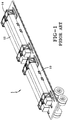
- the conventional prior art system includes a flatbed trailer 10 having a standard dimension of about 16,15 m x 2,59 m (53' x 102") and a set of missiles (not shown) inside a corresponding protective canister 12.
- Protective canister 12 may comprise any missile protective material known in the art, such as steel.
- a frame 14 is provided for securing each canister 12 to the flatbed trailer 10.
- Frame 14 may comprise any material conventional in the art, such as wood or steel.
- the conventional prior art system for the transport of missiles inside protective canisters 12 lacks any additional type of protective structure since an additional protective structure that would provide sufficient protection to the canisters 12 would be too heavy to comply with STANG 4241 and STANAG 4496 requirements and thus would cause the weight of the entire load to exceed 36.287 kg (80,000 pounds). Therefore, an additional protective structure cannot be employed and the missiles must be transported in a vulnerable manner as shown in Figure 1.
- a lightweight ballistic armor system for protection against projectiles comprising: at least one metal strike face plate comprising a plurality of slotted holes; a laminate composite backing material secured to said metal strike face plate, wherein said metal strike face plate includes a proximate metal strike face plate that is proximate to said laminate composite backing material, said proximate metal strike face plate and said composite backing material being separated by a space to define a maximum distance of 30,48 cm, wherein said metal strike face plate is a perforated metal, and wherein said metal strike face plate comprises at least one material selected from the group consisting of steel, perforated hardened steel, steel alloys, aluminum, magnesium and titanium, wherein said plurality of slotted holes are selected from the group consisting of angled slotted holes and straight slotted holes, wherein said plurality of slotted holes are set at an angle in a range of 0° - 60° relative to the vertical orientation of said metal strike face plate, and where
- Document US 2009/095147 A1 discloses an armor panel system including a strike face assemblage formed of a high-hardness material which is bonded to a fiber reinforcement.
- the high-hardness material is formed as "discrete elements" or "tiles".
- this conventional system includes a support plate and a containment element which are fixed together by a fastening structure such as stitching, clamps or bolts.
- a metallic armor assembly includes a metallic facing element with a plurality of perforations, an adhesive layer, and a composite fiber backing. Moreover, the assembly includes an encapsulating cover for encapsulating the whole assembly structure.
- FIG. 1 the armor system according to a first example ( Figure 2 ) and a second or alternative example ( Figure 3 ) is shown generally at numerals 100 and 200, respectively.
- the armor system as described herein may be employed for use in an armor trailer system, or alternatively for use as body armor, missile canisters or with a vehicle including for use with the body of a vehicle or portions thereof, as described below.
- Armor systems 100 and 200 both comprise a perforated metal strike face plate 110, 210 and a laminate composite backing 120, 220. It should be appreciated that multiple layers of both metal strike face plate and/or laminate composite backing may be employed in accordance with the present invention.
- metal strike face plate refers to a high strength metal that has a front face surface that would receive the initial impact of a projectile or shock waves or material from a blast.
- the back surface of the metal strike face plate can be adjacent to the front surface of the laminate composite backing in an example not forming part of the present invention.
- the perforated metal strike face plate provides a ballistic strike face which is the first layer of the ballistic armor or armor system that is struck by a projectile or fragment.
- the perforated metal plate 110, 210 fractures and/or rotates the projectile or fragment.
- metal strike face plate 110, 210 is provided at a thickness in the range of about 0.254 - 3.81 cm (0.10 - 1.5 inches) or even 0.635 cm - 3.81 cm (0.25 inch - 1.5 inches).
- metal strike face plate 110, 210 is provided at a thickness in the range of about 0.38 cm to 1.27 cm (0.15 inch to 0.50 inch) or even 1.27 cm - 1.59 cm (1/2 inch - 5/8 inch). It should be appreciated that the particular thickness of metal strike face plate or plates 110, 210 depends on the specific application with which the present invention is employed as discussed below.
- Perforated metal strike face plate 110, 210 may be a material that is for example, but not limited to, steel or steel alloys, hardened steel, cast irons, aluminum, magnesium, titanium and the like, or a combination thereof.
- strike face plate 110, 210 may comprise a cast iron material such as a cast steel material, i.e., ductile cast iron.
- metal strike face plate 110, 210 can be any buffer plate of a high strength material that receives impact or impact-induced stress waves prior to a shock-absorbing element.
- metal strike face plate 110, 210 can alternatively be a flat sheet of a high strength metal.
- the armor of an example may be produced and represented by the following: Styrofoam master sheets having a thickness of about 1,27 cm (0.50 inches) and dimensions of about 35,56 cm (14 inches) by about 76 cm (30 inches) are used.
- the styrofoam sheets have slots in a regular pattern produced from a die and the slots have the dimensions of 1,587 cm (0.625 inches) by 4,127 cm (1.625 inches) on 1,587 cm (0.625 inch) vertical centers and 4,127 cm (1.625 inch) horizontal centers. These slots are set at an obliquity of 30 degrees relative to a vertical orientation or axis.
- the web, defined as the solid material between the slots, is about 0,381 cm (0.150 inches) in thickness.
- An environmentally insensitive sheet or layer 704 comprising an appropriate material such as but not limited to a polymer (e.g., polypropylene) or a metal (e.g., aluminum, titanium, and the like) is applied directly onto at least one surface, such as the outwardly facing surface of layered configuration 702 exposed to external environmental conditions, or even all surfaces thereof (e.g., entirely wrapped).
- Environmentally insensitive sheet or layer 704 may be advantageously bonded or otherwise secured to layered configuration 702 by conventional methods known in the art, such as heat, pressure or bonding materials. It should also be understood that environmentally insensitive sheet or layer 704 could alternatively comprise an encasing to fully encase or enclose layered configuration.
- a process for encapsulating the laminate composite backing layer can be as follows. It should also be appreciated that the process for forming the laminate composite backing layer in accordance with the present invention would envision any alternative or modifications that would be apparent to one skilled in the art.
- a material in a liquid form is encapsulated around a fibrous bundle core in a manner conventional in the art.
- the liquid is solidified to form an encapsulating skin.
- the transformation from liquid may occur, for example, via solvent evaporation, chemical reaction, or cooling from a molten state or by any alternative comparable manner conventional in the art.
- High tensile strength polymer board may supplement the laminate composite backing 200, or replace at least a portion of the cross-sectional composition of the laminate composite backing 200.
- armor system 100 is provided with the metal strike face plate 110 and laminate composite backing 120 bonded together by bonding methods conventional in the art, such as by a urethane or polyurethane bonding. As shown in Figure 2 , metal strike face plate 110 and composite backing 120 are bonded directly together with no air space there between. It should be appreciated that metal strike face plate 110 and laminate composite backing 120 could also be secured together via mechanical means conventional in the art, as discussed further below. Such a configuration may be employed, for example, for use of the present invention in a body armor type of application.
- air space 300 is provided with an air space 300 between metal strike face plate 210 and laminate composite backing 220.
- air space 300 may be provided at a distance or depth in the range of about 0,635 cm to 12,7 cm or 15,24 cm (0.25 to 5 or 6 inches). More particularly, air space 300 may be provided at a distance or depth of about 0,634 cm to 5,08 cm (0.25 inches to 2 inches), or even about 13,02 cm (5 1/8 inches) to about 13,97 cm (5 1 ⁇ 2 inches). It should be appreciated that the particular depth of the air space would depend on the particular type of application with which the present invention is employed, including no air space at all, i.e., air space having zero cm (inches) depth.
- armor system 200 may be devoid of air space 300 in an embodiment of the invention.
- Air space 300 may be optionally filled with a foam energy absorbing material, such as low density foam, or other comparable energy absorbing material as conventional in the art.
- the armor system may be employed for use as an armor system for missile transport canisters, for body armor, for the missile canisters, or for vehicles including for incorporation into the body of the vehicle or portion(s) of the vehicle body.
- armor system is shown at numeral 100 comprising perforated metal plate 110 having plurality of holes 130, laminate composite backing 120 and air space 300 between perforated metal strike face plate 110 having plurality of holes 130 and laminate composite backing 120.
- Laminate composite backing comprises a thickness defined as thickness X, which may be for example about 0,635 cm - 12,7 cm (0.25 - 5 inches), or 0,635 cm -10,16 cm (0.25 - 4 inches), or even about 6,35 cm (2.5 inches).
- thickness X may be for example about 0,635 cm - 12,7 cm (0.25 - 5 inches), or 0,635 cm -10,16 cm (0.25 - 4 inches), or even about 6,35 cm (2.5 inches).
- FIG. 9B an alternative example of armor system is shown at numeral 100a comprising perforated metal plate 110a having plurality of holes 130a, laminate composite backing 120a and air space 300a between perforated metal plate 110a having plurality of holes 130a and laminate composite backing 120a.
- a sheet of material or board, shown at numeral 140a may be provided on top of and adjacent to laminate composite backing 120a.
- Sheet of material or board 140a may be, but is not limited to, a high tensile strength urethane board having a defined thickness of y1.
- the defined thickness of laminate composite backing 120a is thus reduced as compared to the laminate composite backing 120 of Figure 9A and is shown at numeral y2.
- the defined thicknesses of sheet of material or board 140a and laminate composite backing 120a ( Figure 9B ) is substantially equal to the thickness of laminate composite back 120 ( Figure 9A ).
- the defined thicknesses of y1 + y2 x depending on the particular application with which the present invention is employed.
- sheet of material or board 140a may be employed for partially replacing a desired thickness or amount of laminate composite backing 120a for reducing overall production costs while maintaining overall system strength, thickness and integrity. It should also be understood that multiple layers of perforated metal sheet may be employed, as discussed above, depending on a particular desirable application for the present invention with the overall thickness of the metal layer(s) being constant as desired for a particular embodiment regardless of whether a single-layer of perforated metal or multiple layers of perforated metal is/are employed.
- the armor system of the present invention meets the appropriate military weight specifications and requirements for defeating high velocity and high caliber projectiles, or alternatively for disrupting/deflecting/dissipating the energy of small arms impact (i.e., a reduction of the energy of the small arms threat).
- the armor system of the present invention meets the appropriate military weight specifications and requirements as defined by NATO Standardization Agreement (STANAG) Bullet Impact, Munitions Test Procedures promulgated on April 15, 2003 and NATO Standardization Agreement (STANAG) Fragment Impact, Munitions Test Procedures promulgated on December 13, 2006, both of which are incorporated herein by reference in their entireties.
- the present invention meets the appropriate test of stopping, or alternatively slowing down (i.e., deflecting, disrupting, dissipating the energy of) three (3) 50-caliber bullets shot within a 2-inch diameter area and shot in a time interval of 1/10 second apart.
- the armor system of the present invention comprises a weight in the range of about 87,9 - 180,9 kg/m 2 (18-35 psf) for use with missile canister protection systems. More particularly, in accordance with the present invention, the armor system comprises a weight of no greater than about 141,6 kg/m 2 (29 psf) in the embodiment in which the present invention is employed for use with a missile canister armor system. Even more particularly, in accordance with the present invention, the armor system comprises a weight of about 112,3 kg/m 2 (23 psf) in the embodiment in which the present invention is employed for use with a missile canister armor system. In accordance with the present invention, the respective weights meet those that are needed by the particular application of use with which the present invention is employed.
- the lightweight armor system of the present invention comprises a weight of about 14,6 - 73,2 kg/m 2 (3-15 psf), including about 29,3 - 53,7 kg/m 2 (6-11 psf). More particularly, the lightweight armor system of the present invention comprises a weight in the range of about 34,2 - 53,7 kg/m 2 (7-11 psf), or even 34,7 - 52,7 kg/m 2 (7.1-10.8 psf), when employed with a metal strike plate, such as steel or titanium, for defeating, for example, 0.30 caliber armor piercing threats. In accordance with the present invention, the respective weights meet those that are needed by the particular application of use with which the present invention is employed.
- the lightweight armor system of the present invention comprises a weight in the range of about 19,5 - 39,1 kg/m 2 (4-8 psf), or even about 24,4 -29,3 kg/m 2 (5-6 psf), or more particularly about 27,3 kg/m 2 (5.6 psf), when employed with a hardened steel plate for defeating threats such as 5.56 X 45 M193 and SS 109 (M855 equivalent).
- the embodiment of the present invention may be employed for use with vehicles, such as a material for forming at least a portion of the vehicle body, such as a police vehicle or military vehicle.
- Ultrahigh Molecular Weight Polyethylene UHMWPE
- UHMWPE Ultrahigh Molecular Weight Polyethylene
- the lightweight armor system of the present invention comprises a weight in the range of about 13,5 - 43,9 kg/m 2 (4-9 psf), or even about 19,5 - 37,6 kg/m 2 (4-7.7 psf), or more particularly about 19,5 - 32,7 kg/m 2 (4.0-6.7 psf), or even more particularly in the range of about 21 - 30,7 kg/m 2 (4.3-6.3 psf) or still even more particularly about 19,5 - 26,9 kg/m 2 (4.0-5.5 psf), when employed for use as a missile canister for encasing and protecting missiles during transport.
- S-Glass may be advantageously employed as the component of the composite backing, such as for lowering flammability properties.
- the fibers or composite material may be advantageously used to wrap the perforated metal plate directly.
- the wrapped perforated strike plate can be used as a singular item for improving ballistic and/or environmental properties.
- a mechanical attachment mechanism 400 can be fabricated into the components 110 and 120 for attaching components 110 and 120 to each other and/or for attaching an armor system to another object to be protected, such as a vehicle, and which is employed with the specific application of use.
- metal strike face plate 110 comprises recessed pockets 42 through which tubular spacers 40, each having a threaded end 41 passes through.
- Metal strike face plate 110 is attached to a structure 13 to be protected (e.g., a vehicle) ( Figure 8 ) through tubular spacers 40 by a washer 30 and nut 32.
- metal strike face plate 110 comprises an opening 45 through which tubular spacer 40 may be accommodated.
- mechanical attachment mechanism 400 may be a conventional threaded screw and nut engagement mechanism as known in the art.
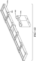
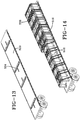
- FIGs 10-14 an exemplary use of the armor system in accordance with the present invention in connection with a particular type of application will be shown and described, namely for use with an armor system for the transport of missile canisters. It should be appreciated, however, that the specific application of the present invention shown in Figures 10-14 is for illustrative purposes only and the armor system of the present invention should not be considered limited or exclusive to such an application or use. As indicated above, the present invention may alternatively and advantageously be employed for use with body armor, missile canisters, or the vehicle body itself or a portion or portions of the vehicle body as within the scope of the present invention.
- An additional frame system 516 such as an aluminum frame system ( Figure 11 ) having a top frame 516a and side frames 516b, is provided for securing the armor system panels 518 to the side of the flatbed truck trailer 510 and totally surrounding the canisters 512 secured by frame 514.
- frame system 516 any comparable material to aluminum may be employed for frame system 516.
- each segment of frame system 516 contains or houses strike face plate 520 and laminate composite backing 524, with air space 522 therebetween, and regardless of whether the respective segment of frame system 516 is employed on a side, front, top or back of the trailer bed 510.
- Each segment of frame system 516 is employed in series so as to directly and securely abut the respective adjacent segment of frame system 516 to form a secure protective system in all directions surrounding the canisters 512, including top and all sides.
- the Ballistic Barrier Test was conducted in order to test ballistic armored panels in accordance with the present invention.
- Projectile velocities were measured using Oehler infrared screens and high-speed video.
- the Oehler screen and Phantom high-speed camera setup was as shown in Figure 18 .
- the target plate was secured to the test stand.
- the target plate consisted of a 1,587 cm (5/8-inch) perforated grate up-range and a 6,35 cm (2.5-inch) thick piece of composite down-range.
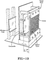
- the target panels were bolted to the test stand as shown in Figure 19 .
- the distance from the perforated plate to the composite plate was approximately 13,02 cm (5 1/8-inches).
- Velocity data for this volley is shown in Table 2 below.
- Another target test plate in accordance with the present invention was secured in a similar fashion as the first test plate.
- the difference between the respective plates was that the former had a composite plate thickness of 4,44 cm (1.75 inches). This required the use of a 1,9 cm (3 ⁇ 4-inch) standoff directly behind and down-range of the composite plate in order to maintain a plate separation of 13,02 cm (5 1/8-inches) as shown in Figure 22 .
- the objective of the test was to impact each candidate plate in a specified quadrant with a single North Atlantic Treaty Organization (NATO) standardized fragment with a nominal mass of 18.6 grams, traveling at a velocity of 2530 +/- 91 m/s (8300 +/-300 ft/s).
- NEO North Atlantic Treaty Organization
- the fragment was fired from a 40mm High-Performance Powder Gun, which is an electrically-actuated, mechanically-fired cannon.
- a schematic depiction of the test site is shown in Figure 26 .
- the instrumentation setup was as set forth as shown in Figure 27 .
- the additional test plate in accordance with the present invention was installed with the same standoff used for the bullet impact portion of the test. A distance of 13,02 cm (5 1/8-inches) was measured from the back side of the grate to the face of the composite plate as shown in Figure 32 .
- the velocity was measured using one primary and one redundant Phantom camera.
- the fragment velocity data is presented in the following Table 7.
- the tests were conducted in accordance with the approved test parameters.
- the projectile velocities and firing intervals for the bullet impact test were in accordance with STANAG 4241.
- the projectile velocity for the fragment impact test was in accordance with STANAG 4496.
- the armor system in accordance with the present invention may be employed in any type of appropriate application for protection against high velocity and high caliber projectiles.
- Such applications for employment may include, but is not limited to, individual protective systems, i.e., body armor, armor for tanks, armor for ships or boats, armor for trucks, armor for vehicles, armor for aircraft including airplanes, jets and helicopters, armor for barriers, armor for protective structures, i.e., blast panels and armor for missile containers for storage or transport.
- FIG 34 an alternative example of the armor system will be shown and described, namely for use with an armored structure, such as an armored trailer or armored shipping container and the like in which the armor system is integrally built into the respective walls, floors and ceiling of the armored structure, such as an armored trailer or armored shipping container.
- an armored structure such as an armored trailer or armored shipping container and the like in which the armor system is integrally built into the respective walls, floors and ceiling of the armored structure, such as an armored trailer or armored shipping container.
- the armored structure as depicted in Figure 34 is an armored trailer.
- the armored structure is not limited to an armored trailer but can include other types of structures requiring an integral armor system including but not limited to an armored shipping container.
- all of opposing walls 612a, 612b, ceiling or roof 614, rear end 616, front end 618 and, optionally, floor 620 comprise the armor system of the present invention discussed herewith integrally formed within the parameters of flatbed semi-truck trailer 610.
- the aforementioned described framework system is omitted in the instant alternative example and the ballistic armor system is employed directly and integrally into each of opposing walls 612a, 612b, ceiling or roof 614, rear end 616, front end 618 and, optionally, floor 620 thereby forming a singular and unitary armored trailer system 600 having the ballistic armor system of the present invention integrally formed into armored trailer system 600.
- alternative comparable structures may be employed such as but not limited to armored shipping containers, armored boxes, armored rooms, armored shelters and the like.
- metal strike face plate may be omitted in armored trailer system 600 depending on the required level of protection desired for the particular cargo being protected.
- the airspace according to armored trailer system 600 may be in the range of about 0 cm (inches) (i.e., negligible or no airspace) to about 25,4 cm (10 inches).
- the rear composite layer of armored trailer system 600 may comprise any material as described above, including but not limited to polyethylene, aramid- or glass-based composite materials. In accordance with the present invention, the respective weights meet those that are needed by the particular application of use with which the present invention is employed.
Landscapes
- Engineering & Computer Science (AREA)
- General Engineering & Computer Science (AREA)
- Ceramic Engineering (AREA)
- Chemical & Material Sciences (AREA)
- Aiming, Guidance, Guns With A Light Source, Armor, Camouflage, And Targets (AREA)
Description
- The present invention generally relates to lightweight ballistic armor systems which can be integrally formed within, or secured to, a structure, such as a trailer, shipping containers, and the like, for protecting individuals, structures, missile canisters, vehicles and the like against low, medium and high velocity and low, medium and high caliber projectiles, as well as systems and structures, such as trailers, shipping containers, vehicles, body armor, aircraft, missile canisters and the like being integrally formed of such a lightweight ballistic armor system. More particularly, the present invention relates to an enhanced ballistic armor system which is integrally formed within a structure or vehicle, or secured directly thereto, for protection of individuals, structures, vehicles, cargo and the like against low, medium and high velocity and low, medium and high caliber projectiles. These projectiles can include low-caliber to high-caliber bullets, rockets, exploding grenades, exploding mortar shells, exploding mines and the like.
- Ceramic-based armors and armor systems are well known in the art. However, many conventional armors and armor systems tend to be too heavy and/or bulky to be easily employed as a protection system against high caliber artillery and projectiles, or even lower caliber threats. Moreover, many conventional armors and armor systems can also tend to be too expensive for practical use or manufacture. Furthermore, ballistic armor and armor systems are subjected to a variety of projectiles or fragments over a wide range of velocities and calibers designed to defeat the armor or armor systems by penetrating the armor or armor systems, or by causing an impact against the armor or armor system that can cause spalling (i.e., flaking off of material from an object due to impact from another object), in particular spalling through mechanical stress which in turn eventually defeats the armor.
- Many and various types of armor and armor systems are known for protecting personnel, vehicles, equipment and the like from damage or destruction caused by high caliber artillery and projectiles. Many such armor and armor systems are employed in military applications to protect individuals (such as via body armor), aircraft, tanks, ships and vehicles from damage or destruction caused by high caliber artillery and projectiles. In yet other applications, many such armor and armor systems are employed in military applications to protect missiles during their storage or transport, such as for example in the form of canisters in which the missiles are stored, held or transported.
- The use of such armor and armor systems for protecting missiles maintained in protective canisters during storage or transport of the missiles is also well known. However, munitions must comply with the MIL-STD-2105 bullet impact and fragment impact requirements as defined in STANAG 4241 and STANAG 4496. Meeting these requirements by protecting the munitions with conventional ceramic armor systems is difficult due to the limited multi-hit performance of ceramic systems. In some known applications, the armor or armor systems is incorporated into the structure that is to be protected. Such applications can include military vehicles, armored vehicles or missile storage canisters. In such applications, it is typically not possible for the armor or armor systems to be temporarily applied but rather thus tend to be permanent aspects of the structure. In this regard, the armor systems can be difficult or even impossible to replace in the event of damage or failure.
- In order to address the issue of weight in armor or armor systems, some conventional systems employ ceramic materials that can protect against a range of projectiles or fragments of projectiles. Ceramic tiles can often be used to break up and dissipate the energy of high caliber projectiles, and can be applied in specific thicknesses or patterns of the arrangement of tiles to maximize effectiveness. However, a disadvantage of conventional ceramic tiles is that ceramic is brittle and is more susceptible to cracking after impact, thus reducing the effectiveness against subsequent impacts. Cracking of the conventional ceramics can also leave the underlying structure to be protected vulnerable to exposure to outside elements, such as water, air, heat, cold, wind, chemicals, biological agents, etc., thereby further weakening the structure to be protected.
- One known disadvantage in certain conventional armored applications is the allowable road weight that limits the numbers of encased missiles from being transported together. Due to the strict road weight limits, the excessive load created by the combined weight of the missiles, truck, etc. allows for only a few (e.g., 1-4) missiles to be transported together. For example, the Department of Transportation (DOT) has established that the total road weight of a truck, including the weight of the load, cannot exceed 36.287 kg (80,000 pounds) per vehicle. It should of course be understood that different trucks have different weights, while the specific weight of the particular load, such as missiles to be transported and the respective container or canister, can vary depending on the nature of the type of missile at issue. Typically, the combined weight of a single missile and the respective canister may be about 3.402 kg (7,500 pounds). Nevertheless, the combined weight of the truck and the missiles being transported which comprise the respective load cannot exceed 36.287 kg (80,000 pounds). Consequently, the missiles are oftentimes unprotected (i.e., lack a protective structure) in order to maximize the number of missiles that are transported together while also meeting the strict road weight limits or only have the standard protective canisters without additional protective means. Oftentimes, the excessive load caused by the combined weight of the missiles and storage protective canister allows for just one, or at most two, missiles to be transported together. In the event more missiles are transported, such as 3-4, the transport might be done in a manner without any additional protection in which case the missiles are vulnerable to attack. To achieve the requirement of not exceeding the 36.287 kg (80,000 pound) load limit, the protective system of the present invention in an embodiment may be provided at a weight in the range of about 87,9 - 146,5 kg/m2 (18 - 30 lb. / square foot (psf)). However, it should be appreciated that the specific weight per m2 in accordance with the present invention depends on the specific nature of the application type with which the present invention is employed.
- Another disadvantage with conventional armor systems in the case of armor systems employed as protection for vehicles is that the excessive weight of the armor systems can tend to render the vehicles relatively immobile, or at least significantly slower. This in turn can tend to cause the vehicles to be more vulnerable to attacks by high velocity and high caliber projectiles, and more significantly more vulnerable to attack, and even more significantly more vulnerable to repeated attacks by projectiles or fragments of projectiles.
- In some known applications, the armor or armor systems is incorporated into the structure that is to be protected. Such applications can include military vehicles, armored vehicles or missile storage canisters. In such applications, it is typically not possible for the armor or armor systems to be temporarily applied but rather are aspects of the structure. In this regard, the armor systems could be difficult to replace in the event of damage or failure.
- Projectiles, such as armor piercing ammunition, are designed to specifically penetrate conventional armor and armor systems. Conventional ceramic-faced armor systems were consequently developed to defeat armor piercing ammunition. For example, at impact, the projectile can be blunted or otherwise damaged by the conventional ceramic-faced armor system. At the same time, cracking or other damage to the conventional ceramic-faced armor system is inevitable which leads to a weakening of the integrity of the conventional ceramic-faced armor system and thus more vulnerable to future attacks.
- Some specific examples of conventional prior art armor and armor systems are now set forth below.
- Document
US 2009/0320676 A1 is directed to the use of an armor for protection against projectiles having a ceramic layer with a confinement layer on the front thereof. The ceramic layer is backed by a first metallic layer and the first metallic layer in turn is backed by a composite layer. The composite layer is backed by a second metallic layer, which in turn is backed by an anti-trauma layer. - Document
W0 91/00490 A1 - Document
US 4 061 815 A discusses a laminated sheet material having high impact resistance for use in with armor plates. One or more layers of cellular or non-cellular polyurethane is sandwiched between a rigid, high impact resistant sheet of material, such as aluminum armor plate and fiberglass, in the one face and a thin retaining skin on the other. A filler, such as ceramic, particulate refractory or strip metal, can be embedded in the polyurethane layer(s). - Document
US 2010/0212486 A1 discusses a strike plate including a base armor plate having an outwardly facing surface and a hard layer deposited on the base armor plate to substantially overlay the outwardly facing surface. A ballistic attenuation assembly is allegedly provided having multiple sheets of a first fibrous material and a sheet of a second fibrous material laminated together by a modified epoxy resin with the first sheet of a second fibrous material being exposed along an outward facing surface. An alternative ballistic attenuation assembly is also discussed having a first panel having opposed inward and outward facing surfaces, a second panel having opposed inward and outward facing surfaces, and a spacer interposed between the first and second panels forming a gap between the inward facing surfaces of the first and second panels. - Document
US 5 200 256 A discusses an armor lining for protecting objects from high velocity projectiles having an extended sheet-like body having a weight of less than eight pounds per square foot and having an inner strike surface being positioned away from the object to be protected. A first layer of woven fabric material is carried at a position adjacent the outer strike surface layer and a second layer of material is carried internally of the woven layer between the outer strike surface and an inner attachment surface. A third layer of energy absorbent material is positioned adjacent the inner attachment surface and interfaces with the second fabric layer. - Document
US 2009/0293709 A1 discusses an armor system for protecting a vehicle from high energy projectiles having a leading layer, relative to the projectile trajectory, positioned exterior to the hull, a first plurality of sheet-like layers of a low density material positioned between the leading layer and the hull; and a second plurality of sheet-like high strength metal layers positioned between the leading layer and the hull. The individual ones of the first plurality of high strength metal layers are positioned alternating with and to the rear of individual ones of the second plurality of low density material layers. The leading layer can be one of a sheet-like metallic layer, a metalicized grid layer, and the outer-most layer of the first plurality of low materials layers. The materials of the high strength metal layers can be steel and high strength aluminum, and the materials of the low density material may be low density polypropylene composites and R-Glass composites. - Document
US 2010/0294123 A1 discusses a modular armor system having a leading layer with a metal and an intermediate sheet-like layer of a low density material lesser than that of metal, abutting a rear surface of the leading layer. The armor system also has an intermediate sheet-like layer having glass fiber material and abutting a rear surface of the intermediate low density material layer, and an intermediate sheet-like layer having metal and abutting a rear surface of the intermediate glass fiber layer. -
Document US 4 836 084 A discusses an armor plate composite having four main components, namely, a ceramic impact layer, a sub-layer laminate, a supporting element and a backing layer. The ceramic layer serves for allegedly blunting the tip of a projectile. The sub-layer laminate of metal sheets alternate with fabrics impregnated with a viscoelastic synthetic material for absorbing the kinetic energy of the projectile by plastic deformation. The backing layer away from the side of impact consists of a pack of impregnated fabrics. - Document
US 2006/0065111 A1 discusses an armor system having an outer case of woven or unidirectional fibers filled with one or more protective materials. The outer case includes a pressure sensitive adhesive bonded to one side for allegedly quick and easy application to a body to be protected. The protective materials may include ceramic material which may be in the form of ceramic tile sheets, loose ceramic balls or perforated tiles, multiple layers of woven or unidirectional cloth and steel mesh. - With reference to
Figure 1 , an example of a conventional prior art protective system for transporting missiles is shown and referenced generally atnumeral 1. As shown inFigure 1 , the conventional prior art system includes aflatbed trailer 10 having a standard dimension of about 16,15m x 2,59 m (53' x 102") and a set of missiles (not shown) inside a correspondingprotective canister 12.Protective canister 12 may comprise any missile protective material known in the art, such as steel. Aframe 14 is provided for securing eachcanister 12 to theflatbed trailer 10.Frame 14 may comprise any material conventional in the art, such as wood or steel. As depicted inFigure 1 , the conventional prior art system for the transport of missiles insideprotective canisters 12 lacks any additional type of protective structure since an additional protective structure that would provide sufficient protection to thecanisters 12 would be too heavy to comply with STANG 4241 and STANAG 4496 requirements and thus would cause the weight of the entire load to exceed 36.287 kg (80,000 pounds). Therefore, an additional protective structure cannot be employed and the missiles must be transported in a vulnerable manner as shown inFigure 1. - Document
US 2014/0013934 A1 on which the preamble ofclaim 1 is based discloses a lightweight ballistic armor system for protection against projectiles comprising: at least one metal strike face plate comprising a plurality of slotted holes; a laminate composite backing material secured to said metal strike face plate, wherein said metal strike face plate includes a proximate metal strike face plate that is proximate to said laminate composite backing material, said proximate metal strike face plate and said composite backing material being separated by a space to define a maximum distance of 30,48 cm, wherein said metal strike face plate is a perforated metal, and wherein said metal strike face plate comprises at least one material selected from the group consisting of steel, perforated hardened steel, steel alloys, aluminum, magnesium and titanium, wherein said plurality of slotted holes are selected from the group consisting of angled slotted holes and straight slotted holes, wherein said plurality of slotted holes are set at an angle in a range of 0° - 60° relative to the vertical orientation of said metal strike face plate, and wherein said laminate composite backing material comprises a thickness in the range of 0,254 cm to 10,16 cm (0,1 to 4 inches). - Document
US 2009/095147 A1 discloses an armor panel system including a strike face assemblage formed of a high-hardness material which is bonded to a fiber reinforcement. The high-hardness material is formed as "discrete elements" or "tiles". Furthermore, this conventional system includes a support plate and a containment element which are fixed together by a fastening structure such as stitching, clamps or bolts. - Finally, document
US 2004/216595 A1 discloses an armor assembly, wherein a metallic armor assembly includes a metallic facing element with a plurality of perforations, an adhesive layer, and a composite fiber backing. Moreover, the assembly includes an encapsulating cover for encapsulating the whole assembly structure. - It is an object of the present invention to provide a lightweight ballistic armor system, a body armor system, an armored vehicle system, a missile canister armor system and an armored structures system which is robust against extreme temperatures, humidity, thermal shock, fluids, radiation, fungus etc. while still being light weight and having good protection capabilities.
- According to the present invention this object is achieved by the characterizing features of the
independent claims - The dependent claims define advantageous embodiments of the present invention.
- It is to be understood that both the foregoing general description and the following detailed description are exemplary and explanatory only and are intended to provide a further explanation of the present invention, as claimed.
-
-
Figure 1 is a perspective view of a prior art missile container transport system. -
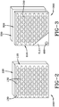
Figure 2 is a perspective view of an example of an armor system. -
Figure 3 is a perspective view of a further example of an armor system. -
Figure 3A is a cross-sectional view of the example of the armor system as shown inFigure 3 . -
Figure 3B is a perspective view of the example of the armor system as shown inFigures 3 and3A . -
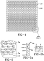
Figure 4 is a front view of an example of a perforated metal strike face plate. -
Figure 5 is an exploded schematic view of a portion of the perforated metal strike face plate as shown inFigure 4 . -
Figure 5A is a cross-sectional view of a portion of the perforated metal strike face plate taken in the direction 5A-5A inFigure 5 . -
Figure 5B is a schematic view of a portion of the perforated metal strike face plate taken in the direction B-B inFigure 5 . -
Figure 6 is a cutaway cross-sectional view of an example of the metal strike face plate. -
Figure 7 is a cutaway cross-sectional view of an alternative example of a metal strike face plate. -
Figure 8 is a perspective view of a further example of a metal strike face plate. -
Figure 9A is a cross-sectional view of an example of the layers of an armor. -
Figure 9B is a cross-sectional view of an alternative example of the layers of an armor system. -
Figure 10 is an exploded perspective view of an example of an armor system in an exemplary application of use thereof being a missile transport system. -
Figure 11 is a rear view of the armor system in an example application of use as shown inFigure 10 . -
Figure 12 is an exploded perspective view of a frame system for use with the armor system in an example application of use as shown inFigure 10 . -
Figure 13 is a perspective view of a flatbed truck trailer for use with the armor system in an example application of use as shown inFigure 10 . -
Figure 14 is a perspective view of the armor system in an alternative example application of use. -
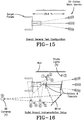
Figure 15 is a schematic drawing of a test configuration of the present invention. -
Figure 16 is a schematic drawing of a bullet impact instrumentation configuration of the present invention. -
Figure 17 is a schematic drawing of the gun barrel arrangement of the test configuration of the present invention. -
Figure 18 is a schematic drawing of the velocity screen arrangement of the test configuration of the present invention. -
Figure 19 is a perspective schematic drawing of the plate arrangement of the test configuration of the present invention. -
Figure 20 is a schematic drawing of the plate projectile impact locations of the test configuration of the present invention. -
Figure 21 is a schematic drawing of the post-test plate condition of the test configuration of the present invention. -
Figure 22 is a schematic drawing of the test plate shown secured to the target stand of the test configuration of the present invention. -
Figure 23 is a schematic drawing of the projectile impact locations of the test configuration of the present invention. -
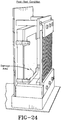
Figure 24 is a schematic drawing of the post-test plate condition of the test configuration of the present invention. -
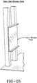
Figure 25 is a schematic drawing of the witness plate of the test configuration of the present invention. -
Figure 26 is a schematic drawing of a fragment impact test configuration of the present invention. -
Figure 27 is a schematic drawing of the fragment impact test instrumentation configuration of the present invention. -
Figure 28 is a schematic drawing of the fragment impact target points. -
Figure 29 is a schematic drawing of the test plate configuration pre-fragment impact test of the present invention. -
Figure 30 is a schematic drawing of the test plate post-fragment impact test of the present invention. -
Figure 31 is a schematic drawing of the witness plate post-fragment impact test of the present invention. -
Figure 32 is a schematic side view of the plate configuration during the fragment impact test of the present invention. -
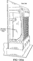
Figure 33A is a schematic side view of the plate configuration post-fragment impact test of the present invention. -
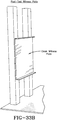
Figure 33B is a schematic side view of the witness plate post-fragment impact test of the present invention. -
Figure 34 is a perspective view of a semi-truck trailer for use with an armor system wherein the armor system is integrally formed within the parameters of the flatbed truck trailer. -
Figure 35 is a perspective view of an example not forming part of the present invention. -
Figure 36 is a perspective view of the embodiment in accordance with the present invention. - The present invention is now described with reference to the drawings, wherein like reference numerals are used to refer to like elements throughout. In the following description, for purposes of explanation, numerous specific details are set forth in order to provide a thorough understanding of the present invention. It will be evident, however, to one skilled in the art that the present invention may be practiced without these specific details.
- Turning now to
Figures 2, 3 ,3A and 3B , the armor system according to a first example (Figure 2 ) and a second or alternative example (Figure 3 ) is shown generally atnumerals Armor systems strike face plate composite backing perforated metal plate strike face plate strike face plate plates - Perforated metal
strike face plate face plate strike face plate strike face plate Class 2 armor), that MIL-A-12560 rolled homogenous steel (Class 1a armor) and MIL-A-46100 high hard rolled homogenous steel armor (Class 1b armor) is acceptable for imparting a hole pattern into to make perforated plate. These are examples of perforated material types which are qualified to date and are by no means comprehensive. It should be appreciated by the skilled artisan that other candidate alloys for making cast perforated plates may exist. - In an alternative example, a composite layer or
metal skin layer 211 may optionally cover the perforated metalstrike face plate 210 as shown inFigures 3 and7 . Composite layer ormetal skin layer 211 is depicted only in the example ofFigure 3 (i.e., armor system 200), but it should be appreciated that composite layer ormetal skin layer 211 may be employed with the example as shown inFigure 2 as well (i.e., armor system 100) or any other example of the present invention as discussed below. It should also be appreciated that composite layer ormetal skin layer 211 covers the entire front surface of metalstrike face plate 210, but only a cut-away portion of composite layer ormetal skin layer 211 is depicted inFigure 3 for illustrative purposes only. The optional, thin metal skin layer provides reinforcement protection against any projectile effect and aids in the breakup of a projectilestriking armor systems strike face plate 210. - In accordance with the present invention, composite layer or
metal skin layer 211 may be a material that is the same as or different from the material of metalstrike face plate 210. As understood fromFigure 3 , composite layer ormetal skin layer 211 comprises a thickness that is relatively thin and is thinner than the thickness of metalstrike face plate 210. In particular, composite layer ormetal skin layer 211 can comprise a thickness in the range of from about 0,079 cm to 0,635 cm (1/32 inch to ¼ inch), or even 0,317 cm to 0,635 cm (1/8 inch - ¼ inch). - As shown in
Figures 2-5 , metalstrike face plate Figure 3 ) which are set at an oblique angle relative to the vertical orientation of perforated metalstrike face plate holes strike face plate holes strike face plate - As shown in
Figure 6 , a cutaway cross-sectional view of perforated metalstrike face plate 110 is provided along line a - a' ofFigure 8 . As depicted inFigure 6 , perforated metalstrike face plate 110 comprises a plurality of oblique-angled holes or slots. Still referring toFigures 2 and 3 , metalstrike face plate perforations Figure 4 , plurality ofholes 130 is uniformly distributed along the entire front face ofstrike face plate 110.Holes holes strike face plate holes Figure 5 ) whose width and thicknesses can be varied as necessary, but are uniformly distributed throughout. Perforatedmetal strike face composite backing - The sizes of the openings of the slots which may be advantageously used in embodiments of the present invention range from about 0,381 cm to 5,08 cm (0.15 inch to about 2 inches) in length, or even about 1,27 cm to 5,08 cm (0.50 inch to about 2.0 inches) in length for an embodiment (i.e., the vertical orientation of the openings of the slots), by about 0,381 cm to 5,08 cm (0.15 inches to about 2 inches), or even about 0,635 cm to 2,54 cm (0.25 inch to about 1.0 inch) in width for an embodiment in width (i.e., the horizontal orientation of the openings of the slots). The
web 132, defined as the solid material between the plurality of slots orholes Figures 5A, 5B ) with each hole angled at about 20°-30° relative to the vertical orientation of the present invention, and more particularly at about 25° relative to the vertical orientation of the present invention. It should also be appreciated that the number, size, arrangement, angle, and the like of the holes employed in accordance with the present invention may depend on the use of perforated metal for the strike face plate, and which may be left for the skilled artisan to determine depending on the nature of the particular application with which the present invention is employed. - The armor of an example may be produced and represented by the following: Styrofoam master sheets having a thickness of about 1,27 cm (0.50 inches) and dimensions of about 35,56 cm (14 inches) by about 76 cm (30 inches) are used. The styrofoam sheets have slots in a regular pattern produced from a die and the slots have the dimensions of 1,587 cm (0.625 inches) by 4,127 cm (1.625 inches) on 1,587 cm (0.625 inch) vertical centers and 4,127 cm (1.625 inch) horizontal centers. These slots are set at an obliquity of 30 degrees relative to a vertical orientation or axis. The web, defined as the solid material between the slots, is about 0,381 cm (0.150 inches) in thickness.
- As shown in
Figures 2 and 3 , plurality ofholes holes holes - With specific reference to
Figure 7 , an alternative example of the perforated metalstrike face plate 210 havingthin metal skin 211 over the facing of perforated metal or expanded metalstrike face plate 210 is provided. Plurality ofholes 230 is shown having an oblique-angled configuration relative to a vertical orientation or axis. In particular, plurality ofholes 230 may comprise an oblique-angle configuration of about between 20°- 60° relative to the vertical orientation of the metalstrike face plate 210. More particularly, plurality ofholes 230 may comprise an oblique-angle configuration of about 25° relative to the vertical orientation of the metalstrike face plate 210. Of course, plurality ofholes 230 may even be straight. Onto composite layer ormetal skin layer 211, a further optionalhard surface material 212 can be placed. The additional hard facedmaterial 212 may be composed of carbon cloth, tungsten carbide particles, FeCr coating, FeCr-/Mo/V surfacing, 1642 CrC surfacing or Ceramo Cr7Cr3 surfacing and can be employed to provide an additional protective layer. The hard faced material may be sintered to the thin composite layer ormetal skin layer 211 during the casting process and aids in the breakup of a high caliber projectile. - With reference to
Figures 2 and 3 ,armor system Figure 3 ). Laminatecomposite backing composite backing composite backing 200 comprises a thickness of about 1,27 cm - 7,62 cm (0.5-3 inches), or even about 6,35 cm (2.5 inches), in accordance with the embodiment of the present invention. It should be appreciated, however, that the particular thickness of the laminate composite backing depends on the particular type of application with which the present invention is used. For example, use of the laminate composite backing in an armor system according to the present invention would be comparatively thinner for use with body armor than for use with, for example, an armor system for protecting vehicles or missile transport canisters. - In accordance with an example of the present invention, laminate
composite backing composite backing composite backing - Alternatively, the optional encasing or encapsulation in accordance with an example may be replaced by employing an environmentally insensitive layer or wrap, such as a polymer layer, sheet, or encasing (e.g., polypropylene) or a metal layer, sheet, or encasing (e.g., aluminum, titanium, and the like). One such example not forming an embodiment of the present invention is shown generally at numeral 700 in
Figure 35 . As shown inFigure 35 ,armor system 700 includes a layered configuration of perforated metal andcomposite backing 702, shown as adjacent to each other. An environmentally insensitive sheet orlayer 704, comprising an appropriate material such as but not limited to a polymer (e.g., polypropylene) or a metal (e.g., aluminum, titanium, and the like) is applied directly onto at least one surface, such as the outwardly facing surface oflayered configuration 702 exposed to external environmental conditions, or even all surfaces thereof (e.g., entirely wrapped). Environmentally insensitive sheet orlayer 704 may be advantageously bonded or otherwise secured to layeredconfiguration 702 by conventional methods known in the art, such as heat, pressure or bonding materials. It should also be understood that environmentally insensitive sheet orlayer 704 could alternatively comprise an encasing to fully encase or enclose layered configuration. As shown inFigure 35 , an optional molding, edging orframe 706 comprising a material such as but not limited to a glass epoxy composite (or a comparable conventional protective material) may advantageously be provided around the outside edges oflayered configuration 702 having sheet orlayer 704 bonded or secured thereon for reinforcinglayer 704 onto layeredconfiguration 702. Of course,frame 706 may also be employed in the case of an environmentally insensitive material fully encases or wrapslayered configuration 702. It should be appreciated thatframe 706 is optional for providing additional reinforcement and/or ballistic characteristics toarmor system 700. - Turning now to
Fig. 36 , the embodiment of the present invention is shown and described. As discussed above, the optional encasing or encapsulation in accordance with an example may optionally be replaced by employing an environmentally insensitive layer or wrap, such as a polymer layer, sheet, or encasing (e.g., polypropylene) or a metal layer, sheet, or encasing (e.g., aluminum, titanium, and the like). This embodiment armor system is shown generally at numeral 800 inFigure 36 . As shown inFigure 36 ,armor system 800 includes acomposite backing 802 having an environmentally insensitive sheet orlayer 804, comprising an appropriate material such as but not limited to a polymer (e.g., polypropylene) or a metal (e.g., aluminum, titanium, and the like) applied directly onto at least one surface, such as the outwardly facing surface oflayered configuration 802 exposed to external environmental conditions, or even all surfaces thereof (e.g., entirely wrapped). Environmentally insensitive sheet orlayer 804 may be advantageously bonded or otherwise secured tocomposite backing 802 by conventional methods known in the art, such as heat, pressure or bonding materials. As shown inFigure 36 , an optional molding, edging orframe 806 comprising a material such as but not limited to a glass epoxy composite (or a comparable conventional protective material) may advantageously be provided around the outside edges ofcomposite backing 802 having sheet orlayer 804 bonded or secured thereon for reinforcinglayer 804 ontocomposite backing 802. It should be appreciated thatframe 806 is optional for providing additional reinforcement and/or ballistic characteristics toarmor system 800. As also shown inFig. 36 ,armor system 800 also includes at least one layer ofperforated metal 803 adjacent tocomposite backing 802 relative to the external environment at a distance as described above. - It should be appreciated that a process for encapsulating the laminate composite backing layer can be as follows. It should also be appreciated that the process for forming the laminate composite backing layer in accordance with the present invention would envision any alternative or modifications that would be apparent to one skilled in the art. In particular, a material in a liquid form is encapsulated around a fibrous bundle core in a manner conventional in the art. The liquid is solidified to form an encapsulating skin. The transformation from liquid may occur, for example, via solvent evaporation, chemical reaction, or cooling from a molten state or by any alternative comparable manner conventional in the art. For example, a two-component system which is liquid under normal ambient conditions without the addition of a solvent can be poured over the fibrous bundle core and the components solidify by a chemical reaction. Alternatively, a thermoplastic material can be melted and molded around the fibrous bundle core, i.e., by insert injection molding.
- Regardless of the actual chemistry of the resin material, the preferred material properties of the resultant solidified optional encapsulating skin for the laminate composite backing in accordance with the present invention can be the following. In particular, thermoset elastomeric resins may be employed in accordance with the present invention as follows.
- Hardness, via ASTM D 2240: Shore 60A-60D, preferably 75A-55D;
- Ultimate Tensile Strength (psi), via ASTM D 412: 8,27 MPa - 62,05 MPa (1200-9000 psi), preferably 20,68 MPa - 55,16 MPa (3000-8000 psi);
- Modulus at 100% elongation (psi), via ASTM D412: 2,76 MPa - 15,17 MPa (400-2200 psi), preferably 4,82 MPa - 10,34 MPa (700-1500 psi);
- Modulus at 300% elongation (psi), via ASTM D412: 4,82 MPa - 34,47 MPa (700-5000 psi), preferably 6, 2 MPa - 27,58 MPa (900-4000 psi);
- Elongation-to-break (%), via ASTM D412: 150-1000, preferably 300-800.
- An example of the formulation can be as follows. It should be appreciated that the formation is not limited to this example, but would envisions any alternatives or modifications that would be understood by one skilled in the art. A polyurethane that is made by the reaction of a multifunctional amine and a multifunctional isocyanate without the addition of a solvent is provided. More specifically, an oligomeric ether or ester with diamine functionality reacted with a diisocyanate is provided.
- As discussed above, alternatively the bundle or layered composite configuration may be environmentally protected by pressing or wrapping protective layers of polypropylene or other comparable materials, such as metal, Kevlar, S-glass, and the like, around the bundle or layered composite configuration. Edges may be reinforced with glass epoxy composites or other comparable protective and/or reinforcement materials as shown in
Fig. 36 . It should therefore be understood that in accordance with the embodiment of the present invention, embodiments for lower weight systems of the present invention may be advantageously used for example in connection with "on canister" ballistic systems for protecting missile canisters. In that case, it should be understood that such embodiments may include at least one metal strike face plate against a corresponding composite backing with or without a polypropylene or other protection layer and with or without a corresponding frame for reinforcing. - In an example, as discussed in greater detail below, a layer, sheet or board of a high tensile strength material, such as a high tensile strength polymer board, may be employed adjacent to laminate
composite backing 200 at a thickness in the range of about 0,079 cm - 10, 16 cm (1/32 inch - 4 inches), or about 0,317 cm (1/8 inch) to about 10,16 cm (4 inches), or about 0,635 cm (¼ inch) to about 10,16 cm (4 inches), or even about 0,16 cm - 10,16 (1/16 inch - 4 inches) and more particularly at a thickness in the range of about 0,8 cm - 5,08 cm (1/32 inch - 2 inches). It should be appreciated that the thickness of the high tensile strength polymer board would depend on the specific requirements of the particular application with which the present invention is employed. High tensile strength polymer board may supplement the laminatecomposite backing 200, or replace at least a portion of the cross-sectional composition of the laminatecomposite backing 200. - As shown in the example in
Figure 2 ,armor system 100 is provided with the metalstrike face plate 110 and laminatecomposite backing 120 bonded together by bonding methods conventional in the art, such as by a urethane or polyurethane bonding. As shown inFigure 2 , metalstrike face plate 110 andcomposite backing 120 are bonded directly together with no air space there between. It should be appreciated that metalstrike face plate 110 and laminatecomposite backing 120 could also be secured together via mechanical means conventional in the art, as discussed further below. Such a configuration may be employed, for example, for use of the present invention in a body armor type of application. - As shown in the example of
Figures 3 ,3A and 3B ,armor system 200 is provided with anair space 300 between metalstrike face plate 210 and laminatecomposite backing 220. According to the examples,air space 300 may be provided at a distance or depth in the range of about 0,635 cm to 12,7 cm or 15,24 cm (0.25 to 5 or 6 inches). More particularly,air space 300 may be provided at a distance or depth of about 0,634 cm to 5,08 cm (0.25 inches to 2 inches), or even about 13,02 cm (5 1/8 inches) to about 13,97 cm (5 ½ inches). It should be appreciated that the particular depth of the air space would depend on the particular type of application with which the present invention is employed, including no air space at all, i.e., air space having zero cm (inches) depth. In other words,armor system 200 may be devoid ofair space 300 in an embodiment of the invention.Air space 300 may be optionally filled with a foam energy absorbing material, such as low density foam, or other comparable energy absorbing material as conventional in the art. - Turning now to
Figures 9A and 9B , cross-sectional schematic diagrams of an example are shown and described. As shown inFigures 9A and 9B , the armor system according to an example may be employed for use as an armor system for missile transport canisters, for body armor, for the missile canisters, or for vehicles including for incorporation into the body of the vehicle or portion(s) of the vehicle body. With reference toFigure 9A , armor system is shown atnumeral 100 comprisingperforated metal plate 110 having plurality ofholes 130, laminatecomposite backing 120 andair space 300 between perforated metalstrike face plate 110 having plurality ofholes 130 and laminatecomposite backing 120. Laminate composite backing comprises a thickness defined as thickness X, which may be for example about 0,635 cm - 12,7 cm (0.25 - 5 inches), or 0,635 cm -10,16 cm (0.25 - 4 inches), or even about 6,35 cm (2.5 inches). With reference toFigure 9B , an alternative example of armor system is shown at numeral 100a comprisingperforated metal plate 110a having plurality ofholes 130a, laminatecomposite backing 120a andair space 300a betweenperforated metal plate 110a having plurality ofholes 130a and laminatecomposite backing 120a. A sheet of material or board, shown at numeral 140a, may be provided on top of and adjacent to laminatecomposite backing 120a. Sheet of material orboard 140a may be, but is not limited to, a high tensile strength urethane board having a defined thickness of y1. The defined thickness of laminatecomposite backing 120a is thus reduced as compared to the laminatecomposite backing 120 ofFigure 9A and is shown at numeral y2. It should be appreciated that the defined thicknesses of sheet of material orboard 140a and laminatecomposite backing 120a (Figure 9B ) is substantially equal to the thickness of laminate composite back 120 (Figure 9A ). In other words, the defined thicknesses of y1 + y2 = x depending on the particular application with which the present invention is employed. It should be appreciated that sheet of material orboard 140a may be employed for partially replacing a desired thickness or amount of laminatecomposite backing 120a for reducing overall production costs while maintaining overall system strength, thickness and integrity. It should also be understood that multiple layers of perforated metal sheet may be employed, as discussed above, depending on a particular desirable application for the present invention with the overall thickness of the metal layer(s) being constant as desired for a particular embodiment regardless of whether a single-layer of perforated metal or multiple layers of perforated metal is/are employed. - In accordance with the examples of the present invention, the armor system of the present invention meets the appropriate military weight specifications and requirements for defeating high velocity and high caliber projectiles, or alternatively for disrupting/deflecting/dissipating the energy of small arms impact (i.e., a reduction of the energy of the small arms threat). In particular, the armor system of the present invention meets the appropriate military weight specifications and requirements as defined by NATO Standardization Agreement (STANAG) Bullet Impact, Munitions Test Procedures promulgated on April 15, 2003 and NATO Standardization Agreement (STANAG) Fragment Impact, Munitions Test Procedures promulgated on December 13, 2006, both of which are incorporated herein by reference in their entireties. For example, the present invention meets the appropriate test of stopping, or alternatively slowing down (i.e., deflecting, disrupting, dissipating the energy of) three (3) 50-caliber bullets shot within a 2-inch diameter area and shot in a time interval of 1/10 second apart.
- In accordance with an embodiment of the present invention, the armor system of the present invention comprises a weight in the range of about 87,9 - 180,9 kg/m2 (18-35 psf) for use with missile canister protection systems. More particularly, in accordance with the present invention, the armor system comprises a weight of no greater than about 141,6 kg/m2 (29 psf) in the embodiment in which the present invention is employed for use with a missile canister armor system. Even more particularly, in accordance with the present invention, the armor system comprises a weight of about 112,3 kg/m2 (23 psf) in the embodiment in which the present invention is employed for use with a missile canister armor system. In accordance with the present invention, the respective weights meet those that are needed by the particular application of use with which the present invention is employed.
- In an alternative embodiment, the lightweight armor system of the present invention comprises a weight of about 14,6 - 73,2 kg/m2 (3-15 psf), including about 29,3 - 53,7 kg/m2 (6-11 psf). More particularly, the lightweight armor system of the present invention comprises a weight in the range of about 34,2 - 53,7 kg/m2 (7-11 psf), or even 34,7 - 52,7 kg/m2 (7.1-10.8 psf), when employed with a metal strike plate, such as steel or titanium, for defeating, for example, 0.30 caliber armor piercing threats. In accordance with the present invention, the respective weights meet those that are needed by the particular application of use with which the present invention is employed.
- In another alternative embodiment, the lightweight armor system of the present invention comprises a weight in the range of about 19,5 - 39,1 kg/m2 (4-8 psf), or even about 24,4 -29,3 kg/m2 (5-6 psf), or more particularly about 27,3 kg/m2 (5.6 psf), when employed with a hardened steel plate for defeating threats such as 5.56 X 45 M193 and SS 109 (M855 equivalent). In this instance, the embodiment of the present invention may be employed for use with vehicles, such as a material for forming at least a portion of the vehicle body, such as a police vehicle or military vehicle. In this embodiment of the present invention, Ultrahigh Molecular Weight Polyethylene (UHMWPE) may be advantageously employed as the component of the composite backing.
- In another alternative embodiment, the lightweight armor system of the present invention comprises a weight in the range of about 13,5 - 43,9 kg/m2 (4-9 psf), or even about 19,5 - 37,6 kg/m2 (4-7.7 psf), or more particularly about 19,5 - 32,7 kg/m2 (4.0-6.7 psf), or even more particularly in the range of about 21 - 30,7 kg/m2 (4.3-6.3 psf) or still even more particularly about 19,5 - 26,9 kg/m2 (4.0-5.5 psf), when employed for use as a missile canister for encasing and protecting missiles during transport. In this embodiment of the present invention, S-Glass may be advantageously employed as the component of the composite backing, such as for lowering flammability properties. As also discussed above, the fibers or composite material may be advantageously used to wrap the perforated metal plate directly. For use on a missile canister, it should be appreciated that, for example, the wrapped perforated strike plate can be used as a singular item for improving ballistic and/or environmental properties.
- Chart 1 - Embodiments of different applications in accordance with the present invention. "TPS" meaning "transportation protection system". As shown in the below Chart, the overall weight of the perforated metal and composite backing psf (pounds per square foot) may vary with respect to the particular and specific desired need and application in accordance with the present invention.


- As shown in
Figure 3 , amechanical attachment mechanism 400 can be fabricated into thecomponents components Figures 6-8 , metalstrike face plate 110 comprises recessedpockets 42 through whichtubular spacers 40, each having a threadedend 41 passes through. Metalstrike face plate 110 is attached to astructure 13 to be protected (e.g., a vehicle) (Figure 8 ) throughtubular spacers 40 by awasher 30 andnut 32. As shown inFigure 6 , metalstrike face plate 110 comprises anopening 45 through whichtubular spacer 40 may be accommodated. In an example,mechanical attachment mechanism 400 may be a conventional threaded screw and nut engagement mechanism as known in the art. - Turning now to
Figures 10-14 , an exemplary use of the armor system in accordance with the present invention in connection with a particular type of application will be shown and described, namely for use with an armor system for the transport of missile canisters. It should be appreciated, however, that the specific application of the present invention shown inFigures 10-14 is for illustrative purposes only and the armor system of the present invention should not be considered limited or exclusive to such an application or use. As indicated above, the present invention may alternatively and advantageously be employed for use with body armor, missile canisters, or the vehicle body itself or a portion or portions of the vehicle body as within the scope of the present invention. - As shown in
Figure 10 , the armor system is shown generally atnumeral 500. Aflatbed truck trailer 510 is provided for carrying at least onemissile canister 512. As shown inFigure 10 , fourmissile canisters 512 are provided onflatbed truck trailer 510. Aframe 514, such as a wooden or metal frame as known in the art, is provided for securing eachindividual canister 512 toflatbed truck trailer 510.Spacers 534, such as wood spacers or metal spacers, are provided on the floor of theflatbed truck trailer 510 to further ensure stability of canisters 512 (Figure 13 ). Anadditional frame system 516, such as an aluminum frame system (Figure 11 ) having atop frame 516a andside frames 516b, is provided for securing thearmor system panels 518 to the side of theflatbed truck trailer 510 and totally surrounding thecanisters 512 secured byframe 514. It should be appreciated that any comparable material to aluminum may be employed forframe system 516. As shown inFigure 11 , each segment offrame system 516 contains or houses strikeface plate 520 and laminatecomposite backing 524, withair space 522 therebetween, and regardless of whether the respective segment offrame system 516 is employed on a side, front, top or back of thetrailer bed 510. Each segment offrame system 516 is employed in series so as to directly and securely abut the respective adjacent segment offrame system 516 to form a secure protective system in all directions surrounding thecanisters 512, including top and all sides. - Referring to
Figure 12 ,top frame 516a and side frames 516b offrame system 516 are secured to together via a mechanical locking mechanism. The mechanical locking mechanism comprises a plurality of upwardly angled hooks, forks or the like 530 ontop frame 516a which secure into and lock with corresponding grooves, holes, pockets or the like onside frames 516b. Side frames 516b are directly secured to eacharmor system panel 518, such as via conventional threaded bolt and nut securing mechanism or any other comparable mechanism conventional in the art. Straps 536 (Figure 14 ) may be employed to further stabilizecanisters 512 in place onflatbed truck trailer 510. - The Ballistic Barrier Test was conducted in order to test ballistic armored panels in accordance with the present invention.
- The objective of the test was to impact each candidate plate in a specified quadrant with a volley of three 0.50-caliber armor-piercing (AP) projectiles, fired at 100 +/- 8 msec intervals from 0.50 caliber Mann barrel devices. The projectiles were required to have velocities of 849, 8 +/- 20,1 m/s (2788 +/- 66 ft./sec). These projectiles were to impact the specified plate quadrant within a 2-in circle, without key-holing or overlapping.
- The overall general test configuration is shown in
Figure 15 and is discussed in greater detail below. - The instrumentation setup was as shown in
Figure 16 . A total of four Phantom cameras were used, and are described in Table 1 below.TABLE 6- BULLET IMPACT TEST CAMERA SPECIFICATIONS Camera Type Frame Rate Resolution Exposure Time Purpose A Phantom 710 5,000 frames/s 1280 x 308 20µs Projectile Velocity B Phantom 7.3 6,400 frames/s 800 x 600 3-10µs* Witness Plate C Phantom 7.3 6,400 frames/s 800 x 600 3-10µs* Target Front/Rear Face D Phantom 7.3 6,400 frames/s 800 x 600 3-10µs* Target Front Face * Adjusted for lighting conditions -
Figure 17 depicts the three Mann barrels (M1, M2 and M3) used in the testing of the present invention. The center muzzle distance to the target plate was approximately 9,0 m (29.6 feet). The guns were sequenced to fire at 100 msec intervals. - Projectile velocities were measured using Oehler infrared screens and high-speed video. The Oehler screen and Phantom high-speed camera setup was as shown in
Figure 18 . - Once the equipment was verified to be fully functional, and the projectile grouping was within a 5,08 cm (2-inch) circle, the target plate was secured to the test stand. The target plate consisted of a 1,587 cm (5/8-inch) perforated grate up-range and a 6,35 cm (2.5-inch) thick piece of composite down-range. The target panels were bolted to the test stand as shown in
Figure 19 . The distance from the perforated plate to the composite plate was approximately 13,02 cm (5 1/8-inches). - Three laser bore-sights were used to give an approximate visual reference as to where the Mann barrels were aimed. The point of impact was on the face of the perforated metal grate at the center of the lower-left quadrant as demonstrated in
Figure 19 . - Once the instrumentation was reset and shown to be ready, a volley of three .50 caliber armor-piercing projectiles was fired at the target. The projectiles impacted the plate within a 5,08 cm (2-inch) circle as shown in
Figure 20 . The aim point was approximately 6 inches from the left side of the grate and approximately 15,24 cm (6 inches) from the bottom of the grate. - As shown in
Figure 21 , the test panel according to the present invention prevented all three projectiles from impacting the witness plate. - Velocity data for this volley is shown in Table 2 below.

- Another target test plate in accordance with the present invention was secured in a similar fashion as the first test plate. In this additional test, the difference between the respective plates was that the former had a composite plate thickness of 4,44 cm (1.75 inches). This required the use of a 1,9 cm (¾-inch) standoff directly behind and down-range of the composite plate in order to maintain a plate separation of 13,02 cm (5 1/8-inches) as shown in
Figure 22 . - A volley of three 0.50 caliber AP projectiles was fired at the target. Upon post-test inspection it was observed that projectile grouping and impact locations were similar to the initial test results as shown in
Figure 23 . - As shown in
Figures 24 and25 , extensive damage was witnessed on the front side of the composite portion of the barrier (Figure 24 ). However, no damage was observed on the witness plate (Figure 25 ). - The velocity and firing interval data for the additional test plate armor system in accordance with the present invention is presented in Table 3.


- The objective of the test was to impact each candidate plate in a specified quadrant with a single North Atlantic Treaty Organization (NATO) standardized fragment with a nominal mass of 18.6 grams, traveling at a velocity of 2530 +/- 91 m/s (8300 +/-300 ft/s).
- The fragment was fired from a 40mm High-Performance Powder Gun, which is an electrically-actuated, mechanically-fired cannon. A schematic depiction of the test site is shown in
Figure 26 . - The instrumentation setup was as set forth as shown in
Figure 27 . - Multiple cameras were used and their types and settings are described in the following Table 4. Cameras C and D were redundant units for each other.
TABLE 9- 40MM CANNON CAMERA SPECIFICATIONS Camera Type Frame Rate Resolution Exposure Time Purpose A Phantom 7.3 6,400 frames/s 800 x 600 3-10µs* Target Front/Rear Face B Phantom 7.3 6,400 frames/s 800 x 600 3-10µs* Target Front/Rear Face C Phantom 710 12,000 frames/s 1280 x 224 2µs Fragment Velocity D Phantom 710 12,000 frames/s 1280 x 224 2µs Fragment Velocity E Phantom 7.3 6,400 frames/s 800 x 600 3-10µs* Target Front Face F Video 28 frames/s standard N/A Muzzle safety * Adjusted for lighting conditions - The same target fixture was utilized for both the bullet impact and fragment impact portions of the test. Mounting arrangements were identical, and a clean quadrant diagonally opposite of the previously targeted quadrant was used as illustrated in
Figure 28 . - The test plate was secured to the target test stand as shown in
Figure 29 . - A post-test inspection revealed that the fragment impacted at the intended aim point as shown in
Figure 30 . - The test plate reactions during the fragment impact are shown in Table 5 along with the associated frame number, as set forth below.


- As shown in
Figure 31 , the witness plate showed no evidence of fragment penetration. - The fragment velocity was measured using one primary and one redundant Phantom camera. The fragment velocity data is presented in the following Table 5.

- The additional test plate in accordance with the present invention was installed with the same standoff used for the bullet impact portion of the test. A distance of 13,02 cm (5 1/8-inches) was measured from the back side of the grate to the face of the composite plate as shown in
Figure 32 . - The post-test inspection revealed a large amount of damage to the front of the composite plate and no damage to the witness plate, as shown in
Figures 33A and33B . - The reactions during the fragment impact are shown in the Table 6 along with associated frame number, as set forth below.


- The velocity was measured using one primary and one redundant Phantom camera. The fragment velocity data is presented in the following Table 7.

- The tests were conducted in accordance with the approved test parameters. The projectile velocities and firing intervals for the bullet impact test were in accordance with STANAG 4241. The projectile velocity for the fragment impact test was in accordance with STANAG 4496.
- It should be appreciated that the armor system in accordance with the present invention may be employed in any type of appropriate application for protection against high velocity and high caliber projectiles. Such applications for employment may include, but is not limited to, individual protective systems, i.e., body armor, armor for tanks, armor for ships or boats, armor for trucks, armor for vehicles, armor for aircraft including airplanes, jets and helicopters, armor for barriers, armor for protective structures, i.e., blast panels and armor for missile containers for storage or transport.
- Turning now to
Figure 34 , an alternative example of the armor system will be shown and described, namely for use with an armored structure, such as an armored trailer or armored shipping container and the like in which the armor system is integrally built into the respective walls, floors and ceiling of the armored structure, such as an armored trailer or armored shipping container. For purposes of illustration, the armored structure as depicted inFigure 34 is an armored trailer. However, it should be appreciated that the armored structure is not limited to an armored trailer but can include other types of structures requiring an integral armor system including but not limited to an armored shipping container. It should be appreciated, however, that the specific example shown inFigure 34 is for illustrative purposes only and the armor system of the present invention should not be considered limited or exclusive to such an application or use. Moreover, it should be further understood that the incorporation of an armor system in accordance with the present invention into the parameters of an armored trailer is not limited in such a manner, but that incorporation of such an armored system into the parameters of other types of vehicles and/or structures are within the scope of the present invention. - As shown in
Figure 34 , the armored trailer system is shown generally atnumeral 600. A flatbedsemi-truck trailer 610 is provided and comprises a conventional configuration including two opposingwalls roof 614, arear end 616, afront end 618 and afloor 620 of thearmored trailer system 600. It should be understood thatarmored trailer system 600 as shown includes a conventionalrear end 616 that is configured for loading and unloading of cargo into and fromarmored trailer 610 in known conventional mechanisms. However, it should be understood that thearmored trailer system 600 is not limited to such armored trailers for exclusive rear loading and unloading, but can also be employed with modified armored trailer systems which employ alternative methods for loading or unloading cargo conventional in the art including side loading and unloading systems or top loading and unloading systems or even combinations of the foregoing loading and unloading systems. - As shown in
Figure 34 , all of opposingwalls roof 614,rear end 616,front end 618 and, optionally,floor 620 comprise the armor system of the present invention discussed herewith integrally formed within the parameters of flatbedsemi-truck trailer 610. In other words, the aforementioned described framework system is omitted in the instant alternative example and the ballistic armor system is employed directly and integrally into each of opposingwalls roof 614,rear end 616,front end 618 and, optionally,floor 620 thereby forming a singular and unitaryarmored trailer system 600 having the ballistic armor system of the present invention integrally formed intoarmored trailer system 600. It should be understood that in accordance with the embodiment shown inFig. 34 , alternative comparable structures may be employed such as but not limited to armored shipping containers, armored boxes, armored rooms, armored shelters and the like. - It should be understood that the
armored trailer system 600 need not be limited to the particular application described herein of carrying cargo in the nature of missiles, but rather can be modified for protection of alternative types of cargo that might be less sensitive or less vulnerable. For example, the threats against an armored trailer for transport can be defined by the particular classes of weapons that are mobile, can be fired by an individual or individuals can engage a moving type target at a given range, including small arms to heavy machine gun threats, and fragments from roadside improvised explosive devices (IEDs). It should be further understood that kinetic energy threats, for example, can include but are not limited to threats ranging in caliber from about 5 mm - 15 mm, more particularly from about 5.45 mm to about 14.5 mm, in both steel and tungsten carbide cores. Still further, these threats can be fired from single and multiple shot assault weapons, sniper rifles and machine guns at near or extended ranges. Even further, it should be understood that the presently claimedarmored trailer system 600 can protect against a second class of threats including but not limited to IED type weapons that can be simulated in testing by fragment simulating projectiles (FSP) in calibers up to 20mm in diameter. - In accordance with the present alternative embodiment of the present invention, the
armored trailer system 600 of the present invention comprises a weight in the range of about 87,9 - 170,9 kg/m2 (18-35 psf) for use with missile canister protection systems for munitions, and comprises a weight in the range of about 4,9 - 170,9 kg/m2 (1-35 psf) for use in carrying other types of cargo. More particularly, in accordance with the present invention, the armor system comprises a weight of no greater than about 141,6 kg/m2 (29 psf) in the embodiment in which the present invention is employed for use with a missile canister armor system for munitions. Even more particularly, in accordance with the present invention, the armor system comprises a weight of about 112,3 kg/m2 (23 psf) in the embodiment in which the present invention is employed for use with a missile canister armor system for munitions. Still further, thearmored trailer system 600 in accordance with the present alternative embodiment of the present invention can have a total thickness of about 20,32 cm (8.0 inches) as set forth above, and can be further modified by elimination of certain components and/or materials. For example, metal strike face plate may be an optional metal strike face plate in accordance with thearmored trailer system 600 of the alternative example of the present invention and may comprise a material including but not limited to carbon steels, alloyed steels, stainless steels or titanium. In other words, metal strike face plate may be omitted inarmored trailer system 600 depending on the required level of protection desired for the particular cargo being protected. The airspace according toarmored trailer system 600 may be in the range of about 0 cm (inches) (i.e., negligible or no airspace) to about 25,4 cm (10 inches). The rear composite layer ofarmored trailer system 600 may comprise any material as described above, including but not limited to polyethylene, aramid- or glass-based composite materials. In accordance with the present invention, the respective weights meet those that are needed by the particular application of use with which the present invention is employed. It should be further appreciated that each of two opposingwalls roof 614,rear end 616,front end 618 andfloor 620 which are integrally formed with the armor system of the present invention may be joined to each other or otherwise interconnected by mechanisms known in the art, such as but not limited to welding, conventional threaded bolt and nut securing mechanisms and the like, or any other comparable mechanisms that are conventional in the art. - Table 8A below sets forth and describes testing results regarding armor systems comprising perforated titanium / polymer composite backing for 0.30 caliber armor-piercing (APM2) threats. "Total weight" in Table 8A is shown as kg/m2 ("pounds per square feet") and "velocity" is shown as m/s "feet per second."
TABLE 8A Design # Total Weight Shot# Velocity Penetration 9 41,6 (8.52) 1 873,2 (2856) Full 2 875,7 (2873) Partial 9 50,4 (10.32) 1 873,6 (2866) Partial 2 Partial 3 877,8 (2880) Partial 12 49,6 (10.16) 1 874,8 (2870) Partial 14 52,6 (10.78) 1 873,3 (2865) Partial 2 874,8 (2870) Full 16 42,9 (8.78) 1 876,3 (2875) Partial 1 872,3 (2862) Partial 2 871,1 (2858) Partial - Table 8B below sets forth and describes additional testing results regarding light weight armor systems for defeating 0.30 caliber M2AP projectiles. Weights of 34,7 - 50,8 kg/m2 (7.1 to 10.4 psf) are shown. All systems tested comprise at least one perforated metal strike plate, a 2" space, and a corresponding composite backing.
TABLE 8B: 30 caliber M2AP Test Shot 1 Shot 2Sample # Thickness kg/m2 (psf) Velocity m/s (ft/s) Result Velocity m/s (ft/s) Result 031615- 07M 50,3 (10.3) 868,7 (2850) full penetration 870,8 (2857) partial penetration 031615- 08S 50,8 (10.4) 820,2 (2691) partial penetration 858,3 (2816) partial penetration 031615-09S 44,4 (9.1) 863,5 (2833) partial penetration 872,6 (2863) full penetration 031615-10S 39,5 (8.1) 869 (2851) partial penetration 865,5 (2810) full penetration 031615-11S 34,7 (7.1) 861,7 (2827) partial penetration - Testing of Tables 8A and 8B demonstrates that the perforated metal and composite backing configuration in accordance with the present invention is effective at stopping 0.30 cal APM2 threats at weights as low as 34,7 kg/m2 (7.1 psf). This system could be employed as an armor system for aircraft, vehicles, shields, shelters, body armor, and the like.
- A schematic rendering of a TPS (transportation protection system) in accordance with any embodiment of the present invention is shown below.

Claims (13)
- A lightweight ballistic armor system for protection against projectiles comprising:at least one metal strike face plate (110; 210; 803) having a predetermined defined thickness and comprising a plurality of slotted holes (130; 230) set at an angle relative to the vertical orientation or axis of said metal strike face plate (110; 210; 803), said plurality of slotted holes (130; 230) being sufficiently small to prevent the passage of a projectile (P) therethrough;a laminate composite backing material (120; 220; 802) secured to said metal strike face plate (110; 210; 803), wherein said laminate composite backing material (120; 220; 802) comprises a cross-sectional composition of a backing material of fibers being at least one material selected from the group consisting of aramid fiber, S-glass, E-glass, polypropylene, and UHMWPE, and being in combination with a polymer resin-based binder material;wherein said at least one metal strike face plate (120; 210; 803) includes a proximate metal strike face plate that is proximate to said laminate composite backing material (120; 220; 802), said proximate metal strike face plate and said composite backing material being separated by a space to define a distance therebetween, wherein said space comprises a maximum distance of 30,48 cm (12 inches),wherein said metal strike face plate (110; 210; 803) is a perforated metal, and wherein said metal strike face (110; 210; 803) plate comprises at least one material selected from the group consisting of steel, perforated hardened steel, steel alloys, aluminum, magnesium and titanium,wherein said at least one metal strike face plate (110; 210; 803) comprises a total thickness in the range from 0,254 cm (0,1 inch) to 3,81 cm (1,5 inches),wherein said plurality of slotted holes (130; 230) are selected from the group consisting of angled slotted holes and straight slotted holes, wherein said plurality of slotted holes (130; 230) are set at an angle in a range of 0° - 60° relative to the vertical orientation of said metal strike face plate (110; 210; 803), andwherein said laminate composite backing material (120; 220; 802) comprises a thickness in the range of 0,254 cm to 10,16 cm (0,1 to 4 inches),characterized byan environmentally insensitive layer (804) comprising a polymer or metal applied directly onto a surface of said laminate composite backing material (120; 220; 802) facing said metal strike face plate (110; 210; 803),wherein said system has a weight in a range of 4,9 to 170,9 kg/m2 (1,0 to 35 psf).
- The lightweight ballistic armor system according to claim 1, further comprising an energy-absorbing foam for filling said distance, wherein said energy-absorbing foam is a low density foam selected from the group consisting of a polyurethane-based foam and a polypropylene-based foam.
- The lightweight ballistic armor system according to claim 1, further comprising an additional protective layer (212) selected from the group consisting of a composite layer and a metal skin layer (211) for covering the front face of said metal strike face plate (210; 803), wherein said additional protective layer (212) comprises a material being the same as or different from the material of said metal strike face plate and having a thickness in the range from 0,079 cm to 0,635 (1/32 inch to 1/4 inch).
- The lightweight ballistic armor system according to claim 1, wherein said metal strike face plate (110; 210; 803) and said laminate composite backing material (120; 220; 802) are secured together by a mechanical threaded securing mechanism.
- The lightweight ballistic armor system according to claim 1, wherein said laminate composite backing material (120; 220; 802) further comprises a layer of high tensile strength material adjacent to said cross-sectional composition,
wherein said layer of high tensile strength material is a high tensile strength polymer board having a thickness in the range of 0,158 cm to 10,16 cm (1/16 inch to 4 inches). - The lightweight ballistic armor system according to claim 1, wherein said backing material of fibers comprises a plurality of layers of ballistic grade UHMWPE tape.
- The lightweight ballistic armor system according to claim 1,
further comprising a frame (806) secured or bonded around said environmentally insensitive layer (804) for reinforcing said environmentally insensitive layer (804) onto said laminate composite backing material (120; 220; 802). - The lightweight ballistic armor system according to claim 1, wherein said environmentally insensitive layer (804) is a wrap for encasing said composite backing material (120; 220; 802) .
- The lightweight ballistic armor system according to claim 1, wherein the armor system is configured to protect insensitive munitions from projectiles, and wherein said armor system at least meets the appropriate military weight specifications and requirements for defeating, decelerating or slowing low, medium or high velocity and/or low, medium or high caliber projectiles, said appropriate military weight specifications and requirements being selected from the group consisting of the military weight specifications and requirements as defined by NATO Standardization Agreement (STANAG 4241) Bullet Impact, Munitions Test Procedures promulgated on April 15, 2003 and NATO Standardization Agreement (STANAG 4496) Fragment Impact, Munitions Test Procedures promulgated on December 13, 2006.
- A body armor system comprising a lightweight ballistic armor system for protection against projectiles, said lightweight ballistic armor system comprising:at least one metal strike face plate (110; 210; 803) having a predetermined defined thickness and comprising a plurality of slotted holes (130; 230) set at an angle relative to the vertical orientation of said metal strike face plate (110; 210; 803), said plurality of slotted holes (130; 230) being sufficiently small to prevent the passage of a projectile (P) therethrough; anda laminate composite backing material (120; 220; 802) secured to said metal strike face plate (110; 210; 803), wherein said laminate composite backing material (120; 220; 802) comprises a cross-sectional composition of a backing material of fibers being at least one material selected from the group consisting of aramid fiber, S-glass, E-glass, polypropylene and UHMWPE, and being in combination with a polymer resin-based binder material,wherein said at least one metal strike face plate (110; 210; 803) comprises a material selected from the group consisting of titanium and perforated titanium,characterized byan environmentally insensitive layer (704; 804) comprising a polymer or metal applied directly onto a surface of said laminate composite backing material (120; 220; 802) facing said metal strike face plate (110; 210; 803),wherein said system has a weight in the range of 29,3 to 58,6 kg/m2 (6 to 12 psf).
- An armored vehicle system comprising a lightweight ballistic armor system for protection against projectiles, said lightweight ballistic armor system comprising:at least one metal strike face plate (110; 210; 803) having a predetermined defined thickness and comprising a plurality of slotted holes (130; 230) set at an angle relative to the vertical orientation of said metal strike face plate (110; 210; 803), said plurality of slotted holes (130; 230) being sufficiently small to prevent the passage of a projectile therethrough; anda laminate composite backing material (120; 220; 802) secured to said metal strike face plate (110; 210; 803), wherein said laminate composite backing material (120; 220; 802) comprises a cross-sectional composition of a backing material of fibers being at least one material selected from the group consisting of aramid fiber, S-glass, E-glass, polypropylene and UHMWPE, and being in combination with a polymer resin-based binder material,characterized byan environmentally insensitive layer (704; 804) comprising a polymer or metal applied directly onto a surface of said laminate composite backing material (120; 220; 802) facing said metal strike face plate (110; 210; 803),wherein said system has a weight in the range of 19,5 to 73,2 kg/m2 (4 to 15 psf) .
- A missile canister armor system comprising a lightweight ballistic armor system for protection against projectiles, said lightweight ballistic armor system comprising:at least one metal strike face plate (110; 210; 803) having a predetermined defined thickness and comprising a plurality of slotted holes (130; 230) set at an angle relative to the vertical orientation of said metal strike face plate (110; 210; 803), said plurality of slotted holes (130; 230) being sufficiently small to prevent the passage of a projectile therethrough; anda laminate composite backing material (120; 220; 802) secured to said metal strike face plate (110; 210; 803), wherein said laminate composite backing material (120; 220; 802) comprises a cross-sectional composition of a backing material of fibers being at least one material selected from the group consisting of aramid fiber, S-glass, E-glass, polypropylene, and UHMWPE, and being in combination with a polymer resin-based binder material, andwherein said missile canister armor system is a missile canister,characterized byan environmentally insensitive layer (704; 804) comprising a polymer or metal applied directly onto a surface of said laminate composite backing material (120; 220; 802) facing said metal strike face plate (110; 210; 803),wherein said missile canister armor system has a weight in the range of 19,5 to 73,2 kg/m2 (4 to 15 psf).
- An armored structure system having at least one of an armored roof, two armored walls, an armored rear end, an armored front end and an armored floor, wherein said armored structure system is integrally formed of a ballistic armor system for protection against projectiles comprising:at least one metal strike face plate (110; 210; 803) having a predetermined defined thickness, each of said at least one metal strike face plate (110; 210) comprising a plurality of slotted holes (130; 230) set at an angle relative to the vertical orientation of said metal strike face plate (110; 210; 803), said plurality of slotted holes (130; 230) being sufficiently small to prevent the passage of a projectile therethrough; anda laminate composite backing material (120; 220; 802) secured to said metal strike face plate (110; 210; 803), wherein said laminate composite backing material (120; 220; 802) comprises a cross-sectional composition of a backing material of fibers being at least one material selected from the group consisting of aramid fiber, S-glass, E-glass and UHMWPE, and being in combination with a polymer resin-based binder material; andwherein said at least one metal strike face plate includes a proximate metal strike face plate proximate to said laminate composite backing material, wherein said metal strike face plate (110, 210; 803) is separated from said composite backing material (120; 220; 802) by a maximum distance of 30,48 cm (12 inches) for defining a space, and wherein said armored structure system has a weight in the range of up to about 170,9 kg/m2 (35 psf), andwherein said armored structure system is selected from the group consisting of an armored semi-trailer, an armored trailer system, an armored shipping container and an armored missile canister,characterized byan environmentally insensitive layer (704; 804) comprising a polymer or metal applied directly onto a surface of said laminate composite backing material (120; 220; 802) facing said metal strike face plate (110; 210; 803).
Applications Claiming Priority (3)
| Application Number | Priority Date | Filing Date | Title |
|---|---|---|---|
| US201461954985P | 2014-03-18 | 2014-03-18 | |
| US201462090492P | 2014-12-11 | 2014-12-11 | |
| PCT/US2015/021303 WO2015179013A2 (en) | 2014-03-18 | 2015-03-18 | Lightweight enhanced ballistic armor system |
Publications (3)
| Publication Number | Publication Date |
|---|---|
| EP3120103A2 EP3120103A2 (en) | 2017-01-25 |
| EP3120103A4 EP3120103A4 (en) | 2017-11-08 |
| EP3120103B1 true EP3120103B1 (en) | 2020-02-05 |
Family
ID=57588810
Family Applications (1)
| Application Number | Title | Priority Date | Filing Date |
|---|---|---|---|
| EP15795701.0A Active EP3120103B1 (en) | 2014-03-18 | 2015-03-18 | Lightweight enhanced ballistic armor system |
Country Status (1)
| Country | Link |
|---|---|
| EP (1) | EP3120103B1 (en) |
Cited By (1)
| Publication number | Priority date | Publication date | Assignee | Title |
|---|---|---|---|---|
| US12246818B2 (en) | 2022-03-31 | 2025-03-11 | Airbus Operations Gmbh | Method for producing an armored wall in an aircraft and an aircraft section comprising an armored wall |
Family Cites Families (2)
| Publication number | Priority date | Publication date | Assignee | Title |
|---|---|---|---|---|
| US8006605B2 (en) * | 2007-10-10 | 2011-08-30 | Hardware, LLC | Armor panel system |
| US11015903B2 (en) * | 2011-06-08 | 2021-05-25 | American Technical Coatings, Inc. | Enhanced ballistic protective system |
-
2015
- 2015-03-18 EP EP15795701.0A patent/EP3120103B1/en active Active
Non-Patent Citations (1)
| Title |
|---|
| None * |
Cited By (1)
| Publication number | Priority date | Publication date | Assignee | Title |
|---|---|---|---|---|
| US12246818B2 (en) | 2022-03-31 | 2025-03-11 | Airbus Operations Gmbh | Method for producing an armored wall in an aircraft and an aircraft section comprising an armored wall |
Also Published As
| Publication number | Publication date |
|---|---|
| EP3120103A2 (en) | 2017-01-25 |
| EP3120103A4 (en) | 2017-11-08 |
Similar Documents
| Publication | Publication Date | Title |
|---|---|---|
| EP2718663B1 (en) | Enhanced ballistic protective system | |
| US11421963B2 (en) | Lightweight enhanced ballistic armor system | |
| EP1409948B1 (en) | Ceramic armour systems with a front spall layer and a shock absorbing layer | |
| US7926407B1 (en) | Armor shielding | |
| US8215223B2 (en) | Ceramic components, ceramic component systems, and ceramic armour systems | |
| US8424442B2 (en) | Tile grid substructure for pultruded ballistic screens | |
| US20070017360A1 (en) | Modular armored vehicle system | |
| US20110008598A1 (en) | Protective panel | |
| US20120090454A1 (en) | Ballistic armor system | |
| US20100242714A1 (en) | Anti-ballistic egress window assembly | |
| EP3120103A2 (en) | Lightweight enhanced ballistic armor system | |
| Quéfélec et al. | Ceramic-faced molded armor | |
| CA2500619C (en) | Improved ceramic components, ceramic component systems, and ceramic armour systems | |
| GB2534197A (en) | Protective wall | |
| US8267002B1 (en) | Ceramic armor against kinetic threats | |
| WO2006129133A1 (en) | Bullet-proof armour effective against small arms and production method thereof |
Legal Events
| Date | Code | Title | Description |
|---|---|---|---|
| STAA | Information on the status of an ep patent application or granted ep patent |
Free format text: STATUS: THE INTERNATIONAL PUBLICATION HAS BEEN MADE |
|
| PUAI | Public reference made under article 153(3) epc to a published international application that has entered the european phase |
Free format text: ORIGINAL CODE: 0009012 |
|
| STAA | Information on the status of an ep patent application or granted ep patent |
Free format text: STATUS: REQUEST FOR EXAMINATION WAS MADE |
|
| 17P | Request for examination filed |
Effective date: 20161017 |
|
| AK | Designated contracting states |
Kind code of ref document: A2 Designated state(s): AL AT BE BG CH CY CZ DE DK EE ES FI FR GB GR HR HU IE IS IT LI LT LU LV MC MK MT NL NO PL PT RO RS SE SI SK SM TR |
|
| AX | Request for extension of the european patent |
Extension state: BA ME |
|
| DAV | Request for validation of the european patent (deleted) | ||
| DAX | Request for extension of the european patent (deleted) | ||
| A4 | Supplementary search report drawn up and despatched |
Effective date: 20171009 |
|
| RIC1 | Information provided on ipc code assigned before grant |
Ipc: F41H 5/04 20060101AFI20171003BHEP Ipc: F41H 7/04 20060101ALI20171003BHEP Ipc: F42B 35/00 20060101ALI20171003BHEP Ipc: F41H 5/02 20060101ALI20171003BHEP |
|
| STAA | Information on the status of an ep patent application or granted ep patent |
Free format text: STATUS: EXAMINATION IS IN PROGRESS |
|
| 17Q | First examination report despatched |
Effective date: 20180829 |
|
| GRAP | Despatch of communication of intention to grant a patent |
Free format text: ORIGINAL CODE: EPIDOSNIGR1 |
|
| STAA | Information on the status of an ep patent application or granted ep patent |
Free format text: STATUS: GRANT OF PATENT IS INTENDED |
|
| INTG | Intention to grant announced |
Effective date: 20191030 |
|
| GRAS | Grant fee paid |
Free format text: ORIGINAL CODE: EPIDOSNIGR3 |
|
| GRAA | (expected) grant |
Free format text: ORIGINAL CODE: 0009210 |
|
| STAA | Information on the status of an ep patent application or granted ep patent |
Free format text: STATUS: THE PATENT HAS BEEN GRANTED |
|
| AK | Designated contracting states |
Kind code of ref document: B1 Designated state(s): AL AT BE BG CH CY CZ DE DK EE ES FI FR GB GR HR HU IE IS IT LI LT LU LV MC MK MT NL NO PL PT RO RS SE SI SK SM TR |
|
| REG | Reference to a national code |
Ref country code: GB Ref legal event code: FG4D |
|
| REG | Reference to a national code |
Ref country code: AT Ref legal event code: REF Ref document number: 1230219 Country of ref document: AT Kind code of ref document: T Effective date: 20200215 |
|
| REG | Reference to a national code |
Ref country code: DE Ref legal event code: R096 Ref document number: 602015046440 Country of ref document: DE |
|
| REG | Reference to a national code |
Ref country code: IE Ref legal event code: FG4D |
|
| REG | Reference to a national code |
Ref country code: CH Ref legal event code: EP |
|
| REG | Reference to a national code |
Ref country code: NL Ref legal event code: FP |
|
| REG | Reference to a national code |
Ref country code: NO Ref legal event code: T2 Effective date: 20200205 |
|
| PG25 | Lapsed in a contracting state [announced via postgrant information from national office to epo] |
Ref country code: PT Free format text: LAPSE BECAUSE OF FAILURE TO SUBMIT A TRANSLATION OF THE DESCRIPTION OR TO PAY THE FEE WITHIN THE PRESCRIBED TIME-LIMIT Effective date: 20200628 Ref country code: RS Free format text: LAPSE BECAUSE OF FAILURE TO SUBMIT A TRANSLATION OF THE DESCRIPTION OR TO PAY THE FEE WITHIN THE PRESCRIBED TIME-LIMIT Effective date: 20200205 Ref country code: FI Free format text: LAPSE BECAUSE OF FAILURE TO SUBMIT A TRANSLATION OF THE DESCRIPTION OR TO PAY THE FEE WITHIN THE PRESCRIBED TIME-LIMIT Effective date: 20200205 |
|
| REG | Reference to a national code |
Ref country code: LT Ref legal event code: MG4D |
|
| PG25 | Lapsed in a contracting state [announced via postgrant information from national office to epo] |
Ref country code: HR Free format text: LAPSE BECAUSE OF FAILURE TO SUBMIT A TRANSLATION OF THE DESCRIPTION OR TO PAY THE FEE WITHIN THE PRESCRIBED TIME-LIMIT Effective date: 20200205 Ref country code: SE Free format text: LAPSE BECAUSE OF FAILURE TO SUBMIT A TRANSLATION OF THE DESCRIPTION OR TO PAY THE FEE WITHIN THE PRESCRIBED TIME-LIMIT Effective date: 20200205 Ref country code: LV Free format text: LAPSE BECAUSE OF FAILURE TO SUBMIT A TRANSLATION OF THE DESCRIPTION OR TO PAY THE FEE WITHIN THE PRESCRIBED TIME-LIMIT Effective date: 20200205 Ref country code: GR Free format text: LAPSE BECAUSE OF FAILURE TO SUBMIT A TRANSLATION OF THE DESCRIPTION OR TO PAY THE FEE WITHIN THE PRESCRIBED TIME-LIMIT Effective date: 20200506 Ref country code: IS Free format text: LAPSE BECAUSE OF FAILURE TO SUBMIT A TRANSLATION OF THE DESCRIPTION OR TO PAY THE FEE WITHIN THE PRESCRIBED TIME-LIMIT Effective date: 20200605 Ref country code: BG Free format text: LAPSE BECAUSE OF FAILURE TO SUBMIT A TRANSLATION OF THE DESCRIPTION OR TO PAY THE FEE WITHIN THE PRESCRIBED TIME-LIMIT Effective date: 20200505 |
|
| PG25 | Lapsed in a contracting state [announced via postgrant information from national office to epo] |
Ref country code: CZ Free format text: LAPSE BECAUSE OF FAILURE TO SUBMIT A TRANSLATION OF THE DESCRIPTION OR TO PAY THE FEE WITHIN THE PRESCRIBED TIME-LIMIT Effective date: 20200205 Ref country code: RO Free format text: LAPSE BECAUSE OF FAILURE TO SUBMIT A TRANSLATION OF THE DESCRIPTION OR TO PAY THE FEE WITHIN THE PRESCRIBED TIME-LIMIT Effective date: 20200205 Ref country code: SM Free format text: LAPSE BECAUSE OF FAILURE TO SUBMIT A TRANSLATION OF THE DESCRIPTION OR TO PAY THE FEE WITHIN THE PRESCRIBED TIME-LIMIT Effective date: 20200205 Ref country code: EE Free format text: LAPSE BECAUSE OF FAILURE TO SUBMIT A TRANSLATION OF THE DESCRIPTION OR TO PAY THE FEE WITHIN THE PRESCRIBED TIME-LIMIT Effective date: 20200205 Ref country code: DK Free format text: LAPSE BECAUSE OF FAILURE TO SUBMIT A TRANSLATION OF THE DESCRIPTION OR TO PAY THE FEE WITHIN THE PRESCRIBED TIME-LIMIT Effective date: 20200205 Ref country code: LT Free format text: LAPSE BECAUSE OF FAILURE TO SUBMIT A TRANSLATION OF THE DESCRIPTION OR TO PAY THE FEE WITHIN THE PRESCRIBED TIME-LIMIT Effective date: 20200205 Ref country code: ES Free format text: LAPSE BECAUSE OF FAILURE TO SUBMIT A TRANSLATION OF THE DESCRIPTION OR TO PAY THE FEE WITHIN THE PRESCRIBED TIME-LIMIT Effective date: 20200205 Ref country code: SK Free format text: LAPSE BECAUSE OF FAILURE TO SUBMIT A TRANSLATION OF THE DESCRIPTION OR TO PAY THE FEE WITHIN THE PRESCRIBED TIME-LIMIT Effective date: 20200205 |
|
| REG | Reference to a national code |
Ref country code: CH Ref legal event code: PL |
|
| REG | Reference to a national code |
Ref country code: DE Ref legal event code: R097 Ref document number: 602015046440 Country of ref document: DE |
|
| REG | Reference to a national code |
Ref country code: AT Ref legal event code: MK05 Ref document number: 1230219 Country of ref document: AT Kind code of ref document: T Effective date: 20200205 |
|
| PG25 | Lapsed in a contracting state [announced via postgrant information from national office to epo] |
Ref country code: MC Free format text: LAPSE BECAUSE OF FAILURE TO SUBMIT A TRANSLATION OF THE DESCRIPTION OR TO PAY THE FEE WITHIN THE PRESCRIBED TIME-LIMIT Effective date: 20200205 |
|
| PLBE | No opposition filed within time limit |
Free format text: ORIGINAL CODE: 0009261 |
|
| STAA | Information on the status of an ep patent application or granted ep patent |
Free format text: STATUS: NO OPPOSITION FILED WITHIN TIME LIMIT |
|
| PG25 | Lapsed in a contracting state [announced via postgrant information from national office to epo] |
Ref country code: LU Free format text: LAPSE BECAUSE OF NON-PAYMENT OF DUE FEES Effective date: 20200318 |
|
| 26N | No opposition filed |
Effective date: 20201106 |
|
| PG25 | Lapsed in a contracting state [announced via postgrant information from national office to epo] |
Ref country code: AT Free format text: LAPSE BECAUSE OF FAILURE TO SUBMIT A TRANSLATION OF THE DESCRIPTION OR TO PAY THE FEE WITHIN THE PRESCRIBED TIME-LIMIT Effective date: 20200205 Ref country code: LI Free format text: LAPSE BECAUSE OF NON-PAYMENT OF DUE FEES Effective date: 20200331 Ref country code: CH Free format text: LAPSE BECAUSE OF NON-PAYMENT OF DUE FEES Effective date: 20200331 Ref country code: IT Free format text: LAPSE BECAUSE OF FAILURE TO SUBMIT A TRANSLATION OF THE DESCRIPTION OR TO PAY THE FEE WITHIN THE PRESCRIBED TIME-LIMIT Effective date: 20200205 Ref country code: IE Free format text: LAPSE BECAUSE OF NON-PAYMENT OF DUE FEES Effective date: 20200318 |
|
| PG25 | Lapsed in a contracting state [announced via postgrant information from national office to epo] |
Ref country code: PL Free format text: LAPSE BECAUSE OF FAILURE TO SUBMIT A TRANSLATION OF THE DESCRIPTION OR TO PAY THE FEE WITHIN THE PRESCRIBED TIME-LIMIT Effective date: 20200205 Ref country code: SI Free format text: LAPSE BECAUSE OF FAILURE TO SUBMIT A TRANSLATION OF THE DESCRIPTION OR TO PAY THE FEE WITHIN THE PRESCRIBED TIME-LIMIT Effective date: 20200205 |
|
| PG25 | Lapsed in a contracting state [announced via postgrant information from national office to epo] |
Ref country code: TR Free format text: LAPSE BECAUSE OF FAILURE TO SUBMIT A TRANSLATION OF THE DESCRIPTION OR TO PAY THE FEE WITHIN THE PRESCRIBED TIME-LIMIT Effective date: 20200205 Ref country code: MT Free format text: LAPSE BECAUSE OF FAILURE TO SUBMIT A TRANSLATION OF THE DESCRIPTION OR TO PAY THE FEE WITHIN THE PRESCRIBED TIME-LIMIT Effective date: 20200205 Ref country code: CY Free format text: LAPSE BECAUSE OF FAILURE TO SUBMIT A TRANSLATION OF THE DESCRIPTION OR TO PAY THE FEE WITHIN THE PRESCRIBED TIME-LIMIT Effective date: 20200205 |
|
| PG25 | Lapsed in a contracting state [announced via postgrant information from national office to epo] |
Ref country code: MK Free format text: LAPSE BECAUSE OF FAILURE TO SUBMIT A TRANSLATION OF THE DESCRIPTION OR TO PAY THE FEE WITHIN THE PRESCRIBED TIME-LIMIT Effective date: 20200205 Ref country code: AL Free format text: LAPSE BECAUSE OF FAILURE TO SUBMIT A TRANSLATION OF THE DESCRIPTION OR TO PAY THE FEE WITHIN THE PRESCRIBED TIME-LIMIT Effective date: 20200205 |
|
| REG | Reference to a national code |
Ref country code: DE Ref legal event code: R082 Ref document number: 602015046440 Country of ref document: DE Representative=s name: PAGE, WHITE & FARRER GERMANY LLP, DE Ref country code: DE Ref legal event code: R082 Ref document number: 602015046440 Country of ref document: DE Representative=s name: GULDE & PARTNER PATENT- UND RECHTSANWALTSKANZL, DE |
|
| REG | Reference to a national code |
Ref country code: DE Ref legal event code: R082 Ref document number: 602015046440 Country of ref document: DE Representative=s name: GULDE & PARTNER PATENT- UND RECHTSANWALTSKANZL, DE |
|
| PGFP | Annual fee paid to national office [announced via postgrant information from national office to epo] |
Ref country code: GB Payment date: 20260327 Year of fee payment: 12 |
|
| PGFP | Annual fee paid to national office [announced via postgrant information from national office to epo] |
Ref country code: DE Payment date: 20260327 Year of fee payment: 12 Ref country code: NO Payment date: 20260327 Year of fee payment: 12 |
|
| PGFP | Annual fee paid to national office [announced via postgrant information from national office to epo] |
Ref country code: BE Payment date: 20260327 Year of fee payment: 12 |
|
| PGFP | Annual fee paid to national office [announced via postgrant information from national office to epo] |
Ref country code: NL Payment date: 20260326 Year of fee payment: 12 |
|
| PGFP | Annual fee paid to national office [announced via postgrant information from national office to epo] |
Ref country code: FR Payment date: 20260325 Year of fee payment: 12 |