EP3120027B1 - Gear pump with end plates or bearings having spiral grooves - Google Patents
Gear pump with end plates or bearings having spiral grooves Download PDFInfo
- Publication number
- EP3120027B1 EP3120027B1 EP15765696.8A EP15765696A EP3120027B1 EP 3120027 B1 EP3120027 B1 EP 3120027B1 EP 15765696 A EP15765696 A EP 15765696A EP 3120027 B1 EP3120027 B1 EP 3120027B1
- Authority
- EP
- European Patent Office
- Prior art keywords
- gear
- opening
- spiral grooves
- driven gear
- drive
- Prior art date
- Legal status (The legal status is an assumption and is not a legal conclusion. Google has not performed a legal analysis and makes no representation as to the accuracy of the status listed.)
- Active
Links
Images




Classifications
-
- F—MECHANICAL ENGINEERING; LIGHTING; HEATING; WEAPONS; BLASTING
- F04—POSITIVE - DISPLACEMENT MACHINES FOR LIQUIDS; PUMPS FOR LIQUIDS OR ELASTIC FLUIDS
- F04C—ROTARY-PISTON, OR OSCILLATING-PISTON, POSITIVE-DISPLACEMENT MACHINES FOR LIQUIDS; ROTARY-PISTON, OR OSCILLATING-PISTON, POSITIVE-DISPLACEMENT PUMPS
- F04C15/00—Component parts, details or accessories of machines, pumps or pumping installations, not provided for in groups F04C2/00 - F04C14/00
- F04C15/0042—Systems for the equilibration of forces acting on the machines or pump
-
- F—MECHANICAL ENGINEERING; LIGHTING; HEATING; WEAPONS; BLASTING
- F01—MACHINES OR ENGINES IN GENERAL; ENGINE PLANTS IN GENERAL; STEAM ENGINES
- F01C—ROTARY-PISTON OR OSCILLATING-PISTON MACHINES OR ENGINES
- F01C21/00—Component parts, details or accessories not provided for in groups F01C1/00 - F01C20/00
- F01C21/10—Outer members for co-operation with rotary pistons; Casings
- F01C21/104—Stators; Members defining the outer boundaries of the working chamber
- F01C21/108—Stators; Members defining the outer boundaries of the working chamber with an axial surface, e.g. side plates
-
- F—MECHANICAL ENGINEERING; LIGHTING; HEATING; WEAPONS; BLASTING
- F04—POSITIVE - DISPLACEMENT MACHINES FOR LIQUIDS; PUMPS FOR LIQUIDS OR ELASTIC FLUIDS
- F04C—ROTARY-PISTON, OR OSCILLATING-PISTON, POSITIVE-DISPLACEMENT MACHINES FOR LIQUIDS; ROTARY-PISTON, OR OSCILLATING-PISTON, POSITIVE-DISPLACEMENT PUMPS
- F04C15/00—Component parts, details or accessories of machines, pumps or pumping installations, not provided for in groups F04C2/00 - F04C14/00
- F04C15/0088—Lubrication
-
- F—MECHANICAL ENGINEERING; LIGHTING; HEATING; WEAPONS; BLASTING
- F04—POSITIVE - DISPLACEMENT MACHINES FOR LIQUIDS; PUMPS FOR LIQUIDS OR ELASTIC FLUIDS
- F04C—ROTARY-PISTON, OR OSCILLATING-PISTON, POSITIVE-DISPLACEMENT MACHINES FOR LIQUIDS; ROTARY-PISTON, OR OSCILLATING-PISTON, POSITIVE-DISPLACEMENT PUMPS
- F04C18/00—Rotary-piston pumps specially adapted for elastic fluids
- F04C18/08—Rotary-piston pumps specially adapted for elastic fluids of intermeshing-engagement type, i.e. with engagement of co-operating members similar to that of toothed gearing
- F04C18/12—Rotary-piston pumps specially adapted for elastic fluids of intermeshing-engagement type, i.e. with engagement of co-operating members similar to that of toothed gearing of other than internal-axis type
- F04C18/14—Rotary-piston pumps specially adapted for elastic fluids of intermeshing-engagement type, i.e. with engagement of co-operating members similar to that of toothed gearing of other than internal-axis type with toothed rotary pistons
-
- F—MECHANICAL ENGINEERING; LIGHTING; HEATING; WEAPONS; BLASTING
- F04—POSITIVE - DISPLACEMENT MACHINES FOR LIQUIDS; PUMPS FOR LIQUIDS OR ELASTIC FLUIDS
- F04C—ROTARY-PISTON, OR OSCILLATING-PISTON, POSITIVE-DISPLACEMENT MACHINES FOR LIQUIDS; ROTARY-PISTON, OR OSCILLATING-PISTON, POSITIVE-DISPLACEMENT PUMPS
- F04C2/00—Rotary-piston machines or pumps
- F04C2/08—Rotary-piston machines or pumps of intermeshing-engagement type, i.e. with engagement of co-operating members similar to that of toothed gearing
- F04C2/082—Details specially related to intermeshing engagement type machines or pumps
- F04C2/086—Carter
-
- F—MECHANICAL ENGINEERING; LIGHTING; HEATING; WEAPONS; BLASTING
- F04—POSITIVE - DISPLACEMENT MACHINES FOR LIQUIDS; PUMPS FOR LIQUIDS OR ELASTIC FLUIDS
- F04C—ROTARY-PISTON, OR OSCILLATING-PISTON, POSITIVE-DISPLACEMENT MACHINES FOR LIQUIDS; ROTARY-PISTON, OR OSCILLATING-PISTON, POSITIVE-DISPLACEMENT PUMPS
- F04C2/00—Rotary-piston machines or pumps
- F04C2/08—Rotary-piston machines or pumps of intermeshing-engagement type, i.e. with engagement of co-operating members similar to that of toothed gearing
- F04C2/12—Rotary-piston machines or pumps of intermeshing-engagement type, i.e. with engagement of co-operating members similar to that of toothed gearing of other than internal-axis type
- F04C2/14—Rotary-piston machines or pumps of intermeshing-engagement type, i.e. with engagement of co-operating members similar to that of toothed gearing of other than internal-axis type with toothed rotary pistons
-
- F—MECHANICAL ENGINEERING; LIGHTING; HEATING; WEAPONS; BLASTING
- F04—POSITIVE - DISPLACEMENT MACHINES FOR LIQUIDS; PUMPS FOR LIQUIDS OR ELASTIC FLUIDS
- F04C—ROTARY-PISTON, OR OSCILLATING-PISTON, POSITIVE-DISPLACEMENT MACHINES FOR LIQUIDS; ROTARY-PISTON, OR OSCILLATING-PISTON, POSITIVE-DISPLACEMENT PUMPS
- F04C2/00—Rotary-piston machines or pumps
- F04C2/08—Rotary-piston machines or pumps of intermeshing-engagement type, i.e. with engagement of co-operating members similar to that of toothed gearing
- F04C2/12—Rotary-piston machines or pumps of intermeshing-engagement type, i.e. with engagement of co-operating members similar to that of toothed gearing of other than internal-axis type
- F04C2/14—Rotary-piston machines or pumps of intermeshing-engagement type, i.e. with engagement of co-operating members similar to that of toothed gearing of other than internal-axis type with toothed rotary pistons
- F04C2/18—Rotary-piston machines or pumps of intermeshing-engagement type, i.e. with engagement of co-operating members similar to that of toothed gearing of other than internal-axis type with toothed rotary pistons with similar tooth forms
-
- F—MECHANICAL ENGINEERING; LIGHTING; HEATING; WEAPONS; BLASTING
- F04—POSITIVE - DISPLACEMENT MACHINES FOR LIQUIDS; PUMPS FOR LIQUIDS OR ELASTIC FLUIDS
- F04C—ROTARY-PISTON, OR OSCILLATING-PISTON, POSITIVE-DISPLACEMENT MACHINES FOR LIQUIDS; ROTARY-PISTON, OR OSCILLATING-PISTON, POSITIVE-DISPLACEMENT PUMPS
- F04C29/00—Component parts, details or accessories of pumps or pumping installations, not provided for in groups F04C18/00 - F04C28/00
- F04C29/0021—Systems for the equilibration of forces acting on the pump
-
- F—MECHANICAL ENGINEERING; LIGHTING; HEATING; WEAPONS; BLASTING
- F16—ENGINEERING ELEMENTS AND UNITS; GENERAL MEASURES FOR PRODUCING AND MAINTAINING EFFECTIVE FUNCTIONING OF MACHINES OR INSTALLATIONS; THERMAL INSULATION IN GENERAL
- F16C—SHAFTS; FLEXIBLE SHAFTS; ELEMENTS OR CRANKSHAFT MECHANISMS; ROTARY BODIES OTHER THAN GEARING ELEMENTS; BEARINGS
- F16C17/00—Sliding-contact bearings for exclusively rotary movement
- F16C17/04—Sliding-contact bearings for exclusively rotary movement for axial load only
- F16C17/045—Sliding-contact bearings for exclusively rotary movement for axial load only with grooves in the bearing surface to generate hydrodynamic pressure, e.g. spiral groove thrust bearings
-
- F—MECHANICAL ENGINEERING; LIGHTING; HEATING; WEAPONS; BLASTING
- F16—ENGINEERING ELEMENTS AND UNITS; GENERAL MEASURES FOR PRODUCING AND MAINTAINING EFFECTIVE FUNCTIONING OF MACHINES OR INSTALLATIONS; THERMAL INSULATION IN GENERAL
- F16C—SHAFTS; FLEXIBLE SHAFTS; ELEMENTS OR CRANKSHAFT MECHANISMS; ROTARY BODIES OTHER THAN GEARING ELEMENTS; BEARINGS
- F16C33/00—Parts of bearings; Special methods for making bearings or parts thereof
- F16C33/02—Parts of sliding-contact bearings
- F16C33/04—Brasses; Bushes; Linings
- F16C33/06—Sliding surface mainly made of metal
- F16C33/10—Construction relative to lubrication
- F16C33/1025—Construction relative to lubrication with liquid, e.g. oil, as lubricant
- F16C33/106—Details of distribution or circulation inside the bearings, e.g. details of the bearing surfaces to affect flow or pressure of the liquid
- F16C33/107—Grooves for generating pressure
-
- F—MECHANICAL ENGINEERING; LIGHTING; HEATING; WEAPONS; BLASTING
- F04—POSITIVE - DISPLACEMENT MACHINES FOR LIQUIDS; PUMPS FOR LIQUIDS OR ELASTIC FLUIDS
- F04C—ROTARY-PISTON, OR OSCILLATING-PISTON, POSITIVE-DISPLACEMENT MACHINES FOR LIQUIDS; ROTARY-PISTON, OR OSCILLATING-PISTON, POSITIVE-DISPLACEMENT PUMPS
- F04C2240/00—Components
- F04C2240/30—Casings or housings
-
- F—MECHANICAL ENGINEERING; LIGHTING; HEATING; WEAPONS; BLASTING
- F04—POSITIVE - DISPLACEMENT MACHINES FOR LIQUIDS; PUMPS FOR LIQUIDS OR ELASTIC FLUIDS
- F04C—ROTARY-PISTON, OR OSCILLATING-PISTON, POSITIVE-DISPLACEMENT MACHINES FOR LIQUIDS; ROTARY-PISTON, OR OSCILLATING-PISTON, POSITIVE-DISPLACEMENT PUMPS
- F04C2240/00—Components
- F04C2240/50—Bearings
-
- F—MECHANICAL ENGINEERING; LIGHTING; HEATING; WEAPONS; BLASTING
- F04—POSITIVE - DISPLACEMENT MACHINES FOR LIQUIDS; PUMPS FOR LIQUIDS OR ELASTIC FLUIDS
- F04C—ROTARY-PISTON, OR OSCILLATING-PISTON, POSITIVE-DISPLACEMENT MACHINES FOR LIQUIDS; ROTARY-PISTON, OR OSCILLATING-PISTON, POSITIVE-DISPLACEMENT PUMPS
- F04C2250/00—Geometry
-
- F—MECHANICAL ENGINEERING; LIGHTING; HEATING; WEAPONS; BLASTING
- F16—ENGINEERING ELEMENTS AND UNITS; GENERAL MEASURES FOR PRODUCING AND MAINTAINING EFFECTIVE FUNCTIONING OF MACHINES OR INSTALLATIONS; THERMAL INSULATION IN GENERAL
- F16C—SHAFTS; FLEXIBLE SHAFTS; ELEMENTS OR CRANKSHAFT MECHANISMS; ROTARY BODIES OTHER THAN GEARING ELEMENTS; BEARINGS
- F16C2360/00—Engines or pumps
-
- F—MECHANICAL ENGINEERING; LIGHTING; HEATING; WEAPONS; BLASTING
- F16—ENGINEERING ELEMENTS AND UNITS; GENERAL MEASURES FOR PRODUCING AND MAINTAINING EFFECTIVE FUNCTIONING OF MACHINES OR INSTALLATIONS; THERMAL INSULATION IN GENERAL
- F16C—SHAFTS; FLEXIBLE SHAFTS; ELEMENTS OR CRANKSHAFT MECHANISMS; ROTARY BODIES OTHER THAN GEARING ELEMENTS; BEARINGS
- F16C2360/00—Engines or pumps
- F16C2360/42—Pumps with cylinders or pistons
Definitions
- the disclosure generally relates to bearings for use in pump assemblies, and more particularly to gear pumps having end plates or bearings with spiral grooves formed therein.
- Gear pumps have been employed in a variety of industries and environments.
- gear pumps include a housing with one or more plates that hold a set of intermeshing gears. As the gears turn, fluid moves between the gear teeth and the housing and is discharged from the pump due to the intermeshing of the gears.
- the gears are attached to shafts that run axially from the gear faces, and these shafts run on one or more bearing surfaces.
- Lubrication of bearing surfaces in gear pumps is often provided by the fluid being conveyed through the pump.
- One problem with such an arrangement is that upon startup, an adequate lubricating film may not be present (or may not be immediately generated) and thus some bearing surfaces can be subject to wear resulting in damage or premature failure. For example, where an inadequate lubricating film exists between the side faces of the gears and the adjacent end plates, wear related damage to the gears and/or end plates can occur.
- This problem has previously been addressed by employing hydrodynamic slide bearings with variable depth, and/or through the use of gall-resistant materials aimed at withstanding harsh contact. Surface treatments or coatings of other wear resistant materials have also been applied to the plate surface to resist galling.
- JPS61104178A discloses a gear pump with lubricating spiral grooves in the gears and thrust generating spiral grooves in a thrust washer
- GB883356A discloses an internal gear pump with pressure generating spiral grooves in a bearing
- US4402653A discloses a vane pump with pressure generating spiral grooves in a lateral wall of a housing.
- a gear pump is disclosed.
- a gear pump according to the invention is defined in independent claim 1.
- An end plate for use in a gear pump.
- the end plate can include a central opening and a first opening for receiving shafts associated with first and second gears of the gear pump.
- a plurality of spiral grooves can be formed in a side surface of the end plate.
- the plurality of spiral grooves can include a first groove region positioned adjacent the central opening and a second groove region positioned adjacent the first opening.
- a gear pump having features configured to reduce wear of bearing surfaces during pump startup and to provide efficient performance in operation.
- spiral grooves are provided in the end-plates adjacent to the faces of the pump gears. These grooves are oriented in an inward-pumping orientation in order to generate a high pressure zone between the opposing faces and ensure separation between the gear and plate.
- FIGS. 1-3 show an exemplary gear pump 1 having first, second and third end plates 2, 4, 6, first and second gear plates 8, 10, a plurality of intermeshing gears 12, 14, and a drive shaft 16.
- the gear pump 1 also includes a packing assembly 18 including a packing housing 20, a plurality of packing rings 22, a packing gland 24, a plurality of fasteners 26 and a thrust washer 28 seals against the first end plate 2 to prevent fluid leakage past the drive shaft 16.
- a key 30 may be set into the drive shaft 16 to couple the drive shaft to a motor (not shown).
- the drive shaft 16 may be coupled to the drive gears 12, while the driven gears 14 may be coupled to associated arbors 15 which themselves are rotatably supported in openings 17 in the first end plate 2.
- the drive gears 12 and driven gears 14 may be received within openings 19 in the first and second gear plates 8, 10.
- Inlet and outlet ports may be formed in one or more of the end plates 2, 4, 6 for moving fluid through the pump 1. These ports may be coupled to appropriate inlet and outlet piping or tubing (not shown) via an O-ring or other appropriate connection.
- the first, second and third end plates 2, 4, 6 and the first and second gear plates 8, 10, may be aligned using a series of dowels 32 positioned in associated openings in the respective plates, and the plates may be fixed in its assembled form via a plurality of fasteners 34, which in the illustrated embodiment are socket head cap screws.
- FIG. 2 shows the pump 1 in exploded form.
- the drive shaft 16 couples to first and second driving gears 12, which in the illustrated embodiment are the center gears of two three-gear stages 36, 38.
- the first and second driving gears 12 intermesh with respective second and third driven gears 14 to power each of the three-gear stages.
- FIG. 3 is an end view of the pump 1 showing the drive shaft 16, packing assembly 18 and end plate 2.
- FIG. 4 shows the internal inter-relation of components of the pump 1 when assembled.
- the first and third end plates 2, 6 sandwich the first and second gear plates 8, 10 and the second end plate 4 therebetween, along with the driving and driven gears 12, 14 of the first and second three-gear stages 36, 38.
- the drive gears 12 and driven gears 14 are positioned directly adjacent to the first, second and third end plates 2, 4, 6 such that side faces 40 of the drive gears 12 and the driven gears 14 can contact opposing side surfaces 42, 44, 46 of the first, second and third end plates, respectively. It will be appreciated that gaps can exist between the side faces 40 of the gears and the opposing side surfaces 42, 44, 46 of the end plates. As such, a quantity of the pumped fluid can be drawn into these gaps during operation of the pump 1 to lubricate the surfaces and to prevent or minimize direct contact between the surfaces.
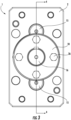
- the side surface 42 of the first end plate 2 may be a substantially planar surface having a central opening 48 for receiving the drive shaft 16, and first and second oppositely disposed openings 50 for receiving the arbor 15 therethrough.
- a first groove region 52 is disposed in the side surface 42 adjacent the central opening 48, while a pair of second groove regions 54 is disposed in the side surface adjacent the first and second openings 50.
- the first groove region 52 comprises first and second sets of spiral grooves 56A, B formed in the side surface 42 of the first end plate 2.
- Each of the first and second sets of spiral grooves 56A, B includes a plurality of individual spiral grooves 58 having first ends 58A positioned a first distance "D" from the central opening 48, and second ends 58B fanning out in a direction away from the central opening.
- the first and second sets of spiral grooves 56A, B may be disposed on opposite sides of the central opening 48 such that first and second non-grooved regions 60, 62 are formed adjacent the central opening 48. These non-grooved regions 60, 62 are positioned adjacent to the outlet ports "OP" of the first end plate 2. These non-grooved regions 60, 62 can be positioned to avoid creating a flow path between high and low pressure sides of the meshing gears.
- the second groove region 54 associated with each of the first and second openings 50 each includes a single set of spiral grooves 64 formed in the side surface 42 of the first end plate 2.
- the single set of spiral grooves 64 includes a plurality of individual spiral grooves 66 having first ends 66A positioned a first distance "D" from the respective first and second opening 50, and second ends 66B fanning out in a direction away from the opening.
- the single set of spiral grooves 64 may be arranged such that a non-grooved region 68 is formed adjacent each of the first and second openings.
- the non-grooved region 68 may be positioned adjacent to the outlet ports "OP" of the first end plate 2.
- the non-grooved region 68 can be positioned to avoid creating a flow path between high and low pressure sides of the meshing gears
- the spiral grooves 58, 66 may have the shape of a logarithmic curve, and are disposed in the surface of the end-plates 2, 4, 6 adjacent to the running faces 40 of the gears 12, 14.
- FIG. 6 which shows an exemplary view illustrating the disclosed spiral grooves 66 in the context of an exemplary gear 14, the second ends 66B of the spiral grooves 66 begin immediately beyond the root diameter "RD" of the gear and terminate at the first ends 66A at a diameter that is larger than the ID of the opening 50 in the end-plate 2 leaving a specified dam region 70 that runs the circumference of the opening.
- the rotation of the gear 14 in relation to the grooves 66 drives the fluid along the length of the groove 66 in the direction of arrow "A" (i.e., from the second end 66B to the first end 66A) until it reaches the dam region 70.
- This generates a low pressure zone in the grooves 66 at the gear root (adjacent the second ends 66B of the grooves 66) and a high pressure zone located at the termination (i.e., the first ends 66A) of the grooves 66.
- This high pressure causes an increase in the fluid film thickness between the gear 14 and end-plate 2, and imparts an axial force between the gear and end plate, eliminating contact.
- the grooves 66 are formed by a laser etching process, and have a uniform depth along their length. It will be appreciated that other techniques may be used to form the grooves. In addition, it is contemplated that in some instances the grooves may not be of uniform depth along their lengths.
- the groove-to-dam ratio is optimized for high load-carrying capacity or minimum take-off velocity (i.e., the speed at which separation between the gears and the end plate occurs).
- Groove depth may also be optimized for high load-carrying capacity.
- the grooves may have a depth of less than about 30 micrometers to optimize load carrying capacity and to minimize wear.
- the grooves may be used as wear indicators. That is, if the grooves begin to disappear such a condition can be observed during routine maintenance and/or cleaning.
- a width of the grooves adjacent to the root diameter "RD" of the associated gear 12, 14 does not exceed a width of the gear tooth at the root diameter. It will be appreciated that if the groove were wider than the gear tooth the groove could connect two fluid pockets, thus reducing the pressure differential between the volumes and adversely affecting the overall pressure building capability of the pump.
- r 1 is the radius at termination (i.e., at the first ends 58A, 66A of the grooves 58, 66) and ⁇ is the angle between the tangent line at any point on the log curve and the moving direction at that same point.
- the driving and driven gears 12, 14 of each of the first and second gear sets 36 will oppose groove sets on both sides of the gears, providing a self-centering feature for the gears which centering thrust is applied to either side of the gears.
- This equal and opposite thrust load can serve to center the gears between their associated end plates.
- the gear pump 100 includes a central gear plate 102, front and rear plates 104, 106, a seal plate 108 and a drive shaft 110.
- An inlet port (not shown) and an outlet port 112 may be formed in the central gear plate for moving fluid through the pump 100.
- the inlet and outlet ports may be coupled to inlet and outlet piping or tubing via an o-ring connection.
- the pump 1 may be fixed in its assembled form via a plurality of fasteners, which in the illustrated embodiment are socket head cap screws 114, 116.
- the drive shaft 110 includes a first gear 118 which intermeshes with a second gear 120 of a driven shaft 122.
- First and second asymmetrical bearings 124, 126 are positioned on opposite sides of the first and second gears 118, 120 and receive the drive shaft 110 and driven shaft 122 via respective bores 128A, B, 130A, B.
- the first and second gears 118, 120 and first and second asymmetrical bearings 124, 126 are received within an asymmetrical opening 132 in the central gear plate 102.
- the asymmetrical opening 132 is shaped to correspond to the shape of the asymmetrical bearings 124, 126, which facilitates installation of the bearings and maintains their alignment during operation.
- the seal plate 108 may fix a variety of sealing elements to the front plate 140 to prevent fluid leakage around the drive shaft 110.
- the sealing elements may include an o-ring 134, a lip seal 136 and a sealing sleeve 138, all of which may be received in a suitably configured recess 140 in the front plate 104.
- FIG. 8 shows the second asymmetrical bearing 126.
- the side surface 142 of the second asymmetrical bearing 126 may have a substantially planar surface with bores 130A and 130B.
- the side surface 142 will face the drive gear 118 and the driven gear 120 when the pump 100 is assembled.
- Groove regions 154 are disposed in the side surface 142 adjacent the bores 130A, 130B.
- the groove regions 154 each include a set of spiral grooves 164 formed in the side surface 142 of the second asymmetrical bearing 126.
- the set of spiral grooves 164 includes a plurality of individual spiral grooves 166 having first ends 166A positioned a first distance "D" from the respective bores 130A, 130B, and second ends 166B fanning out in a direction away from the bores.
- the set of spiral grooves 164 may be arranged such that a non-grooved region 168 is formed adjacent each of the bores.
- the non-grooved region 168 may be positioned to avoid creating a flow path between high and low pressure sides of the meshing gears 118, 122.
- the spiral grooves 166 may have the shape of a logarithmic curve, and are disposed in the surface of the asymmetrical bearings 124, 126 adjacent to the running faces of the gears 118, 120.
- the grooves and groove arrangement of the embodiment of FIGS. 7 and 8 can have any or all of the physical and/or operational features previously described in relation to the grooves of the embodiment of FIGS. 5 and 6 .
- spiral grooves can be provided on the side faces 40 of the drive and/or driven gears 12, 14 in lieu of the first, second and third end plates 2, 4, 6 or the first and second asymmetrical bearings 124, 126.
- Such spiral grooves can have some or all of the features previously described in relation to FIGS. 5 and 6 .
- the disclosed arrangement can be applied to only one plate in order to generate a counteracting axial force.
- the disclosed arrangement can be incorporated into pumps that will have applications with high rates of gear face galling or low lubricity applications that impart high wear on the gear faces. This disclosed arrangement can also be utilized in low viscosity applications, making use of the side clearance equalization to reduce side clearance slip and therefore improve overall efficiency. The disclosed arrangement can also be used in applications having start-up face failure issues.
- This disclosed spiral groove arrangement can be installed after all other manufacturing processes are completed, thus enabling better control of groove location and depth.
- this precise and symmetric spiral groove feature positioned adjacent to opposed gear face can create a desirable centering balance of forces.
- the presence of the disclosed fluid dam can ensure minimal negative impact on pumping efficiency.
- the disclosed arrangement can generate separation force in addition to acting as a fluid reservoir.
- the extension of the spiral groove feature beyond the root diameter of the gear can allow for more efficient filling of the groove and better pressure generation.
- the thrust load can cause the gear to run with more equal side clearances.
- the disclosed arrangement thus eliminates the need for exotic materials, coatings, or surface treatments to prevent wear.
- the disclosed arrangement provides a less costly manufacturing solution, and is also more easily controlled as compared to pre-heat treatment processes or hard ground features as have been used previously.
- the disclosed arrangement can also improve pump efficiency, due to equalized side clearances between the gear side faces and the associated end plates. Equalized side clearances can also reduce asymmetrical wear of the pump end plates or bearing surfaces.
- the inward-pumping action caused by the spiral grooves can generate higher load-bearing capability as compared to other thrust generating designs such as sliding bearings.
Landscapes
- Engineering & Computer Science (AREA)
- General Engineering & Computer Science (AREA)
- Mechanical Engineering (AREA)
- Physics & Mathematics (AREA)
- Fluid Mechanics (AREA)
- Chemical & Material Sciences (AREA)
- Oil, Petroleum & Natural Gas (AREA)
- Rotary Pumps (AREA)
Description
- The disclosure generally relates to bearings for use in pump assemblies, and more particularly to gear pumps having end plates or bearings with spiral grooves formed therein.
- Gear pumps have been employed in a variety of industries and environments. In general, gear pumps include a housing with one or more plates that hold a set of intermeshing gears. As the gears turn, fluid moves between the gear teeth and the housing and is discharged from the pump due to the intermeshing of the gears. The gears are attached to shafts that run axially from the gear faces, and these shafts run on one or more bearing surfaces.
- Lubrication of bearing surfaces in gear pumps is often provided by the fluid being conveyed through the pump. One problem with such an arrangement is that upon startup, an adequate lubricating film may not be present (or may not be immediately generated) and thus some bearing surfaces can be subject to wear resulting in damage or premature failure. For example, where an inadequate lubricating film exists between the side faces of the gears and the adjacent end plates, wear related damage to the gears and/or end plates can occur. This problem has previously been addressed by employing hydrodynamic slide bearings with variable depth, and/or through the use of gall-resistant materials aimed at withstanding harsh contact. Surface treatments or coatings of other wear resistant materials have also been applied to the plate surface to resist galling.
- Problems with these approaches include difficulty in generating adequate thrust (using the aforementioned slide bearings) without adversely affecting the pumps overall efficiency. In addition, under adverse pumping conditions, gall-resistant materials are still subject to premature failure.
-
JPS61104178A GB883356A US4402653A discloses a vane pump with pressure generating spiral grooves in a lateral wall of a housing. - Thus, there is a need for an improved design for reducing wear in gear pumps, particularly in gear and endplate bearing surfaces.
- A gear pump is disclosed. A gear pump according to the invention is defined in independent claim 1.
- An end plate is disclosed for use in a gear pump. The end plate can include a central opening and a first opening for receiving shafts associated with first and second gears of the gear pump. A plurality of spiral grooves can be formed in a side surface of the end plate. The plurality of spiral grooves can include a first groove region positioned adjacent the central opening and a second groove region positioned adjacent the first opening.
- An alternative gear pump according to the invention is defined in independent claim 5.
- By way of example, a specific embodiment of the disclosed device will now be described, with reference to the accompanying drawings:
-
FIG. 1 is a perspective view of a pump including the disclosed spiral grooves in a plurality of end plates; -
FIG. 2 is an exploded view of the pump ofFIG. 1 ; -
FIG. 3 is an end view of the pump ofFIG. 1 ; -
FIG. 4 is a cross-section view of the pump ofFIG. 1 , taken along line 4-4 ofFIG. 3 ; -
FIG. 5 is a side view of an exemplary end plate for use in the pump ofFIG. 1 ; -
FIG. 6 is a schematic view of the position of the spiral grooves of the end plate ofFIG. 5 adjacent an exemplary gear of the pump ofFIG. 1 ; -
FIG. 7 is an exploded view of a pump including the disclosed spiral grooves in first and second bearings; and -
FIG. 8 is a side view of an exemplary bearing for use in the pump ofFIG. 7 . - A gear pump is disclosed having features configured to reduce wear of bearing surfaces during pump startup and to provide efficient performance in operation. In one embodiment, spiral grooves are provided in the end-plates adjacent to the faces of the pump gears. These grooves are oriented in an inward-pumping orientation in order to generate a high pressure zone between the opposing faces and ensure separation between the gear and plate.
-
FIGS. 1-3 show an exemplary gear pump 1 having first, second andthird end plates second gear plates intermeshing gears drive shaft 16. The gear pump 1 also includes apacking assembly 18 including apacking housing 20, a plurality ofpacking rings 22, apacking gland 24, a plurality offasteners 26 and a thrust washer 28 seals against thefirst end plate 2 to prevent fluid leakage past thedrive shaft 16. A key 30 may be set into thedrive shaft 16 to couple the drive shaft to a motor (not shown). Thedrive shaft 16 may be coupled to thedrive gears 12, while the drivengears 14 may be coupled to associatedarbors 15 which themselves are rotatably supported inopenings 17 in thefirst end plate 2. Thedrive gears 12 and drivengears 14 may be received withinopenings 19 in the first andsecond gear plates - Inlet and outlet ports (not shown) may be formed in one or more of the
end plates third end plates second gear plates dowels 32 positioned in associated openings in the respective plates, and the plates may be fixed in its assembled form via a plurality offasteners 34, which in the illustrated embodiment are socket head cap screws. -
FIG. 2 shows the pump 1 in exploded form. As can be seen, thedrive shaft 16 couples to first andsecond driving gears 12, which in the illustrated embodiment are the center gears of two three-gear stages second driving gears 12 intermesh with respective second and third drivengears 14 to power each of the three-gear stages.FIG. 3 is an end view of the pump 1 showing thedrive shaft 16,packing assembly 18 andend plate 2. -
FIG. 4 shows the internal inter-relation of components of the pump 1 when assembled. As can be seen, the first andthird end plates second gear plates second end plate 4 therebetween, along with the driving and drivengears gear stages - As can be seen, the
drive gears 12 and drivengears 14 are positioned directly adjacent to the first, second andthird end plates drive gears 12 and the drivengears 14 can contactopposing side surfaces opposing side surfaces - Referring to
FIG. 5 , thefirst end plate 2 is shown. Although this description will proceed with relation to thefirst end plate 2 it will be appreciated that the description will apply equally to the second andthird end plates side surface 42 of thefirst end plate 2 may be a substantially planar surface having acentral opening 48 for receiving thedrive shaft 16, and first and second oppositely disposedopenings 50 for receiving thearbor 15 therethrough. Afirst groove region 52 is disposed in theside surface 42 adjacent thecentral opening 48, while a pair ofsecond groove regions 54 is disposed in the side surface adjacent the first andsecond openings 50. - The
first groove region 52 comprises first and second sets ofspiral grooves 56A, B formed in theside surface 42 of thefirst end plate 2. Each of the first and second sets ofspiral grooves 56A, B includes a plurality of individualspiral grooves 58 havingfirst ends 58A positioned a first distance "D" from thecentral opening 48, andsecond ends 58B fanning out in a direction away from the central opening. The first and second sets ofspiral grooves 56A, B may be disposed on opposite sides of thecentral opening 48 such that first and second non-groovedregions central opening 48. Thesenon-grooved regions first end plate 2. Thesenon-grooved regions - The
second groove region 54 associated with each of the first andsecond openings 50 each includes a single set ofspiral grooves 64 formed in theside surface 42 of thefirst end plate 2. The single set ofspiral grooves 64 includes a plurality ofindividual spiral grooves 66 having first ends 66A positioned a first distance "D" from the respective first andsecond opening 50, and second ends 66B fanning out in a direction away from the opening. The single set ofspiral grooves 64 may be arranged such that anon-grooved region 68 is formed adjacent each of the first and second openings. Thenon-grooved region 68 may be positioned adjacent to the outlet ports "OP" of thefirst end plate 2. Thenon-grooved region 68 can be positioned to avoid creating a flow path between high and low pressure sides of the meshing gears - In some embodiments the
spiral grooves plates gears FIG. 6 , which shows an exemplary view illustrating the disclosedspiral grooves 66 in the context of anexemplary gear 14, the second ends 66B of thespiral grooves 66 begin immediately beyond the root diameter "RD" of the gear and terminate at the first ends 66A at a diameter that is larger than the ID of theopening 50 in the end-plate 2 leaving a specifieddam region 70 that runs the circumference of the opening. The rotation of thegear 14 in relation to thegrooves 66 drives the fluid along the length of thegroove 66 in the direction of arrow "A" (i.e., from thesecond end 66B to thefirst end 66A) until it reaches thedam region 70. This generates a low pressure zone in thegrooves 66 at the gear root (adjacent the second ends 66B of the grooves 66) and a high pressure zone located at the termination (i.e., the first ends 66A) of thegrooves 66. This high pressure causes an increase in the fluid film thickness between thegear 14 and end-plate 2, and imparts an axial force between the gear and end plate, eliminating contact. - In some embodiments the
grooves 66 are formed by a laser etching process, and have a uniform depth along their length. It will be appreciated that other techniques may be used to form the grooves. In addition, it is contemplated that in some instances the grooves may not be of uniform depth along their lengths. - In some embodiments, the groove-to-dam ratio is optimized for high load-carrying capacity or minimum take-off velocity (i.e., the speed at which separation between the gears and the end plate occurs). Groove depth may also be optimized for high load-carrying capacity. The grooves may have a depth of less than about 30 micrometers to optimize load carrying capacity and to minimize wear. In addition, if kept shallow the grooves may be used as wear indicators. That is, if the grooves begin to disappear such a condition can be observed during routine maintenance and/or cleaning.
- According to the invention a width of the grooves adjacent to the root diameter "RD" of the associated
gear - In some embodiments groove spiral shape may be obtained using the formula:

- Where r and ϕ are polar coordinates, r1 is the radius at termination (i.e., at the first ends 58A, 66A of the
grooves 58, 66) and α is the angle between the tangent line at any point on the log curve and the moving direction at that same point. - As previously noted, although a single set of
grooves 66 have been described in relation to thefirst end plate 2, it will be appreciated that the same description equally applies to the remaining groove sets and the second andthird end plates second end plate 4 will have groove sets on both sides of the end plate to interact with the first and second gear sets 36, 38. - As such, the driving and driven
gears - Referring now to
FIGS. 7 and8 , analternative gear pump 100 is shown. Thegear pump 100 includes a central gear plate 102, front andrear plates seal plate 108 and adrive shaft 110. An inlet port (not shown) and anoutlet port 112 may be formed in the central gear plate for moving fluid through thepump 100. The inlet and outlet ports may be coupled to inlet and outlet piping or tubing via an o-ring connection. The pump 1 may be fixed in its assembled form via a plurality of fasteners, which in the illustrated embodiment are socket head cap screws 114, 116. - The
drive shaft 110 includes afirst gear 118 which intermeshes with asecond gear 120 of a drivenshaft 122. First and secondasymmetrical bearings second gears drive shaft 110 and drivenshaft 122 viarespective bores 128A, B, 130A, B. The first andsecond gears asymmetrical bearings asymmetrical opening 132 in the central gear plate 102. In the illustrated embodiment, theasymmetrical opening 132 is shaped to correspond to the shape of theasymmetrical bearings - The
seal plate 108 may fix a variety of sealing elements to thefront plate 140 to prevent fluid leakage around thedrive shaft 110. The sealing elements may include an o-ring 134, alip seal 136 and a sealingsleeve 138, all of which may be received in a suitably configuredrecess 140 in thefront plate 104. -
FIG. 8 shows the secondasymmetrical bearing 126. Although this description will proceed with relation to the secondasymmetrical bearing 126 it will be appreciated that the description equally applies to the firstasymmetrical bearing 124. Theside surface 142 of the secondasymmetrical bearing 126 may have a substantially planar surface withbores side surface 142 will face thedrive gear 118 and the drivengear 120 when thepump 100 is assembled.Groove regions 154 are disposed in theside surface 142 adjacent thebores groove regions 154 each include a set ofspiral grooves 164 formed in theside surface 142 of the secondasymmetrical bearing 126. The set ofspiral grooves 164 includes a plurality ofindividual spiral grooves 166 having first ends 166A positioned a first distance "D" from therespective bores spiral grooves 164 may be arranged such that anon-grooved region 168 is formed adjacent each of the bores. Thenon-grooved region 168 may be positioned to avoid creating a flow path between high and low pressure sides of the meshing gears 118, 122. - In some embodiments the
spiral grooves 166 may have the shape of a logarithmic curve, and are disposed in the surface of theasymmetrical bearings gears FIGS. 7 and8 can have any or all of the physical and/or operational features previously described in relation to the grooves of the embodiment ofFIGS. 5 and6 . - In some embodiments not within the scope of the claims the spiral grooves can be provided on the side faces 40 of the drive and/or driven
gears third end plates asymmetrical bearings FIGS. 5 and6 . - In pumps that are subject to significant axial load in one direction, the disclosed arrangement can be applied to only one plate in order to generate a counteracting axial force.
- The disclosed arrangement can be incorporated into pumps that will have applications with high rates of gear face galling or low lubricity applications that impart high wear on the gear faces. This disclosed arrangement can also be utilized in low viscosity applications, making use of the side clearance equalization to reduce side clearance slip and therefore improve overall efficiency. The disclosed arrangement can also be used in applications having start-up face failure issues.
- This disclosed spiral groove arrangement can be installed after all other manufacturing processes are completed, thus enabling better control of groove location and depth. As noted, this precise and symmetric spiral groove feature positioned adjacent to opposed gear face can create a desirable centering balance of forces. The presence of the disclosed fluid dam can ensure minimal negative impact on pumping efficiency. The disclosed arrangement can generate separation force in addition to acting as a fluid reservoir. The extension of the spiral groove feature beyond the root diameter of the gear can allow for more efficient filling of the groove and better pressure generation. At a threshold speed, the thrust load can cause the gear to run with more equal side clearances. The disclosed arrangement thus eliminates the need for exotic materials, coatings, or surface treatments to prevent wear.
- The disclosed arrangement provides a less costly manufacturing solution, and is also more easily controlled as compared to pre-heat treatment processes or hard ground features as have been used previously. The disclosed arrangement can also improve pump efficiency, due to equalized side clearances between the gear side faces and the associated end plates. Equalized side clearances can also reduce asymmetrical wear of the pump end plates or bearing surfaces. The inward-pumping action caused by the spiral grooves can generate higher load-bearing capability as compared to other thrust generating designs such as sliding bearings.
- Based on the foregoing information, it will be readily understood by those persons skilled in the art that the disclosed arrangement is susceptible of broad utility and application. Many embodiments and adaptations of the disclosed arrangement other than those specifically described herein will be apparent from or reasonably suggested by the disclosed arrangement and the foregoing descriptions thereof. Accordingly, while the disclosed arrangement has been described herein in detail in relation to its preferred embodiment, it is to be understood that this disclosure is only illustrative and exemplary and is made merely for the purpose of providing a full and enabling disclosure. The foregoing disclosure is not intended to be construed to limit or otherwise exclude any such other embodiments, adaptations, variations, modifications or equivalent arrangements; the invention being limited only by the claims appended hereto. Although specific terms are employed herein, they are used in a generic and descriptive sense only and not for the purpose of limitation.
Claims (8)
- A gear pump (1), comprising:a housing (20);a drive gear (12) and a driven gear (14), the drive gear (12) and the driven gear (14) each having gear side surfaces (40); andfirst and second end plates (2,4,6) having plate side surfaces (42,44,46), the plate side surfaces each including a plurality of spiral grooves (58,66) disposed opposite the gear side surfaces;the first and second end plates further comprising:
a first opening (48) and a second opening (50) for receiving shafts (15,16) associated with the drive gear (12) and the driven gear (14); andwherein the plurality of spiral grooves includes a first groove region (56A,56B) positioned adjacent the first opening (48) and a second groove region (66A) positioned adjacent the second opening (50);wherein the plurality of spiral grooves are oriented such that rotation of the drive gear (12) and the driven gear (14) generates a low pressure zone in the plurality of spiral grooves adjacent a gear root of the drive gear and a gear root of the driven gear and generates a high pressure zone in the plurality of spiral grooves adjacent the first opening (48) and the second opening (50); andwherein the plurality of spiral grooves of the first groove region (56A, 56B) have first ends positioned a first distance from the first opening (48), thereby forming a circumferential dam around the first opening; and wherein the plurality of spiral grooves of the second groove region (66A) have first ends positioned a first distance from the second opening (50), thereby forming a circumferential dam around the second opening; andwherein the width of the plurality of spiral grooves adjacent a root diameter (RD) of the gear teeth of the drive gear (12) and driven gear (14) does not extend beyond a width of the gear teeth of the drive gear (12) and the driven gear (14) at the root diameter (RD) of the gear teeth. - The gear pump (1) of claim 1, wherein a drive shaft (16) is receivable in the first opening, and an arbor (15) is receivable in the second opening, the drive gear (12) coupled to the drive shaft and the driven gear engaged with the drive gear to rotate the driven gear about the arbor (15).
- The gear pump (1) of claim 1 or 2, further comprising a drive shaft (16) and two arbors (15), wherein each of the end plates (2,4,6) has a first opening (48) arranged centrally in the end plate, a second and third oppositely disposed opening (50) for receiving the arbors (15) therethrough, and a first and second outlet port (OP) for moving fluid through the gear pump (1), wherein the first groove region (56A,56B) includes first and second sets of spiral grooves, each of the first and second sets of spiral grooves including a plurality of individual spiral grooves (58), the first and second sets of spiral grooves disposed on opposite sides of the first opening (48) such that first and second non-grooved regions (60,62) are formed adjacent the first opening (48), the first and second non-grooved regions being positioned adjacent to first and second outlet ports (OP) of the first end plate (2), the first and second non-grooved regions positioned to prevent a flow path between high and low pressure sides of the drive gear (12) and the driven gear (14).
- The gear pump (1) of any of the preceding claims, wherein the plurality of spiral grooves have a shape of a logarithmic curve.
- A gear pump (100), comprising:a housing (20);a drive gear (118) and a driven gear (120), the drive gear and the driven gear each having gear side surfaces; andfirst and second bearings (124,126) respectively arranged in a first end plate (104) and a second end plate (106)s, having bearing side surfaces (142), the bearing side surfaces each including a plurality of spiral grooves (164,166) disposed opposite the gear side surfaces;the first and second bearings comprising:
a first opening (128A; 130A) and a second opening (128B; 130B) for receiving shafts associated with the drive gear (118) and the driven gear (120); andwherein the plurality of spiral grooves includes a first groove region positioned adjacent the first opening and a second groove region positioned adjacent the second opening;wherein the plurality of spiral grooves are oriented such that rotation of the drive gear (12) and the driven gear (14) generates a low pressure zone in the plurality of spiral grooves adjacent a gear root of the drive gear and a gear root of the driven gear and generates a high pressure zone in the plurality of spiral grooves adjacent the first opening and the second opening;wherein the plurality of spiral grooves of the first groove region have first ends positioned a first distance from the central opening, thereby forming a circumferential dam around the first opening; and wherein the plurality of spiral grooves of the second groove region have first ends positioned a first distance from the second opening, thereby forming a circumferential dam around the second opening; andwherein the width of the plurality of spiral grooves adjacent a root diameter (RD) of the gear teeth of the drive gear and the driven gear does not extend beyond a width of the gear teeth of the drive gear and the driven gear at a root diameter (RD) of the gear teeth. - The pump (100) of claim 5, wherein a drive shaft (110) is receivable in the first opening, and an arbor (122) is receivable in the second opening, the drive gear coupled to the drive shaft and the driven gear engaged with the drive gear to rotate the driven gear about the arbor.
- The gear pump of claim 6, further comprising a driven shaft (122), wherein each of the bearings (124;126) has a first opening (128A;130A) arranged in the bearing for receiving the drive shaft (110) and a second opening (128B;130B) arranged in the bearing for receiving the driven shaft (122), the first groove region including first and second sets of spiral grooves, each of the first and second sets of spiral grooves including a plurality of individual spiral grooves, the first and second sets of spiral grooves disposed on opposite sides of the first opening (128A; 130A) such that first and second non-grooved regions (168) are formed adjacent the first opening, the first and second non-grooved regions positioned adjacent to first and second outlet ports of the first end plate (104), the first and second non-grooved regions positioned to prevent a flow path between high- and low-pressure sides of the drive gear and the driven gear.
- The pump of any of claims 5-7, wherein the plurality of spiral grooves have a shape of a logarithmic curve.
Applications Claiming Priority (2)
| Application Number | Priority Date | Filing Date | Title |
|---|---|---|---|
| US201461968568P | 2014-03-21 | 2014-03-21 | |
| PCT/US2015/021444 WO2015143141A1 (en) | 2014-03-21 | 2015-03-19 | Gear pump with end plates or bearings having spiral grooves |
Publications (4)
| Publication Number | Publication Date |
|---|---|
| EP3120027A1 EP3120027A1 (en) | 2017-01-25 |
| EP3120027A4 EP3120027A4 (en) | 2017-12-06 |
| EP3120027B1 true EP3120027B1 (en) | 2024-11-06 |
| EP3120027C0 EP3120027C0 (en) | 2024-11-06 |
Family
ID=54145309
Family Applications (1)
| Application Number | Title | Priority Date | Filing Date |
|---|---|---|---|
| EP15765696.8A Active EP3120027B1 (en) | 2014-03-21 | 2015-03-19 | Gear pump with end plates or bearings having spiral grooves |
Country Status (3)
| Country | Link |
|---|---|
| US (1) | US10323636B2 (en) |
| EP (1) | EP3120027B1 (en) |
| WO (1) | WO2015143141A1 (en) |
Families Citing this family (11)
| Publication number | Priority date | Publication date | Assignee | Title |
|---|---|---|---|---|
| US20200025199A1 (en) * | 2018-07-17 | 2020-01-23 | Air Squared, Inc. | Dual drive co-rotating spinning scroll compressor or expander |
| US11473572B2 (en) | 2019-06-25 | 2022-10-18 | Air Squared, Inc. | Aftercooler for cooling compressed working fluid |
| IT202000013588A1 (en) * | 2020-06-08 | 2021-12-08 | Bosch Gmbh Robert | PUMPING UNIT TO FEED FUEL, PREFERABLY DIESEL, TO AN INTERNAL COMBUSTION ENGINE |
| US11624360B2 (en) | 2020-12-23 | 2023-04-11 | Hamilton Sundstrand Corporation | Gear pump with gear including etched surfaces |
| WO2022187920A1 (en) * | 2021-03-07 | 2022-09-15 | Oliveira Luciano Barros | Pumping system with inner scrolls |
| US11662026B2 (en) | 2021-08-16 | 2023-05-30 | Hamilton Sandstrand Corporation | Seal with surface indents |
| US11713716B2 (en) * | 2021-08-16 | 2023-08-01 | Hamilton Sundstrand Corporation | Gear and bearing indents to induce fluid film |
| CN114215742A (en) * | 2021-11-10 | 2022-03-22 | 浙江环誉泵业科技有限公司 | A low leakage dynamic pressure fluid sealing end face structure with self-circulation and backflow function |
| CN114320880B (en) * | 2021-11-10 | 2024-06-11 | 浙江环誉泵业科技有限公司 | Gear with self-lubricating and self-cooling functions |
| CN115773239B (en) * | 2022-11-22 | 2023-12-26 | 江苏威博液压股份有限公司 | Four-quadrant internal gear pump |
| DE102023105779A1 (en) * | 2023-03-08 | 2024-09-12 | Valeo Embrayages | Gear pump |
Family Cites Families (11)
| Publication number | Priority date | Publication date | Assignee | Title |
|---|---|---|---|---|
| US1486837A (en) * | 1923-05-01 | 1924-03-11 | Hill Compressor & Pump Company | Rotary pump |
| GB883356A (en) | 1959-04-24 | 1961-11-29 | Thompson Ramo Wooldridge Inc | Improvements in or relating to pumps |
| JPS56106088A (en) | 1980-01-29 | 1981-08-24 | Matsushita Electric Ind Co Ltd | Rotary type fluid equipment |
| JPS61104178A (en) | 1984-10-29 | 1986-05-22 | Taiho Kogyo Co Ltd | rotary oil pump device |
| JPH09280181A (en) | 1996-04-09 | 1997-10-28 | Shimadzu Corp | Gear pump |
| DE19744466C2 (en) | 1997-10-08 | 1999-08-19 | Kt Kirsten Technologie Entwick | Screw compressor |
| US6171089B1 (en) * | 1998-05-12 | 2001-01-09 | Parker-Hannifin Corporation | External gear pump with drive gear seal |
| WO2006015218A1 (en) * | 2004-07-30 | 2006-02-09 | Pulsafeeder, Inc. | Non-metallic gear pump with magnetic coupling assembly |
| JP2011052644A (en) | 2009-09-03 | 2011-03-17 | Toyota Motor Corp | Oil pump for vehicle |
| JP2013172569A (en) * | 2012-02-21 | 2013-09-02 | Samsung Electromechanics Japan Advanced Technology Co Ltd | Rotary apparatus |
| US8998496B2 (en) * | 2012-03-30 | 2015-04-07 | Imo Industries, Inc. | Gear pump with asymmetrical dual bearing |
-
2015
- 2015-03-19 EP EP15765696.8A patent/EP3120027B1/en active Active
- 2015-03-19 US US15/127,584 patent/US10323636B2/en active Active
- 2015-03-19 WO PCT/US2015/021444 patent/WO2015143141A1/en not_active Ceased
Also Published As
| Publication number | Publication date |
|---|---|
| US10323636B2 (en) | 2019-06-18 |
| WO2015143141A1 (en) | 2015-09-24 |
| EP3120027A1 (en) | 2017-01-25 |
| US20170175736A1 (en) | 2017-06-22 |
| EP3120027A4 (en) | 2017-12-06 |
| EP3120027C0 (en) | 2024-11-06 |
Similar Documents
| Publication | Publication Date | Title |
|---|---|---|
| US10323636B2 (en) | Gear pump with end plates or bearings having spiral grooves | |
| US1795579A (en) | Rotary pump | |
| EP1540184B1 (en) | Gear pump | |
| US2479077A (en) | Balanced hydraulic pump or motor | |
| EP2940353B1 (en) | Sliding component | |
| US4470776A (en) | Methods and apparatus for gear pump lubrication | |
| CN103267132A (en) | Self-pumping fluid-dynamic-pressure-type mechanical seal | |
| JP5465366B1 (en) | Hydraulic device | |
| GB2138074A (en) | A hydraulic pump | |
| CN105179233B (en) | Suitable for the vane pump of injection machine | |
| US8651843B2 (en) | High efficiency fixed displacement vane pump | |
| CN110617213B (en) | Spiral tooth double-arc tooth-shaped hydraulic gear pump with dynamic and static pressure floating support at shaft end | |
| CN100476210C (en) | Internal gear pump or motor | |
| EP3449129B1 (en) | Modular thrust-compensating rotor assembly | |
| JP6639505B2 (en) | Gerotor pump | |
| CN106555752A (en) | A L-type external gear rotary pump suitable for ultra-low viscosity medium | |
| CN112065722A (en) | Claw type pump rotor end face sealing structure and claw type pump | |
| JP5361074B2 (en) | Helical gear pump | |
| US9951619B2 (en) | Actuator of a rotary positive displacement machine | |
| JP2017537265A5 (en) | ||
| CN210919828U (en) | Bearing for fluid pump | |
| CN205117717U (en) | Impeller pump suitable for machinery of moulding plastics | |
| CN103603802B (en) | A kind of external gear rotary pump with biased teeth wheel set | |
| CN110425221B (en) | A bearing for a fluid pump | |
| US20210372399A1 (en) | High pressure pump |
Legal Events
| Date | Code | Title | Description |
|---|---|---|---|
| STAA | Information on the status of an ep patent application or granted ep patent |
Free format text: STATUS: THE INTERNATIONAL PUBLICATION HAS BEEN MADE |
|
| PUAI | Public reference made under article 153(3) epc to a published international application that has entered the european phase |
Free format text: ORIGINAL CODE: 0009012 |
|
| STAA | Information on the status of an ep patent application or granted ep patent |
Free format text: STATUS: REQUEST FOR EXAMINATION WAS MADE |
|
| 17P | Request for examination filed |
Effective date: 20160914 |
|
| AK | Designated contracting states |
Kind code of ref document: A1 Designated state(s): AL AT BE BG CH CY CZ DE DK EE ES FI FR GB GR HR HU IE IS IT LI LT LU LV MC MK MT NL NO PL PT RO RS SE SI SK SM TR |
|
| AX | Request for extension of the european patent |
Extension state: BA ME |
|
| DAV | Request for validation of the european patent (deleted) | ||
| DAX | Request for extension of the european patent (deleted) | ||
| RIC1 | Information provided on ipc code assigned before grant |
Ipc: F04C 2/08 20060101ALI20171026BHEP Ipc: F04C 15/00 20060101ALI20171026BHEP Ipc: F01C 21/10 20060101ALI20171026BHEP Ipc: F04C 29/00 20060101ALI20171026BHEP Ipc: F04C 18/14 20060101ALI20171026BHEP Ipc: F04C 13/00 20060101AFI20171026BHEP Ipc: F04C 2/14 20060101ALI20171026BHEP Ipc: F04C 2/18 20060101ALI20171026BHEP Ipc: F16C 17/10 20060101ALI20171026BHEP |
|
| A4 | Supplementary search report drawn up and despatched |
Effective date: 20171107 |
|
| RAP1 | Party data changed (applicant data changed or rights of an application transferred) |
Owner name: CIRCOR PUMPS NORTH AMERICA, LLC |
|
| STAA | Information on the status of an ep patent application or granted ep patent |
Free format text: STATUS: EXAMINATION IS IN PROGRESS |
|
| 17Q | First examination report despatched |
Effective date: 20200512 |
|
| GRAP | Despatch of communication of intention to grant a patent |
Free format text: ORIGINAL CODE: EPIDOSNIGR1 |
|
| STAA | Information on the status of an ep patent application or granted ep patent |
Free format text: STATUS: GRANT OF PATENT IS INTENDED |
|
| INTG | Intention to grant announced |
Effective date: 20240605 |
|
| GRAS | Grant fee paid |
Free format text: ORIGINAL CODE: EPIDOSNIGR3 |
|
| GRAA | (expected) grant |
Free format text: ORIGINAL CODE: 0009210 |
|
| STAA | Information on the status of an ep patent application or granted ep patent |
Free format text: STATUS: THE PATENT HAS BEEN GRANTED |
|
| AK | Designated contracting states |
Kind code of ref document: B1 Designated state(s): AL AT BE BG CH CY CZ DE DK EE ES FI FR GB GR HR HU IE IS IT LI LT LU LV MC MK MT NL NO PL PT RO RS SE SI SK SM TR |
|
| REG | Reference to a national code |
Ref country code: GB Ref legal event code: FG4D |
|
| REG | Reference to a national code |
Ref country code: CH Ref legal event code: EP |
|
| REG | Reference to a national code |
Ref country code: DE Ref legal event code: R096 Ref document number: 602015090323 Country of ref document: DE |
|
| REG | Reference to a national code |
Ref country code: IE Ref legal event code: FG4D |
|
| U01 | Request for unitary effect filed |
Effective date: 20241121 |
|
| U07 | Unitary effect registered |
Designated state(s): AT BE BG DE DK EE FI FR IT LT LU LV MT NL PT RO SE SI Effective date: 20241128 |
|
| U20 | Renewal fee for the european patent with unitary effect paid |
Year of fee payment: 11 Effective date: 20250205 |
|
| PG25 | Lapsed in a contracting state [announced via postgrant information from national office to epo] |
Ref country code: HR Free format text: LAPSE BECAUSE OF FAILURE TO SUBMIT A TRANSLATION OF THE DESCRIPTION OR TO PAY THE FEE WITHIN THE PRESCRIBED TIME-LIMIT Effective date: 20241106 Ref country code: IS Free format text: LAPSE BECAUSE OF FAILURE TO SUBMIT A TRANSLATION OF THE DESCRIPTION OR TO PAY THE FEE WITHIN THE PRESCRIBED TIME-LIMIT Effective date: 20250306 |
|
| PG25 | Lapsed in a contracting state [announced via postgrant information from national office to epo] |
Ref country code: ES Free format text: LAPSE BECAUSE OF FAILURE TO SUBMIT A TRANSLATION OF THE DESCRIPTION OR TO PAY THE FEE WITHIN THE PRESCRIBED TIME-LIMIT Effective date: 20241106 |
|
| PG25 | Lapsed in a contracting state [announced via postgrant information from national office to epo] |
Ref country code: NO Free format text: LAPSE BECAUSE OF FAILURE TO SUBMIT A TRANSLATION OF THE DESCRIPTION OR TO PAY THE FEE WITHIN THE PRESCRIBED TIME-LIMIT Effective date: 20250206 |
|
| PG25 | Lapsed in a contracting state [announced via postgrant information from national office to epo] |
Ref country code: GR Free format text: LAPSE BECAUSE OF FAILURE TO SUBMIT A TRANSLATION OF THE DESCRIPTION OR TO PAY THE FEE WITHIN THE PRESCRIBED TIME-LIMIT Effective date: 20250207 |
|
| PG25 | Lapsed in a contracting state [announced via postgrant information from national office to epo] |
Ref country code: PL Free format text: LAPSE BECAUSE OF FAILURE TO SUBMIT A TRANSLATION OF THE DESCRIPTION OR TO PAY THE FEE WITHIN THE PRESCRIBED TIME-LIMIT Effective date: 20241106 |
|
| PG25 | Lapsed in a contracting state [announced via postgrant information from national office to epo] |
Ref country code: RS Free format text: LAPSE BECAUSE OF FAILURE TO SUBMIT A TRANSLATION OF THE DESCRIPTION OR TO PAY THE FEE WITHIN THE PRESCRIBED TIME-LIMIT Effective date: 20250206 |
|
| PG25 | Lapsed in a contracting state [announced via postgrant information from national office to epo] |
Ref country code: SM Free format text: LAPSE BECAUSE OF FAILURE TO SUBMIT A TRANSLATION OF THE DESCRIPTION OR TO PAY THE FEE WITHIN THE PRESCRIBED TIME-LIMIT Effective date: 20241106 |
|
| PG25 | Lapsed in a contracting state [announced via postgrant information from national office to epo] |
Ref country code: SK Free format text: LAPSE BECAUSE OF FAILURE TO SUBMIT A TRANSLATION OF THE DESCRIPTION OR TO PAY THE FEE WITHIN THE PRESCRIBED TIME-LIMIT Effective date: 20241106 |
|
| PG25 | Lapsed in a contracting state [announced via postgrant information from national office to epo] |
Ref country code: CZ Free format text: LAPSE BECAUSE OF FAILURE TO SUBMIT A TRANSLATION OF THE DESCRIPTION OR TO PAY THE FEE WITHIN THE PRESCRIBED TIME-LIMIT Effective date: 20241106 |
|
| PLBE | No opposition filed within time limit |
Free format text: ORIGINAL CODE: 0009261 |
|
| STAA | Information on the status of an ep patent application or granted ep patent |
Free format text: STATUS: NO OPPOSITION FILED WITHIN TIME LIMIT |
|
| PG25 | Lapsed in a contracting state [announced via postgrant information from national office to epo] |
Ref country code: MC Free format text: LAPSE BECAUSE OF FAILURE TO SUBMIT A TRANSLATION OF THE DESCRIPTION OR TO PAY THE FEE WITHIN THE PRESCRIBED TIME-LIMIT Effective date: 20241106 |
|
| 26N | No opposition filed |
Effective date: 20250807 |
|
| REG | Reference to a national code |
Ref country code: CH Ref legal event code: H13 Free format text: ST27 STATUS EVENT CODE: U-0-0-H10-H13 (AS PROVIDED BY THE NATIONAL OFFICE) Effective date: 20251024 |
|
| GBPC | Gb: european patent ceased through non-payment of renewal fee |
Effective date: 20250319 |
|
| PG25 | Lapsed in a contracting state [announced via postgrant information from national office to epo] |
Ref country code: GB Free format text: LAPSE BECAUSE OF NON-PAYMENT OF DUE FEES Effective date: 20250319 |
|
| PG25 | Lapsed in a contracting state [announced via postgrant information from national office to epo] |
Ref country code: CH Free format text: LAPSE BECAUSE OF NON-PAYMENT OF DUE FEES Effective date: 20250331 |
|
| PG25 | Lapsed in a contracting state [announced via postgrant information from national office to epo] |
Ref country code: IE Free format text: LAPSE BECAUSE OF NON-PAYMENT OF DUE FEES Effective date: 20250319 |
|
| U20 | Renewal fee for the european patent with unitary effect paid |
Year of fee payment: 12 Effective date: 20260209 |