EP3119463B1 - Medical tubes for respiratory systems - Google Patents
Medical tubes for respiratory systems Download PDFInfo
- Publication number
- EP3119463B1 EP3119463B1 EP15764768.6A EP15764768A EP3119463B1 EP 3119463 B1 EP3119463 B1 EP 3119463B1 EP 15764768 A EP15764768 A EP 15764768A EP 3119463 B1 EP3119463 B1 EP 3119463B1
- Authority
- EP
- European Patent Office
- Prior art keywords
- wires
- medical tube
- configurations
- elongate member
- connector
- Prior art date
- Legal status (The legal status is an assumption and is not a legal conclusion. Google has not performed a legal analysis and makes no representation as to the accuracy of the status listed.)
- Active
Links
Images


Classifications
-
- A—HUMAN NECESSITIES
- A61—MEDICAL OR VETERINARY SCIENCE; HYGIENE
- A61M—DEVICES FOR INTRODUCING MEDIA INTO, OR ONTO, THE BODY; DEVICES FOR TRANSDUCING BODY MEDIA OR FOR TAKING MEDIA FROM THE BODY; DEVICES FOR PRODUCING OR ENDING SLEEP OR STUPOR
- A61M16/00—Devices for influencing the respiratory system of patients by gas treatment, e.g. mouth-to-mouth respiration; Tracheal tubes
- A61M16/08—Bellows; Connecting tubes ; Water traps; Patient circuits
- A61M16/0816—Joints or connectors
-
- A—HUMAN NECESSITIES
- A61—MEDICAL OR VETERINARY SCIENCE; HYGIENE
- A61M—DEVICES FOR INTRODUCING MEDIA INTO, OR ONTO, THE BODY; DEVICES FOR TRANSDUCING BODY MEDIA OR FOR TAKING MEDIA FROM THE BODY; DEVICES FOR PRODUCING OR ENDING SLEEP OR STUPOR
- A61M16/00—Devices for influencing the respiratory system of patients by gas treatment, e.g. mouth-to-mouth respiration; Tracheal tubes
- A61M16/0003—Accessories therefor, e.g. sensors, vibrators, negative pressure
-
- A—HUMAN NECESSITIES
- A61—MEDICAL OR VETERINARY SCIENCE; HYGIENE
- A61M—DEVICES FOR INTRODUCING MEDIA INTO, OR ONTO, THE BODY; DEVICES FOR TRANSDUCING BODY MEDIA OR FOR TAKING MEDIA FROM THE BODY; DEVICES FOR PRODUCING OR ENDING SLEEP OR STUPOR
- A61M16/00—Devices for influencing the respiratory system of patients by gas treatment, e.g. mouth-to-mouth respiration; Tracheal tubes
- A61M16/08—Bellows; Connecting tubes ; Water traps; Patient circuits
- A61M16/0808—Condensation traps
-
- A—HUMAN NECESSITIES
- A61—MEDICAL OR VETERINARY SCIENCE; HYGIENE
- A61M—DEVICES FOR INTRODUCING MEDIA INTO, OR ONTO, THE BODY; DEVICES FOR TRANSDUCING BODY MEDIA OR FOR TAKING MEDIA FROM THE BODY; DEVICES FOR PRODUCING OR ENDING SLEEP OR STUPOR
- A61M16/00—Devices for influencing the respiratory system of patients by gas treatment, e.g. mouth-to-mouth respiration; Tracheal tubes
- A61M16/08—Bellows; Connecting tubes ; Water traps; Patient circuits
- A61M16/0875—Connecting tubes
-
- A—HUMAN NECESSITIES
- A61—MEDICAL OR VETERINARY SCIENCE; HYGIENE
- A61M—DEVICES FOR INTRODUCING MEDIA INTO, OR ONTO, THE BODY; DEVICES FOR TRANSDUCING BODY MEDIA OR FOR TAKING MEDIA FROM THE BODY; DEVICES FOR PRODUCING OR ENDING SLEEP OR STUPOR
- A61M16/00—Devices for influencing the respiratory system of patients by gas treatment, e.g. mouth-to-mouth respiration; Tracheal tubes
- A61M16/10—Preparation of respiratory gases or vapours
- A61M16/1075—Preparation of respiratory gases or vapours by influencing the temperature
- A61M16/1095—Preparation of respiratory gases or vapours by influencing the temperature in the connecting tubes
-
- A—HUMAN NECESSITIES
- A61—MEDICAL OR VETERINARY SCIENCE; HYGIENE
- A61M—DEVICES FOR INTRODUCING MEDIA INTO, OR ONTO, THE BODY; DEVICES FOR TRANSDUCING BODY MEDIA OR FOR TAKING MEDIA FROM THE BODY; DEVICES FOR PRODUCING OR ENDING SLEEP OR STUPOR
- A61M16/00—Devices for influencing the respiratory system of patients by gas treatment, e.g. mouth-to-mouth respiration; Tracheal tubes
- A61M16/10—Preparation of respiratory gases or vapours
- A61M16/14—Preparation of respiratory gases or vapours by mixing different fluids, one of them being in a liquid phase
- A61M16/16—Devices to humidify the respiration air
-
- A—HUMAN NECESSITIES
- A61—MEDICAL OR VETERINARY SCIENCE; HYGIENE
- A61M—DEVICES FOR INTRODUCING MEDIA INTO, OR ONTO, THE BODY; DEVICES FOR TRANSDUCING BODY MEDIA OR FOR TAKING MEDIA FROM THE BODY; DEVICES FOR PRODUCING OR ENDING SLEEP OR STUPOR
- A61M39/00—Tubes, tube connectors, tube couplings, valves, access sites or the like, specially adapted for medical use
- A61M39/10—Tube connectors; Tube couplings
-
- F—MECHANICAL ENGINEERING; LIGHTING; HEATING; WEAPONS; BLASTING
- F16—ENGINEERING ELEMENTS AND UNITS; GENERAL MEASURES FOR PRODUCING AND MAINTAINING EFFECTIVE FUNCTIONING OF MACHINES OR INSTALLATIONS; THERMAL INSULATION IN GENERAL
- F16L—PIPES; JOINTS OR FITTINGS FOR PIPES; SUPPORTS FOR PIPES, CABLES OR PROTECTIVE TUBING; MEANS FOR THERMAL INSULATION IN GENERAL
- F16L25/00—Constructive types of pipe joints not provided for in groups F16L13/00 - F16L23/00 ; Details of pipe joints not otherwise provided for, e.g. electrically conducting or insulating means
- F16L25/01—Constructive types of pipe joints not provided for in groups F16L13/00 - F16L23/00 ; Details of pipe joints not otherwise provided for, e.g. electrically conducting or insulating means specially adapted for realising electrical conduction between the two pipe ends of the joint or between parts thereof
-
- H—ELECTRICITY
- H01—ELECTRIC ELEMENTS
- H01R—ELECTRICALLY-CONDUCTIVE CONNECTIONS; STRUCTURAL ASSOCIATIONS OF A PLURALITY OF MUTUALLY-INSULATED ELECTRICAL CONNECTING ELEMENTS; COUPLING DEVICES; CURRENT COLLECTORS
- H01R13/00—Details of coupling devices of the kinds covered by groups H01R12/70 or H01R24/00 - H01R33/00
- H01R13/005—Electrical coupling combined with fluidic coupling
-
- A—HUMAN NECESSITIES
- A61—MEDICAL OR VETERINARY SCIENCE; HYGIENE
- A61M—DEVICES FOR INTRODUCING MEDIA INTO, OR ONTO, THE BODY; DEVICES FOR TRANSDUCING BODY MEDIA OR FOR TAKING MEDIA FROM THE BODY; DEVICES FOR PRODUCING OR ENDING SLEEP OR STUPOR
- A61M16/00—Devices for influencing the respiratory system of patients by gas treatment, e.g. mouth-to-mouth respiration; Tracheal tubes
- A61M16/10—Preparation of respiratory gases or vapours
- A61M16/1075—Preparation of respiratory gases or vapours by influencing the temperature
- A61M16/109—Preparation of respiratory gases or vapours by influencing the temperature the humidifying liquid or the beneficial agent
-
- A—HUMAN NECESSITIES
- A61—MEDICAL OR VETERINARY SCIENCE; HYGIENE
- A61M—DEVICES FOR INTRODUCING MEDIA INTO, OR ONTO, THE BODY; DEVICES FOR TRANSDUCING BODY MEDIA OR FOR TAKING MEDIA FROM THE BODY; DEVICES FOR PRODUCING OR ENDING SLEEP OR STUPOR
- A61M16/00—Devices for influencing the respiratory system of patients by gas treatment, e.g. mouth-to-mouth respiration; Tracheal tubes
- A61M16/10—Preparation of respiratory gases or vapours
- A61M16/14—Preparation of respiratory gases or vapours by mixing different fluids, one of them being in a liquid phase
- A61M16/16—Devices to humidify the respiration air
- A61M16/161—Devices to humidify the respiration air with means for measuring the humidity
-
- A—HUMAN NECESSITIES
- A61—MEDICAL OR VETERINARY SCIENCE; HYGIENE
- A61M—DEVICES FOR INTRODUCING MEDIA INTO, OR ONTO, THE BODY; DEVICES FOR TRANSDUCING BODY MEDIA OR FOR TAKING MEDIA FROM THE BODY; DEVICES FOR PRODUCING OR ENDING SLEEP OR STUPOR
- A61M16/00—Devices for influencing the respiratory system of patients by gas treatment, e.g. mouth-to-mouth respiration; Tracheal tubes
- A61M16/0003—Accessories therefor, e.g. sensors, vibrators, negative pressure
- A61M2016/0027—Accessories therefor, e.g. sensors, vibrators, negative pressure pressure meter
-
- A—HUMAN NECESSITIES
- A61—MEDICAL OR VETERINARY SCIENCE; HYGIENE
- A61M—DEVICES FOR INTRODUCING MEDIA INTO, OR ONTO, THE BODY; DEVICES FOR TRANSDUCING BODY MEDIA OR FOR TAKING MEDIA FROM THE BODY; DEVICES FOR PRODUCING OR ENDING SLEEP OR STUPOR
- A61M16/00—Devices for influencing the respiratory system of patients by gas treatment, e.g. mouth-to-mouth respiration; Tracheal tubes
- A61M16/0003—Accessories therefor, e.g. sensors, vibrators, negative pressure
- A61M2016/003—Accessories therefor, e.g. sensors, vibrators, negative pressure with a flowmeter
-
- A—HUMAN NECESSITIES
- A61—MEDICAL OR VETERINARY SCIENCE; HYGIENE
- A61M—DEVICES FOR INTRODUCING MEDIA INTO, OR ONTO, THE BODY; DEVICES FOR TRANSDUCING BODY MEDIA OR FOR TAKING MEDIA FROM THE BODY; DEVICES FOR PRODUCING OR ENDING SLEEP OR STUPOR
- A61M39/00—Tubes, tube connectors, tube couplings, valves, access sites or the like, specially adapted for medical use
- A61M39/02—Access sites
- A61M39/0247—Semi-permanent or permanent transcutaneous or percutaneous access sites to the inside of the body
- A61M2039/0267—Semi-permanent or permanent transcutaneous or percutaneous access sites to the inside of the body comprising sensors or electrical contacts
-
- A—HUMAN NECESSITIES
- A61—MEDICAL OR VETERINARY SCIENCE; HYGIENE
- A61M—DEVICES FOR INTRODUCING MEDIA INTO, OR ONTO, THE BODY; DEVICES FOR TRANSDUCING BODY MEDIA OR FOR TAKING MEDIA FROM THE BODY; DEVICES FOR PRODUCING OR ENDING SLEEP OR STUPOR
- A61M2205/00—General characteristics of the apparatus
- A61M2205/33—Controlling, regulating or measuring
- A61M2205/3331—Pressure; Flow
-
- A—HUMAN NECESSITIES
- A61—MEDICAL OR VETERINARY SCIENCE; HYGIENE
- A61M—DEVICES FOR INTRODUCING MEDIA INTO, OR ONTO, THE BODY; DEVICES FOR TRANSDUCING BODY MEDIA OR FOR TAKING MEDIA FROM THE BODY; DEVICES FOR PRODUCING OR ENDING SLEEP OR STUPOR
- A61M2205/00—General characteristics of the apparatus
- A61M2205/33—Controlling, regulating or measuring
- A61M2205/3368—Temperature
-
- A—HUMAN NECESSITIES
- A61—MEDICAL OR VETERINARY SCIENCE; HYGIENE
- A61M—DEVICES FOR INTRODUCING MEDIA INTO, OR ONTO, THE BODY; DEVICES FOR TRANSDUCING BODY MEDIA OR FOR TAKING MEDIA FROM THE BODY; DEVICES FOR PRODUCING OR ENDING SLEEP OR STUPOR
- A61M2205/00—General characteristics of the apparatus
- A61M2205/36—General characteristics of the apparatus related to heating or cooling
- A61M2205/3653—General characteristics of the apparatus related to heating or cooling by Joule effect, i.e. electric resistance
-
- A—HUMAN NECESSITIES
- A61—MEDICAL OR VETERINARY SCIENCE; HYGIENE
- A61M—DEVICES FOR INTRODUCING MEDIA INTO, OR ONTO, THE BODY; DEVICES FOR TRANSDUCING BODY MEDIA OR FOR TAKING MEDIA FROM THE BODY; DEVICES FOR PRODUCING OR ENDING SLEEP OR STUPOR
- A61M2207/00—Methods of manufacture, assembly or production
-
- F—MECHANICAL ENGINEERING; LIGHTING; HEATING; WEAPONS; BLASTING
- F16—ENGINEERING ELEMENTS AND UNITS; GENERAL MEASURES FOR PRODUCING AND MAINTAINING EFFECTIVE FUNCTIONING OF MACHINES OR INSTALLATIONS; THERMAL INSULATION IN GENERAL
- F16L—PIPES; JOINTS OR FITTINGS FOR PIPES; SUPPORTS FOR PIPES, CABLES OR PROTECTIVE TUBING; MEANS FOR THERMAL INSULATION IN GENERAL
- F16L53/00—Heating of pipes or pipe systems; Cooling of pipes or pipe systems
- F16L53/30—Heating of pipes or pipe systems
- F16L53/35—Ohmic-resistance heating
- F16L53/38—Ohmic-resistance heating using elongate electric heating elements, e.g. wires or ribbons
-
- H—ELECTRICITY
- H01—ELECTRIC ELEMENTS
- H01R—ELECTRICALLY-CONDUCTIVE CONNECTIONS; STRUCTURAL ASSOCIATIONS OF A PLURALITY OF MUTUALLY-INSULATED ELECTRICAL CONNECTING ELEMENTS; COUPLING DEVICES; CURRENT COLLECTORS
- H01R2201/00—Connectors or connections adapted for particular applications
- H01R2201/12—Connectors or connections adapted for particular applications for medicine and surgery
Definitions
- the present disclosure generally relates to respiratory humidification systems. More particularly, the present disclosure relates to medical tubes for respiratory humidification systems.
- Respiratory systems are used to provide respiratory gases to a patient.
- a respiratory system may include a humidification device to condition the gases provided to a patient. These gases may be heated or humidified prior to delivery.
- Gases are delivered to a patient via a medical tube in fluid communication with a patient interface. Examples of a patient interface include an oral mask, a nasal mask, a nasal cannula, a tracheal mask, an endotracheal tube, or a combination of oral and nasal masks.
- Gases delivered to patients at 100% relative humidity and 37 °C mimic the properties resulting from the transformation of air that occurs as it passes through the nose to the lungs. This promotes efficient gas exchange and ventilation in the lungs, aids defence mechanisms in the airways and increases patient comfort during treatment.
- Medical tubes for delivering gases to a patient may have a wire, such as a heater wire to keep the heated, humidified gases warm and prevent condensate forming in the medical tube, or a sensor wire to convey data from a sensor in the medical tube.
- a connector may be used to form an electrical and/or pneumatic connection between the medical tube and a respiratory system component, such as a humidification device or a patient interface.
- WO 2013/137753 discloses prior art medical tubes for delivering respiratory gases to a patient.
- the present invention provides a medical tube configured to deliver respiratory gases to a patient as defined in the appended claims.
- a medical tube may have a wire, such as a heater wire, a sensor wire, or any other type of electrical conductor.
- a wire may lie within the medical tube, or may be embedded in the wall of the medical tube, or may be positioned on the exterior of the medical tube. Other ways of including a wire in a medical tube may also be used.
- a medical tube may have an embedded wire in the wall of the medical tube to reduce or eliminate the likelihood of the wire being exposed to the gases flow.
- a wire may need to form an electrical connection to a respiratory system component through, or via, a connector, without affecting the pneumatic connection between the medical tube and the connector. It may be difficult to form a reliable connection between the medical tube with an embedded wire and a connector.
- Embodiments are disclosed that provide a medical tube that is configured to deliver respiratory gases to a patient in a way that provides solutions or at least ameliorates one or more problems in the prior art.
- the medical tube comprises a first elongate member and a second elongate member.
- the second elongate member comprises one or more embedded wires.
- the second elongate member comprises a tail at an end thereof.
- the tail comprises a flattened portion of the second elongate member that precedes an exposed portion.
- the one or more wires is exposed in the exposed portion to define the exposed potion of the tail.
- the medical tube is configured to connect to a connector.
- the medical tube may have one or more wires and may terminate at a connector.
- the connection between a medical tube and a connector may facilitate an electrical and pneumatic connection.
- a medical tube may comprise a first elongate member and a second elongate member.
- the one or more wires may be embedded in the second elongate member.
- the second elongate member may terminate with a flattened portion that exposes the one or more wires such that it can be attached to a connector.
- the second elongate member may terminate with a flattened portion that exposes the one or more wires and have a second flattened portion that may aid attachment of the one or more wires to a connector.
- the electrical component is a connector that is configured to connect the medical tube to a respiratory system component.
- the one or more wires comprises at least one heater wire and/or at least one sensing wire.
- the at least one sensing wire is used to sense one of temperature, flow, humidity, or pressure.
- the one or more wires comprises four wires.
- the one or more wires comprises two heater wires and two sensing wires.
- the tail comprises a second flattened portion following the exposed portion.
- the spacing between each of the one or more wires is configured for attachment to the respiratory system component.
- the one or more wires can be relatively more spaced in the exposed portion than in an unflattened portion of the second elongate member.
- the spacing between each of the one or more wires is configured for attachment to a printed circuit board.
- a connector is joined to an end of the tube.
- the connector is at least one of a patient-end connector and a chamber-end connector.
- the connector comprises a housing that is connected to the end of the tube. In some such configurations, the connector is configured to form an electrical and pneumatic connection between the medical tube and a respiratory system component. In some such configurations, the tail is connected to the connector. In some such configurations, the tail is connected to a printed circuit board.
- the printed circuit board can be supported by a housing. In some such configurations, the printed circuit board is integrated into a housing of the connector using overmolding. In some such configurations, the printed circuit board spans a diameter of a passage through the housing. In some such configurations, the printed circuit board is supported by a ledge that extends along a portion of the printed circuit board to which the one or more wires is soldered.
- a comb is positioned on a first lateral side of the printed circuit board and the one or more wires is soldered adjacent to a second lateral side of the printed circuit board that is opposite of the first lateral side of the printed circuit board.
- the second lateral side of the printed circuit board comprises notches that receive the one or more wires.
- an exposed portion of the one or more wires extends between the printed circuit board and the comb.
- the printed circuit board comprises pairs of notches that receive the one or more wires, each pair of notches comprises a notch on a first lateral side of the printed circuit board and a notch on a second lateral side of the printed circuit board, and each of the one or more wires is soldered to one of each pair of notches.
- at least one of the one or more wires is soldered to a notch on the first lateral side of the printed circuit board and at least one of the one or more wires is soldered to a notch on the second lateral side of the printed circuit board.
- buttresses extend outward from the ledge at locations defined between the notches on the second lateral side of the printed circuit board.
- the one or more wires comprise two sensing wires and two heater wires and four attachment features are positioned on one lateral side of the printed circuit board.
- the sensing wires are soldered to an inner two of the four attachment features
- the heater wires are soldered to an outer two of the four attachment features.
- the one or more wires comprises at least one heater wire and at least one sensor wire, the at least one heater wire is soldered to a notch of one of the first and second lateral sides of the printed circuit board, and the at least one sensor wire is soldered to a notch of the other of the first and second lateral sides of the printed circuit board.
- the one or more wires comprises at least one heater wire and at least one sensor wire, the at least one heater wire is soldered to an attachment feature on a first side or face of the printed circuit board, and the at least one sensor wire is soldered to an attachment feature on an opposite second side or face of the printed circuit board.
- the tail can be positioned between a cover and a surface of the housing.
- the cover is hingedly connected to the housing.
- the cover has a curved inner surface that complements the surface of the housing.
- the cover comprises one or more retention members.
- the one or more retention members secure the cover to the housing.
- the one or more retention members secure the cover to the ledge.
- the one or more retention members secure the cover along an edge of the cover.
- the one or more retention members secure the cover to a post.
- the second flattened portion of the tail is positioned between the cover and the surface of the housing.
- a juncture between the medical tube and the housing is covered with an overmold material.
- the overmold material also covers an electrical connection between the medical tube and the housing.
- the overmold material seals the first elongate member.
- the overmold material at least partially melts the second elongate member.
- the overmold material at least partially melts the first elongate member.
- the housing comprises one or more external features that guide a connection of the tube to the housing.
- the one or more external features comprise a helical rib.
- the helical rib does not completely surround the housing.
- a pitch of the helical rib corresponds to a pitch of the first elongate member and applies pressure to the first elongate member when the medical tube is connected to the housing.
- the one or more external features comprises a guidance tab.
- the one or more external features comprises a drift limit post.
- the tail comprises an unflattened portion between an end of the first elongate member and the flattened portion
- the overmold material covers a juncture between the medical tube and the housing of the connector.
- the overmold material at least partially surrounds the unflattened portion.
- the connector can comprise a bridge, and the unflattened portion can be configured to extend over the bridge such that the bridge is configured to lift the unflattened portion away from the housing.
- a drift limit post is positioned at one end of the bridge.
- the connector comprises a helical rib having a first end, a second end, and a longitudinal bridge connecting the first end and the second end, and the helical rib and bridge are configured to act as a liquid barrier.
- the unflattened portion is configured to extend over the longitudinal bridge such that the bridge lifts the unflattened portion away from the housing.
- a bridge configured to lift the unflattened portion away from the housing comprises a pad coupled to the housing.
- the housing comprises a recessed portion, and the unflattened portion is configured to extend over the recessed portion.
- the connector comprises a channel axially cut into the housing, and the unflattened portion is configured to extend over the channel.
- the overmold material that covers a juncture between the medical tube and the housing of the connector is configured to bond to the first elongate member, the second elongate member, the body of the connector, the printed surface board, and the exposed portion of the one or more wires.
- the connector housing comprises polypropylene.
- the first and second members of the medical tube can comprise polyolefin elastomers.
- the printed circuit board comprises a plasma-treated glass-reinforced epoxy-laminate.
- the overmold material comprises an ethylene copolymer and methylacrylate.
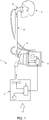
- Figure 1 shows a respiratory system 1 which can include, but is not limited to, the following components: a pressurized gases source 2, such as a blower or ventilator, adapted to generate a supply of gases to be delivered to a patient 3; a humidification device 4 adapted to condition the supply of gases; a medical tube 6 adapted to deliver the gases to a patient interface 8, which then delivers the gases to the patient 3; and a connector 16 adapted to connect the medical tube 6 to the humidification device 4.
- a pressurized gases source 2 such as a blower or ventilator
- the patient interface 8 as described herein may refer to a mask, nasal mask, nasal prongs, oral mask, tracheal mask, or nasal pillows.
- the humidification device 4 as described herein may refer to any device that conditions gases. This may include heating the gases and/or humidifying the gases.
- Gases as described herein may refer to air, oxygen, carbon dioxide, or a mixture of any such gases, or a combination of any such gases with one or more medicaments or aerosols that may be delivered to the patient 3 via the patient interface 8.
- the medical tube 6 as described herein may refer to a tube, conduit, circuit, or hose.
- the medical tube 6 illustrated may comprise a first elongate member 10 and a second elongate member 12.
- the medical tube 6 illustrated may comprise one or more wires 15.
- the one or more wires 15 may comprise at least one heater wire, at least one sensor wire, and/or any other type of electrical conductor.
- the one or more wires 15 may be within the medical tube 6.
- the one or more wires 15 may be lying along an inner or outer surface of the medical tube 6.
- the one or more wires 15 may be spirally wound onto the medical tube 6 or into the medical tube 6 such that the one or more wires 15 may be embedded in the wall of the medical tube 6.
- the medical tube 6 may be heated or unheated.
- the medical tube 6 may include insulation to reduce condensate from forming within the medical tube 6.
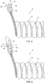
- the first elongate member 10 may provide such insulation. Condensate may form if the heated, humidified gases within the medical tube 6 cool down during transit. To reduce or eliminate condensate formation, the medical tube 6 may be heated. This heating may be provided by the one or more wires 15 comprising one or more heater wires 14, as shown in Figures 5 and 6 .
- the second elongate member 12 may comprise the one or more wires 15.
- a terminating portion of the medical tube 6 may be provided to terminate the one or more wires 15 at the connector 16 such that an electrical connection may be formed between the medical tube 6 and a component of the respiratory system 1.
- the terminating element may comprise a tail 20 or a tail 30, as illustrated in relation to the medical tube 6 in Figures 5 and 6 , and also as illustrated close up in Figures 3 and 4 .
- the connector 16 may provide a pneumatic connection between the medical tube 6 and a component of the respiratory system 1.
- a component of the respiratory system 1 as described herein may refer to a patient interface or a humidification device.
- the connector 16 may provide either one of or both an electrical and pneumatic connection between the medical tube 6 and a component of the respiratory system 1.
- the one or more wires 15 may also comprise one or more sensing wires 18, as illustrated in Figures 5 and 6 .
- the one or more sensing wires 18 may be used to sense gases properties such as temperature, flow, humidity, or pressure. In some embodiments, the one or more sensing wires 18 may be used to sense temperature. In some embodiments, the one or more sensing wires 18 may be connected to one or more sensors that may be used to sense one or more of these gases properties.
- the one or more wires 15 are embedded in the medical tube 6. In some embodiments, the one or more wires 15 may be embedded in the second elongate member 12. In some embodiments, the one or more wires 15 may be embedded in the first elongate member 10. In some embodiments, both the one or more heater wires 14 and the one or more sensing wires 18 may be embedded in the second elongate member 12. In some embodiments, both the one or more heater wires 14 and the one or more sensing wires 18 may be embedded in the first elongate member 10.
- At least one of the one or more heater wires 14 and the one or more sensing wires 18 may be embedded in the second elongate member 12, and at least one other of the one or more heater wires 14 and the one or more sensing wires 18 may be embedded in the first elongate member 10. In some embodiments, there may be no heater wires 14 within the second elongate member 12. In some embodiments, there may be no sensing wires 18 within the second elongate member 12. There may be any other such combination.
- the one or more heater wires 14 may comprise two heater wires. In some embodiments, the one or more sensing wires 18 may comprise two sensing wires. In some embodiments, the one or more sensing wires 18 may be located near the one or more heater wires 14. In some embodiments, the one or more heater wires 14 may comprise a first heater wire and a second heater wire, and the one or more sensing wires 18 may be located between the first heater wire and the second heater wire.
- the first elongate member 10 and the second elongate member 12 may be made from different materials.
- the first elongate member 10 may be flexible and/or may provide thermal insulation properties to the medical tube 6.
- the second elongate member 12, for example, may be made from material that provides reinforcing properties and/or structural support to the medical tube 6.
- the first elongate member 10 may provide reinforcing properties and/or structural support for the medical tube 6.
- the second elongate member 12 may be flexible and/or may provide thermal insulation properties. Different combinations may also be provided.
- the medical tube 6 may comprise a single elongate member.
- the medical tube 6 may comprise two or more first elongate members.
- the medical tube 6 may comprise two or more second elongate members.
- the tails 20, 30 may extend from the second elongate member 12, as illustrated in Figures 5 and 6 . In some embodiments, the tails 20, 30 may extend from the first elongate member 10. In some embodiments, the tails 20, 30 may extend from a combination of the first elongate member 10 and the second elongate member 12. Similarly, if greater than two elongate members are used, the tails 20, 30 may extend from any one of or from more than one elongate member in the system.
- the tails 20, 30 as described herein refer to terminating portions of the first elongate member 10 and/or the second elongate member 12 that have been adapted to enable connection of the first elongate member 10 and/or the second elongate member 12 to an electrical component.
- An electrical component may refer, for example, to a printed circuit board or an electrical connector.
- the tail 20 may comprise a flattened portion 22 and an exposed portion 24.
- the tail 20 may comprise a transition or preliminary portion, between the first elongate member 10 and/or the second elongate member 12 and the flattened portion 22, that is not flattened or is less flattened than the flattened portion 22.
- the tail 30 may comprise a first flattened portion 32, an exposed portion 34, and a second flattened portion 36.
- the tail 30 may comprise a transition or preliminary portion, between the first elongate member 10 and/or the second elongate member 12 and the first flattened portion 32, that is not flattened or is less flattened than the first flattened portion 32.
- the tails 20, 30 may comprise only the exposed portions 24, 34, respectively; however, the flattened portion 22, the first flattened portion 32, and/or the second flattened portion 36 may aid in handling and connection of the one or more wires 15 to an electrical component.
- the flattened portion 22 and/or the first flattened portion 32 may be made from the same material as the second elongate member 12.
- the width W of the flattened portion 22, the first flattened portion 32, and/or the second flattened portion 36 may be at most 11.0 mm, at most 9.0 mm, or at most 8.5 mm.
- the length L1 of the flattened portion 22 and/or the first flattened portion 32 may be at least 8.0 mm.
- the length L2 of the exposed portion 24 and/or the exposed portion 34 may be at least 8.0 mm or at least 10.0 mm.
- the length L3 of the second flattened portion 36 may be at least twice the length of the exposed portion 34, at most 32.0 mm, or at most 25.0 mm.
- the flattened portion 22 describes a portion of the tail 20, and the first flattened portion 32 describes a portion of the tail 30, wherein the one or more wires 15 may become spaced. Spacing as herein described may refer to the separation or moving apart of the one or more wires 15, and may refer to the location and position of the one or more wires 15 within the flattened portion 22, the first flattened portion 32, and/or the second flattened portion 36. If the one or more wires 15 comprises more than one wire - such as two or more heater wires, a combination of at least one heater wire and at least one sensing wire, two or more sensing wires, or any other combination of electrical conductors - then each of the one or more wires 15 may be spaced relative to each other.
- This spacing may be to aid attachment of the one or more wires 15 to an electrical component.
- This spacing may be determined by the width of the flattened portion 22 and/or the first flattened portion 32.
- the spacing between each of the one or more wires 15 may be 2.5 mm, at most 4.0 mm, or at least 1.0 mm.
- the distance between any two outermost wires may be less than 9.0 mm or less than 8.0 mm. A range of separation or spacing distances between each of the one or more wires 15 may be used.
- the flattened portion 22 and/or the first flattened portion 32 may extend beyond either side of the one or more wires 15.
- the flattened portion 22 and/or the first flattened portion 32 may encase the one or more wires 15.
- the amount of the flattened portion 22 and/or the first flattened portion 32 encasing the one or more wires 15 may be within a range of values.
- the flattened portion 22 and/or the first flattened portion 32 may extend by 0.25 mm on either side of the one or more wires 15.
- the flattened portion 22 and/or the first flattened portion 32 may extend on either side of the one or more wires 15 by more, or less, as required.
- the flattened portion 22 and the first flattened portion 32 of the second elongate member 12 may be formed using known flattening techniques.
- the length of the flattened material may be important with regard to spacing and to maintaining the spacing of the one or more wires 15. If the one or more wires 15 comprises more than one wire, the length of the flattened material that forms the flattened portion 22 and the first flattened portion 32 may help to space each of the one or more wires 15 relative to each other.
- Each of the one or more wires 15 may be spaced relative to each other before they are exposed. In some embodiments, the one or more wires 15 may be spaced relative to each other after they have been exposed. In some embodiments, each of the one or more wires 15 may be spaced from each other as they are exposed. Spacing of each of the one or more wires 15 relative to each other may reduce the likelihood that the order of the one or more wires 15 will be confused. This may aid an assembly operator with regards to usability and handling.
- the spacing between the wires can
- the exposed portions 24, 34 may be discrete portions that follow the flattened portion 22 or the first flattened portion 32, respectively.
- the one or more wires 15 may be exposed in the exposed portions 24, 34.
- the length of the exposed portions 24, 34 may be important.
- the exposed portions of the one or more wires 15 may be attached to an electrical component. Any suitable method to expose a portion of the flattened portion 22 and/or the first flattened portion 32 may be used.
- the exposed portions 24, 34 may have lengths that facilitate attachment of the one or more wires 15 to an electrical component.
- Figures 4 and 6 show embodiments in which the second flattened portion 36 may be used to facilitate attachment of the second elongate member 12 to an electrical component.
- the second flattened portion 36 may be located away from or at the other end of the exposed portion 34 relative to the first flattened portion 32.
- the second flattened portion 36 may cover the one or more wires 15 and may extend beyond the length of the one or more wires 15.
- the second flattened portion 36 may be useful in attaching the second elongate member 12 to an electrical component.
- the second flattened portion 36 may facilitate wrapping of the tail 30 around an electrical component and/or a connector, such as the connector 16.
- the second flattened portion 36 may also further maintain the spacing of the one or more wires 15 within the tail 30.
- the second flattened portion 36 may be made using the same material as the second elongate member 12. In some embodiments, the second flattened portion 36 may be made using a different material. The second flattened portion 36 may aid handling of the one or more wires 15. For example, it may not be necessary to handle each of the one or more wires 15 individually, which may improve the efficiency of assembling the medical tube 6 to a connector, such as the connector 16. In some embodiments, the second flattened portion 36 may be unused. Other mechanisms or techniques to maintain the positioning and spacing of the one or more wires 15 could be used.
- An electrical component may be attached to the one or more wires 15.
- the electrical component may be connected to the medical tube 6 by, for example, overmolding or adhesive, or by using a clipping mechanism.
- the connector 16 may form a connection between the medical tube 6 and an electrical component or another component of the respiratory system 1.
- the connector 16 may form a connection between the medical tube 6 and the humidification device 4.
- the connector 16 may form a connection between the medical tube 6 and the patient interface 8.
- the connector 16 may also be used to form a connection between the medical tube 6 and the blower 2.
- the connector 16 may be used to form an electrical and pneumatic connection between the medical tube 6 and at least one other medical tube.
- the medical tube 6 may be for infant, paediatric, or adult use.
- the medical tube 6 may be connected pneumatically to at least one other medical tube.
- the one or more wires 15 may be terminated at the connector 16 without forming an electrical connection.
- the tails 20, 30 may still be used in these embodiments to aid in connecting the medical tube 6 to the connector 16.
- the tails 20, 30 may be unused or may be omitted.
- known ways to attach the medical tube 6 to the connector 16 may be used.
- the connector 16 is not limited to the connections it may form, and other connections between a medical tube and a component of the respiratory system 1 may be arranged and configured in accordance with certain features, aspects and advantages of the present disclosure.
- a housing of the connector 16 may be formed from a transparent material.
- the transparent material may allow an operator to assess if the one or more wires 15 have been separated and/or positioned correctly on the connector 16.
- the housing of the connector 16 may be a coloured material.
- the housing of the connector 16 may be an opaque material, such that a user may be unable to see through the material.
- the tube 6 is illustrated in a configuration that defines a breathing tube 50.
- the illustrated breathing tube 50 has a chamber-end connector 52 and a patient-end connector 54.
- the chamber-end connector 52 can be configured as described in PCT/NZ2014/000201, filed September 15, 2014 (FPHCR.371WO) and PCT/NZ2013/000222, filed December 4, 2013 (FPCHR.273WO2).
- the patient-end connector 54 can be configured as described in PCT/NZ2013/000208, filed November 14, 2013 (FPHCR.335WO) and PCT/NZ2013/000222, filed December 4, 2013 (FPCHR.273WO2).
- the breathing tube 50 also comprises an intermediate connector 56.
- the intermediate connector 56 can be configured as described in PCT/NZ2013/000208, filed November 14, 2013 (FPHCR.335WO) and PCT/NZ2013/000222, filed December 4, 2013 (FPCHR.273WO2). While illustrated without outer covers, each of the connectors 52, 54, 56 can comprise suitable outer covers, for example as shown and described in Figures 10A , 11C , and 14F and the associated description, to provide an aesthetically pleasing outer appearance, to provide ergonomic outer surfaces for gripping or other manipulations, and to enshroud the components that define the electrical, mechanical, and pneumatic junctures described herein. In some configurations, the breathing tube 50 comprises more than one intermediate connector 56; other configurations of the intermediate connector 56 may be used.
- the intermediate connector 56 joins a first tube segment 60 and a second tube segment 62.
- the first tube segment 60 can be connected to the chamber-end connector 52 and the second tube segment 62 can be connected to the patient-end connector 54.
- an electrical path extends from the chamber-end connector 52 through the first tube segment 60 to the intermediate connector 56, across the intermediate connector 56, and from the intermediate connector 56 through the second tube segment 62 and to the patient-end connector 54.
- an unbroken electrical connection extends from the chamber-end connector 52 to the patient-end connector 54.
- a pneumatic path extends from the chamber-end connector 52 through the first tube segment 60 to the intermediate connector 56, through the intermediate connector 56, and from the intermediate connector 56 through the second tube segment 62 and to the patient-end connector 54.
- an unbroken pneumatic connection extends from the chamber-end connector 52 to the patient-end connector 54.
- An unbroken pneumatic connection can also extend from a pneumatic component (e.g., a humidifier chamber, not shown) connected to the chamber-end connector 52 through to a pneumatic component (e.g., a patient interface, not shown) connected to the patient-end connector 54. In effect, these components combine together to define a single medical tube that comprises two or more segments.
- the first tube segment 60 comprises a first end 64 and a second end 66. In some configurations, at least one of the first end 64 and the second end 66 comprises a tail 70. In some configurations, the first end 64 comprises the tail 70 while the second end 66 also comprises a tail 72.
- the tails 70, 72 can have any suitable configuration, including any of the configurations embodied by tails 20, 30.
- the second tube segment 62 comprises a first end 74 and a second end 76.
- at least one of the first end 74 and the second end 76 comprises a tail 80.
- the first end 74 comprises the tail 80 while the second end 76 also comprises a tail 82.
- the tails 80, 82 can have any suitable configuration, including any of the configurations embodied by tails 20, 30.
- the tube 6 in a configuration that defines a breathing tube 50 may comprise a chamber-end connector 52 and a patient-end connector 54, but does not comprise an intermediate connector.
- the tube 6 in a configuration that defines a breathing tube 50 can comprise a chamber-end connector 52, a patient-end connector 54, and a midpoint assembly.
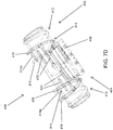
- An example embodiment of a midpoint assembly 400 is shown in Figures 7B-7D . Additional details regarding the midpoint assembly 400 are discussed below.
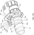
- the chamber-end connector 52 comprises a plug portion 90.
- the plug portion 90 can support a printed circuit board or PCB 92.
- the plug portion 90 comprises a main body 94.
- the main body 94 can be generally cylindrical.
- a mounting flange 96 can extend away from the main body 94.
- the mounting flange 96 can extend outward from the main body 94.
- the mounting flange 96 can define structure onto which the outer covers or housings can connect.
- the mounting flange 96 defines a passage 98 through which the printed circuit board 92 can extend.
- a shroud 99 extends from the mounting flange 96 and generally forms an extension of the passage 98 through with the PCB 92 extends.
- a support ledge 100 Adjacent to the passage 98, a support ledge 100 can be formed.
- the support ledge 100 is arranged and configured to underlie the printed circuit board 92.
- the support ledge 100 extends radially outward from the main body 94.
- the support ledge 100 is an axially extending ridge that extends radially outward from the main body 94.
- the support ledge 100 is connected to the mounting flange 96.
- the support ledge 100 can be reinforced by one or more buttresses 102. In the illustrated configuration, the support ledge 100 is reinforced by three buttresses 102. In the illustrated configuration, all of the buttresses 102 extend outward from a single side of the support ledge 100.
- the support ledge 100 can comprise an upturned hook 104.
- the upturned hook 104 can turn back toward the mounting flange 96.
- the upturned hook 104 is arranged and configured to overlie at least a portion of the printed circuit board 92.
- a protrusion can be positioned inside of the upturned hook 104, which protrusion extends in an axial direction and which protrusion can be received within a recess defined on the axial end of the printed circuit board 92.
- the upturned hook 104 has a larger lateral dimension than the support ledge 100.
- the upturned hook 104 and a portion of the support ledge 100 underlying the upturned hook 104 both have a larger lateral dimension than a portion of the support ledge 100 not underlying the upturned hook 104. In some configurations, the upturned hook 104 extends from an axial end of the support ledge 100.
- the printed circuit board 92 comprises one or more solder pads 106.
- the printed circuit board 92 can comprise attachment notches 108 that are at least partially surrounded by the solder pads 106.
- the attachment notches 108 can have any suitable configuration. In the illustrated configuration, the attachment notches 108 are positioned at locations that correspond to gaps positioned between the buttresses 102. In some configurations, the attachment notches 108 are positioned at locations that align with the gaps defined between the buttresses 102 when the end of the printed circuit board 92 is seated within the upturned hook 104.
- the printed circuit board 92 can also comprise wire alignment components, such as alignment notches 110, for example but without limitation.
- the attachment notches 108 are on one side of the printed circuit board 92 and the alignment notches 110 are on the opposite side of the printed circuit board 92.
- the alignment notches 110 can receive wires of the tail 70.
- the alignment notches 110 can generally align with the locations of the attachment notches 108.
- the alignment notches 110 can help to reduce or eliminate the likelihood of wires of the tail 70 crossing each other and can help to maintain wires of the tail 70 taut during soldering to the printed circuit board 92.
- two or more of the alignment notches 110 can be separated by a greater distance than the separation distance between the corresponding attachment notches 108, causing wires of the tail 70 to fan out from the attachment notches 108 to the alignment notches 110 in order to improve access for soldering and to further reduce the likelihood of wires of the tail 70 crossing each other.
- the alignment notches 110 can be sized and configured to accommodate wires of the tail 70. While the alignment notches 110 are illustrated as a portion of the printed circuit board 92, the alignment notches 110 can be formed of a separate component, such as the support ledge 100 or the upturned hook 104, for example but without limitation.
- the upturned hook 104 can help resist twisting of the printed circuit board 92 when the tail 70 is pulled into position such that wires of the tail 70 are secured within the attachment notches 108 and the alignment notches 110.
- the buttresses 102 can help reduce the likelihood of bending or warping of the printed circuit board 92 during soldering of wires of the tail 70 to the solder pads 106.
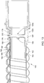
- the conduit 112 can have any suitable configuration, including any configuration described elsewhere herein.
- the illustrated conduit 112 comprises a first element 114 and a second element 116.
- the first element 114 may terminate before the second element 116, with the tail 70 extending from the second element 116.
- the tail 70 of the second element 116 may extend further along the plug portion 90 than the first element 114.
- the tail 70 may extend from the first element 114.
- the tail 70 may extend from a combination of the first element 114 and the second element 116.
- the first element 114 and the second element 116 are helically wound at a certain pitch.
- the second element 116 can comprise a bead that incorporates one or more wires 118.
- the wires 118 can have any suitable configuration. In some configurations, the wires 118 can be coated to have two or more colors. In other words, in some configurations, the wires 118 can be variantly coated or otherwise colored such that some of the wires 118, e.g., the outermost of the wires 118, can be visually distinguished from other of the wires 118, e.g., the innermost of the wires 118.
- Such a configuration, or another configuration that allows visual distinction between or among the wires 118, advantageously allows verification that the wires 118 are in a desired location and order in the respective attachment notches 108 prior to being soldered to the solder pads 106 of the printed circuit board 92.
- the tail 70 can comprise a first flattened region 120 and a second flattened region 122, and the wires 118 can be exposed between the first flattened region 120 and the second flattened region 122.
- the tail 70 thus, can have any suitable configuration, including any of those described herein.
- the second flattened region 122 can be omitted.
- the first flattened region 120 and the second flattened region 122 can be omitted.
- the first flattened region 120 and the second flattened region 122 help to reduce the likelihood of contact between the wires 118 during or following manufacture.
- the tail 70 can comprise a transition or preliminary portion, between the first element 114 and/or the second element 116 and the first flattened region 120, that is not flattened or is less flattened than the first flattened region 120.
- the second flattened region 122 can be restrained in position during manufacture using a cover 124.
- the cover 124 can be integrally formed with the plug portion 90.
- the cover 124 can be formed separate of the plug portion 90.
- the separately formed cover 124 can be secured to the plug portion 90 in any suitable configuration.
- a living hinge 126 can be used to secure the integrally formed cover 124 to the plug portion 90.
- Other suitable configurations also can be used.
- the cover 124 can comprise a curved inner surface 128.
- the curved inner surface 128 can be used to secure at least a portion of the second flattened region 122 against an outer surface 130 of the plug portion 90.
- a least a portion of the second flattened region 122 can be secured between the outer surface 130 of the plug portion 90 and the curved inner surface 128 of the cover 124.
- at least a portion of the first flattened region 120 can be secured between the outer surface 130 of the plug portion 90 and the inner surface 128 of the cover 124.
- at least a portion of the wires 118 exposed between the first flattened region 120 and the second flattened region 122 can be secured between the outer surface 130 of the plug portion 90 and the inner surface 128 of the cover 124.
- the cover 124 can comprise one or more retention members 132.
- two retention members 132 are provided.
- Each of the retention members 132 can comprise a hook member 134.
- the two retention members 132 can be separated from each other by a tab 136.
- the tab 136 can provide a surface for the operator to press to close the cover 124 against the plug portion 90.
- the tab 136 can also cover at least a part of the second flattened region 120 when the cover 124 is closed against the plug portion 90.
- Other configurations can be used that do not comprise the tab 136, keeping in mind the desire to provide for ease of assembly and coverage of the second flattened region 120.
- the plug portion 90 can comprise one or more catches 138.
- the catches 138 can be positioned on the support ledge 100.
- the catches 138 can be positioned on a lower surface of the support ledge 100.
- Other configurations are possible keeping in mind a desire to secure the cover 124 in a closed position that captures the second flattened region 122.
- the cover 124 can be rotated about the living hinge 126 until the retention members 132 engage with the catches 138, which traps the second flattened region 122 between the outer surface 130 and the curved inner surface 128 of the cover 124.
- connection between the conduit 112 and the plug portion 90 and/or the connection between the wires 118 and the printed circuit board 92 can be overmolded.
- the cover 124 can be overmolded.
- connection between the conduit 112 and the plug portion 90, as well as the connection between the wires 118 and the printed circuit board 92, and the cover 124 can be overmolded.
- a flow of an overmold material 142 can be limited during overmolding.
- the overmold material 142 can be any suitable material.
- the overmold material 142 can be any material suitable for use in lower pressure overmolding.
- the overmold material 142 can be a thermoplastic elastomer (TPE), such as a thermoplastic polyurethane (TPU), a thermoplastic vulcanizate (TPV), or a polyolefin elastomer (POE), similar to or the same as the material used to form the tube 6.
- TPE thermoplastic elastomer
- TPU thermoplastic polyurethane
- TPV thermoplastic vulcanizate
- POE polyolefin elastomer
- the overmold material 142 can be a thermoplastic polymer such as a low-density polyethylene (LDPE) or a polypropylene (PP).
- LDPE low-density polyethylene
- PP polypropylene
- the overmold material 142 can be an ethylene copolymer with a methylacrylate component, which bonds to the plug portion 90, the tails 70, 72, and the printed circuit board 92 and thereby provides pneumatic leak protection and liquid ingress protection.
- the printed circuit board 92 may be insert-molded as part of, or otherwise bonded to, the plug portion 90, and the overmold material 142 can be a thermoplastic elastomer selected to bond to the plug portion 90 and the tails 70, 72.
- the overmold material 142 can flow into at least a portion of the first element 114.
- the first element 114 can be an elongate hollow element and the overmold material 142 can flow into at least a portion of the elongate hollow element to help reduce the likelihood of leaks.
- the overmold material 142 can at least partially melt the second element 116. By at least partially melting the second element 116, the overmold material 142 and the second element 116 can help to reduce the likelihood of leaks.
- the overmold material 142 can provide protection to the electrical components (e.g., can effectively pot the electrical components).
- the plug portion 90 can comprise a guidance tab 144.
- the guidance tab 144 can be integrally formed with the plug portion 90.
- the guidance tab 144 can act as a positive stop for the conduit 112 during assembly of the conduit 112 onto the plug portion 90.
- the plug portion 90 comprises a helical rib 146.
- the helical rib 146 can align with the pitch of the conduit 112. The plug portion 90 can be inserted into the conduit 112 until the guidance tab 144 is positioned between the tail 70 and the conduit 112. The helical rib 146 can then help to hold the conduit 112 in place on the plug portion 90 by pressing into the first element 114.
- the guidance tab 144 is bent toward the mounting flange 96. which can help direct the tail 70 towards the printed circuit board 92. Because the length of the tail 70 and the length of the first flattened region 120 are known, it is possible to provide a desired length between the end of the first element 114 and the point of connection of the exposed wires 118 to the solder pads 106 of the printed circuit board 92. Other configurations are possible keeping in mind a desire to properly locate the terminal end of the conduit 112 relative to the printed circuit board 92.
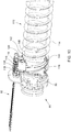
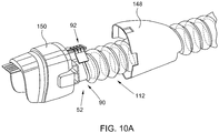
- the assembly discussed above - including but not limited to portions of the chamber-end connector 52, portions of the conduit 112, and/or portions of the printed circuit board 92 - can be encapsulated by a first outer cover 148 and a second outer cover 150.
- the two outer covers 148, 150 can be secured in any suitable manner. In the illustrated configuration, the two outer covers 148, 150 can be snap-fit to the mounting flange 96 of the plug portion 90. Other configurations are possible.
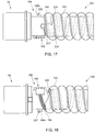
- Figures 11A-11C illustrate another example embodiment of a chamber-end connector 352.
- Figures 11A-11B illustrate the chamber-end connector 352 without an outer cover or housing
- Figure 11C illustrates the chamber-end connector 352 encapsulated by a first outer cover 348 and a second outer cover 350 that are secured to each other and/or underlying components of the connector 352.
- the chamber-end connector 352 comprises a plug portion 390 that can support a printed circuit board or PCB 392.
- the plug portion 390 comprises a main body 394 that can be generally cylindrical.
- a mounting flange 396 can extend away from the main body 394.
- the mounting flange 396 defines a passage 398 through which the PCB 392 can extend.
- the mounting flange 396 also defines an extension 398a of the passage 398 extending from the passage 398, and extending from the PCB 392 when the PCB 392 extends through the passage 398.
- an electronic component 93 such as but not limited to an ID resistor
- an electronic component 393 is positioned on the PCB 392 on the conduit side of the mounting flange 396, i.e., on the same side of the mounting flange 396 as alignment notches 310.
- Placement of the electronic component 393 on the conduit side of the mounting flange 396 allows the electronic component 393 to be covered by the overmold material as described herein to advantageously help protect the electronic component 393 from liquid.
- the extension 398a of the passage 398 provides an opening for the electronic component 393 to pass through the mounting flange 396 during assembly.
- a support ledge 300 can be formed adjacent to the passage 398.
- the support ledge 300 is arranged and configured to underlie and support the PCB 392.
- the support ledge 300 has a height that is 0.02 to 0.1 mm higher, i.e., farther from the central axis of the plug portion 390, than the bottom of the passage 398. This increased height causes the portion of the PCB 392 on the conduit side of the mounting flange 396 to bend or lift slightly upwards, i.e., away from the central axis of the plug portion 390.
- the portion of the PCB 392 on the chamber side of the mounting flange 396 to be deflected or bent slightly downward, i.e., closer to the central axis of the plug portion 390, which forces the chamber end of the PCB 392, i.e., the end of the PCB 392 on the chamber side of the mounting flange 396, more tightly into contact with the underlying surface of the chamber-end connector 352.
- the second outer cover 350 configured to enclose portions of the plug portion 390 and the PCB 392 comprises a ledge 351.
- the ledge 351 is configured to underlie and support the chamber end of the PCB 392.
- the height of the support ledge 300 pressing upward on the portion of the PCB 392 on the conduit side of the mounting flange 396 drives the portion of the PCB 392 on the chamber side of the mounting flange 396 downwards, which helps promote the chamber end of the PCB 392 lying flush with, or slightly below the upper surface of, the ledge 351. This helps inhibit the PCB 392 from potentially being snagged on surrounding objects and reduces the likelihood of separation between the PCB 392 and the ledge 351.
- the ledge 351 can contain a recess that receives at least a portion of the PCB 392.
- the support ledge 300 is reinforced by two buttresses 302.
- the support ledge 300 can comprise an upturned hook 304 to overlie a portion of the PCB 392.
- the PCB 392 comprises one or more attachment notches 308, solder pads 306 that at least partially surround the attachment notches 308, and alignment notches 310.
- the PCB 392 comprises four attachment notches 308 at least partially surrounded by four solder pads 306 and four corresponding alignment notches 310.
- the outermost two attachment notches 308a and solder pads 306a are positioned on a first edge of the PCB 392, and the corresponding outermost two alignment notches 310a are positioned on the second, opposing edge of the PCB 392 in alignment with the attachment notches 308a.
- the inner two attachment notches 308b and solder pads 306b are positioned on the second edge of the PCB 392 between the outer alignment notches 310a, and the inner two alignment notches 310b are positioned on the first edge of the PCB 392 between the attachment notches 308a and in alignment with the attachment notches 308b.
- the outer solder pads 306a are configured to be soldered to the heater wires 14, and the inner solder pads 306b are configured to be soldered to the sensing wires 18. Soldering the heater wires 14 to the outer solder pads 306a and on the opposite edge of the PCB 392 from the sensing wire solder pads 306b advantageously increases the separation between the heater wire solder pads 306a and the sensing wire solder pads 306b. This helps inhibit or reduce the likelihood of liquid bridging between the heater wire solder pads 306a and the sensing wire solder pads 306b and thus shorting the heater wires 14 to the sensing wires 18.
- the PCB 392 also comprises a slot 395.
- the slot 395 extends lengthwise along a portion of the PCB 392 on the conduit side of the PCB 392.
- the slot 395 is positioned between the outer solder pads 306a and the inner solder pads 306b.
- overmold material flows into the slot 395, which also helps to separate the heater wire solder pads 306a from the sensing wire solder pads 306b and helps to inhibit liquid from bridging between them.
- the separation between the heater wire solder pads 306a and the sensing wire solder pads 306b also helps to reduce the likelihood of heat transfer between the heater wires and the sensing wires.
- the chamber-end connector 352 of Figures 11A-11C can also comprise a cover (not shown) configured to restrain the second flattened region 122 during manufacture.
- the cover can be similar to the cover 124 shown in Figures 8 and 9 .
- the cover for the embodiment shown in Figures 11A-11C may only comprise one retention member 132. In other words, the cover may attach to only one end of the support ledge 300 rather than attaching to two ends of the support ledge 300.
- portions of and/or connections among the plug portion 390, the wires 118, the conduit 112, and the PCB 392 can be overmolded similar to the embodiment of Figures 8-10A .
- the electronic component 393 can also be overmolded due to the placement of the electronic component 393 on the conduit side of the PCB 392.
- the plug portion 390 can comprise a partitioning wall 397 as shown in Figures 11A-11B .
- the partitioning wall 397 divides the space below the PCB 392 between the mounting flange 396 and the buttresses 302 of the support ledge 300. The division of this space into two smaller spaces by the partitioning wall 397 advantageously helps reduce the likelihood of the overmold material forming voids or shrinking excessively as it cools.
- the plug portion 390 can comprise a guidance tab 344 that can act as a positive stop for the conduit 112 during assembly of the conduit 112 onto the plug portion 390.
- the guidance tab 344 protrudes from the plug portion 390 normal to the plug portion 390 wall rather than at an angle as in the embodiment of Figures 8-10A .
- the plug portion 390 comprises two helical ribs 346, 347. In some embodiments, the first helical rib 346 and/or the second helical rib 347 can align with the pitch of the conduit 112.
- the second helical rib 347 has a roughly trapezoidal cross section that creates a sharp transition or change in slope from the outer surface of the plug portion 390 to the outer surface of the second helical rib 347, whereas the first helical rib 346 has a roughly semicircular cross section that creates a smoother transition.
- the sharp angles of the second helical rib 347 can help prevent or reduce the likelihood of liquid passing over the second helical rib 347.
- the plug portion 390 can be inserted into the conduit 112 until the guidance tab 344 is positioned against a cut portion of the first element 114.
- the first helical rib 346 can then help to hold the conduit 112 on the plug portion 90 by pressing into the first element 114.
- the guidance tab 344 can extend from the first helical rib 346.
- the second helical rib 347 is positioned between the first helical rib 346 and the support ledge 300. As shown in Figure 11A , the second helical rib 347 comprises a longitudinal bridging segment 347a such that the second helical rib 347 fully encircles the plug portion 390.
- the second helical rib 347 can act as a liquid barrier to inhibit liquid from transferring from the conduit 112 toward the PCB 392.
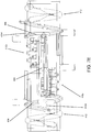
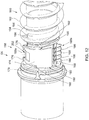
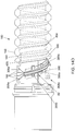
- the patient-end connector 54 is shown coupled to an end of a conduit 160.
- the patient-end connector 54 can comprise a single integrally formed main body 158. Other configurations also are possible.
- the conduit 160 can have any suitable configuration, including any configuration described elsewhere herein.
- the illustrated conduit 160 comprises a first element 162 and a second element 164.
- the first element 162 may terminate before the second element 164, with the tail 82 (not visible in Figure 12 ) extending from the second element 164.
- the tail 82 of the second element 164 may extend further along the main body 158 of the patient-end connector 54 than the first element 162.
- the tail 82 may extend from the first element 162.
- the tail 82 may extend from a combination of the first element 162 and the second element 164.
- the first element 162 and the second element 164 are helically wound with a certain pitch.
- the second element 164 can comprise a bead that incorporates one or more wires 166.
- the wires 166 can have any suitable configuration. In some configurations, the wires 166 can be coated to have two or more colors. In other words, in some configurations, the wires 166 can be variantly coated or otherwise colored such that some of the wires 166, e.g., the outermost of the wires 166, can be visually distinguished from other of the wires 166, e.g., the innermost of the wires 166. Such a configuration, or another configuration that allows visual distinction between or among the wires 166, advantageously allows verification that the wires 166 are in a desired location and order for connection to a printed circuit board 168.
- the tail 82 can comprise a first flattened region 170 and a second flattened region 172 (not visible in Figure 12 ), and the wires 166 can be exposed between the first flattened region 170 and the second flattened region 172.
- the tail 82 thus, can have any suitable configuration, including any of those described elsewhere herein.
- the second flattened region 172 can be omitted.
- the first flattened region 170 and the second flattened region 172 can be omitted. The first flattened region 170 and the second flattened region 172, however, help to reduce the likelihood of contact between the wires 166 during or following manufacture.
- the tail 82 can comprise a transition or preliminary portion, between the first element 162 and/or the second element 164 and the first flattened region 170, that is not flattened or is less flattened than the first flattened region 170.
- the second flattened region 172 can be restrained in position during manufacture using a cover 174.
- the cover 174 can be integrally formed with the main body 158.
- the cover 174 can be formed separate of the main body 158.
- the separately formed cover 174 can be secured to the main body 158 in any suitable configuration.
- a living hinge 176 can be used to secure the integrally-formed cover 174 to the plug portion 90.
- two separate living hinges 176 have been used.
- Other suitable configurations also can be used.
- the second flattened region 172 can be cut off after the exposed wires 118 have been soldered to the solder pads 106, and no cover is used.
- the cover 174 comprises a first edge 188 and a second edge 190 and comprises a recess 178 that can be positioned along the first edge 188.
- a post 180 of the main body 158 can be used to secure the cover 174 in a closed position.
- the post 180 and the recess 178 can interact to secure the cover 174 in the closed position.
- a spine 192 can align with the pitch of the conduit 160.
- the second edge 190 can align with the pitch of (or extend generally parallel to) the spine 192.
- the second edge 190 and the spine 192 when thus aligned, can interact to help secure the cover 174 in the closed position by preventing movement of the recess 178 away from the post 180.
- the cover 174 can secure the second flattened region 172 and/or the wires 166 in position between the main body 158 and the cover 174.
- the main body 158 can comprise a wire alignment component, such as a comb 182, for example but without limitation.
- the comb 182 can comprise a plurality of fingers spaced by gaps or alignment notches that receive the wires 166.
- the comb 182 can help to reduce or eliminate the likelihood of the wires 166 crossing each other and can help to maintain the wires 166 taut during soldering to the printed circuit board 168.
- the comb 182 extends generally normal to the printed circuit board 168.
- the printed circuit board 168 preferably extends fully through the diameter of the main body 158. In other words, at least a portion of the printed circuit board 168 can be exposed beyond the main body 158 at either or both ends of the printed circuit board 168. As illustrated in Figure 13 , the printed circuit board 168 has a wider head part 168b and a narrower stem part 168a that extends through the gases flow path of the main body 158. At least a portion of the head part 168b preferably extends beyond the main body 158. In some embodiments, as illustrated in Figure 13 , at least a portion of the stem part 168a extends beyond the main body 158.
- the stem part 168a extends into a thickness of the main body 158 but not beyond the main body 158.
- the stem part 168a joins to the head part 168b within a thickness of the main body 158.
- at least a portion of the head part 168b is embedded within the wall of the main body 158, as shown in Figure 13 .
- the head part 168b comprises the solder pads 106, and embedding a portion of the head part 168b into the wall of the main body 158 helps the printed circuit board 168 to resist flexure during assembly.
- the printed circuit board 168 is shown with a thermistor 184 attached to the printed circuit board 168.
- the thermistor 184 can be a surface mount thermistor. Other sensors can be mounted to the printed circuit board 168.
- the thermistor 184 is used to sense temperature and to feed a value representing the temperature back to the printed circuit board 168 and from the printed circuit board 168 to a further medical device.
- the thermistor 184 as well as the printed circuit board 168 can be overmolded during formation of the patient-end connector 54. Because of the clamping and material flow pressures that occur during the overmolding process, the orientation of the components and the bending or flexure of the printed circuit board 168 become important considerations. For this reason, the thermistor 184 is mounted lengthwise in the direction of gases flow through the patient-end connector 54. The lengthwise mounting in the direction of gases flow reduces the impact of possible flexure of the printed circuit board 168 during the overmolding operation. In other words, the thermistor 184 preferably is mounted with the terminals oriented relative to each other in a direction that has the least amount of flexure of the printed circuit board 168.
- the thermistor 184 can be positioned on an extended portion of the printed circuit board 168 that extends further upstream into the gases flow relative to other portions of the printed circuit board 168 and the mounting of the printed circuit board 168 to the main body 158. By positioning the thermistor 184 on this extended portion of the printed circuit board 168, the thermistor 184 will be positioned in a more laminar gases flow, before the turbulence in the gases flow that can be created by the other portions of the printed circuit board 168 and the mounting of the printed circuit board 168 to the main body 158.
- thermoelectric thermistor 184 on the extended portion of the printed circuit board 168 can help to reduce the impact of stem effects on the readings from the thermistor 184 that can be caused by temperature variations generated by other electronic components on the printed circuit board 168 and/or ambient conditions.
- the main body 158 can comprise a guidance tab 186.
- the guidance tab 186 can be integrally formed with the main body 158.
- the guidance tab 186 can act as a positive stop during assembly of the conduit 160 onto the main body 158.
- the main body 158 comprises a helical rib 194
- the helical rib 194 can match or simulate the pitch of the conduit 160.
- the conduit 160 can be threaded onto the main body 158 (or the main body 158 can be threaded into the conduit 160) until the first element 162 (e.g., the elongate hollow portion of the conduit 160) bumps against the guidance tab 186.
- the guidance tab 186 may be bent away from the body of the conduit 160, which can help direct the tail 82 towards the printed circuit board 168. In some embodiments, the guidance tab 186 protrudes normal to the main body 158. Because the length of the tail 82 and the length of the first flattened region 170 are known, it is possible to provide a desired length between the end of the first element 162 and the connection of the exposed wires 166 to the solder pads 106 of the printed circuit board 168. Other configurations are possible keeping in mind a desire to properly locate the terminal end of the conduit 160 relative to the printed circuit board 168.
- connection between the conduit 160 and the main body 158 and/or the connection between the printed circuit board 168 and the wires 166 can be overmolded.
- an overmold material 189 is shown at the juncture between the conduit 160 and the main body 158.
- the overmold material 189 can envelop the printed circuit board 168 and the wires 166.
- the overmold material 189 can be similar to, and have similar characteristics to, the overmold material 142 described above.
- a cover member can connect to the main body 158 to enshroud the connection between the conduit 160 and the main body 158.
- the intermediate connector 56 also can employ similar connections to the wires 166 and the conduit 160.
- the main body 158 can comprise features to allow the overmold material 189 to flow into any gaps to help seal the interface between the conduit 160 and the main body 158.
- the overmold material 189 can therefore help better protect the electrical components from condensate or other liquids.
- the overmold material 189 can also help create an improved pneumatic seal between the conduit 160 and the main body 158.
- Figures 15-19 illustrate example embodiments of such features.
- the patient-end connector 54 comprises a bridge piece 210.
- the bridge piece 210 can be disposed on the outer surface of the main body 158.
- the bridge piece 210 can be positioned between the outer surface of the main body 158 and at least a portion of the conduit 160.
- the bridge piece 210 can be positioned between the outer surface of the main body 158 and the second element 164 or bead of the conduit 160.
- Figure 16 illustrates a perspective view of the bridge piece 210.
- the bridge piece 210 comprises a pad portion 212, an extension portion 214, and a peg 216.
- the pad portion 212 can be generally square or rectangular. Other configurations also are possible.
- the pad portion 212 has a lower surface that is configured to contact the connector.
- the pad portion 212 has an upper surface that is configured to contact the conduit 160 or the second element 164 or bead of the conduit 160.
- the extension portion 214 extends outward and upward from the pad portion 212.
- the extension portion 214 is generally triangular, although other shapes or configurations are also possible.
- the extension portion 214 has a side surface.
- the peg 216 extends from the extension portion 214. In the illustrated configuration, the peg 216 extends from the side surface of the extension portion 214.
- the stem part 168a of the printed circuit board 168 extending from the main body 158 comprises a hole 202.
- the peg 216 is configured to be received in the hole 202, as shown in Figure 15 .
- the bridge piece 210 is coupled to the main body 158.
- the stem part 168a of the printed circuit board 168 is extended or slightly widened to provide additional strength and better support to the peg 216 and the bridge piece 210.
- the bridge piece 210 is positioned on the main body 158 proximate and proximal to the guidance tab 186.
- the bridge piece 210 is positioned such that the second element 164, comprising the bead, extends over the pad portion 212 when the conduit 160 is coupled to the main body 158.
- the pad portion 212 therefore causes the second element 164 to lift away from the outer surface of the main body 158, thereby creating a gap between the second element 164 and the outer surface of the main body 158 on either side of the pad portion 212 (i.e., in the circumferential direction of the connector).
- the overmold material 189 When the overmold material 189 is applied to the juncture between the conduit 160 and main body 158, the overmold material 189 can flow into the gaps created by the bridge piece 210, thereby bonding the second element 164 to the outer surface of the main body 158. Bonding the second element 164 to the outer surface of the main body 158 can inhibit or prevent liquid from seeping between the outer surface of the main body 158 and the second element 164 or bead of the conduit 160 and thus can reduce or eliminate the likelihood of liquid reaching the electrical connections.
- Figure 20 illustrates an alternative embodiment in which a bridge member is formed on the main body 158 by two neighboring recesses 211 positioned between the stem part 168a and the tab 186.
- the second element 164 extends over the recesses 211, allowing overmold material to flow into the recesses 211 such that the overmold surrounds the second element 164 and bonds the second element 164 to the outer surface of the main body 158. Bonding the second element 164 to the outer surface of the main body 158 can inhibit or prevent liquid from seeping between the outer surface of the main body 158 and the second element 164 to reduce or eliminate the likelihood of liquid reaching the electrical connections.
- the patient-end connector 54 comprises a channel 220 formed in the main body 158.
- the channel 220 allows the overmold material 189 to flow between the inner surface of the conduit 160 and the outer surface of the main body 158.
- the channel 220 is recessed from, or formed as a recess in, the outer surface of the main body 158.
- the channel 220 can have any suitable configuration.
- the channel 220 can extend around at least a portion of a circumference of the main body 158. In some configurations, the channel 220 can extend in a spiral or a partial spiral.
- the channel 220 can be positioned and formed such that the second element 164 extends over, along, or in the channel 220.
- the overmold material 189 When the overmold material 189 is applied to the juncture between the conduit 160 and the main body 158, the overmold material 189 can flow into the channel 220 and under the second element 164, thereby bonding the second element 164 to the outer surface of the main body 158. In some configurations, the overmold material 189 bonds the second element 164 or the conduit 160 to the recessed surface defined by the channel 220.
- the channel 220 and the second element 164 can be positioned so that the channel 220 extends to both sides of the second element 164 (i.e., in an axial direction of the connector). As shown in Figure 17 , at least a portion 222 of the channel 220 is proximal of the second element 164. In some configurations, the channel 220 can extend below more than one wrap of the helically winding second element 164. In some configurations, a lip or a ridge 224 can be configured along or adjacent to the channel 220 and the lip or ridge 224 can be oriented to extend across the second element 164. The lip or ridge 224 can lift the second element 164 away from the outer surface of the main body 158 similar to the pad discussed above.
- FIGS 14A-14F illustrate another example embodiment of a patient-end connector 354.
- the patient-end connector 354 can comprise an integrally formed main body 358 and printed circuit board or PCB 368.
- the second flattened region 172 of the tail 82 is cut off after the exposed wires 118 are soldered to the solder pads, and therefore no cover is used.
- the main body 358 can comprise a wire alignment component, such as a comb 382.
- the comb 382 can comprise alignment notches that receive the wires 166 to help keep the wires 166 separated from each other and taut during soldering to the PCB 368.
- the PCB 368 extends through the diameter of the main body 358 and comprises a wider head part 368b and narrower stem part 368a.
- the head part 368b comprises solder pads 306.
- the outer two solder pads 306a are positioned on the side of the head part 368b facing away from the comb 382 and the inner two solder pads 306b are positioned on the opposite side of the head part 368b, i.e., facing the comb 382.
- the outer two solder pads 306a can be configured to be soldered to the heater wires 14, and the inner two solder pads 306b can be configured to be soldered to the sensing wires 18. This arrangement advantageously increases the separation between the heater wire solder pads 306a and the sensing wire solder pads 306b to help reducing the likelihood of liquid bridging between them and potentially causing a short.
- the patient-end connector 354 can comprise a first helical rib 494 that helps to hold the conduit 160 on the main body 358 during assembly by pressing into the first element 162, a guidance tab 386 that acts as a stop for the conduit 160 during assembly of the conduit 160 onto the main body 358, and a second helical rib 495 that acts as a liquid barrier to inhibit liquid from the conduit 160 from reaching the PCB 368.
- the guidance tab 386 protrudes from the main body 358 normal to the main body 358.
- the first element 162 of the conduit 160 at the end of the conduit 160 threaded onto the connector 352 can be cut in the middle of the first element 162, and the main body 358 can be inserted into the conduit 160 until guidance tab 386 is positioned against the cut edge of the first element 162.
- the second helical rib 495 comprises a longitudinal bridging segment 495a so that the second helical rib 495 completely encircles the main body 358 to create a liquid barrier.
- the guidance tab 396 is positioned at the end of the longitudinal bridging segment 495a closest to the first helical rib 494.
- a drift limit post 388 is positioned at the opposite end of the longitudinal bridging segment 495a from the guidance tab 396.
- the tail 82 extends over the longitudinal bridging segment 495a as it extends to the PCB 368.
- the drift limit post 388 helps inhibit the tail 82 from drifting too far toward the stem part 368a of the PCB 368 to help keep the tail 82 in the desired location during overmolding.
- the stem part 368a of the PCB 368 is offset or not centered relative to the head part 368b. This advantageously shifts the exposed end of the stem part 368a farther away from the drift limit post 388.
- connection between the conduit 160 and the main body 358 of the patient-end connector 354 and/or the connection between the conduit 160 and the PCB 368 can be overmolded.
- the patient-end connector 354 can comprise features to allow overmold material to flow into any gaps to better seal the interface between the conduit 160 and the main body 358.
- the main body 358 comprises a series of bridge members that lift the tail 82 away from the main body 358 to allow the overmold material to fully encapsulate the tail 82.
- the longitudinal bridging segment 495a of the second helical rib 495 forms the first bridge member.
- Two additional bridge members 389a, 389b are positioned between the longitudinal bridging segment 495a and the head part 368b of the PCB, although more or fewer bridge members are also possible.
- the main body 358 can have a reduced outer diameter in the region surrounding the bridge members. For example, as shown in Figure 14E , the outer diameter can be reduced (compared to a diameter the main body 358 would have if circular, indicated by reference arc D in Figure 14E ) in the area 358a adjacent to the drift limit post 388 between the drift limit post 388 and bridge member 389a.
- the outer diameter can then gradually increase from region 358a to the region 358b adjacent the head part 368b of the PCB 368.
- This decreased outer diameter portion of the main body 358 can also help allow more overmold material to flow under the tail 82 to more completely encapsulate the tail 82.
- a cover member 355 can also connect to the main body 358 to enshroud the connection between the conduit 160 and the main body 358.
- FIGS 7B-7D illustrate an example embodiment of a midpoint assembly 400 that can be used to couple two conduit segments, such as the conduit segments 60 and 62 shown in Figure 7 .
- the midpoint assembly 400 as illustrated comprises a main body 402, a PCB 404, and a power diode 401.
- the midpoint assembly 400 may also comprise a sensor diode and a sensor, such as a thermistor.
- the midpoint assembly 400 can comprise various features similar in structure and/or function to those of the chamber-end connector 352 and the patient-end connector 354 shown and described herein, although the midpoint assembly 400 can comprise two each of many of these features, one at either end, as the midpoint assembly 400 is configured to couple to conduits at each end.
- the midpoint assembly 400 comprises two alignment components, such as combs 410a, 410b.
- the first comb 410a extends generally perpendicularly to the PCB 404 on one side of the PCB 404
- the second comb 410b extends generally perpendicularly to the PCB 404 on the other side of the PCB 404.
- solder pads 406 are alternated on either side of the PCB 404 to advantageously increase the separation between the adjacent solder pads 406 on each side of the PCB 404 to reduce the likelihood of shorts.
- Each end of the midpoint assembly 400 comprises a first helical rib 412 that allows for the conduit to be threaded onto the main body 402 and a second helical rib 414 that acts as a liquid barrier between the conduit and the PCB 404 and comprises a longitudinal bridging segment 414a so that the second helical rib 414 completely encircles the main body 402.
- Each end also comprises a guidance tab 416 at one end of the longitudinal bridging segment 414a.
- Each end further comprises two bridging members 420 that lift tails of the conduit segments away from the main body 402 to allow overmold material to fully encapsulate the tails.
- Figures 7E-7F illustrate another example embodiment of a midpoint assembly.
- the illustrated midpoint assembly can be similar to the midpoint assembly 400 of Figures 7B-7D .
- the first helical rib 412 and second helical rib 414 on the chamber end of the midpoint assembly and the first helical rib 412 and second helical rib 414 on the patient end of the midpoint assembly begin and end at substantially (e.g., within 5° or 10°) the same circumferential location.
- the longitudinal bridging segments 414a on the chamber and patient ends of the midpoint assembly can be positioned at substantially (e.g., within 5° or 10°) the same circumferential location.
- the start and end of the first 412 and second 414 helical ribs on one of the chamber end and patient end of the midpoint assembly are offset or displaced in a circumferential direction relative to the start and end of the first 412 and second 414 helical ribs on the other of the chamber end and patient end of the midpoint assembly.
- the longitudinal bridging segment 414a on one of the chamber and patient ends of the midpoint assembly is offset or displaced in a circumferential direction relative to the longitudinal bridging segment 414a on the other of the chamber and patient ends of the midpoint assembly.
- the start and end of the first and second helical ribs and/or the longitudinal bridging segment on one of the chamber and patient ends of the midpoint assembly is offset or displaced by 90° in a circumferential direction relative to the start and end of the first and second helical ribs and/or the longitudinal bridging segment on the other of the chamber and patient ends.
- This arrangement advantageously allows the chamber end connector, midpoint assembly, and patient end connector to be placed in an assembly jig in the correct orientation during manufacturing without kinking one of the tube segments.
- the midpoint assembly can include an indicator to show an orientation of the midpoint assembly.
- the midpoint assembly includes an arrow 403 pointing toward the patient end of the midpoint assembly.
- the wires exposed in one or more of the tails 20, 30, 70, 72, 80, 82 can be tinned prior to being soldered. In some configurations, the wires exposed in one or more of the tails 20, 30, 70, 72, 80, 82 can be tinned and the respective second flattened portion 36 or second flattened region 122, 172 is omitted. In some configurations, the wires exposed in one or more of the tails 20, 30, 70, 72, 80, 82 can be tinned and the respective second flattened portion 36 or second flattened region 122, 172 is not omitted. The tinning of wires can improve and simplify the soldering process.
- the tinning of wires can reduce the likelihood of wires crossing or making contact with each other.
- the wires exposed in one or more of the tails 20, 30, 70, 72, 80, 82 can be tinned and the respective cover 124, 174 still is used to secure portions of the one or more of the tails 20, 30, 70, 72, 80, 82 in position.
- the wires exposed in one or more of the tails 20, 30, 70, 72, 80, 82 can be tinned and the respective cover 124, 174 is not used to secure portions of the one or more of the tails 20, 30, 70, 72, 80, 82 in position.
- the wires exposed in one or more of the tails 20, 30, 70, 72, 80, 82 can be not tinned and the respective cover 124, 174 is used to secure portions of the one or more of the tails 20, 30, 70, 72, 80, 82 in position, as described above. In some configurations, the wires exposed in one or more of the tails 20, 30, 70, 72, 80, 82 can be not tinned and the respective cover 124, 174 is not used to secure portions of the one or more of the tails 20, 30, 70, 72, 80, 82 in position. Any other suitable configuration can be used.
Description
- The present disclosure generally relates to respiratory humidification systems. More particularly, the present disclosure relates to medical tubes for respiratory humidification systems.
- Respiratory systems are used to provide respiratory gases to a patient. A respiratory system may include a humidification device to condition the gases provided to a patient. These gases may be heated or humidified prior to delivery. Gases are delivered to a patient via a medical tube in fluid communication with a patient interface. Examples of a patient interface include an oral mask, a nasal mask, a nasal cannula, a tracheal mask, an endotracheal tube, or a combination of oral and nasal masks. Gases delivered to patients at 100% relative humidity and 37 °C mimic the properties resulting from the transformation of air that occurs as it passes through the nose to the lungs. This promotes efficient gas exchange and ventilation in the lungs, aids defence mechanisms in the airways and increases patient comfort during treatment. Medical tubes for delivering gases to a patient may have a wire, such as a heater wire to keep the heated, humidified gases warm and prevent condensate forming in the medical tube, or a sensor wire to convey data from a sensor in the medical tube. A connector may be used to form an electrical and/or pneumatic connection between the medical tube and a respiratory system component, such as a humidification device or a patient interface.
-
WO 2013/137753 ,US 2008/105257 ,WO 2013/002655 ,WO 2012/154064 andUS 2013/333701 disclose prior art medical tubes for delivering respiratory gases to a patient. - The present invention provides a medical tube configured to deliver respiratory gases to a patient as defined in the appended claims.
- The scope of the present invention is only defined by the appended claims. Some examples or embodiments disclosed herein do not fall under the scope of the appended claims, and do not therefore form part of the present invention. Such examples or embodiments may, however, be useful for understanding certain aspects of the present invention.
- Although connectors for connecting a medical tube to a respiratory system component exist in the prior art, certain features, aspects and advantages of at least one of the embodiments disclosed herein includes the realization that there are problems associated with connecting a medical tube to a respiratory system component. A medical tube may have a wire, such as a heater wire, a sensor wire, or any other type of electrical conductor. A wire may lie within the medical tube, or may be embedded in the wall of the medical tube, or may be positioned on the exterior of the medical tube. Other ways of including a wire in a medical tube may also be used. A medical tube may have an embedded wire in the wall of the medical tube to reduce or eliminate the likelihood of the wire being exposed to the gases flow. However, a wire may need to form an electrical connection to a respiratory system component through, or via, a connector, without affecting the pneumatic connection between the medical tube and the connector. It may be difficult to form a reliable connection between the medical tube with an embedded wire and a connector.
- Embodiments are disclosed that provide a medical tube that is configured to deliver respiratory gases to a patient in a way that provides solutions or at least ameliorates one or more problems in the prior art. The medical tube comprises a first elongate member and a second elongate member. The second elongate member comprises one or more embedded wires. The second elongate member comprises a tail at an end thereof. The tail comprises a flattened portion of the second elongate member that precedes an exposed portion. The one or more wires is exposed in the exposed portion to define the exposed potion of the tail.
- In some configurations, the medical tube is configured to connect to a connector. The medical tube may have one or more wires and may terminate at a connector. The connection between a medical tube and a connector may facilitate an electrical and pneumatic connection. A medical tube may comprise a first elongate member and a second elongate member. The one or more wires may be embedded in the second elongate member. The second elongate member may terminate with a flattened portion that exposes the one or more wires such that it can be attached to a connector. In some configurations, the second elongate member may terminate with a flattened portion that exposes the one or more wires and have a second flattened portion that may aid attachment of the one or more wires to a connector.
- In some configurations, the electrical component is a connector that is configured to connect the medical tube to a respiratory system component.
- In some configurations, the one or more wires comprises at least one heater wire and/or at least one sensing wire. In some such configurations, the at least one sensing wire is used to sense one of temperature, flow, humidity, or pressure.
- In some configurations, the one or more wires comprises four wires.
- In some configurations, the one or more wires comprises two heater wires and two sensing wires.
- In some configurations, the tail comprises a second flattened portion following the exposed portion.
- In some configurations, the spacing between each of the one or more wires is configured for attachment to the respiratory system component. For example, the one or more wires can be relatively more spaced in the exposed portion than in an unflattened portion of the second elongate member.
- In some configurations, the spacing between each of the one or more wires is configured for attachment to a printed circuit board.
- In some configurations, a connector is joined to an end of the tube. In some such configurations, the connector is at least one of a patient-end connector and a chamber-end connector.
- In some configurations, the connector comprises a housing that is connected to the end of the tube. In some such configurations, the connector is configured to form an electrical and pneumatic connection between the medical tube and a respiratory system component. In some such configurations, the tail is connected to the connector. In some such configurations, the tail is connected to a printed circuit board. The printed circuit board can be supported by a housing. In some such configurations, the printed circuit board is integrated into a housing of the connector using overmolding. In some such configurations, the printed circuit board spans a diameter of a passage through the housing. In some such configurations, the printed circuit board is supported by a ledge that extends along a portion of the printed circuit board to which the one or more wires is soldered.
- In some configurations, a comb is positioned on a first lateral side of the printed circuit board and the one or more wires is soldered adjacent to a second lateral side of the printed circuit board that is opposite of the first lateral side of the printed circuit board. In some such configurations, the second lateral side of the printed circuit board comprises notches that receive the one or more wires. In some configurations, an exposed portion of the one or more wires extends between the printed circuit board and the comb. In some configurations, the printed circuit board comprises pairs of notches that receive the one or more wires, each pair of notches comprises a notch on a first lateral side of the printed circuit board and a notch on a second lateral side of the printed circuit board, and each of the one or more wires is soldered to one of each pair of notches. In some such configurations, at least one of the one or more wires is soldered to a notch on the first lateral side of the printed circuit board and at least one of the one or more wires is soldered to a notch on the second lateral side of the printed circuit board. In some configurations, buttresses extend outward from the ledge at locations defined between the notches on the second lateral side of the printed circuit board.
- In some configurations, the one or more wires comprise two sensing wires and two heater wires and four attachment features are positioned on one lateral side of the printed circuit board. In some such configurations, the sensing wires are soldered to an inner two of the four attachment features, and the heater wires are soldered to an outer two of the four attachment features. In some configurations, the one or more wires comprises at least one heater wire and at least one sensor wire, the at least one heater wire is soldered to a notch of one of the first and second lateral sides of the printed circuit board, and the at least one sensor wire is soldered to a notch of the other of the first and second lateral sides of the printed circuit board. In some configurations, the one or more wires comprises at least one heater wire and at least one sensor wire, the at least one heater wire is soldered to an attachment feature on a first side or face of the printed circuit board, and the at least one sensor wire is soldered to an attachment feature on an opposite second side or face of the printed circuit board.
- In some configurations, at least a portion of the tail can be positioned between a cover and a surface of the housing. In some such configurations, the cover is hingedly connected to the housing. In some such configurations, the cover has a curved inner surface that complements the surface of the housing. In some configurations, the cover comprises one or more retention members. In some configurations, the one or more retention members secure the cover to the housing. In some such configurations, the one or more retention members secure the cover to the ledge. In some such configurations, the one or more retention members secure the cover along an edge of the cover. In some configurations, the one or more retention members secure the cover to a post. In some configurations, the second flattened portion of the tail is positioned between the cover and the surface of the housing.
- In some configurations, a juncture between the medical tube and the housing is covered with an overmold material. In some such configurations, the overmold material also covers an electrical connection between the medical tube and the housing. In some such configurations, the overmold material seals the first elongate member.
- In some configurations, the overmold material at least partially melts the second elongate member.
- In some configurations, the overmold material at least partially melts the first elongate member.
- In some configurations, the housing comprises one or more external features that guide a connection of the tube to the housing. In some such configurations, the one or more external features comprise a helical rib. In some configurations, the helical rib does not completely surround the housing. In some configurations, a pitch of the helical rib corresponds to a pitch of the first elongate member and applies pressure to the first elongate member when the medical tube is connected to the housing. In some such configurations, the one or more external features comprises a guidance tab. In some such configurations, the one or more external features comprises a drift limit post.
- In some configurations, the tail comprises an unflattened portion between an end of the first elongate member and the flattened portion, and the overmold material covers a juncture between the medical tube and the housing of the connector. In some such configurations, the overmold material at least partially surrounds the unflattened portion. The connector can comprise a bridge, and the unflattened portion can be configured to extend over the bridge such that the bridge is configured to lift the unflattened portion away from the housing. In some such configurations, a drift limit post is positioned at one end of the bridge. In some configurations, the connector comprises a helical rib having a first end, a second end, and a longitudinal bridge connecting the first end and the second end, and the helical rib and bridge are configured to act as a liquid barrier. In some such configurations, the unflattened portion is configured to extend over the longitudinal bridge such that the bridge lifts the unflattened portion away from the housing. In some configurations, a bridge configured to lift the unflattened portion away from the housing comprises a pad coupled to the housing. In some configurations, the housing comprises a recessed portion, and the unflattened portion is configured to extend over the recessed portion. In some configurations, the connector comprises a channel axially cut into the housing, and the unflattened portion is configured to extend over the channel.
- In some configurations, the overmold material that covers a juncture between the medical tube and the housing of the connector is configured to bond to the first elongate member, the second elongate member, the body of the connector, the printed surface board, and the exposed portion of the one or more wires. In some such configurations, the connector housing comprises polypropylene. The first and second members of the medical tube can comprise polyolefin elastomers. In some configurations, the printed circuit board comprises a plasma-treated glass-reinforced epoxy-laminate. In some configurations, the overmold material comprises an ethylene copolymer and methylacrylate.
- These and other features, aspects, and advantages of the present disclosure will be described with respect to the following figures, which are intended to illustrate and not to limit the preferred embodiments.
-
Figure 1 is a schematic of a respiratory system to deliver respiratory gases to a patient. -
Figure 2 is a perspective view of a medical tube. -
Figures 3 and 4 are perspective views of different embodiments of the termination of a medical tube to aid connection to a respiratory system component. -
Figures 5 and 6 are perspective views of a medical tube with different embodiments of the termination of a medical tube to aid connection to a respiratory system component. -
Figure 7 is a perspective view of a tube assembly employing connections between two conduit segments, in which the connections are established by connectors that are shown without outer covers for clarity. -
Figure 7A is a perspective view of a tube assembly having a single conduit segment and a connector at each end. -
Figures 7B-7D illustrate an example embodiment of a midpoint assembly that can be used to join two conduit segments. -
Figures 7E and7F illustrates another example embodiment of a midpoint assembly that can be used to joint conduit segments. -
Figures 8-10A are perspective views of a portion of a chamber-end connector and an end of a conduit. -
Figures 11A-11C are views of another example embodiment of a chamber-end connector. -
Figure 12 is a perspective view of a portion of a patient-end connector. -
Figure 13 is a cross section of a portion of a patient-end connector. -
Figure 13A is a side view of a portion of a patient-end connector. -
Figures 14A-14F are views of another example embodiment of a patient-end connector. -
Figure 15 is a perspective view of a portion of an embodiment of a patient-end connector including a bridge piece. -
Figure 16 is a perspective view of the bridge piece ofFigure 15 . -
Figures 17-19 are various side views of a portion of a conduit coupled to an embodiment of a patient-end connector including a channel. -
Figure 20 illustrates a portion of an example embodiment of a patient-end connector having a bridge formed by neighboring recesses. -
Figure 1 shows arespiratory system 1 which can include, but is not limited to, the following components: apressurized gases source 2, such as a blower or ventilator, adapted to generate a supply of gases to be delivered to apatient 3; ahumidification device 4 adapted to condition the supply of gases; amedical tube 6 adapted to deliver the gases to apatient interface 8, which then delivers the gases to thepatient 3; and aconnector 16 adapted to connect themedical tube 6 to thehumidification device 4. - The
patient interface 8 as described herein may refer to a mask, nasal mask, nasal prongs, oral mask, tracheal mask, or nasal pillows. - The
humidification device 4 as described herein may refer to any device that conditions gases. This may include heating the gases and/or humidifying the gases. - Gases as described herein may refer to air, oxygen, carbon dioxide, or a mixture of any such gases, or a combination of any such gases with one or more medicaments or aerosols that may be delivered to the
patient 3 via thepatient interface 8. - The
medical tube 6 as described herein may refer to a tube, conduit, circuit, or hose. InFigures 2 ,5, and 6 , themedical tube 6 illustrated may comprise a firstelongate member 10 and a secondelongate member 12. InFigures 5 and 6 , themedical tube 6 illustrated may comprise one ormore wires 15. The one ormore wires 15 may comprise at least one heater wire, at least one sensor wire, and/or any other type of electrical conductor. The one ormore wires 15 may be within themedical tube 6. The one ormore wires 15 may be lying along an inner or outer surface of themedical tube 6. The one ormore wires 15 may be spirally wound onto themedical tube 6 or into themedical tube 6 such that the one ormore wires 15 may be embedded in the wall of themedical tube 6. - The
medical tube 6 may be heated or unheated. Themedical tube 6 may include insulation to reduce condensate from forming within themedical tube 6. In some embodiments, the firstelongate member 10 may provide such insulation. Condensate may form if the heated, humidified gases within themedical tube 6 cool down during transit. To reduce or eliminate condensate formation, themedical tube 6 may be heated. This heating may be provided by the one ormore wires 15 comprising one ormore heater wires 14, as shown inFigures 5 and 6 . In some embodiments, the secondelongate member 12 may comprise the one ormore wires 15. - A terminating portion of the
medical tube 6 may be provided to terminate the one ormore wires 15 at theconnector 16 such that an electrical connection may be formed between themedical tube 6 and a component of therespiratory system 1. In some embodiments, the terminating element may comprise atail 20 or atail 30, as illustrated in relation to themedical tube 6 inFigures 5 and 6 , and also as illustrated close up inFigures 3 and 4 . Theconnector 16 may provide a pneumatic connection between themedical tube 6 and a component of therespiratory system 1. A component of therespiratory system 1 as described herein may refer to a patient interface or a humidification device. Theconnector 16 may provide either one of or both an electrical and pneumatic connection between themedical tube 6 and a component of therespiratory system 1. - The one or
more wires 15 may also comprise one ormore sensing wires 18, as illustrated inFigures 5 and 6 . The one ormore sensing wires 18 may be used to sense gases properties such as temperature, flow, humidity, or pressure. In some embodiments, the one ormore sensing wires 18 may be used to sense temperature. In some embodiments, the one ormore sensing wires 18 may be connected to one or more sensors that may be used to sense one or more of these gases properties. - In some embodiments, as shown in
Figures 5 and 6 , the one ormore wires 15 are embedded in themedical tube 6. In some embodiments, the one ormore wires 15 may be embedded in the secondelongate member 12. In some embodiments, the one ormore wires 15 may be embedded in the firstelongate member 10. In some embodiments, both the one ormore heater wires 14 and the one ormore sensing wires 18 may be embedded in the secondelongate member 12. In some embodiments, both the one ormore heater wires 14 and the one ormore sensing wires 18 may be embedded in the firstelongate member 10. In some embodiments, at least one of the one ormore heater wires 14 and the one ormore sensing wires 18 may be embedded in the secondelongate member 12, and at least one other of the one ormore heater wires 14 and the one ormore sensing wires 18 may be embedded in the firstelongate member 10. In some embodiments, there may be noheater wires 14 within the secondelongate member 12. In some embodiments, there may be nosensing wires 18 within the secondelongate member 12. There may be any other such combination. - In some embodiments, the one or
more heater wires 14 may comprise two heater wires. In some embodiments, the one ormore sensing wires 18 may comprise two sensing wires. In some embodiments, the one ormore sensing wires 18 may be located near the one ormore heater wires 14. In some embodiments, the one ormore heater wires 14 may comprise a first heater wire and a second heater wire, and the one ormore sensing wires 18 may be located between the first heater wire and the second heater wire. - The first
elongate member 10 and the secondelongate member 12 may be made from different materials. For example, the firstelongate member 10 may be flexible and/or may provide thermal insulation properties to themedical tube 6. The secondelongate member 12, for example, may be made from material that provides reinforcing properties and/or structural support to themedical tube 6. In some embodiments, the firstelongate member 10 may provide reinforcing properties and/or structural support for themedical tube 6. In some embodiments, the secondelongate member 12 may be flexible and/or may provide thermal insulation properties. Different combinations may also be provided. In some embodiments, themedical tube 6 may comprise a single elongate member. In some embodiments, themedical tube 6 may comprise two or more first elongate members. In some embodiments, themedical tube 6 may comprise two or more second elongate members. - In some embodiments, the
tails elongate member 12, as illustrated inFigures 5 and 6 . In some embodiments, thetails elongate member 10. In some embodiments, thetails elongate member 10 and the secondelongate member 12. Similarly, if greater than two elongate members are used, thetails tails elongate member 10 and/or the secondelongate member 12 that have been adapted to enable connection of the firstelongate member 10 and/or the secondelongate member 12 to an electrical component. An electrical component may refer, for example, to a printed circuit board or an electrical connector. - As illustrated in
Figures 3 and5 , thetail 20 may comprise a flattenedportion 22 and an exposedportion 24. In some embodiments, thetail 20 may comprise a transition or preliminary portion, between the firstelongate member 10 and/or the secondelongate member 12 and the flattenedportion 22, that is not flattened or is less flattened than the flattenedportion 22. As illustrated inFigures 4 and6 , thetail 30 may comprise a first flattenedportion 32, an exposedportion 34, and a second flattenedportion 36. In some embodiments, thetail 30 may comprise a transition or preliminary portion, between the firstelongate member 10 and/or the secondelongate member 12 and the first flattenedportion 32, that is not flattened or is less flattened than the first flattenedportion 32. In some embodiments, thetails portions portion 22, the first flattenedportion 32, and/or the second flattenedportion 36 may aid in handling and connection of the one ormore wires 15 to an electrical component. The flattenedportion 22 and/or the first flattenedportion 32 may be made from the same material as the secondelongate member 12. In some embodiments, the width W of the flattenedportion 22, the first flattenedportion 32, and/or the second flattenedportion 36 may be at most 11.0 mm, at most 9.0 mm, or at most 8.5 mm. In some embodiments, the length L1 of the flattenedportion 22 and/or the first flattenedportion 32 may be at least 8.0 mm. In some embodiments, the length L2 of the exposedportion 24 and/or the exposedportion 34 may be at least 8.0 mm or at least 10.0 mm. In some embodiments, the length L3 of the second flattenedportion 36 may be at least twice the length of the exposedportion 34, at most 32.0 mm, or at most 25.0 mm. - The flattened
portion 22 describes a portion of thetail 20, and the first flattenedportion 32 describes a portion of thetail 30, wherein the one ormore wires 15 may become spaced. Spacing as herein described may refer to the separation or moving apart of the one ormore wires 15, and may refer to the location and position of the one ormore wires 15 within the flattenedportion 22, the first flattenedportion 32, and/or the second flattenedportion 36. If the one ormore wires 15 comprises more than one wire - such as two or more heater wires, a combination of at least one heater wire and at least one sensing wire, two or more sensing wires, or any other combination of electrical conductors - then each of the one ormore wires 15 may be spaced relative to each other. This spacing may be to aid attachment of the one ormore wires 15 to an electrical component. This spacing may be determined by the width of the flattenedportion 22 and/or the first flattenedportion 32. In some embodiments, the spacing between each of the one ormore wires 15 may be 2.5 mm, at most 4.0 mm, or at least 1.0 mm. In some configurations, the distance between any two outermost wires may be less than 9.0 mm or less than 8.0 mm. A range of separation or spacing distances between each of the one ormore wires 15 may be used. - Once the one or
more wires 15 have been spaced, the flattenedportion 22 and/or the first flattenedportion 32 may extend beyond either side of the one ormore wires 15. The flattenedportion 22 and/or the first flattenedportion 32 may encase the one ormore wires 15. The amount of the flattenedportion 22 and/or the first flattenedportion 32 encasing the one ormore wires 15 may be within a range of values. In some embodiments, the flattenedportion 22 and/or the first flattenedportion 32 may extend by 0.25 mm on either side of the one ormore wires 15. The flattenedportion 22 and/or the first flattenedportion 32 may extend on either side of the one ormore wires 15 by more, or less, as required. - The flattened
portion 22 and the first flattenedportion 32 of the secondelongate member 12 may be formed using known flattening techniques. The length of the flattened material may be important with regard to spacing and to maintaining the spacing of the one ormore wires 15. If the one ormore wires 15 comprises more than one wire, the length of the flattened material that forms the flattenedportion 22 and the first flattenedportion 32 may help to space each of the one ormore wires 15 relative to each other. Each of the one ormore wires 15 may be spaced relative to each other before they are exposed. In some embodiments, the one ormore wires 15 may be spaced relative to each other after they have been exposed. In some embodiments, each of the one ormore wires 15 may be spaced from each other as they are exposed. Spacing of each of the one ormore wires 15 relative to each other may reduce the likelihood that the order of the one ormore wires 15 will be confused. This may aid an assembly operator with regards to usability and handling. The spacing between the wires can be as described above. - The exposed
portions portion 22 or the first flattenedportion 32, respectively. The one ormore wires 15 may be exposed in the exposedportions portions more wires 15 may be attached to an electrical component. Any suitable method to expose a portion of the flattenedportion 22 and/or the first flattenedportion 32 may be used. The exposedportions more wires 15 to an electrical component. -
Figures 4 and6 show embodiments in which the second flattenedportion 36 may be used to facilitate attachment of the secondelongate member 12 to an electrical component. The second flattenedportion 36 may be located away from or at the other end of the exposedportion 34 relative to the first flattenedportion 32. The second flattenedportion 36 may cover the one ormore wires 15 and may extend beyond the length of the one ormore wires 15. The second flattenedportion 36 may be useful in attaching the secondelongate member 12 to an electrical component. For example, the second flattenedportion 36 may facilitate wrapping of thetail 30 around an electrical component and/or a connector, such as theconnector 16. The second flattenedportion 36 may also further maintain the spacing of the one ormore wires 15 within thetail 30. The second flattenedportion 36 may be made using the same material as the secondelongate member 12. In some embodiments, the second flattenedportion 36 may be made using a different material. The second flattenedportion 36 may aid handling of the one ormore wires 15. For example, it may not be necessary to handle each of the one ormore wires 15 individually, which may improve the efficiency of assembling themedical tube 6 to a connector, such as theconnector 16. In some embodiments, the second flattenedportion 36 may be unused. Other mechanisms or techniques to maintain the positioning and spacing of the one ormore wires 15 could be used. - An electrical component may be attached to the one or
more wires 15. The electrical component may be connected to themedical tube 6 by, for example, overmolding or adhesive, or by using a clipping mechanism. Theconnector 16 may form a connection between themedical tube 6 and an electrical component or another component of therespiratory system 1. In some embodiments, theconnector 16 may form a connection between themedical tube 6 and thehumidification device 4. In some embodiments, theconnector 16 may form a connection between themedical tube 6 and thepatient interface 8. Theconnector 16 may also be used to form a connection between themedical tube 6 and theblower 2. In some embodiments, theconnector 16 may be used to form an electrical and pneumatic connection between themedical tube 6 and at least one other medical tube. Themedical tube 6 may be for infant, paediatric, or adult use. In some embodiments, themedical tube 6 may be connected pneumatically to at least one other medical tube. In some embodiments, the one ormore wires 15 may be terminated at theconnector 16 without forming an electrical connection. Thetails medical tube 6 to theconnector 16. In some embodiments, thetails medical tube 6 to theconnector 16 may be used. Hence, theconnector 16 is not limited to the connections it may form, and other connections between a medical tube and a component of therespiratory system 1 may be arranged and configured in accordance with certain features, aspects and advantages of the present disclosure. - A housing of the
connector 16 may be formed from a transparent material. The transparent material may allow an operator to assess if the one ormore wires 15 have been separated and/or positioned correctly on theconnector 16. In some embodiments, the housing of theconnector 16 may be a coloured material. In some embodiments, the housing of theconnector 16 may be an opaque material, such that a user may be unable to see through the material. - With reference now to
Figure 7 , thetube 6 is illustrated in a configuration that defines abreathing tube 50. The illustratedbreathing tube 50 has a chamber-end connector 52 and a patient-end connector 54. The chamber-end connector 52 can be configured as described inPCT/NZ2014/000201, filed September 15, 2014 PCT/NZ2013/000222, filed December 4, 2013 end connector 54 can be configured as described inPCT/NZ2013/000208, filed November 14, 2013 PCT/NZ2013/000222, filed December 4, 2013 breathing tube 50 also comprises anintermediate connector 56. Theintermediate connector 56 can be configured as described inPCT/NZ2013/000208, filed November 14, 2013 PCT/NZ2013/000222, filed December 4, 2013 connectors Figures 10A ,11C , and14F and the associated description, to provide an aesthetically pleasing outer appearance, to provide ergonomic outer surfaces for gripping or other manipulations, and to enshroud the components that define the electrical, mechanical, and pneumatic junctures described herein. In some configurations, thebreathing tube 50 comprises more than oneintermediate connector 56; other configurations of theintermediate connector 56 may be used. - In some configurations, the
intermediate connector 56 joins afirst tube segment 60 and asecond tube segment 62. Thefirst tube segment 60 can be connected to the chamber-end connector 52 and thesecond tube segment 62 can be connected to the patient-end connector 54. When these components are secured together, an electrical path extends from the chamber-end connector 52 through thefirst tube segment 60 to theintermediate connector 56, across theintermediate connector 56, and from theintermediate connector 56 through thesecond tube segment 62 and to the patient-end connector 54. In effect, an unbroken electrical connection extends from the chamber-end connector 52 to the patient-end connector 54. Similarly, a pneumatic path extends from the chamber-end connector 52 through thefirst tube segment 60 to theintermediate connector 56, through theintermediate connector 56, and from theintermediate connector 56 through thesecond tube segment 62 and to the patient-end connector 54. In effect, an unbroken pneumatic connection extends from the chamber-end connector 52 to the patient-end connector 54. An unbroken pneumatic connection can also extend from a pneumatic component (e.g., a humidifier chamber, not shown) connected to the chamber-end connector 52 through to a pneumatic component (e.g., a patient interface, not shown) connected to the patient-end connector 54. In effect, these components combine together to define a single medical tube that comprises two or more segments. - The
first tube segment 60 comprises afirst end 64 and asecond end 66. In some configurations, at least one of thefirst end 64 and thesecond end 66 comprises atail 70. In some configurations, thefirst end 64 comprises thetail 70 while thesecond end 66 also comprises atail 72. Thetails tails - Similarly, the
second tube segment 62 comprises afirst end 74 and asecond end 76. In some configurations, at least one of thefirst end 74 and thesecond end 76 comprises atail 80. In some configurations, thefirst end 74 comprises thetail 80 while thesecond end 76 also comprises atail 82. Thetails tails - In some configurations, for example as illustrated in
Figure 7A , thetube 6 in a configuration that defines abreathing tube 50 may comprise a chamber-end connector 52 and a patient-end connector 54, but does not comprise an intermediate connector. In yet other embodiments, thetube 6 in a configuration that defines abreathing tube 50 can comprise a chamber-end connector 52, a patient-end connector 54, and a midpoint assembly. An example embodiment of amidpoint assembly 400 is shown inFigures 7B-7D . Additional details regarding themidpoint assembly 400 are discussed below. - With reference now to
Figure 8 , a portion of the chamber-end connector 52 is illustrated. In particular, the chamber-end connector 52 is illustrated without outer covers or housings. The chamber-end connector 52 comprises aplug portion 90. Theplug portion 90 can support a printed circuit board orPCB 92. - The
plug portion 90 comprises amain body 94. Themain body 94 can be generally cylindrical. A mountingflange 96 can extend away from themain body 94. The mountingflange 96 can extend outward from themain body 94. The mountingflange 96 can define structure onto which the outer covers or housings can connect. In the illustrated configuration, the mountingflange 96 defines apassage 98 through which the printedcircuit board 92 can extend. In the illustrated configuration, ashroud 99 extends from the mountingflange 96 and generally forms an extension of thepassage 98 through with thePCB 92 extends. - Adjacent to the
passage 98, asupport ledge 100 can be formed. Thesupport ledge 100 is arranged and configured to underlie the printedcircuit board 92. In some configurations, thesupport ledge 100 extends radially outward from themain body 94. In some configurations, thesupport ledge 100 is an axially extending ridge that extends radially outward from themain body 94. In some configurations, thesupport ledge 100 is connected to the mountingflange 96. - In some configurations, the
support ledge 100 can be reinforced by one or more buttresses 102. In the illustrated configuration, thesupport ledge 100 is reinforced by threebuttresses 102. In the illustrated configuration, all of thebuttresses 102 extend outward from a single side of thesupport ledge 100. - In some configurations, the
support ledge 100 can comprise anupturned hook 104. Theupturned hook 104 can turn back toward the mountingflange 96. Theupturned hook 104 is arranged and configured to overlie at least a portion of the printedcircuit board 92. In some configurations, a protrusion can be positioned inside of theupturned hook 104, which protrusion extends in an axial direction and which protrusion can be received within a recess defined on the axial end of the printedcircuit board 92. In some configurations, theupturned hook 104 has a larger lateral dimension than thesupport ledge 100. In some configurations, theupturned hook 104 and a portion of thesupport ledge 100 underlying theupturned hook 104 both have a larger lateral dimension than a portion of thesupport ledge 100 not underlying theupturned hook 104. In some configurations, theupturned hook 104 extends from an axial end of thesupport ledge 100. - As illustrated, the printed
circuit board 92 comprises one ormore solder pads 106. As illustrated, the printedcircuit board 92 can compriseattachment notches 108 that are at least partially surrounded by thesolder pads 106. Theattachment notches 108 can have any suitable configuration. In the illustrated configuration, theattachment notches 108 are positioned at locations that correspond to gaps positioned between thebuttresses 102. In some configurations, theattachment notches 108 are positioned at locations that align with the gaps defined between thebuttresses 102 when the end of the printedcircuit board 92 is seated within theupturned hook 104. - The printed
circuit board 92 can also comprise wire alignment components, such asalignment notches 110, for example but without limitation. In some configurations, as illustrated inFigure 8 , theattachment notches 108 are on one side of the printedcircuit board 92 and thealignment notches 110 are on the opposite side of the printedcircuit board 92. Thealignment notches 110 can receive wires of thetail 70. Thealignment notches 110 can generally align with the locations of theattachment notches 108. Thealignment notches 110 can help to reduce or eliminate the likelihood of wires of thetail 70 crossing each other and can help to maintain wires of thetail 70 taut during soldering to the printedcircuit board 92. In some configurations, two or more of thealignment notches 110 can be separated by a greater distance than the separation distance between thecorresponding attachment notches 108, causing wires of thetail 70 to fan out from theattachment notches 108 to thealignment notches 110 in order to improve access for soldering and to further reduce the likelihood of wires of thetail 70 crossing each other. Thealignment notches 110 can be sized and configured to accommodate wires of thetail 70. While thealignment notches 110 are illustrated as a portion of the printedcircuit board 92, thealignment notches 110 can be formed of a separate component, such as thesupport ledge 100 or theupturned hook 104, for example but without limitation. - In the illustrated configuration, the
upturned hook 104 can help resist twisting of the printedcircuit board 92 when thetail 70 is pulled into position such that wires of thetail 70 are secured within theattachment notches 108 and thealignment notches 110. In addition, thebuttresses 102 can help reduce the likelihood of bending or warping of the printedcircuit board 92 during soldering of wires of thetail 70 to thesolder pads 106. - With reference now to
Figure 9 , theplug portion 90 is shown with aconduit 112 attached. Theconduit 112 can have any suitable configuration, including any configuration described elsewhere herein. Theillustrated conduit 112 comprises afirst element 114 and asecond element 116. In some configurations, thefirst element 114 may terminate before thesecond element 116, with thetail 70 extending from thesecond element 116. In other words, thetail 70 of thesecond element 116 may extend further along theplug portion 90 than thefirst element 114. In some configurations, thetail 70 may extend from thefirst element 114. In some configurations, thetail 70 may extend from a combination of thefirst element 114 and thesecond element 116. In some configurations, thefirst element 114 and thesecond element 116 are helically wound at a certain pitch. - The
second element 116 can comprise a bead that incorporates one ormore wires 118. Thewires 118 can have any suitable configuration. In some configurations, thewires 118 can be coated to have two or more colors. In other words, in some configurations, thewires 118 can be variantly coated or otherwise colored such that some of thewires 118, e.g., the outermost of thewires 118, can be visually distinguished from other of thewires 118, e.g., the innermost of thewires 118. Such a configuration, or another configuration that allows visual distinction between or among thewires 118, advantageously allows verification that thewires 118 are in a desired location and order in therespective attachment notches 108 prior to being soldered to thesolder pads 106 of the printedcircuit board 92. - In some configurations, the
tail 70 can comprise a first flattenedregion 120 and a second flattenedregion 122, and thewires 118 can be exposed between the first flattenedregion 120 and the second flattenedregion 122. Thetail 70, thus, can have any suitable configuration, including any of those described herein. In some configurations, the second flattenedregion 122 can be omitted. In some configurations, the first flattenedregion 120 and the second flattenedregion 122 can be omitted. The first flattenedregion 120 and the second flattenedregion 122, however, help to reduce the likelihood of contact between thewires 118 during or following manufacture. In some configurations, thetail 70 can comprise a transition or preliminary portion, between thefirst element 114 and/or thesecond element 116 and the first flattenedregion 120, that is not flattened or is less flattened than the first flattenedregion 120. - With reference to
Figures 8 and9 , the second flattenedregion 122 can be restrained in position during manufacture using acover 124. Thecover 124 can be integrally formed with theplug portion 90. Thecover 124 can be formed separate of theplug portion 90. The separately formedcover 124 can be secured to theplug portion 90 in any suitable configuration. In the illustrated configuration, aliving hinge 126 can be used to secure the integrally formedcover 124 to theplug portion 90. Other suitable configurations also can be used. - As illustrated in
Figure 9 , thecover 124 can comprise a curvedinner surface 128. The curvedinner surface 128 can be used to secure at least a portion of the second flattenedregion 122 against anouter surface 130 of theplug portion 90. In some configurations, a least a portion of the second flattenedregion 122 can be secured between theouter surface 130 of theplug portion 90 and the curvedinner surface 128 of thecover 124. In some configurations, at least a portion of the first flattenedregion 120 can be secured between theouter surface 130 of theplug portion 90 and theinner surface 128 of thecover 124. In some configurations, at least a portion of thewires 118 exposed between the first flattenedregion 120 and the second flattenedregion 122 can be secured between theouter surface 130 of theplug portion 90 and theinner surface 128 of thecover 124. - The
cover 124 can comprise one ormore retention members 132. In the illustrated configuration, tworetention members 132 are provided. Each of theretention members 132 can comprise ahook member 134. The tworetention members 132 can be separated from each other by atab 136. Thetab 136 can provide a surface for the operator to press to close thecover 124 against theplug portion 90. Thetab 136 can also cover at least a part of the second flattenedregion 120 when thecover 124 is closed against theplug portion 90. Other configurations can be used that do not comprise thetab 136, keeping in mind the desire to provide for ease of assembly and coverage of the second flattenedregion 120. Theplug portion 90 can comprise one or more catches 138. Thecatches 138 can be positioned on thesupport ledge 100. Thecatches 138 can be positioned on a lower surface of thesupport ledge 100. Other configurations are possible keeping in mind a desire to secure thecover 124 in a closed position that captures the second flattenedregion 122. During assembly, with the second flattenedregion 122 positioned along theouter surface 130 of theplug portion 90, thecover 124 can be rotated about theliving hinge 126 until theretention members 132 engage with thecatches 138, which traps the second flattenedregion 122 between theouter surface 130 and the curvedinner surface 128 of thecover 124. - In some configurations, the connection between the
conduit 112 and theplug portion 90 and/or the connection between thewires 118 and the printedcircuit board 92 can be overmolded. In some configurations, thecover 124 can be overmolded. In some configurations, the connection between theconduit 112 and theplug portion 90, as well as the connection between thewires 118 and the printedcircuit board 92, and thecover 124 can be overmolded. - In some configurations, as shown in
Figure 10 , a flow of anovermold material 142 can be limited during overmolding. Theovermold material 142 can be any suitable material. In some configurations, theovermold material 142 can be any material suitable for use in lower pressure overmolding. In some configurations, theovermold material 142 can be a thermoplastic elastomer (TPE), such as a thermoplastic polyurethane (TPU), a thermoplastic vulcanizate (TPV), or a polyolefin elastomer (POE), similar to or the same as the material used to form thetube 6. In some configurations, theovermold material 142 can be a thermoplastic polymer such as a low-density polyethylene (LDPE) or a polypropylene (PP). In some configurations, where theplug portion 90 is a polypropylene, the tube 6 (including thetails 70, 72) is a polyolefin elastomer, and the printedcircuit board 92 is a glass-reinforced epoxy laminate, theovermold material 142 can be an ethylene copolymer with a methylacrylate component, which bonds to theplug portion 90, thetails circuit board 92 and thereby provides pneumatic leak protection and liquid ingress protection. In some configurations, the printedcircuit board 92 may be insert-molded as part of, or otherwise bonded to, theplug portion 90, and theovermold material 142 can be a thermoplastic elastomer selected to bond to theplug portion 90 and thetails - In some configurations, the
overmold material 142 can flow into at least a portion of thefirst element 114. In other words, thefirst element 114 can be an elongate hollow element and theovermold material 142 can flow into at least a portion of the elongate hollow element to help reduce the likelihood of leaks. In some configurations, theovermold material 142 can at least partially melt thesecond element 116. By at least partially melting thesecond element 116, theovermold material 142 and thesecond element 116 can help to reduce the likelihood of leaks. In some configurations, theovermold material 142 can provide protection to the electrical components (e.g., can effectively pot the electrical components). - As illustrated in
Figures 8 - 10 , theplug portion 90 can comprise aguidance tab 144. Theguidance tab 144 can be integrally formed with theplug portion 90. Theguidance tab 144 can act as a positive stop for theconduit 112 during assembly of theconduit 112 onto theplug portion 90. In the illustrated configuration, theplug portion 90 comprises ahelical rib 146. In some configurations, thehelical rib 146 can align with the pitch of theconduit 112. Theplug portion 90 can be inserted into theconduit 112 until theguidance tab 144 is positioned between thetail 70 and theconduit 112. Thehelical rib 146 can then help to hold theconduit 112 in place on theplug portion 90 by pressing into thefirst element 114. In some configurations, theguidance tab 144 is bent toward the mountingflange 96. which can help direct thetail 70 towards the printedcircuit board 92. Because the length of thetail 70 and the length of the first flattenedregion 120 are known, it is possible to provide a desired length between the end of thefirst element 114 and the point of connection of the exposedwires 118 to thesolder pads 106 of the printedcircuit board 92. Other configurations are possible keeping in mind a desire to properly locate the terminal end of theconduit 112 relative to the printedcircuit board 92. - With reference to
Figure 10A , the assembly discussed above - including but not limited to portions of the chamber-end connector 52, portions of theconduit 112, and/or portions of the printed circuit board 92 - can be encapsulated by a firstouter cover 148 and a secondouter cover 150. The twoouter covers outer covers flange 96 of theplug portion 90. Other configurations are possible. -
Figures 11A-11C illustrate another example embodiment of a chamber-end connector 352.Figures 11A-11B illustrate the chamber-end connector 352 without an outer cover or housing, andFigure 11C illustrates the chamber-end connector 352 encapsulated by a firstouter cover 348 and a secondouter cover 350 that are secured to each other and/or underlying components of theconnector 352. - The chamber-
end connector 352 comprises aplug portion 390 that can support a printed circuit board orPCB 392. Theplug portion 390 comprises amain body 394 that can be generally cylindrical. A mountingflange 396 can extend away from themain body 394. The mountingflange 396 defines apassage 398 through which thePCB 392 can extend. The mountingflange 396 also defines anextension 398a of thepassage 398 extending from thepassage 398, and extending from thePCB 392 when thePCB 392 extends through thepassage 398. In the embodiment shown inFigure 8 , anelectronic component 93, such as but not limited to an ID resistor, is positioned on thePCB 92 on the chamber side of the mountingflange 96, i.e., on the opposite side of the mountingflange 96 from thealignment notches 110. In the embodiment ofFigures 11A-11C , anelectronic component 393, such as but not limited to an ID resistor, is positioned on thePCB 392 on the conduit side of the mountingflange 396, i.e., on the same side of the mountingflange 396 asalignment notches 310. Placement of theelectronic component 393 on the conduit side of the mountingflange 396 allows theelectronic component 393 to be covered by the overmold material as described herein to advantageously help protect theelectronic component 393 from liquid. Theextension 398a of thepassage 398 provides an opening for theelectronic component 393 to pass through the mountingflange 396 during assembly. - A
support ledge 300 can be formed adjacent to thepassage 398. Thesupport ledge 300 is arranged and configured to underlie and support thePCB 392. In the illustrated embodiment, thesupport ledge 300 has a height that is 0.02 to 0.1 mm higher, i.e., farther from the central axis of theplug portion 390, than the bottom of thepassage 398. This increased height causes the portion of thePCB 392 on the conduit side of the mountingflange 396 to bend or lift slightly upwards, i.e., away from the central axis of theplug portion 390. This then causes the portion of thePCB 392 on the chamber side of the mountingflange 396 to be deflected or bent slightly downward, i.e., closer to the central axis of theplug portion 390, which forces the chamber end of thePCB 392, i.e., the end of thePCB 392 on the chamber side of the mountingflange 396, more tightly into contact with the underlying surface of the chamber-end connector 352. As shown inFigure 11C , the secondouter cover 350 configured to enclose portions of theplug portion 390 and thePCB 392 comprises aledge 351. Theledge 351 is configured to underlie and support the chamber end of thePCB 392. The height of thesupport ledge 300 pressing upward on the portion of thePCB 392 on the conduit side of the mountingflange 396 drives the portion of thePCB 392 on the chamber side of the mountingflange 396 downwards, which helps promote the chamber end of thePCB 392 lying flush with, or slightly below the upper surface of, theledge 351. This helps inhibit thePCB 392 from potentially being snagged on surrounding objects and reduces the likelihood of separation between thePCB 392 and theledge 351. In some configurations theledge 351 can contain a recess that receives at least a portion of thePCB 392. In the illustrated embodiment, thesupport ledge 300 is reinforced by twobuttresses 302. Thesupport ledge 300 can comprise anupturned hook 304 to overlie a portion of thePCB 392. - As illustrated, the
PCB 392 comprises one ormore attachment notches 308,solder pads 306 that at least partially surround theattachment notches 308, andalignment notches 310. In this embodiment (and as best shown inFigure 11B ), thePCB 392 comprises fourattachment notches 308 at least partially surrounded by foursolder pads 306 and fourcorresponding alignment notches 310. The outermost twoattachment notches 308a andsolder pads 306a are positioned on a first edge of thePCB 392, and the corresponding outermost twoalignment notches 310a are positioned on the second, opposing edge of thePCB 392 in alignment with theattachment notches 308a. The inner twoattachment notches 308b andsolder pads 306b are positioned on the second edge of thePCB 392 between theouter alignment notches 310a, and the inner twoalignment notches 310b are positioned on the first edge of thePCB 392 between theattachment notches 308a and in alignment with theattachment notches 308b. - In some embodiments, the
outer solder pads 306a are configured to be soldered to theheater wires 14, and theinner solder pads 306b are configured to be soldered to thesensing wires 18. Soldering theheater wires 14 to theouter solder pads 306a and on the opposite edge of thePCB 392 from the sensingwire solder pads 306b advantageously increases the separation between the heaterwire solder pads 306a and the sensingwire solder pads 306b. This helps inhibit or reduce the likelihood of liquid bridging between the heaterwire solder pads 306a and the sensingwire solder pads 306b and thus shorting theheater wires 14 to thesensing wires 18. In the illustrated embodiment, thePCB 392 also comprises aslot 395. As shown, theslot 395 extends lengthwise along a portion of thePCB 392 on the conduit side of thePCB 392. Theslot 395 is positioned between theouter solder pads 306a and theinner solder pads 306b. During the overmolding process as described herein, overmold material flows into theslot 395, which also helps to separate the heaterwire solder pads 306a from the sensingwire solder pads 306b and helps to inhibit liquid from bridging between them. The separation between the heaterwire solder pads 306a and the sensingwire solder pads 306b also helps to reduce the likelihood of heat transfer between the heater wires and the sensing wires. - The chamber-
end connector 352 ofFigures 11A-11C can also comprise a cover (not shown) configured to restrain the second flattenedregion 122 during manufacture. The cover can be similar to thecover 124 shown inFigures 8 and9 . However, the cover for the embodiment shown inFigures 11A-11C may only comprise oneretention member 132. In other words, the cover may attach to only one end of thesupport ledge 300 rather than attaching to two ends of thesupport ledge 300. - In some embodiments, portions of and/or connections among the
plug portion 390, thewires 118, theconduit 112, and thePCB 392 can be overmolded similar to the embodiment ofFigures 8-10A . As described above, in the embodiment ofFigures 11A-11C , theelectronic component 393 can also be overmolded due to the placement of theelectronic component 393 on the conduit side of thePCB 392. Theplug portion 390 can comprise apartitioning wall 397 as shown inFigures 11A-11B . Thepartitioning wall 397 divides the space below thePCB 392 between the mountingflange 396 and thebuttresses 302 of thesupport ledge 300. The division of this space into two smaller spaces by thepartitioning wall 397 advantageously helps reduce the likelihood of the overmold material forming voids or shrinking excessively as it cools. - The
plug portion 390 can comprise aguidance tab 344 that can act as a positive stop for theconduit 112 during assembly of theconduit 112 onto theplug portion 390. In the illustrated embodiment, theguidance tab 344 protrudes from theplug portion 390 normal to theplug portion 390 wall rather than at an angle as in the embodiment ofFigures 8-10A . Theplug portion 390 comprises twohelical ribs helical rib 346 and/or the secondhelical rib 347 can align with the pitch of theconduit 112. In the illustrated embodiment, the secondhelical rib 347 has a roughly trapezoidal cross section that creates a sharp transition or change in slope from the outer surface of theplug portion 390 to the outer surface of the secondhelical rib 347, whereas the firsthelical rib 346 has a roughly semicircular cross section that creates a smoother transition. The sharp angles of the secondhelical rib 347 can help prevent or reduce the likelihood of liquid passing over the secondhelical rib 347. Theplug portion 390 can be inserted into theconduit 112 until theguidance tab 344 is positioned against a cut portion of thefirst element 114. The firsthelical rib 346 can then help to hold theconduit 112 on theplug portion 90 by pressing into thefirst element 114. As shown, theguidance tab 344 can extend from the firsthelical rib 346. The secondhelical rib 347 is positioned between the firsthelical rib 346 and thesupport ledge 300. As shown inFigure 11A , the secondhelical rib 347 comprises alongitudinal bridging segment 347a such that the secondhelical rib 347 fully encircles theplug portion 390. The secondhelical rib 347 can act as a liquid barrier to inhibit liquid from transferring from theconduit 112 toward thePCB 392. - With reference now to
Figure 12 , the patient-end connector 54 is shown coupled to an end of aconduit 160. The patient-end connector 54 can comprise a single integrally formedmain body 158. Other configurations also are possible. - As described above, the
conduit 160 can have any suitable configuration, including any configuration described elsewhere herein. Theillustrated conduit 160 comprises afirst element 162 and asecond element 164. Thefirst element 162 may terminate before thesecond element 164, with the tail 82 (not visible inFigure 12 ) extending from thesecond element 164. In other words, thetail 82 of thesecond element 164 may extend further along themain body 158 of the patient-end connector 54 than thefirst element 162. In some configurations, thetail 82 may extend from thefirst element 162. In some configurations, thetail 82 may extend from a combination of thefirst element 162 and thesecond element 164. In some configurations, thefirst element 162 and thesecond element 164 are helically wound with a certain pitch. - The
second element 164 can comprise a bead that incorporates one ormore wires 166. Thewires 166 can have any suitable configuration. In some configurations, thewires 166 can be coated to have two or more colors. In other words, in some configurations, thewires 166 can be variantly coated or otherwise colored such that some of thewires 166, e.g., the outermost of thewires 166, can be visually distinguished from other of thewires 166, e.g., the innermost of thewires 166. Such a configuration, or another configuration that allows visual distinction between or among thewires 166, advantageously allows verification that thewires 166 are in a desired location and order for connection to a printedcircuit board 168. - In some configurations, the
tail 82 can comprise a first flattened region 170 and a second flattened region 172 (not visible inFigure 12 ), and thewires 166 can be exposed between the first flattened region 170 and the second flattened region 172. Thetail 82, thus, can have any suitable configuration, including any of those described elsewhere herein. In some configurations, the second flattened region 172 can be omitted. In some configurations, the first flattened region 170 and the second flattened region 172 can be omitted. The first flattened region 170 and the second flattened region 172, however, help to reduce the likelihood of contact between thewires 166 during or following manufacture. In some configurations, thetail 82 can comprise a transition or preliminary portion, between thefirst element 162 and/or thesecond element 164 and the first flattened region 170, that is not flattened or is less flattened than the first flattened region 170. - With continued reference to
Figure 12 , in some embodiments the second flattened region 172 can be restrained in position during manufacture using acover 174. Thecover 174 can be integrally formed with themain body 158. Thecover 174 can be formed separate of themain body 158. The separately formedcover 174 can be secured to themain body 158 in any suitable configuration. In the illustrated configuration, aliving hinge 176 can be used to secure the integrally-formedcover 174 to theplug portion 90. In the illustrated configuration, two separate living hinges 176 have been used. Other suitable configurations also can be used. In some embodiments, the second flattened region 172 can be cut off after the exposedwires 118 have been soldered to thesolder pads 106, and no cover is used. - In the illustrated configuration, the
cover 174 comprises afirst edge 188 and asecond edge 190 and comprises arecess 178 that can be positioned along thefirst edge 188. Apost 180 of themain body 158 can be used to secure thecover 174 in a closed position. Thepost 180 and therecess 178 can interact to secure thecover 174 in the closed position. Aspine 192 can align with the pitch of theconduit 160. In some configurations, thesecond edge 190 can align with the pitch of (or extend generally parallel to) thespine 192. Thesecond edge 190 and thespine 192, when thus aligned, can interact to help secure thecover 174 in the closed position by preventing movement of therecess 178 away from thepost 180. As discussed above, thecover 174 can secure the second flattened region 172 and/or thewires 166 in position between themain body 158 and thecover 174. - With reference to
Figure 12 , themain body 158 can comprise a wire alignment component, such as acomb 182, for example but without limitation. Thecomb 182 can comprise a plurality of fingers spaced by gaps or alignment notches that receive thewires 166. Thecomb 182 can help to reduce or eliminate the likelihood of thewires 166 crossing each other and can help to maintain thewires 166 taut during soldering to the printedcircuit board 168. In the illustrated configuration ofFigure 12 , thecomb 182 extends generally normal to the printedcircuit board 168. - As illustrated in
Figure 13 , the printedcircuit board 168 preferably extends fully through the diameter of themain body 158. In other words, at least a portion of the printedcircuit board 168 can be exposed beyond themain body 158 at either or both ends of the printedcircuit board 168. As illustrated inFigure 13 , the printedcircuit board 168 has awider head part 168b and anarrower stem part 168a that extends through the gases flow path of themain body 158. At least a portion of thehead part 168b preferably extends beyond themain body 158. In some embodiments, as illustrated inFigure 13 , at least a portion of thestem part 168a extends beyond themain body 158. In some embodiments, at least a portion of thestem part 168a extends into a thickness of themain body 158 but not beyond themain body 158. Thestem part 168a joins to thehead part 168b within a thickness of themain body 158. In other words, at least a portion of thehead part 168b is embedded within the wall of themain body 158, as shown inFigure 13 . Thehead part 168b comprises thesolder pads 106, and embedding a portion of thehead part 168b into the wall of themain body 158 helps the printedcircuit board 168 to resist flexure during assembly. - With continued reference to
Figure 13 , the printedcircuit board 168 is shown with athermistor 184 attached to the printedcircuit board 168. Thethermistor 184 can be a surface mount thermistor. Other sensors can be mounted to the printedcircuit board 168. In some embodiments, thethermistor 184 is used to sense temperature and to feed a value representing the temperature back to the printedcircuit board 168 and from the printedcircuit board 168 to a further medical device. - The
thermistor 184 as well as the printedcircuit board 168 can be overmolded during formation of the patient-end connector 54. Because of the clamping and material flow pressures that occur during the overmolding process, the orientation of the components and the bending or flexure of the printedcircuit board 168 become important considerations. For this reason, thethermistor 184 is mounted lengthwise in the direction of gases flow through the patient-end connector 54. The lengthwise mounting in the direction of gases flow reduces the impact of possible flexure of the printedcircuit board 168 during the overmolding operation. In other words, thethermistor 184 preferably is mounted with the terminals oriented relative to each other in a direction that has the least amount of flexure of the printedcircuit board 168. - The
thermistor 184 can be positioned on an extended portion of the printedcircuit board 168 that extends further upstream into the gases flow relative to other portions of the printedcircuit board 168 and the mounting of the printedcircuit board 168 to themain body 158. By positioning thethermistor 184 on this extended portion of the printedcircuit board 168, thethermistor 184 will be positioned in a more laminar gases flow, before the turbulence in the gases flow that can be created by the other portions of the printedcircuit board 168 and the mounting of the printedcircuit board 168 to themain body 158. In addition, it is believed that positioning thethermistor 184 on the extended portion of the printedcircuit board 168 can help to reduce the impact of stem effects on the readings from thethermistor 184 that can be caused by temperature variations generated by other electronic components on the printedcircuit board 168 and/or ambient conditions. - With continued reference to
Figure 12 , themain body 158 can comprise aguidance tab 186. Theguidance tab 186 can be integrally formed with themain body 158. Theguidance tab 186 can act as a positive stop during assembly of theconduit 160 onto themain body 158. In the illustrated configuration, themain body 158 comprises ahelical rib 194 Thehelical rib 194 can match or simulate the pitch of theconduit 160. Thus, theconduit 160 can be threaded onto the main body 158 (or themain body 158 can be threaded into the conduit 160) until the first element 162 (e.g., the elongate hollow portion of the conduit 160) bumps against theguidance tab 186. In some embodiments, theguidance tab 186 may be bent away from the body of theconduit 160, which can help direct thetail 82 towards the printedcircuit board 168. In some embodiments, theguidance tab 186 protrudes normal to themain body 158. Because the length of thetail 82 and the length of the first flattened region 170 are known, it is possible to provide a desired length between the end of thefirst element 162 and the connection of the exposedwires 166 to thesolder pads 106 of the printedcircuit board 168. Other configurations are possible keeping in mind a desire to properly locate the terminal end of theconduit 160 relative to the printedcircuit board 168. - As with the chamber-
end connector 52 described above, the connection between theconduit 160 and themain body 158 and/or the connection between the printedcircuit board 168 and thewires 166 can be overmolded. With reference toFigure 13A , an overmold material 189 is shown at the juncture between theconduit 160 and themain body 158. The overmold material 189 can envelop the printedcircuit board 168 and thewires 166. The overmold material 189 can be similar to, and have similar characteristics to, theovermold material 142 described above. In addition, while not shown, a cover member can connect to themain body 158 to enshroud the connection between theconduit 160 and themain body 158. - The
intermediate connector 56 also can employ similar connections to thewires 166 and theconduit 160. - In some cases, there may be a gap or space between an outer surface of the
main body 158 and an inner surface of theconduit 160 at the juncture between theconduit 160 and themain body 158. If condensate forms within theconduit 160, even a small gap could allow liquid to seep between theconduit 160 and themain body 158 and reach the printedcircuit board 168 and/or the exposedwires 166. To inhibit or reduce the likelihood of liquid reaching the electrical components or connections, themain body 158 can comprise features to allow the overmold material 189 to flow into any gaps to help seal the interface between theconduit 160 and themain body 158. The overmold material 189 can therefore help better protect the electrical components from condensate or other liquids. The overmold material 189 can also help create an improved pneumatic seal between theconduit 160 and themain body 158.Figures 15-19 illustrate example embodiments of such features. - With reference to
Figure 15 , in some configurations, the patient-end connector 54 comprises abridge piece 210. Thebridge piece 210 can be disposed on the outer surface of themain body 158. Thebridge piece 210 can be positioned between the outer surface of themain body 158 and at least a portion of theconduit 160. In some configurations, as will be discussed, thebridge piece 210 can be positioned between the outer surface of themain body 158 and thesecond element 164 or bead of theconduit 160. -
Figure 16 illustrates a perspective view of thebridge piece 210. As shown, thebridge piece 210 comprises apad portion 212, anextension portion 214, and apeg 216. - The
pad portion 212 can be generally square or rectangular. Other configurations also are possible. Thepad portion 212 has a lower surface that is configured to contact the connector. Thepad portion 212 has an upper surface that is configured to contact theconduit 160 or thesecond element 164 or bead of theconduit 160. - The
extension portion 214 extends outward and upward from thepad portion 212. In the illustrated embodiment, theextension portion 214 is generally triangular, although other shapes or configurations are also possible. Theextension portion 214 has a side surface. - The
peg 216 extends from theextension portion 214. In the illustrated configuration, thepeg 216 extends from the side surface of theextension portion 214. - As shown in
Figures 12 and13 , thestem part 168a of the printedcircuit board 168 extending from themain body 158 comprises ahole 202. Thepeg 216 is configured to be received in thehole 202, as shown inFigure 15 . With thepeg 216 inserted into thehole 202, thebridge piece 210 is coupled to themain body 158. In some embodiments, thestem part 168a of the printedcircuit board 168 is extended or slightly widened to provide additional strength and better support to thepeg 216 and thebridge piece 210. - In the embodiment illustrated in
Figure 15 , thebridge piece 210 is positioned on themain body 158 proximate and proximal to theguidance tab 186. Thebridge piece 210 is positioned such that thesecond element 164, comprising the bead, extends over thepad portion 212 when theconduit 160 is coupled to themain body 158. Thepad portion 212 therefore causes thesecond element 164 to lift away from the outer surface of themain body 158, thereby creating a gap between thesecond element 164 and the outer surface of themain body 158 on either side of the pad portion 212 (i.e., in the circumferential direction of the connector). When the overmold material 189 is applied to the juncture between theconduit 160 andmain body 158, the overmold material 189 can flow into the gaps created by thebridge piece 210, thereby bonding thesecond element 164 to the outer surface of themain body 158. Bonding thesecond element 164 to the outer surface of themain body 158 can inhibit or prevent liquid from seeping between the outer surface of themain body 158 and thesecond element 164 or bead of theconduit 160 and thus can reduce or eliminate the likelihood of liquid reaching the electrical connections. -
Figure 20 illustrates an alternative embodiment in which a bridge member is formed on themain body 158 by two neighboringrecesses 211 positioned between thestem part 168a and thetab 186. Thesecond element 164 extends over therecesses 211, allowing overmold material to flow into therecesses 211 such that the overmold surrounds thesecond element 164 and bonds thesecond element 164 to the outer surface of themain body 158. Bonding thesecond element 164 to the outer surface of themain body 158 can inhibit or prevent liquid from seeping between the outer surface of themain body 158 and thesecond element 164 to reduce or eliminate the likelihood of liquid reaching the electrical connections. - With reference to
Figures 17-19 , in some configurations, the patient-end connector 54 comprises achannel 220 formed in themain body 158. Thechannel 220 allows the overmold material 189 to flow between the inner surface of theconduit 160 and the outer surface of themain body 158. As shown, thechannel 220 is recessed from, or formed as a recess in, the outer surface of themain body 158. - The
channel 220 can have any suitable configuration. Thechannel 220 can extend around at least a portion of a circumference of themain body 158. In some configurations, thechannel 220 can extend in a spiral or a partial spiral. Thechannel 220 can be positioned and formed such that thesecond element 164 extends over, along, or in thechannel 220. When the overmold material 189 is applied to the juncture between theconduit 160 and themain body 158, the overmold material 189 can flow into thechannel 220 and under thesecond element 164, thereby bonding thesecond element 164 to the outer surface of themain body 158. In some configurations, the overmold material 189 bonds thesecond element 164 or theconduit 160 to the recessed surface defined by thechannel 220. - To aid formation of a seal between the
conduit 160 and themain body 158, thechannel 220 and thesecond element 164 can be positioned so that thechannel 220 extends to both sides of the second element 164 (i.e., in an axial direction of the connector). As shown inFigure 17 , at least aportion 222 of thechannel 220 is proximal of thesecond element 164. In some configurations, thechannel 220 can extend below more than one wrap of the helically windingsecond element 164. In some configurations, a lip or aridge 224 can be configured along or adjacent to thechannel 220 and the lip orridge 224 can be oriented to extend across thesecond element 164. The lip orridge 224 can lift thesecond element 164 away from the outer surface of themain body 158 similar to the pad discussed above. -
Figures 14A-14F illustrate another example embodiment of a patient-end connector 354. The patient-end connector 354 can comprise an integrally formedmain body 358 and printed circuit board orPCB 368. In this embodiment, the second flattened region 172 of thetail 82 is cut off after the exposedwires 118 are soldered to the solder pads, and therefore no cover is used. Themain body 358 can comprise a wire alignment component, such as acomb 382. Thecomb 382 can comprise alignment notches that receive thewires 166 to help keep thewires 166 separated from each other and taut during soldering to thePCB 368. - As shown, the
PCB 368 extends through the diameter of themain body 358 and comprises awider head part 368b andnarrower stem part 368a. Thehead part 368b comprisessolder pads 306. In the illustrated embodiment, the outer twosolder pads 306a are positioned on the side of thehead part 368b facing away from thecomb 382, and the inner twosolder pads 306b are positioned on the opposite side of thehead part 368b, i.e., facing thecomb 382. The outer twosolder pads 306a can be configured to be soldered to theheater wires 14, and the inner twosolder pads 306b can be configured to be soldered to thesensing wires 18. This arrangement advantageously increases the separation between the heaterwire solder pads 306a and the sensingwire solder pads 306b to help reducing the likelihood of liquid bridging between them and potentially causing a short. - Similar to the chamber-
end connector 352 described above, the patient-end connector 354 can comprise a firsthelical rib 494 that helps to hold theconduit 160 on themain body 358 during assembly by pressing into thefirst element 162, aguidance tab 386 that acts as a stop for theconduit 160 during assembly of theconduit 160 onto themain body 358, and a secondhelical rib 495 that acts as a liquid barrier to inhibit liquid from theconduit 160 from reaching thePCB 368. In the illustrated embodiment, theguidance tab 386 protrudes from themain body 358 normal to themain body 358. As shown inFigure 14A , thefirst element 162 of theconduit 160 at the end of theconduit 160 threaded onto theconnector 352 can be cut in the middle of thefirst element 162, and themain body 358 can be inserted into theconduit 160 untilguidance tab 386 is positioned against the cut edge of thefirst element 162. - As shown in
Figure 14C , the secondhelical rib 495 comprises alongitudinal bridging segment 495a so that the secondhelical rib 495 completely encircles themain body 358 to create a liquid barrier. Theguidance tab 396 is positioned at the end of thelongitudinal bridging segment 495a closest to the firsthelical rib 494. Adrift limit post 388 is positioned at the opposite end of thelongitudinal bridging segment 495a from theguidance tab 396. Thetail 82 extends over thelongitudinal bridging segment 495a as it extends to thePCB 368. Thedrift limit post 388 helps inhibit thetail 82 from drifting too far toward thestem part 368a of thePCB 368 to help keep thetail 82 in the desired location during overmolding. As shown inFigure 14B , thestem part 368a of thePCB 368 is offset or not centered relative to thehead part 368b. This advantageously shifts the exposed end of thestem part 368a farther away from thedrift limit post 388. - As described with respect to the chamber-
end connectors end connector 54 ofFigures 12-13A , the connection between theconduit 160 and themain body 358 of the patient-end connector 354 and/or the connection between theconduit 160 and thePCB 368 can be overmolded. The patient-end connector 354 can comprise features to allow overmold material to flow into any gaps to better seal the interface between theconduit 160 and themain body 358. For example, as shown inFigures 14C and14D , themain body 358 comprises a series of bridge members that lift thetail 82 away from themain body 358 to allow the overmold material to fully encapsulate thetail 82. Thelongitudinal bridging segment 495a of the secondhelical rib 495 forms the first bridge member. Twoadditional bridge members longitudinal bridging segment 495a and thehead part 368b of the PCB, although more or fewer bridge members are also possible. Additionally or alternatively, themain body 358 can have a reduced outer diameter in the region surrounding the bridge members. For example, as shown inFigure 14E , the outer diameter can be reduced (compared to a diameter themain body 358 would have if circular, indicated by reference arc D inFigure 14E ) in thearea 358a adjacent to thedrift limit post 388 between thedrift limit post 388 andbridge member 389a. In some configurations, the outer diameter can then gradually increase fromregion 358a to theregion 358b adjacent thehead part 368b of thePCB 368. This decreased outer diameter portion of themain body 358 can also help allow more overmold material to flow under thetail 82 to more completely encapsulate thetail 82. As shown inFigure 14F , acover member 355 can also connect to themain body 358 to enshroud the connection between theconduit 160 and themain body 358. -
Figures 7B-7D illustrate an example embodiment of amidpoint assembly 400 that can be used to couple two conduit segments, such as theconduit segments Figure 7 . Themidpoint assembly 400 as illustrated comprises amain body 402, aPCB 404, and apower diode 401. In some configurations, themidpoint assembly 400 may also comprise a sensor diode and a sensor, such as a thermistor. Themidpoint assembly 400 can comprise various features similar in structure and/or function to those of the chamber-end connector 352 and the patient-end connector 354 shown and described herein, although themidpoint assembly 400 can comprise two each of many of these features, one at either end, as themidpoint assembly 400 is configured to couple to conduits at each end. For example, themidpoint assembly 400 comprises two alignment components, such ascombs first comb 410a extends generally perpendicularly to thePCB 404 on one side of thePCB 404, and thesecond comb 410b extends generally perpendicularly to thePCB 404 on the other side of thePCB 404. As shown inFigures 7B and7D ,solder pads 406 are alternated on either side of thePCB 404 to advantageously increase the separation between theadjacent solder pads 406 on each side of thePCB 404 to reduce the likelihood of shorts. Each end of themidpoint assembly 400 comprises a firsthelical rib 412 that allows for the conduit to be threaded onto themain body 402 and a secondhelical rib 414 that acts as a liquid barrier between the conduit and thePCB 404 and comprises alongitudinal bridging segment 414a so that the secondhelical rib 414 completely encircles themain body 402. Each end also comprises aguidance tab 416 at one end of thelongitudinal bridging segment 414a. Each end further comprises two bridgingmembers 420 that lift tails of the conduit segments away from themain body 402 to allow overmold material to fully encapsulate the tails. -
Figures 7E-7F illustrate another example embodiment of a midpoint assembly. The illustrated midpoint assembly can be similar to themidpoint assembly 400 ofFigures 7B-7D . However, in the embodiment ofFigures 7B-7D , the firsthelical rib 412 and secondhelical rib 414 on the chamber end of the midpoint assembly and the firsthelical rib 412 and secondhelical rib 414 on the patient end of the midpoint assembly begin and end at substantially (e.g., within 5° or 10°) the same circumferential location. Thelongitudinal bridging segments 414a on the chamber and patient ends of the midpoint assembly can be positioned at substantially (e.g., within 5° or 10°) the same circumferential location. In the embodiment ofFigures 7E-7F , the start and end of the first 412 and second 414 helical ribs on one of the chamber end and patient end of the midpoint assembly are offset or displaced in a circumferential direction relative to the start and end of the first 412 and second 414 helical ribs on the other of the chamber end and patient end of the midpoint assembly. In some embodiments, thelongitudinal bridging segment 414a on one of the chamber and patient ends of the midpoint assembly is offset or displaced in a circumferential direction relative to thelongitudinal bridging segment 414a on the other of the chamber and patient ends of the midpoint assembly. As shown in the illustrated configuration, the start and end of the first and second helical ribs and/or the longitudinal bridging segment on one of the chamber and patient ends of the midpoint assembly is offset or displaced by 90° in a circumferential direction relative to the start and end of the first and second helical ribs and/or the longitudinal bridging segment on the other of the chamber and patient ends. This arrangement advantageously allows the chamber end connector, midpoint assembly, and patient end connector to be placed in an assembly jig in the correct orientation during manufacturing without kinking one of the tube segments. In some configurations, the midpoint assembly can include an indicator to show an orientation of the midpoint assembly. For example, in the illustrated configuration, the midpoint assembly includes anarrow 403 pointing toward the patient end of the midpoint assembly. - In some configurations, the wires exposed in one or more of the
tails tails portion 36 or second flattenedregion 122, 172 is omitted. In some configurations, the wires exposed in one or more of thetails portion 36 or second flattenedregion 122, 172 is not omitted. The tinning of wires can improve and simplify the soldering process. In addition, the tinning of wires can reduce the likelihood of wires crossing or making contact with each other. In some configurations, the wires exposed in one or more of thetails respective cover tails tails respective cover tails tails respective cover tails tails respective cover tails - Unless the context clearly requires otherwise, throughout the description and the claims, the words "comprise", "comprising", and the like, are to be construed in an inclusive sense as opposed to an exclusive or exhaustive sense, that is to say, in the sense of "including, but not limited to".
- Reference to any prior art in this specification is not, and should not be taken as, an acknowledgement or any form of suggestion that that prior art forms part of the common general knowledge in the field of endeavour in any country in the world.
- The scope of the present invention is defined by the following appended claims.
Claims (17)
- A medical tube (6) configured to deliver respiratory gases to a patient comprising:a first elongate member (10) and a second elongate member (12), wherein the second elongate member (12) is made from material that provides reinforcing properties and/or structural support to the medical tube;and wherein the second elongate member (12) comprises one or more wires (14, 18);characterised in that the second elongate member (12) comprises a tail (20) at an end thereof, the tail (20) comprising a flattened portion (22) of the second elongate member (12) that precedes an exposed portion (24), an exposed portion of the one or more wires (14, 18) defining the exposed portion (24) of the tail (20).
- The medical tube as claimed in claim 1, wherein the tail (20) is provided at or proximate an end of the medical tube (6).
- The medical tube (6) as claimed in claim 1 or 2, wherein the second elongate (12) member is helically wound.
- The medical tube (6) as claimed in any one of the previous claims, wherein the second elongate member (12) comprises a bead.
- The medical tube (6) as claimed in any one of the previous claims, wherein the tube comprises a lumen and the second elongate member (12) forms a portion of a wall surrounding the lumen and is configured to be in contact with the gases flow.
- The medical tube (6) as claimed in any of the previous claims, wherein the first elongate member (10) comprises a hollow body, is helically wound between adjacent turns of the second elongate member (12), and forms a portion of the wall surrounding the lumen and is configured to be in contact with the gases flow.
- The medical tube (6) as claimed in any one of the previous claims, wherein the second elongate member (12) comprises an unflattened portion that is separated from the first elongate member (10) and positioned between an end of the first elongate member (10) and the flattened portion (22) of the tail (20).
- The medical tube (6) as claimed in any of the previous claims, wherein the one or more wires (14, 18) comprises at least one heater wire and/or at least one sensing wire, preferably the at least one sensing wire is used to sense one of temperature, flow, humidity, or pressure.
- The medical tube (6) as claimed in any one of the previous claims, wherein the one or more wires (14, 18) comprises four wires.
- The medical tube (6) as claimed in any one of the previous claims, wherein the one or more wires (14, 18) comprises two heater wires and two sensing wires.
- The medical tube (6) as claimed in any one of the previous claims, wherein the tail (20) comprises a second flattened portion following the exposed portion (24).
- The medical tube (6) as claimed in any one of the previous claims, wherein the one or more wires (14, 18) are relatively more separated in the exposed portion (24) than in an unflattened portion of the second elongate member (12).
- The medical tube (6) as claimed in any one of the previous claims, wherein the spacing between each of the one or more wires (14, 18) is configured for attachment to a printed circuit board.
- The medical tube (6) as claimed in any one of the previous claims, wherein the spacing between each of the one or more wires (14, 18) in the flattened portion (22) is at least 1.0 mm.
- The medical tube (6) as claimed in any one of the previous claims, wherein a connector is joined to an end of the medical tube, preferably the connector comprises at least one of a patient-end connector or a chamber-end connector, more preferably the connector is configured to form an electrical and pneumatic connection between the medical tube and a respiratory system component.
- The medical tube (6) as claimed in or claim 15, wherein the tail (20) is connected to the connector.
- The medical tube (6) as claimed in claim 15 or claim 16, wherein the connector comprises a printed circuit board and the tail (20) is connected to the printed circuit board, preferably the printed circuit board is integrated into a housing of the connector using overmolding, more preferably the printed circuit board spans a diameter of a passage through the housing.
Priority Applications (2)
| Application Number | Priority Date | Filing Date | Title |
|---|---|---|---|
| EP19150552.8A EP3501586B1 (en) | 2014-03-17 | 2015-03-17 | Medical tubes for respiratory systems |
| EP20214771.6A EP3824932A1 (en) | 2014-03-17 | 2015-03-17 | Medical tubes for respiratory systems |
Applications Claiming Priority (5)
| Application Number | Priority Date | Filing Date | Title |
|---|---|---|---|
| US201461954230P | 2014-03-17 | 2014-03-17 | |
| US201462031666P | 2014-07-31 | 2014-07-31 | |
| US201462047536P | 2014-09-08 | 2014-09-08 | |
| US201562131173P | 2015-03-10 | 2015-03-10 | |
| PCT/NZ2015/050028 WO2015142192A1 (en) | 2014-03-17 | 2015-03-17 | Medical tubes for respiratory systems |
Related Child Applications (2)
| Application Number | Title | Priority Date | Filing Date |
|---|---|---|---|
| EP20214771.6A Division EP3824932A1 (en) | 2014-03-17 | 2015-03-17 | Medical tubes for respiratory systems |
| EP19150552.8A Division EP3501586B1 (en) | 2014-03-17 | 2015-03-17 | Medical tubes for respiratory systems |
Publications (3)
| Publication Number | Publication Date |
|---|---|
| EP3119463A1 EP3119463A1 (en) | 2017-01-25 |
| EP3119463A4 EP3119463A4 (en) | 2017-11-01 |
| EP3119463B1 true EP3119463B1 (en) | 2019-01-09 |
Family
ID=54145017
Family Applications (3)
| Application Number | Title | Priority Date | Filing Date |
|---|---|---|---|
| EP20214771.6A Pending EP3824932A1 (en) | 2014-03-17 | 2015-03-17 | Medical tubes for respiratory systems |
| EP19150552.8A Active EP3501586B1 (en) | 2014-03-17 | 2015-03-17 | Medical tubes for respiratory systems |
| EP15764768.6A Active EP3119463B1 (en) | 2014-03-17 | 2015-03-17 | Medical tubes for respiratory systems |
Family Applications Before (2)
| Application Number | Title | Priority Date | Filing Date |
|---|---|---|---|
| EP20214771.6A Pending EP3824932A1 (en) | 2014-03-17 | 2015-03-17 | Medical tubes for respiratory systems |
| EP19150552.8A Active EP3501586B1 (en) | 2014-03-17 | 2015-03-17 | Medical tubes for respiratory systems |
Country Status (7)
| Country | Link |
|---|---|
| US (2) | US10751498B2 (en) |
| EP (3) | EP3824932A1 (en) |
| JP (4) | JP6731398B2 (en) |
| CN (2) | CN111265754B (en) |
| AU (4) | AU2015232050B2 (en) |
| DE (1) | DE112015001316T5 (en) |
| WO (1) | WO2015142192A1 (en) |
Families Citing this family (37)
| Publication number | Priority date | Publication date | Assignee | Title |
|---|---|---|---|---|
| CN113730752A (en) | 2011-06-03 | 2021-12-03 | 费雪派克医疗保健有限公司 | Medical tube and method of manufacture |
| WO2013002655A2 (en) * | 2011-06-28 | 2013-01-03 | Fisher & Paykel Healthcare Limited | Improved medical tubing |
| EP2919840B1 (en) | 2012-11-14 | 2020-02-12 | Fisher & Paykel Healthcare Limited | Zone heating for respiratory circuits |
| CN114042220A (en) | 2012-12-04 | 2022-02-15 | 费雪派克医疗保健有限公司 | Medical tube and method for manufacturing same |
| WO2015060731A1 (en) | 2013-10-24 | 2015-04-30 | Fisher & Paykel Healthcare Limited | Delivery of respiratory gases |
| GB2558084B (en) | 2013-12-20 | 2018-10-17 | Fisher & Paykel Healthcare Ltd | Humidification system connections |
| EP3824932A1 (en) | 2014-03-17 | 2021-05-26 | Fisher & Paykel Healthcare Limited | Medical tubes for respiratory systems |
| USD762843S1 (en) * | 2014-03-18 | 2016-08-02 | Resmed Limited | Air delivery tube |
| EP3166674B1 (en) * | 2014-07-07 | 2021-03-10 | Fisher & Paykel Healthcare Limited | Connector for gases delivery systems |
| CA2988239A1 (en) * | 2015-06-24 | 2016-12-29 | Fisher & Paykel Healthcare Limited | Breathing assistance apparatus |
| CA2998319A1 (en) | 2015-09-09 | 2017-03-16 | Po-Yen Liu | Zone heating for respiratory circuits |
| USD807995S1 (en) | 2015-09-22 | 2018-01-16 | Fisher & Paykel Healthcare Limited | Circuit kit for a humidifier |
| USD841147S1 (en) | 2015-09-30 | 2019-02-19 | Fisher & Paykel Healthcare Limited | Circuit kit for a humidifier |
| USD805630S1 (en) | 2016-02-02 | 2017-12-19 | Resmed Limited | Air delivery tube |
| USD841148S1 (en) | 2016-07-21 | 2019-02-19 | Fisher & Paykel Healthcare Limited | Breathing tube |
| SG11201900525QA (en) | 2016-07-22 | 2019-02-27 | Fisher & Paykel Healthcare Ltd | Sensing for respiratory circuits |
| USD865158S1 (en) | 2016-11-23 | 2019-10-29 | ResMed Pty Ltd | Respiratory mask |
| AU2017366197B2 (en) | 2016-11-23 | 2023-06-15 | Fisher And Paykel Healthcare Limited | High flow luer connector |
| USD882757S1 (en) | 2016-11-30 | 2020-04-28 | ResMed Pty Ltd | Respiratory mask air delivery adapter assembly |
| USD863545S1 (en) | 2016-11-30 | 2019-10-15 | ResMed Pty Ltd | Air delivery adapter for respiratory mask |
| AU2017371481B2 (en) | 2016-12-09 | 2023-11-02 | Fisher And Paykel Healthcare Limited | Filter assembly |
| US11311695B2 (en) | 2016-12-22 | 2022-04-26 | Fisher & Paykel Healthcare Limited | Medical tubes and methods of manufacture |
| US10792454B2 (en) * | 2017-01-30 | 2020-10-06 | Globalmed, Inc. | Heated respiratory hose assembly |
| CA3065087A1 (en) | 2017-05-26 | 2018-11-29 | Fisher & Paykel Healthcare Limited | Neonatal flexible and hybrid medical tubes |
| FR3069900B1 (en) * | 2017-08-07 | 2019-08-16 | Serge Ferrari Sas | RETRACTABLE PIPE BASED ON A DOUBLE ETOFFE TEXTILE |
| USD895788S1 (en) * | 2018-01-30 | 2020-09-08 | Inovytec Medical Solutions Ltd. | Patient circuit for gas delivery |
| AU2019363227A1 (en) * | 2018-10-15 | 2021-05-20 | ResMed Pty Ltd | Wire heated tube for respiratory apparatus |
| JP2022501079A (en) * | 2019-02-15 | 2022-01-06 | ヴィンセント メディカル(ドングアン)マニュファクチャリング シーオー.,エルティーディー. | Breathing circuit with embedded heating wire and temperature sensor |
| US20220168512A1 (en) * | 2019-03-29 | 2022-06-02 | Fisher & Paykel Healthcare Limited | Surgical gas supply pressure sensing |
| CN217067329U (en) * | 2019-07-08 | 2022-07-29 | 费雪派克医疗保健有限公司 | Medical tube assembly |
| USD968587S1 (en) | 2019-07-08 | 2022-11-01 | Fisher & Paykel Healthcare Limited | Breathing tube |
| USD930150S1 (en) | 2019-08-21 | 2021-09-07 | ResMed Asia Pte Ltd | Patient interface |
| USD941993S1 (en) * | 2019-08-23 | 2022-01-25 | ResMed Pty Ltd | Tube headgear for patient interface |
| USD933814S1 (en) | 2019-08-23 | 2021-10-19 | ResMed Pty Ltd | Patient interface |
| WO2021077173A1 (en) * | 2019-10-25 | 2021-04-29 | ResMed Pty Ltd | Sensor assembly for respiratory apparatus |
| AU2021270381A1 (en) * | 2020-05-15 | 2022-12-08 | Fisher & Paykel Healthcare Limited | Moisture detection in gases conveying medical conduits |
| TWI773226B (en) * | 2021-03-30 | 2022-08-01 | 福展美科技有限公司 | System and medical tube for use with user interface in respiratory therapy |
Family Cites Families (323)
| Publication number | Priority date | Publication date | Assignee | Title |
|---|---|---|---|---|
| US485127A (en) | 1892-10-25 | Island | ||
| US2073335A (en) | 1935-10-05 | 1937-03-09 | Connell Karl | Breathing tube |
| US2516864A (en) | 1948-08-24 | 1950-08-01 | Gen Electric | Method of making hose from elastomeric composition |
| US2874722A (en) | 1952-10-06 | 1959-02-24 | Eva F Hamblin | Buoyant, insulated flexible tubing and method of making same |
| US2788936A (en) | 1954-12-21 | 1957-04-16 | Gen Electric | Blower connections for vacuum cleaners |
| US3117596A (en) | 1961-06-07 | 1964-01-14 | Acme Hamilton Mfg Corp | Buoyant flexible hose |
| US3163707A (en) | 1962-12-27 | 1964-12-29 | Ralph E Darling | Non-stretch flexible tube with conductors therein |
| US3283580A (en) | 1963-09-24 | 1966-11-08 | Nanmac Corp | Fast response right angle thermocouple |
| NL150210B (en) | 1964-09-14 | 1976-07-15 | Polva Nederland Bv | BENDING STRIP FOR SCREW-SHAPED WRAPPING INTO A TUBE. |
| GB1167551A (en) | 1965-12-01 | 1969-10-15 | Texas Instruments Inc | Heaters and Methods of Making Same |
| US3394954A (en) | 1966-05-06 | 1968-07-30 | Sarns Inc | Tube coupling for medical appliances |
| US3638926A (en) | 1967-09-27 | 1972-02-01 | Alfred W Melville | Humidification |
| CH489758A (en) | 1968-04-25 | 1970-04-30 | Badertscher Hans | Water evaporator |
| US3582968A (en) | 1968-12-23 | 1971-06-01 | Texas Instruments Inc | Heaters and methods of making same |
| CH507715A (en) | 1969-07-01 | 1971-05-31 | Hirtz Hans | Device for treating the respiratory tract with warm air |
| US3766914A (en) | 1970-07-29 | 1973-10-23 | H Jacobs | High pressure resuscitating and ventilating system incorporating humidifying means for the breathing mixture |
| SU379270A1 (en) | 1971-02-01 | 1973-04-20 | DRUG ADAPTER | |
| JPS4831555U (en) * | 1971-08-20 | 1973-04-17 | ||
| DE2308418B2 (en) | 1972-06-21 | 1976-04-08 | Petzetakis, Aristovoulos George, Moschaton, Piräus (Griechenland) | METHOD AND DEVICE FOR MANUFACTURING AN IN PARTICULAR LARGE-CALIBRATED TUBE FROM THERMOPLASTIC PLASTIC |
| US4033808A (en) | 1972-06-21 | 1977-07-05 | Aristovoulos George Petzetakis | Apparatus for the production of hollow bodies, especially large-diameter ducts from thermoplastic synthetic resin |
| US4060576A (en) | 1972-09-13 | 1977-11-29 | Graham Cameron Grant | Method and apparatus for vapor saturated gas delivery |
| US4051205A (en) | 1972-09-13 | 1977-09-27 | Graham Cameron Grant | Apparatus for saturated gas delivery |
| US3914349A (en) | 1973-04-23 | 1975-10-21 | Sunbeam Corp | Portable humidifier |
| GB1490974A (en) | 1973-11-12 | 1977-11-09 | Fodor I | Air humidifiers |
| NL7414546A (en) | 1973-11-15 | 1975-05-20 | Rhone Poulenc Sa | SMOOTH HEATING TUBE AND PROCESS FOR MANUFACTURING IT. |
| DE2436406C2 (en) | 1974-07-29 | 1986-04-03 | Volker O. Prof. Dr.Med. 8012 Ottobrunn Lang | Device for humidifying and heating gases, preferably breathing gases in respirators |
| US3963856A (en) | 1974-11-25 | 1976-06-15 | Steward Plastics, Inc. | Flexible, corrugated, plastic tubing having conductive helical bead |
| US4110419A (en) | 1975-04-18 | 1978-08-29 | Respiratory Care, Inc. | High-volume disposable and semi-disposable cartridge humidifier with self-contained cartridge sterilizing means, and related method |
| US4013122A (en) | 1975-05-05 | 1977-03-22 | Richard William Long | Diver's gas heater |
| US3990727A (en) | 1976-01-26 | 1976-11-09 | Stephen Franics Gallagher | Quick detachable coupler |
| CH597997A5 (en) | 1976-02-24 | 1978-04-28 | Lpa Les Produits Associes | |
| DE2609034B2 (en) | 1976-03-05 | 1981-04-30 | Drägerwerk AG, 2400 Lübeck | Connection for breathing apparatus |
| JPS5432785A (en) * | 1977-08-17 | 1979-03-10 | Hitachi Cable Ltd | Tape electric wire and its manufacturing method |
| GB2056611B (en) | 1979-08-16 | 1984-01-25 | Dayco Corp | Vacuum cleaner hose assembly and method of making same |
| US4172105A (en) | 1979-02-15 | 1979-10-23 | Respiratory Care, Inc. | Pediatric cartridge humidifier |
| FR2464819A1 (en) | 1979-09-10 | 1981-03-20 | Pont A Mousson | TUBE OF PLASTIC MATERIAL OBTAINED BY WINDING WITH A PROFILE |
| JPS56109189U (en) | 1980-01-18 | 1981-08-24 | ||
| JPS5710781U (en) * | 1980-06-20 | 1982-01-20 | ||
| US4333451A (en) | 1980-12-12 | 1982-06-08 | Paluch Bernard R | Positive pressure breathing apparatus with condensate removal |
| US4428403A (en) | 1980-12-19 | 1984-01-31 | Extracorporeal Medical Specialties, Inc. | Conduit having spirally wound monofilament material |
| US4430994A (en) | 1981-05-11 | 1984-02-14 | Clawson Burrell E | Respiratory gas heating and humidifying methods and apparatus |
| JPS5844583U (en) | 1981-09-18 | 1983-03-25 | 金尾 史朗 | Synthetic resin corrugated double pipe |
| US4553023A (en) | 1981-11-27 | 1985-11-12 | Nordson Corporation | Thermally insulated electrically heated hose for transmitting hot liquids |
| US4574188A (en) | 1982-04-16 | 1986-03-04 | Raychem Corporation | Elongate electrical assemblies |
| US4500480A (en) | 1982-08-23 | 1985-02-19 | Respiratory Care, Inc. | Pediatric cartridge humidifier |
| DE3246247A1 (en) | 1982-12-14 | 1984-06-14 | Siemens AG, 1000 Berlin und 8000 München | DOUBLE-WALLED, FLEXIBLE HOSE |
| DE3311811A1 (en) | 1983-03-31 | 1984-10-04 | Hirtz & Co, 5000 Köln | Device for treating the airways with hot air |
| US4597917A (en) | 1983-04-19 | 1986-07-01 | Lunsford Kevin S | Portable medical gas warming system |
| US4753758A (en) | 1983-05-19 | 1988-06-28 | Intertech Resources Inc. | Respiratory humidifier |
| US4490575A (en) | 1983-05-26 | 1984-12-25 | Automation Industries, Inc. | Flexible hose with external sheathed electrical conductor |
| FR2557318A1 (en) | 1983-12-26 | 1985-06-28 | A2F | ELECTRONIC DEVICE PROVIDING A UNIVERSAL INTERFACE BETWEEN SENSORS AND AN APPARATUS FOR INPUT AND SIGNAL PROCESSING FROM SUCH SENSORS |
| US4529867A (en) | 1984-02-09 | 1985-07-16 | Inspiron Corporation | Humidifier and heater |
| JPS60159931U (en) | 1984-04-02 | 1985-10-24 | シャープ株式会社 | humidifier |
| US4684786A (en) | 1984-08-01 | 1987-08-04 | Navistar International Corporation | Electrically heated fuel pick-up assembly for vehicle fuel tanks |
| CA1222300A (en) | 1984-08-21 | 1987-05-26 | Her Majesty The Queen, In Right Of Canada, As Represented By The Minister Of National Defence | Computer controlled constant concentration and size particulate aerosol generation system |
| US4621632A (en) | 1984-11-01 | 1986-11-11 | Bear Medical Systems, Inc. | Humidifier system |
| US4676237A (en) | 1985-01-29 | 1987-06-30 | Boutade Worldwide Investments Nv | Inhaler device |
| GB2173274B (en) | 1985-04-04 | 1989-02-01 | Boc Group Plc | Improvements in inhalation apparatus |
| AU581986B2 (en) | 1985-05-22 | 1989-03-09 | Fisher & Paykel Healthcare Limited | Improvements in or relating to methods of and/or apparatus for humidifying gases |
| US4722334A (en) | 1985-07-16 | 1988-02-02 | Transpirator Technologies, Inc. | Method and apparatus for pulmonary and cardiovascular conditioning of racehorses and competition animals |
| JPS6265401A (en) | 1985-09-18 | 1987-03-24 | 安田 繁之 | Regulating method for ordinary heating temperature in thermosensitive electric resistance compositiion |
| DE3629916A1 (en) | 1986-01-21 | 1987-07-23 | Venta Gmbh | DEVICE FOR PURIFYING AND / OR HUMIDIFYING AND DEHUMIDIFYING GASES, IN PARTICULAR AIR |
| JPH025799Y2 (en) | 1986-02-07 | 1990-02-13 | ||
| BE905330A (en) | 1986-08-26 | 1986-12-16 | Anthony Jean M | Humidifier and heater for medical breathing appts. - is electrically regulated and is of hygienic modular construction |
| DE3629353C1 (en) | 1986-08-28 | 1988-01-07 | Draegerwerk Ag | Ventilation device |
| DE3717418C1 (en) | 1987-05-23 | 1988-10-06 | Baston Artur Vobau | Cylindrical hollow body made of helically wound plastic profile |
| FR2617943B1 (en) | 1987-07-06 | 1990-10-05 | Inventa Ag | QUICK COUPLER FOR CONNECTING FLEXIBLE OR RIGID DUCT |
| US4941469A (en) | 1987-11-12 | 1990-07-17 | Carmeli Adahan | Portable ventilator apparatus |
| US4861523A (en) | 1987-07-13 | 1989-08-29 | Beran Anthony V | Humidification in respiratory systems |
| US5092326A (en) | 1987-11-19 | 1992-03-03 | Winn Bryan D | Apparatus and method for a ventilator system |
| US4921642A (en) | 1987-12-03 | 1990-05-01 | Puritan-Bennett Corporation | Humidifier module for use in a gas humidification assembly |
| US4911157A (en) | 1988-01-07 | 1990-03-27 | Pegasus Research Corporation | Self-regulating, heated nebulizer system |
| US4829997A (en) | 1988-02-18 | 1989-05-16 | University Of Victoria | Portable heat exchanger for inhalation rewarming |
| US4829998A (en) | 1988-02-25 | 1989-05-16 | Jackson Richard R | Delivering breathable gas |
| US4911357A (en) | 1988-04-11 | 1990-03-27 | Shibaura Electronics Company, Ltd. | Humidity controller utilizing absolute humidity |
| GB8811933D0 (en) | 1988-05-20 | 1988-06-22 | Smiths Industries Plc | Ducting |
| FI82133C (en) | 1988-08-17 | 1991-01-10 | Kwh Pipe Ab Oy | SPIRALLINDAT ROER. |
| NZ226784A (en) | 1988-09-29 | 1992-10-28 | Fisher & Paykel | Gas humidifier with microporous wall |
| US4967744A (en) | 1988-11-03 | 1990-11-06 | Airoflex Medical, Inc. | Flexible breathing circuit |
| US5164652A (en) | 1989-04-21 | 1992-11-17 | Motorola, Inc. | Method and apparatus for determining battery type and modifying operating characteristics |
| US5101820A (en) | 1989-11-02 | 1992-04-07 | Christopher Kent L | Apparatus for high continuous flow augmentation of ventilation and method therefor |
| FI906243A (en) * | 1989-12-25 | 1991-06-26 | Hochiki Co | VAERMEGIVARE. |
| JP2671159B2 (en) * | 1990-02-09 | 1997-10-29 | 住友電装 株式会社 | Flat multi-core electric wire and its forming method |
| US5148801A (en) | 1990-03-23 | 1992-09-22 | University Of Victoria | Electronic heater-humidifier for hypothermia treatment |
| US5224923A (en) | 1990-03-26 | 1993-07-06 | Air-Shields, Inc. | Infant incubator |
| JP3193389B2 (en) | 1990-03-26 | 2001-07-30 | エアー−シールドズ インコーポレーテッド | Humidifier for incubators |
| US5031612A (en) | 1990-04-24 | 1991-07-16 | Devilbiss Health Care, Inc. | System and method for delivering warm humidified air |
| DE4020522A1 (en) | 1990-06-28 | 1992-01-09 | Fresenius Ag | Medical equipment system with identification of one-time use articles - uses electrical resistors with values specifying types and sizes |
| US5230331A (en) | 1990-07-19 | 1993-07-27 | R. J. Instruments | Hot wire anemometer adapted for insertion in a calibration socket of a pulmonary gas flow monitor |
| IT1243853B (en) | 1990-10-19 | 1994-06-28 | Hospital Hi Tec S R L | ALVEOLAR CONTINUOUS POSITIVE PRESSURE BREATHING EQUIPMENT. |
| DE4034611A1 (en) | 1990-10-31 | 1992-05-07 | Stiebel Eltron Gmbh & Co Kg | Two=stage throughflow electric heater - has NTC resistance in second stage avoiding abrupt temp. rise on switching to higher flow rate |
| DE4102223A1 (en) | 1991-01-23 | 1992-07-30 | Peter Dr Sc Techn Schaller | Patient hose heating for respirator - has heat exchanger heated by controlled heating element between breathing gas humidifier and inspiration hose |
| JPH04328211A (en) * | 1991-04-26 | 1992-11-17 | Hirata Kiko Kk | Flat cable its manufacture and mounting method |
| US5197895A (en) | 1991-05-10 | 1993-03-30 | Bicore Monitoring Systems | Disposable electro-fluidic connector with data storage |
| US5529060A (en) | 1991-05-22 | 1996-06-25 | Fisher & Paykel Limited | Humidifiers with control systems to prevent condensation |
| US5630806A (en) | 1991-08-13 | 1997-05-20 | Hudson International Conductors | Spiral wrapped medical tubing |
| US5213376A (en) | 1991-09-03 | 1993-05-25 | Itt Corporation | Squeeze-to-release quick connector |
| SE503089C2 (en) | 1991-09-20 | 1996-03-25 | Gibeck Respiration Ab | Apparatus for connecting a patient to a respirator comprising a humidifier heat exchanger and use of a humidifier for heat exchanger in this apparatus |
| GB2260003B (en) | 1991-09-28 | 1995-06-14 | Motorola Israel Ltd | Option board identification |
| EP0535952B1 (en) | 1991-10-04 | 1997-12-29 | FISHER & PAYKEL LIMITED | Humidifier |
| JP3463303B2 (en) | 1991-12-27 | 2003-11-05 | 日産自動車株式会社 | Heat pump type air conditioner for vehicles |
| DE9200567U1 (en) | 1992-01-18 | 1992-07-02 | Hew - Kabel Heinz Eilentropp Kg, 5272 Wipperfuerth, De | |
| DE4244493A1 (en) | 1992-01-18 | 1993-07-22 | Eilentropp Hew Kabel | |
| US5231979A (en) | 1992-02-14 | 1993-08-03 | Puritan-Bennett Corporation | Humidifier for CPAP device |
| AU3713193A (en) | 1992-04-24 | 1993-10-28 | Fisher & Paykel Limited | Humidifier apparatus and/or gases distribution chambers and/or temperature probes for the same |
| FI95219C (en) | 1992-04-30 | 1996-01-10 | Kwh Pipe Ab Oy | Welding process in the manufacture of spiral wound tube and welding head for carrying out the process |
| JP2654887B2 (en) | 1992-05-22 | 1997-09-17 | 将秀 大塚 | Humidifier with additional condensation sensor |
| US5347211A (en) | 1993-03-11 | 1994-09-13 | Innova Electronics Corporation | Selectable output power converter |
| US5544275A (en) | 1993-03-17 | 1996-08-06 | Applied Materials, Inc. | Electrically heated fluid carrying conduit having integrated heating elements and electrical conductors |
| IT229819Y1 (en) | 1993-04-19 | 1999-02-05 | Dar Spa | SPIRAL TUBE STRUCTURE FOR ARTIFICIAL VENTILATION EQUIPMENT OF PATIENTS |
| US5389004A (en) | 1993-04-23 | 1995-02-14 | Electrolux Corporation | Handle and wand system for vacuum cleaner |
| GB9309294D0 (en) | 1993-05-06 | 1993-06-16 | Smiths Ind Public Ltd | Heaters and heated devices |
| US5388443A (en) | 1993-06-24 | 1995-02-14 | Manaka; Junji | Atmosphere sensor and method for manufacturing the sensor |
| US5392770A (en) | 1993-06-29 | 1995-02-28 | Clawson; Burrell E. | Tubing circuit systems for humidified respiratory gas |
| US5346128A (en) | 1993-07-22 | 1994-09-13 | Honeywell Inc. | Humidity control system |
| GB2284356B (en) | 1993-11-22 | 1997-10-29 | Fisher & Paykel | Respiratory humidifier conduit |
| US5449234A (en) | 1993-11-29 | 1995-09-12 | Caterpillar Inc. | Air temperature sensor |
| US5759149A (en) | 1993-12-17 | 1998-06-02 | Hill-Rom, Inc. | Patient thermal support device |
| DE4403950B4 (en) | 1994-02-08 | 2007-03-01 | Vorwerk & Co. Interholding Gmbh | Plug Adapter |
| US5803770A (en) * | 1994-02-23 | 1998-09-08 | Baxter International Inc. | Connector for electrical cable and method of making |
| US5600752A (en) | 1994-03-11 | 1997-02-04 | Industrial Design Laboratories, Inc. | Flexible gas hose assembly with concentric helical tube members having reinforcement spring coils |
| EP0672430A3 (en) | 1994-03-15 | 1995-12-27 | Fisher & Paykel | A humidifier conduit. |
| US5848223A (en) | 1994-05-27 | 1998-12-08 | Steward Plastics, Inc. | Double-walled flexible tubing product with helical support bead and heating conductor and apparatus and method for making |
| US5454061A (en) | 1994-05-27 | 1995-09-26 | Steward Plastics, Inc. | Apparatus and method for making flexible tubing with helically wound heating conductor |
| DE9409231U1 (en) | 1994-06-07 | 1994-11-03 | Madaus Schwarzer Medtech | Respirator for sleep medicine |
| JPH0861731A (en) | 1994-08-24 | 1996-03-08 | Matsushita Electric Ind Co Ltd | Air supply and exhaust apparatus |
| DE19534001B4 (en) | 1994-09-20 | 2006-05-18 | Fisher & Paykel, East Tamaki | humidification chamber |
| DE4436547A1 (en) * | 1994-10-13 | 1996-04-18 | Telefunken Microelectron | Housing for electronic modules mounted on circuit board for insertion in motor vehicles |
| US5516466A (en) | 1994-10-27 | 1996-05-14 | Armstrong International, Inc. | Steam humidifier system |
| SE503771C2 (en) | 1994-12-01 | 1996-09-02 | Gibeck Respiration Ab | Device for moisture-heat exchanger |
| IT1272859B (en) | 1995-01-03 | 1997-07-01 | Dar Spa | STRUCTURE OF VENTILATION TUBE PERTICULARLY FOR MEDICAL EQUIPMENT |
| GB9503012D0 (en) | 1995-02-16 | 1995-04-05 | Smiths Industries Plc | Humidifier systems |
| DE29504734U1 (en) | 1995-03-20 | 1996-07-18 | Perycut Chemie Ag | Evaporator device |
| US5564415A (en) | 1995-06-07 | 1996-10-15 | Lifecare International, Inc. | Humidifier for a ventilator |
| US5988164A (en) | 1995-07-31 | 1999-11-23 | Paluch; Bernard | Breathing circuits with humidity controls |
| US6024694A (en) | 1995-09-25 | 2000-02-15 | Hill-Rom, Inc. | Humidifier for a thermal support apparatus |
| JP2000500359A (en) | 1995-11-13 | 2000-01-18 | フィッシャー アンド ペイケル リミティド | Heated respiratory conduit |
| JPH09234247A (en) | 1995-12-27 | 1997-09-09 | Nikkiso Y S I Kk | Artificial respiratory apparatus and improved heating/ humidifying device |
| DE69630395T2 (en) | 1995-12-28 | 2004-08-05 | Omron Healthcare Co., Ltd. | INFRARED THERMOMETER |
| CN2243015Y (en) | 1996-03-15 | 1996-12-18 | 许建新 | Sealed telescopic metal flexible tube |
| JPH09276408A (en) | 1996-04-11 | 1997-10-28 | Sanyo Denshi Kogyo Kk | Gas for respiration supply device |
| DE19621541C1 (en) | 1996-05-29 | 1997-04-10 | Draegerwerk Ag | Respirator machine humidifier with hollow fibre membrane |
| IT240734Y1 (en) | 1996-06-13 | 2001-04-11 | Mallinckrodt Medical S P A | VENTILATION PIPE STRUCTURE PARTICULARLY FOR MEDICAL EQUIPMENT |
| US6219490B1 (en) | 1996-06-13 | 2001-04-17 | Mallinckrodt Inc. | Ventilation tube, particularly for medical devices |
| JPH1028737A (en) | 1996-07-16 | 1998-02-03 | Metoran:Kk | Humidification adjusting unit and humidifier for artificial respirator and manufacture of humidification adjusting unit |
| DE19647548C2 (en) | 1996-11-16 | 1999-05-20 | Bgm Buerk Ges Fuer Vertrieb Un | Medical device for heating a breathing gas |
| US5778872A (en) | 1996-11-18 | 1998-07-14 | Medlis, Inc. | Artificial ventilation system and methods of controlling carbon dioxide rebreathing |
| CA2222830C (en) | 1996-12-02 | 2004-03-30 | Fisher & Paykel Limited | Humidifier sleep apnea treatment apparatus |
| AUPO425496A0 (en) | 1996-12-18 | 1997-01-16 | William A Cook Australia Pty Ltd | Medical humidifier |
| US5943473A (en) | 1997-05-29 | 1999-08-24 | Levine; Walter | Heated cartridge humidifier |
| CA2619893C (en) | 1997-06-17 | 2011-11-15 | Fisher & Paykel Healthcare Limited | Respiratory humidification system |
| AUPO742297A0 (en) | 1997-06-18 | 1997-07-10 | Resmed Limited | An apparatus for supplying breathable gas |
| US6189870B1 (en) | 1997-07-01 | 2001-02-20 | Gordon Withall | Dual port medical oxygen humidifier |
| JPH1133119A (en) | 1997-07-18 | 1999-02-09 | Frontier:Kk | Breath circuit |
| FR2766547B1 (en) * | 1997-07-24 | 1999-09-17 | Gessil | FLEXIBLE CONDUIT, FOR EXAMPLE HOSE FOR MEDICAL OR SURGICAL USE |
| US6306235B1 (en) | 1997-10-16 | 2001-10-23 | Nomaco, Inc. | Spiral formed products and method of manufacture |
| US6138674A (en) | 1997-10-16 | 2000-10-31 | Datex-Ohmeda, Inc. | Active temperature and humidity compensator for anesthesia monitoring systems |
| US6125847A (en) | 1997-10-22 | 2000-10-03 | Lin; Chung-Yuan | Anesthetic applicator with a temperature humidity regulating capability |
| US6594366B1 (en) | 1997-12-02 | 2003-07-15 | Siemens Information & Communication Networks, Inc. | Headset/radio auto sensing jack |
| NL1007699C2 (en) | 1997-12-04 | 1999-06-09 | Medisize Bv | Ventilation system. |
| US6038457A (en) | 1997-12-05 | 2000-03-14 | Motorola, Inc. | Apparatus and method for detecting and powering an accessory |
| US6167883B1 (en) | 1998-01-23 | 2001-01-02 | Respiratory Support Products, Inc. | Medical air hose internal flow heater |
| US6158431A (en) | 1998-02-13 | 2000-12-12 | Tsi Incorporated | Portable systems and methods for delivery of therapeutic material to the pulmonary system |
| JPH11286058A (en) | 1998-03-31 | 1999-10-19 | Takiron Co Ltd | Production of plastic corrugated pipe |
| US6095505A (en) | 1998-07-15 | 2000-08-01 | Pegasus Research Corporation | Patient-end humidifier |
| SE9803047D0 (en) | 1998-09-09 | 1998-09-09 | Siemens Elema Ab | Moisture and bacterial barrier for medical components |
| US6142974A (en) | 1998-09-18 | 2000-11-07 | Estill Medical Technologies, Incorporated | Portable I.V. fluid warming system |
| US6105649A (en) | 1998-09-30 | 2000-08-22 | Jerry C. Levingston | Pipe extrusion apparatus including winding a hollow profile |
| US6311958B1 (en) | 1998-12-01 | 2001-11-06 | Emerson Electric Co. | Humidifier with detachable fan assembly |
| SE519030C2 (en) | 1998-12-01 | 2002-12-23 | Uponor Innovation Ab | Spiral wound thermoplastic tube and process for making it |
| AUPQ102999A0 (en) | 1999-06-18 | 1999-07-08 | Resmed Limited | A connector for a respiratory mask and a respiratory mask |
| US6384755B1 (en) | 1999-04-09 | 2002-05-07 | Hewlett-Packard Company | Method and apparatus for analog to digital conversion using an impedance device as an identifier |
| US6398197B1 (en) | 1999-05-10 | 2002-06-04 | Fisher & Paykel Limited | Water chamber |
| JP4695318B2 (en) | 1999-08-05 | 2011-06-08 | エムアーペー メディツィンテクノロジー ゲゼルシャフト・ミット・ベシュレンクテル・ハフツング | Apparatus for supplying exhaled gas, humidifier, breathing tube connection device, breathing tube and connection structure |
| GB9919652D0 (en) | 1999-08-20 | 1999-10-20 | Smiths Industries Plc | Medico-surgical tube assemblies |
| US7933780B2 (en) | 1999-10-22 | 2011-04-26 | Telaric, Llc | Method and apparatus for controlling an infusion pump or the like |
| JP2001129091A (en) | 1999-11-09 | 2001-05-15 | Kofurotsuku Kk | Medical oxygen concentrator |
| US6463925B2 (en) | 1999-11-22 | 2002-10-15 | The United States Of America As Represented By The Secretary Of The Navy | Hot water heater for diver using hydrogen catalytic reactions |
| DE19958296C1 (en) | 1999-12-03 | 2001-09-20 | Map Gmbh | Heated breathing tube for patient has heating element formed by tube wall and consisting of layer of electrically conductive synthetic material, voltage supply line integrated into tube wall |
| US20070047733A1 (en) | 1999-12-15 | 2007-03-01 | Gordon Bremer | System and Method for Premises End Crosstalk Compensation |
| AU2001223396A1 (en) | 2000-02-01 | 2001-08-14 | Disetronic Licensing Ag | Container and device for administering a substance |
| US6540734B1 (en) | 2000-02-16 | 2003-04-01 | Advanced Cardiovascular Systems, Inc. | Multi-lumen extrusion tubing |
| DE10007506B4 (en) | 2000-02-18 | 2006-02-02 | Map Medizin-Technologie Gmbh | Breathing gas hose assembly for supplying a breathing gas |
| SE0000605D0 (en) | 2000-02-24 | 2000-02-24 | Siemens Elema Ab | Conduit for connecting a fluid transfer device to a patient |
| JP2001254876A (en) | 2000-03-08 | 2001-09-21 | Totaku Kogyo Kk | Flexible hose |
| US7111624B2 (en) | 2000-03-21 | 2006-09-26 | Fisher & Paykel Healthcare Limited | Apparatus for delivering humidified gases |
| US6918389B2 (en) | 2000-03-21 | 2005-07-19 | Fisher & Paykel Healthcare Limited | Breathing assistance apparatus |
| US7588029B2 (en) | 2000-03-21 | 2009-09-15 | Fisher & Paykel Healthcare Limited | Humidified gases delivery apparatus |
| US7120354B2 (en) | 2000-03-21 | 2006-10-10 | Fisher & Paykel Healthcare Limited | Gases delivery conduit |
| DE10115282B4 (en) | 2000-03-29 | 2006-03-02 | Hitachi, Ltd. | Inlet air control device and internal combustion engine in which it is mounted |
| BR0102116B1 (en) | 2000-05-10 | 2010-09-21 | component for a breathing circuit member. | |
| JP4422293B2 (en) | 2000-05-15 | 2010-02-24 | パナソニック電工株式会社 | Storage device |
| US6367510B1 (en) * | 2000-06-02 | 2002-04-09 | Eric Carlson | Tubing product having a helical support bead with lumen and method |
| US6564011B1 (en) | 2000-08-23 | 2003-05-13 | Fmc Technologies, Inc. | Self-regulating heat source for subsea equipment |
| US6374864B1 (en) | 2000-09-07 | 2002-04-23 | Perry Philp | Helically-wound conduit |
| US6718974B1 (en) | 2000-10-06 | 2004-04-13 | Mallinckrodt, Inc. | CPAP humidifier having sliding access door |
| US6668828B1 (en) | 2000-10-16 | 2003-12-30 | Pulmonox Technologies Corporations | System and elements for managing therapeutic gas administration to a spontaneously breathing non-ventilated patient |
| EP1326665B1 (en) * | 2000-10-16 | 2019-05-08 | Fisher & Paykel Healthcare Limited | Apparatus used for the humidification of gases in medical procedures |
| JP4336496B2 (en) | 2000-12-29 | 2009-09-30 | レスメド・リミテッド | Characterizing the mask system |
| AU2002244142A1 (en) | 2001-02-23 | 2002-09-12 | Stryker Instruments | Integrated medication delivery system |
| US7148452B2 (en) * | 2001-04-03 | 2006-12-12 | Emerson Electric Co. | Heat sink for printed circuit board components |
| US6611702B2 (en) | 2001-05-21 | 2003-08-26 | General Electric Company | Apparatus for use in neonatal magnetic resonance imaging |
| WO2002094359A1 (en) | 2001-05-23 | 2002-11-28 | Metran Co., Ltd. | Inspired air temperature measuring device in respiratory circuit |
| US6816669B2 (en) | 2001-06-08 | 2004-11-09 | Algas-Sdi International Llc | Vaporizer with capacity control valve |
| EP1579984B1 (en) | 2001-07-16 | 2008-11-05 | Massachusetts Institute of Technology | Method of forming a fiber waveguide |
| CN1288377C (en) | 2001-07-24 | 2006-12-06 | 郑寅善 | Polytene helix tube |
| GB0122097D0 (en) | 2001-09-13 | 2001-10-31 | Intersurgical Ltd | Anti-condensation sheath for breathing tube |
| JP4348182B2 (en) | 2001-09-24 | 2009-10-21 | エフ−コンセプツ エルエルシー | Breathing circuit with unusual breathing conduits and systems and devices for optimal utilization of fresh gas |
| JP3838070B2 (en) * | 2001-10-23 | 2006-10-25 | Nok株式会社 | Pressure sensor |
| JP2003139276A (en) | 2001-11-06 | 2003-05-14 | Tomonao Ikeda | Universal pipe |
| US6910483B2 (en) | 2001-12-10 | 2005-06-28 | Resmed Limited | Double-ended blower and volutes therefor |
| US7157035B2 (en) | 2001-12-14 | 2007-01-02 | Fisher & Paykel Healthcare Limited | Method of forming a respiratory conduit |
| US7156127B2 (en) | 2001-12-17 | 2007-01-02 | Flexible Technologies, Inc. | Current carrying stretch hose |
| DE20202906U1 (en) | 2002-02-25 | 2002-05-23 | Winkler Klaus | Heated line |
| US6827109B2 (en) | 2002-03-25 | 2004-12-07 | Salem-Republic Rubber Company | Flexible hose and method of manufacture |
| US6932119B2 (en) | 2002-03-28 | 2005-08-23 | Eric Carlson | Multi-mode tubing product and method |
| AUPS192602A0 (en) | 2002-04-23 | 2002-05-30 | Resmed Limited | Nasal mask |
| US6953354B2 (en) | 2002-06-05 | 2005-10-11 | Fisher & Paykel Healthcare Limited | Connector for breathing conduits |
| PE20040074A1 (en) | 2002-07-12 | 2004-02-25 | Univ Pontificia Catolica Peru | NEONATAL ARTIFICIAL BUBBLE |
| US6619556B1 (en) * | 2002-07-17 | 2003-09-16 | Delphi Technologies, Inc. | Integrated switch pad and sensor holder/thermal isolator |
| AU2003281774B2 (en) * | 2002-07-31 | 2007-02-15 | Fisher & Paykel Healthcare Limited | Isolated temperature sensor for humidification system |
| US7291240B2 (en) | 2002-09-09 | 2007-11-06 | Fisher & Paykel Healthcare Limited | Method of forming a conduit using a wound sacrificial layer |
| AU2003244171B2 (en) | 2002-09-09 | 2007-11-15 | Fisher & Paykel Healthcare Limited | Limb for Breathing Circuit |
| EP1884343B1 (en) | 2002-09-11 | 2009-06-24 | Fisher & Paykel Healthcare Limited | Method and apparatus of forming a conduit and said conduit |
| DE60328305D1 (en) | 2002-11-01 | 2009-08-20 | Fisher & Paykel Healthcare Ltd | SYSTEM FOR DETECTING THE DELIVERY OF GASES TO A PATIENT |
| US8016752B2 (en) | 2003-01-17 | 2011-09-13 | Gore Enterprise Holdings, Inc. | Puncturable catheter |
| DE10312881B3 (en) | 2003-03-22 | 2004-05-06 | Drägerwerk AG | Respiration hose for medical respiration apparatus incorporating signal line for signal transmission between sensor device and respiration apparatus at its opposite ends |
| US20040250815A1 (en) | 2003-05-27 | 2004-12-16 | Hudson | Heated wire respiratory circuit |
| WO2004105848A1 (en) | 2003-05-30 | 2004-12-09 | E.M.E. (Electro Medical Equipment) Limited | Heaters for breathing tubes |
| GB0320194D0 (en) | 2003-08-28 | 2003-10-01 | Eme Electro Medical Equip | Heater for ventilator conduit |
| US7396995B2 (en) | 2003-09-19 | 2008-07-08 | Fisher & Paykel Healthcare Limited | Connector |
| CN2676448Y (en) * | 2003-10-30 | 2005-02-02 | 梁宇和 | Network joint |
| US7766050B2 (en) | 2003-11-28 | 2010-08-03 | Fisher & Paykel Healthcare Limited | Conduit and method of forming |
| DE202004006484U1 (en) | 2004-04-21 | 2005-09-08 | GRÜNDLER GmbH | Heatable hose for artificial respiration, respiratory therapies and the like incorporates a temperature sensor which permanently extends into the hose interior |
| CN103143099B (en) | 2004-08-20 | 2018-04-20 | 菲舍尔和佩克尔保健有限公司 | For measuring the device for the characteristic for being supplied to the gas of patient |
| AU2006220222A1 (en) | 2005-03-01 | 2006-09-08 | Resmed Limited | Recognition system for an apparatus that delivers breathable gas to a patient |
| GB0504915D0 (en) | 2005-03-08 | 2005-04-13 | Smiths Group Plc | Hoses |
| DE202005008156U1 (en) | 2005-05-21 | 2006-10-05 | GRÜNDLER GmbH | Disposable heated hose with integral temperature sensor for breathing/breathing therapy has hose heating, temperature sensor wires in common multi-wire connecting cable and/or common connecting element, is specified for one-time use |
| US7870857B2 (en) | 2005-05-23 | 2011-01-18 | Aeon Research And Technology, Inc. | Patient interface assemblies for use in ventilator systems to deliver medication to a patient |
| DE602005003345T2 (en) * | 2005-07-06 | 2008-06-12 | Deas S.R.L. | Flexible hose with heating elements and elements for transmission of sensory parameters |
| US8333199B2 (en) | 2005-09-12 | 2012-12-18 | Mergenet Medical, Inc. | High flow therapy artificial airway interfaces and related methods |
| US8522782B2 (en) | 2005-09-12 | 2013-09-03 | Mergenet Medical, Inc. | High flow therapy device utilizing a non-sealing respiratory interface and related methods |
| CN101296725A (en) | 2005-09-12 | 2008-10-29 | 莫哲奈特医疗公司 | Nasal cannula |
| GB0521349D0 (en) | 2005-10-20 | 2005-11-30 | Intersurgical Ltd | Improvements relating to ventilation tubes |
| WO2007051230A1 (en) | 2005-10-31 | 2007-05-10 | Resmed Ltd | Sensing cuff for breathing apparatus |
| US7189103B1 (en) * | 2005-12-07 | 2007-03-13 | Avocent Corporation | Wire comb overlying spark gap |
| CA2622734A1 (en) | 2005-12-14 | 2007-06-14 | Mergenet Medical, Inc. | High flow therapy device utilizing a non-sealing respiratory interface and related methods |
| DE202006007397U1 (en) | 2006-05-08 | 2007-09-20 | GRÜNDLER GmbH | Ventilation hose with different heating zones |
| US7726309B2 (en) | 2006-06-05 | 2010-06-01 | Ric Investments, Llc | Flexible connector |
| BRPI0715519A2 (en) * | 2006-07-24 | 2013-10-29 | 3M Innovative Properties Co | CONNECTOR ASSEMBLY INCLUDING INSULATING DISPLACEMENT ELEMENTS CONFIGURED FOR FIXING IN A PRINTED CIRCUIT. |
| US7607364B2 (en) | 2006-10-03 | 2009-10-27 | Alan John Duff | Method and apparatus for simplified and hygienic access to a fluid chamber |
| AU2007317198B2 (en) | 2006-11-08 | 2013-08-22 | ResMed Pty Ltd | Conduit for use in a respiratory apparatus |
| US9440040B2 (en) * | 2006-11-08 | 2016-09-13 | Resmed Limited | Humidifier for respiratory apparatus |
| DE102006052997B3 (en) * | 2006-11-10 | 2008-02-07 | Dräger Medical AG & Co. KG | Respiration tube system for use during clinical practice, has heating wire running in longitudinal direction of hose in forward and backward manner, where spreading units exhibit guiding devices for accommodation of wire at inner hose wall |
| KR20080043893A (en) | 2006-11-15 | 2008-05-20 | 박재영 | Method and device for manufacturing plastic multiple-walled tube and plastic-walled thereof |
| DE102006056781B4 (en) | 2006-12-01 | 2011-02-17 | Rehau Ag + Co. | helical support |
| US8312875B2 (en) | 2007-01-11 | 2012-11-20 | Resmed Limited | Fastenable conduit for breathable gas delivery |
| DE102007003454B4 (en) | 2007-01-18 | 2009-05-28 | Schaller, Peter, Dr.-Ing.habil. | Heating system for a breathing tube |
| DE102007003455B4 (en) | 2007-01-18 | 2009-03-05 | Schaller, Peter, Dr.-Ing.habil. | Heating system for a breathing tube |
| WO2008095245A1 (en) | 2007-02-09 | 2008-08-14 | Resmed Ltd | Humidification arrangement for a respiratory apparatus |
| US8770190B2 (en) | 2007-04-25 | 2014-07-08 | Resmed Limited | Connectors for connecting components of a breathing apparatus |
| JP4966769B2 (en) * | 2007-07-10 | 2012-07-04 | ホシデン株式会社 | Cable assembly |
| NZ581899A (en) | 2007-07-31 | 2012-03-30 | Resmed Ltd | An apparatus for delivering breathable gas to a patient comprising a heating element extending through the flow paths and the humidifier chamber |
| US9119933B2 (en) | 2007-08-14 | 2015-09-01 | Plastiflex Group | Respiratory system |
| US10034995B2 (en) | 2007-09-20 | 2018-07-31 | Resmed Limited | Retractable tube for CPAP |
| US8563863B2 (en) | 2007-09-25 | 2013-10-22 | Eric Carlson | Flexible tubing with improved signal transmission and method of making |
| US20110168287A1 (en) | 2007-09-25 | 2011-07-14 | Steward Plastics, Inc. | Flexible tubing with dual-level imbedded helical conductors and method of making |
| US8563864B2 (en) | 2007-09-25 | 2013-10-22 | Eric Carlson | Flexible tubing and novel manufacturing methods for making such a tubing |
| US7965930B2 (en) | 2007-09-25 | 2011-06-21 | Eric Carlson | Flexible tubing with imbedded helical conductors and method of making |
| US9322501B2 (en) | 2007-09-25 | 2016-04-26 | Steward Plastics, Inc. | Flexible tubing with embedded helical conductors and method of making |
| US8122882B2 (en) | 2007-10-29 | 2012-02-28 | Smiths Medical Asd, Inc. | Rainout reduction in a breathing circuit |
| US7983542B2 (en) | 2007-10-29 | 2011-07-19 | Smiths Medical Asd, Inc. | PID coefficient adjustment for respiratory heater closed loop control |
| US8079949B2 (en) | 2007-12-05 | 2011-12-20 | Draeger Medical Systems, Inc. | Method and apparatus for providing treatment in a warming device |
| EP2075026A1 (en) | 2007-12-28 | 2009-07-01 | Deas S.R.L. | Fluid delivery conduit and manufacturing method thereof |
| US8453681B2 (en) | 2009-01-15 | 2013-06-04 | Schouenburg Hose Technology GmbH | Flexible, stretchable, crush resistant hose well suited for medical applications |
| ATE526533T1 (en) | 2008-06-10 | 2011-10-15 | Covidien Ag | HOSES WITH CONNECTORS |
| DE102008039137B3 (en) | 2008-08-21 | 2010-02-11 | Dräger Medical AG & Co. KG | Ventilator with a breathing circuit |
| CN104971416B (en) | 2008-09-10 | 2018-05-01 | 瑞思迈有限公司 | Improved power management in respiratory therapy |
| NZ710351A (en) | 2008-09-17 | 2017-01-27 | Resmed Ltd | Humidification of respiratory gases |
| EP2337604B1 (en) | 2008-09-17 | 2018-01-24 | ResMed Limited | Humidification of respiratory gases |
| US9903371B2 (en) | 2008-09-17 | 2018-02-27 | Resmed Limited | Cuff for air delivery conduit |
| WO2010084183A2 (en) | 2009-01-22 | 2010-07-29 | Plastiflex Belgium | Heated sleeve for respiratory conduit |
| CN201440479U (en) * | 2009-05-14 | 2010-04-21 | 富士康(昆山)电脑接插件有限公司 | Cable connector assembly |
| EP2269680B1 (en) | 2009-06-30 | 2012-09-19 | Covidien AG | Respiratory gases humidification system with a uniform humidity level |
| AU2010206053B2 (en) | 2009-07-31 | 2014-08-07 | ResMed Pty Ltd | Wire Heated Tube with Temperature Control System, Tube Type Detection, and Active Over Temperature Protection for Humidifier for Respiratory Apparatus |
| US20110046494A1 (en) | 2009-08-19 | 2011-02-24 | Mindray Ds Usa, Inc. | Blood Pressure Cuff and Connector Incorporating an Electronic Component |
| JP5852961B2 (en) | 2009-10-28 | 2016-02-03 | コーニンクレッカ フィリップス エヌ ヴェKoninklijke Philips N.V. | Pressure assist system with guide tube |
| BE1019107A5 (en) | 2009-10-29 | 2012-03-06 | Plastiflex Belgium | STRETCHABLE FLEXIBLE HOSE. |
| US20110108031A1 (en) * | 2009-11-11 | 2011-05-12 | Carefusion 2200 Inc. | Heated conduit for respiratory humidification |
| CN201672170U (en) | 2010-04-27 | 2010-12-15 | 吴耕田 | Structured-wall pipe molded and wound from fibrous composite material |
| JP6382513B2 (en) | 2010-04-27 | 2018-08-29 | フィッシャー アンド ペイケル ヘルスケア リミテッド | Device for supplying gas to a patient |
| EP3146994B1 (en) | 2010-06-22 | 2020-11-25 | Fisher & Paykel Healthcare Limited | Breathing tube |
| US8327536B2 (en) * | 2010-06-30 | 2012-12-11 | Apple Inc. | Method of manufacturing high-speed connector inserts and cables |
| EP3556416B1 (en) | 2010-10-18 | 2023-11-29 | Fisher & Paykel Healthcare Limited | A nasal cannula, conduit and securement system |
| WO2012072968A1 (en) * | 2010-12-03 | 2012-06-07 | Volex Plc | Wire holder and method of terminating wire conductors |
| US20120255758A1 (en) | 2011-04-07 | 2012-10-11 | Hyun Mi Lee | Extension Hose for Vacuum Cleaners |
| ES2432740T3 (en) | 2011-04-21 | 2013-12-05 | Plastiflex Group | Flexible plastic hose and method to manufacture it |
| EP2704785B1 (en) * | 2011-05-06 | 2019-07-10 | Fisher & Paykel Healthcare Limited | Component for medical circuit |
| CN113730752A (en) | 2011-06-03 | 2021-12-03 | 费雪派克医疗保健有限公司 | Medical tube and method of manufacture |
| WO2013002655A2 (en) * | 2011-06-28 | 2013-01-03 | Fisher & Paykel Healthcare Limited | Improved medical tubing |
| DE102011107316A1 (en) * | 2011-07-06 | 2013-06-06 | Abb Ag | Arrangement for cooling assemblies of an automation or control system |
| US9205220B2 (en) * | 2011-09-30 | 2015-12-08 | Carefusion 207, Inc. | Fluted heater wire |
| NO2597030T3 (en) | 2011-10-01 | 2017-12-30 | ||
| JP5871552B2 (en) * | 2011-10-11 | 2016-03-01 | 日本航空電子工業株式会社 | Lead frame, contact group manufacturing method, and connector manufacturing method |
| DE102011055439A1 (en) | 2011-11-17 | 2013-05-23 | Hamilton Bonaduz Ag | Hose for a ventilation system |
| US8701966B2 (en) * | 2012-01-24 | 2014-04-22 | Apple Inc. | Induction bonding |
| DE102012101795A1 (en) | 2012-03-02 | 2013-09-05 | Hamilton Bonaduz Ag | breathing tube |
| CA2867266C (en) * | 2012-03-15 | 2022-05-31 | Fisher & Paykel Healthcare Limited | Respiratory gas humidification system |
| US20130255677A1 (en) | 2012-03-30 | 2013-10-03 | Christopher M. Varga | Disposable respiratory circuit coupled with a disposable temperature sensor |
| AU2013240675B2 (en) | 2012-03-30 | 2017-10-19 | Fisher & Paykel Healthcare Limited | Humidification system |
| EP2844326B1 (en) | 2012-05-02 | 2020-04-15 | Fisher & Paykel Healthcare Limited | Respiratory humidifier communication systems |
| US9272114B2 (en) * | 2012-06-18 | 2016-03-01 | Flexible Technologies, Inc. | Heated CPAP hose and fitting |
| CA2879391C (en) | 2012-08-08 | 2021-11-02 | Fisher & Paykel Healthcare Limited | Breathing tube assemblies with adjustable elbow |
| EP2919840B1 (en) | 2012-11-14 | 2020-02-12 | Fisher & Paykel Healthcare Limited | Zone heating for respiratory circuits |
| CN114042220A (en) | 2012-12-04 | 2022-02-15 | 费雪派克医疗保健有限公司 | Medical tube and method for manufacturing same |
| NZ710078A (en) | 2013-02-01 | 2017-01-27 | Resmed Ltd | Wire heated tube with temperature control system for humidifier for respiratory apparatus |
| US10549060B2 (en) * | 2013-06-25 | 2020-02-04 | ResMed Pty Ltd | Outlet connection assembly and method of making the same |
| NZ631008A (en) | 2013-06-25 | 2017-07-28 | Resmed Ltd | Outlet connection assembly and method of making the same |
| JP6663850B2 (en) | 2013-09-13 | 2020-03-13 | フィッシャー アンド ペイケル ヘルスケア リミテッド | Humidification system connection |
| WO2015060731A1 (en) | 2013-10-24 | 2015-04-30 | Fisher & Paykel Healthcare Limited | Delivery of respiratory gases |
| EP3824932A1 (en) | 2014-03-17 | 2021-05-26 | Fisher & Paykel Healthcare Limited | Medical tubes for respiratory systems |
| CA2998319A1 (en) | 2015-09-09 | 2017-03-16 | Po-Yen Liu | Zone heating for respiratory circuits |
| US11311695B2 (en) | 2016-12-22 | 2022-04-26 | Fisher & Paykel Healthcare Limited | Medical tubes and methods of manufacture |
-
2015
- 2015-03-17 EP EP20214771.6A patent/EP3824932A1/en active Pending
- 2015-03-17 CN CN202010117069.8A patent/CN111265754B/en active Active
- 2015-03-17 WO PCT/NZ2015/050028 patent/WO2015142192A1/en active Application Filing
- 2015-03-17 US US15/126,566 patent/US10751498B2/en active Active
- 2015-03-17 EP EP19150552.8A patent/EP3501586B1/en active Active
- 2015-03-17 AU AU2015232050A patent/AU2015232050B2/en active Active
- 2015-03-17 JP JP2017500793A patent/JP6731398B2/en active Active
- 2015-03-17 EP EP15764768.6A patent/EP3119463B1/en active Active
- 2015-03-17 CN CN201580021246.XA patent/CN106232167B/en active Active
- 2015-03-17 DE DE112015001316.4T patent/DE112015001316T5/en not_active Withdrawn
-
2020
- 2020-04-22 AU AU2020202690A patent/AU2020202690A1/en not_active Abandoned
- 2020-07-06 JP JP2020116168A patent/JP7271477B2/en active Active
- 2020-07-10 US US16/926,410 patent/US20200338295A1/en active Pending
-
2021
- 2021-10-15 AU AU2021250960A patent/AU2021250960B2/en active Active
-
2023
- 2023-01-04 JP JP2023000311A patent/JP2023052204A/en active Pending
- 2023-12-13 JP JP2023210461A patent/JP2024023658A/en active Pending
- 2023-12-20 AU AU2023285780A patent/AU2023285780A1/en active Pending
Non-Patent Citations (1)
| Title |
|---|
| None * |
Also Published As
| Publication number | Publication date |
|---|---|
| CN106232167B (en) | 2020-03-24 |
| AU2021250960B2 (en) | 2024-01-25 |
| JP6731398B2 (en) | 2020-07-29 |
| WO2015142192A1 (en) | 2015-09-24 |
| AU2021250960A1 (en) | 2021-11-11 |
| JP7271477B2 (en) | 2023-05-11 |
| EP3501586B1 (en) | 2021-02-17 |
| US20200338295A1 (en) | 2020-10-29 |
| JP2024023658A (en) | 2024-02-21 |
| US10751498B2 (en) | 2020-08-25 |
| EP3119463A1 (en) | 2017-01-25 |
| EP3501586A1 (en) | 2019-06-26 |
| AU2020202690A1 (en) | 2020-05-14 |
| EP3119463A4 (en) | 2017-11-01 |
| AU2023285780A1 (en) | 2024-01-18 |
| CN106232167A (en) | 2016-12-14 |
| AU2015232050B2 (en) | 2020-01-23 |
| JP2020179192A (en) | 2020-11-05 |
| AU2015232050A1 (en) | 2016-10-06 |
| CN111265754A (en) | 2020-06-12 |
| EP3824932A1 (en) | 2021-05-26 |
| JP2023052204A (en) | 2023-04-11 |
| US20170100556A1 (en) | 2017-04-13 |
| JP2017508592A (en) | 2017-03-30 |
| DE112015001316T5 (en) | 2016-12-01 |
| CN111265754B (en) | 2023-06-06 |
Similar Documents
| Publication | Publication Date | Title |
|---|---|---|
| AU2021250960B2 (en) | Medical tubes for respiratory systems | |
| US11065414B2 (en) | Component for medical circuit | |
| EP1948277B1 (en) | Ventilation tube for use in a respiratory circuit | |
| CA2780516C (en) | Heated conduit for respiratory humidification | |
| JP5328293B2 (en) | Thermistor for respiratory system protected from environment | |
| CN114042220A (en) | Medical tube and method for manufacturing same | |
| US8303173B2 (en) | Dual potting temperature probe | |
| CN214512211U (en) | Connector for medical tubing and medical tubing assembly | |
| WO2024069548A1 (en) | Medical tubes for a breathing circuit |
Legal Events
| Date | Code | Title | Description |
|---|---|---|---|
| STAA | Information on the status of an ep patent application or granted ep patent |
Free format text: STATUS: THE INTERNATIONAL PUBLICATION HAS BEEN MADE |
|
| PUAI | Public reference made under article 153(3) epc to a published international application that has entered the european phase |
Free format text: ORIGINAL CODE: 0009012 |
|
| STAA | Information on the status of an ep patent application or granted ep patent |
Free format text: STATUS: REQUEST FOR EXAMINATION WAS MADE |
|
| 17P | Request for examination filed |
Effective date: 20160915 |
|
| AK | Designated contracting states |
Kind code of ref document: A1 Designated state(s): AL AT BE BG CH CY CZ DE DK EE ES FI FR GB GR HR HU IE IS IT LI LT LU LV MC MK MT NL NO PL PT RO RS SE SI SK SM TR |
|
| AX | Request for extension of the european patent |
Extension state: BA ME |
|
| DAV | Request for validation of the european patent (deleted) | ||
| DAX | Request for extension of the european patent (deleted) | ||
| A4 | Supplementary search report drawn up and despatched |
Effective date: 20171005 |
|
| RIC1 | Information provided on ipc code assigned before grant |
Ipc: A61M 16/08 20060101AFI20170928BHEP Ipc: H01R 13/00 20060101ALI20170928BHEP Ipc: F16L 53/00 20060101ALI20170928BHEP |
|
| GRAP | Despatch of communication of intention to grant a patent |
Free format text: ORIGINAL CODE: EPIDOSNIGR1 |
|
| STAA | Information on the status of an ep patent application or granted ep patent |
Free format text: STATUS: GRANT OF PATENT IS INTENDED |
|
| RIC1 | Information provided on ipc code assigned before grant |
Ipc: H01R 13/00 20060101ALI20180621BHEP Ipc: A61M 16/08 20060101AFI20180621BHEP Ipc: F16L 25/01 20060101ALI20180621BHEP |
|
| INTG | Intention to grant announced |
Effective date: 20180718 |
|
| GRAS | Grant fee paid |
Free format text: ORIGINAL CODE: EPIDOSNIGR3 |
|
| RAP1 | Party data changed (applicant data changed or rights of an application transferred) |
Owner name: FISHER & PAYKEL HEALTHCARE LIMITED |
|
| RIN1 | Information on inventor provided before grant (corrected) |
Inventor name: MCCAULEY, DAVID LEON Inventor name: SIMS, CHRISTOPHER GARETH Inventor name: BUSWELL, MATTHEW LIAM Inventor name: MAECKELBERGHE, THOMAS JACQUES FERNAND Inventor name: SMITH, MALCOLM DAVID Inventor name: VERCOELEN, BRENDAN THOMAS Inventor name: FRATER, SETH MCLAY Inventor name: MUNKELT, KATJA Inventor name: MILLAR, GAVIN WALSH Inventor name: EDWARDS, THOMAS JAMES Inventor name: MCCOOL, KIEL ANTHONY |
|
| GRAA | (expected) grant |
Free format text: ORIGINAL CODE: 0009210 |
|
| STAA | Information on the status of an ep patent application or granted ep patent |
Free format text: STATUS: THE PATENT HAS BEEN GRANTED |
|
| AK | Designated contracting states |
Kind code of ref document: B1 Designated state(s): AL AT BE BG CH CY CZ DE DK EE ES FI FR GB GR HR HU IE IS IT LI LT LU LV MC MK MT NL NO PL PT RO RS SE SI SK SM TR |
|
| REG | Reference to a national code |
Ref country code: GB Ref legal event code: FG4D |
|
| REG | Reference to a national code |
Ref country code: CH Ref legal event code: EP Ref country code: AT Ref legal event code: REF Ref document number: 1086551 Country of ref document: AT Kind code of ref document: T Effective date: 20190115 |
|
| REG | Reference to a national code |
Ref country code: DE Ref legal event code: R096 Ref document number: 602015023252 Country of ref document: DE |
|
| REG | Reference to a national code |
Ref country code: IE Ref legal event code: FG4D |
|
| REG | Reference to a national code |
Ref country code: NL Ref legal event code: MP Effective date: 20190109 |
|
| REG | Reference to a national code |
Ref country code: LT Ref legal event code: MG4D |
|
| PG25 | Lapsed in a contracting state [announced via postgrant information from national office to epo] |
Ref country code: NL Free format text: LAPSE BECAUSE OF FAILURE TO SUBMIT A TRANSLATION OF THE DESCRIPTION OR TO PAY THE FEE WITHIN THE PRESCRIBED TIME-LIMIT Effective date: 20190109 |
|
| REG | Reference to a national code |
Ref country code: AT Ref legal event code: MK05 Ref document number: 1086551 Country of ref document: AT Kind code of ref document: T Effective date: 20190109 |
|
| PG25 | Lapsed in a contracting state [announced via postgrant information from national office to epo] |
Ref country code: PT Free format text: LAPSE BECAUSE OF FAILURE TO SUBMIT A TRANSLATION OF THE DESCRIPTION OR TO PAY THE FEE WITHIN THE PRESCRIBED TIME-LIMIT Effective date: 20190509 Ref country code: FI Free format text: LAPSE BECAUSE OF FAILURE TO SUBMIT A TRANSLATION OF THE DESCRIPTION OR TO PAY THE FEE WITHIN THE PRESCRIBED TIME-LIMIT Effective date: 20190109 Ref country code: NO Free format text: LAPSE BECAUSE OF FAILURE TO SUBMIT A TRANSLATION OF THE DESCRIPTION OR TO PAY THE FEE WITHIN THE PRESCRIBED TIME-LIMIT Effective date: 20190409 Ref country code: SE Free format text: LAPSE BECAUSE OF FAILURE TO SUBMIT A TRANSLATION OF THE DESCRIPTION OR TO PAY THE FEE WITHIN THE PRESCRIBED TIME-LIMIT Effective date: 20190109 Ref country code: PL Free format text: LAPSE BECAUSE OF FAILURE TO SUBMIT A TRANSLATION OF THE DESCRIPTION OR TO PAY THE FEE WITHIN THE PRESCRIBED TIME-LIMIT Effective date: 20190109 Ref country code: ES Free format text: LAPSE BECAUSE OF FAILURE TO SUBMIT A TRANSLATION OF THE DESCRIPTION OR TO PAY THE FEE WITHIN THE PRESCRIBED TIME-LIMIT Effective date: 20190109 Ref country code: LT Free format text: LAPSE BECAUSE OF FAILURE TO SUBMIT A TRANSLATION OF THE DESCRIPTION OR TO PAY THE FEE WITHIN THE PRESCRIBED TIME-LIMIT Effective date: 20190109 |
|
| PG25 | Lapsed in a contracting state [announced via postgrant information from national office to epo] |
Ref country code: HR Free format text: LAPSE BECAUSE OF FAILURE TO SUBMIT A TRANSLATION OF THE DESCRIPTION OR TO PAY THE FEE WITHIN THE PRESCRIBED TIME-LIMIT Effective date: 20190109 Ref country code: RS Free format text: LAPSE BECAUSE OF FAILURE TO SUBMIT A TRANSLATION OF THE DESCRIPTION OR TO PAY THE FEE WITHIN THE PRESCRIBED TIME-LIMIT Effective date: 20190109 Ref country code: IS Free format text: LAPSE BECAUSE OF FAILURE TO SUBMIT A TRANSLATION OF THE DESCRIPTION OR TO PAY THE FEE WITHIN THE PRESCRIBED TIME-LIMIT Effective date: 20190509 Ref country code: GR Free format text: LAPSE BECAUSE OF FAILURE TO SUBMIT A TRANSLATION OF THE DESCRIPTION OR TO PAY THE FEE WITHIN THE PRESCRIBED TIME-LIMIT Effective date: 20190410 Ref country code: LV Free format text: LAPSE BECAUSE OF FAILURE TO SUBMIT A TRANSLATION OF THE DESCRIPTION OR TO PAY THE FEE WITHIN THE PRESCRIBED TIME-LIMIT Effective date: 20190109 Ref country code: BG Free format text: LAPSE BECAUSE OF FAILURE TO SUBMIT A TRANSLATION OF THE DESCRIPTION OR TO PAY THE FEE WITHIN THE PRESCRIBED TIME-LIMIT Effective date: 20190409 |
|
| REG | Reference to a national code |
Ref country code: DE Ref legal event code: R097 Ref document number: 602015023252 Country of ref document: DE |
|
| PG25 | Lapsed in a contracting state [announced via postgrant information from national office to epo] |
Ref country code: RO Free format text: LAPSE BECAUSE OF FAILURE TO SUBMIT A TRANSLATION OF THE DESCRIPTION OR TO PAY THE FEE WITHIN THE PRESCRIBED TIME-LIMIT Effective date: 20190109 Ref country code: IT Free format text: LAPSE BECAUSE OF FAILURE TO SUBMIT A TRANSLATION OF THE DESCRIPTION OR TO PAY THE FEE WITHIN THE PRESCRIBED TIME-LIMIT Effective date: 20190109 Ref country code: DK Free format text: LAPSE BECAUSE OF FAILURE TO SUBMIT A TRANSLATION OF THE DESCRIPTION OR TO PAY THE FEE WITHIN THE PRESCRIBED TIME-LIMIT Effective date: 20190109 Ref country code: EE Free format text: LAPSE BECAUSE OF FAILURE TO SUBMIT A TRANSLATION OF THE DESCRIPTION OR TO PAY THE FEE WITHIN THE PRESCRIBED TIME-LIMIT Effective date: 20190109 Ref country code: AT Free format text: LAPSE BECAUSE OF FAILURE TO SUBMIT A TRANSLATION OF THE DESCRIPTION OR TO PAY THE FEE WITHIN THE PRESCRIBED TIME-LIMIT Effective date: 20190109 Ref country code: MC Free format text: LAPSE BECAUSE OF FAILURE TO SUBMIT A TRANSLATION OF THE DESCRIPTION OR TO PAY THE FEE WITHIN THE PRESCRIBED TIME-LIMIT Effective date: 20190109 Ref country code: AL Free format text: LAPSE BECAUSE OF FAILURE TO SUBMIT A TRANSLATION OF THE DESCRIPTION OR TO PAY THE FEE WITHIN THE PRESCRIBED TIME-LIMIT Effective date: 20190109 Ref country code: CZ Free format text: LAPSE BECAUSE OF FAILURE TO SUBMIT A TRANSLATION OF THE DESCRIPTION OR TO PAY THE FEE WITHIN THE PRESCRIBED TIME-LIMIT Effective date: 20190109 Ref country code: SK Free format text: LAPSE BECAUSE OF FAILURE TO SUBMIT A TRANSLATION OF THE DESCRIPTION OR TO PAY THE FEE WITHIN THE PRESCRIBED TIME-LIMIT Effective date: 20190109 |
|
| REG | Reference to a national code |
Ref country code: CH Ref legal event code: PL |
|
| PLBE | No opposition filed within time limit |
Free format text: ORIGINAL CODE: 0009261 |
|
| STAA | Information on the status of an ep patent application or granted ep patent |
Free format text: STATUS: NO OPPOSITION FILED WITHIN TIME LIMIT |
|
| PG25 | Lapsed in a contracting state [announced via postgrant information from national office to epo] |
Ref country code: SM Free format text: LAPSE BECAUSE OF FAILURE TO SUBMIT A TRANSLATION OF THE DESCRIPTION OR TO PAY THE FEE WITHIN THE PRESCRIBED TIME-LIMIT Effective date: 20190109 Ref country code: LU Free format text: LAPSE BECAUSE OF NON-PAYMENT OF DUE FEES Effective date: 20190317 |
|
| REG | Reference to a national code |
Ref country code: BE Ref legal event code: MM Effective date: 20190331 |
|
| 26N | No opposition filed |
Effective date: 20191010 |
|
| PG25 | Lapsed in a contracting state [announced via postgrant information from national office to epo] |
Ref country code: LI Free format text: LAPSE BECAUSE OF NON-PAYMENT OF DUE FEES Effective date: 20190331 Ref country code: CH Free format text: LAPSE BECAUSE OF NON-PAYMENT OF DUE FEES Effective date: 20190331 Ref country code: IE Free format text: LAPSE BECAUSE OF NON-PAYMENT OF DUE FEES Effective date: 20190317 |
|
| PG25 | Lapsed in a contracting state [announced via postgrant information from national office to epo] |
Ref country code: BE Free format text: LAPSE BECAUSE OF NON-PAYMENT OF DUE FEES Effective date: 20190331 Ref country code: SI Free format text: LAPSE BECAUSE OF FAILURE TO SUBMIT A TRANSLATION OF THE DESCRIPTION OR TO PAY THE FEE WITHIN THE PRESCRIBED TIME-LIMIT Effective date: 20190109 |
|
| PG25 | Lapsed in a contracting state [announced via postgrant information from national office to epo] |
Ref country code: TR Free format text: LAPSE BECAUSE OF FAILURE TO SUBMIT A TRANSLATION OF THE DESCRIPTION OR TO PAY THE FEE WITHIN THE PRESCRIBED TIME-LIMIT Effective date: 20190109 |
|
| PG25 | Lapsed in a contracting state [announced via postgrant information from national office to epo] |
Ref country code: MT Free format text: LAPSE BECAUSE OF NON-PAYMENT OF DUE FEES Effective date: 20190317 |
|
| PG25 | Lapsed in a contracting state [announced via postgrant information from national office to epo] |
Ref country code: CY Free format text: LAPSE BECAUSE OF FAILURE TO SUBMIT A TRANSLATION OF THE DESCRIPTION OR TO PAY THE FEE WITHIN THE PRESCRIBED TIME-LIMIT Effective date: 20190109 |
|
| PG25 | Lapsed in a contracting state [announced via postgrant information from national office to epo] |
Ref country code: HU Free format text: LAPSE BECAUSE OF FAILURE TO SUBMIT A TRANSLATION OF THE DESCRIPTION OR TO PAY THE FEE WITHIN THE PRESCRIBED TIME-LIMIT; INVALID AB INITIO Effective date: 20150317 |
|
| PG25 | Lapsed in a contracting state [announced via postgrant information from national office to epo] |
Ref country code: MK Free format text: LAPSE BECAUSE OF FAILURE TO SUBMIT A TRANSLATION OF THE DESCRIPTION OR TO PAY THE FEE WITHIN THE PRESCRIBED TIME-LIMIT Effective date: 20190109 |
|
| PGFP | Annual fee paid to national office [announced via postgrant information from national office to epo] |
Ref country code: FR Payment date: 20230222 Year of fee payment: 9 |
|
| PGFP | Annual fee paid to national office [announced via postgrant information from national office to epo] |
Ref country code: GB Payment date: 20230221 Year of fee payment: 9 Ref country code: DE Payment date: 20230221 Year of fee payment: 9 |
|
| P01 | Opt-out of the competence of the unified patent court (upc) registered |
Effective date: 20230526 |