EP3118875A1 - Interlock device of ring main unit - Google Patents
Interlock device of ring main unit Download PDFInfo
- Publication number
- EP3118875A1 EP3118875A1 EP16176915.3A EP16176915A EP3118875A1 EP 3118875 A1 EP3118875 A1 EP 3118875A1 EP 16176915 A EP16176915 A EP 16176915A EP 3118875 A1 EP3118875 A1 EP 3118875A1
- Authority
- EP
- European Patent Office
- Prior art keywords
- shaft bar
- interlock device
- cable cover
- upper shaft
- fixed
- Prior art date
- Legal status (The legal status is an assumption and is not a legal conclusion. Google has not performed a legal analysis and makes no representation as to the accuracy of the status listed.)
- Granted
Links
- 230000006835 compression Effects 0.000 claims abstract description 22
- 238000007906 compression Methods 0.000 claims abstract description 22
- 230000002265 prevention Effects 0.000 claims description 19
- 230000037431 insertion Effects 0.000 claims description 9
- 238000003780 insertion Methods 0.000 claims description 9
- 230000000694 effects Effects 0.000 abstract description 4
- 238000000926 separation method Methods 0.000 description 4
- 239000004020 conductor Substances 0.000 description 1
Images





Classifications
-
- H—ELECTRICITY
- H02—GENERATION; CONVERSION OR DISTRIBUTION OF ELECTRIC POWER
- H02B—BOARDS, SUBSTATIONS OR SWITCHING ARRANGEMENTS FOR THE SUPPLY OR DISTRIBUTION OF ELECTRIC POWER
- H02B13/00—Arrangement of switchgear in which switches are enclosed in, or structurally associated with, a casing, e.g. cubicle
- H02B13/02—Arrangement of switchgear in which switches are enclosed in, or structurally associated with, a casing, e.g. cubicle with metal casing
- H02B13/035—Gas-insulated switchgear
-
- E—FIXED CONSTRUCTIONS
- E05—LOCKS; KEYS; WINDOW OR DOOR FITTINGS; SAFES
- E05C—BOLTS OR FASTENING DEVICES FOR WINGS, SPECIALLY FOR DOORS OR WINDOWS
- E05C19/00—Other devices specially designed for securing wings, e.g. with suction cups
- E05C19/009—Latches with floating bolts, e.g. rings, balls
-
- E—FIXED CONSTRUCTIONS
- E05—LOCKS; KEYS; WINDOW OR DOOR FITTINGS; SAFES
- E05C—BOLTS OR FASTENING DEVICES FOR WINGS, SPECIALLY FOR DOORS OR WINDOWS
- E05C1/00—Fastening devices with bolts moving rectilinearly
- E05C1/08—Fastening devices with bolts moving rectilinearly with latching action
- E05C1/085—With means for assisting depression of the latch bolt during latching
-
- E—FIXED CONSTRUCTIONS
- E05—LOCKS; KEYS; WINDOW OR DOOR FITTINGS; SAFES
- E05C—BOLTS OR FASTENING DEVICES FOR WINGS, SPECIALLY FOR DOORS OR WINDOWS
- E05C19/00—Other devices specially designed for securing wings, e.g. with suction cups
- E05C19/02—Automatic catches, i.e. released by pull or pressure on the wing
- E05C19/028—Automatic catches, i.e. released by pull or pressure on the wing with sliding bolt(s)
-
- H—ELECTRICITY
- H01—ELECTRIC ELEMENTS
- H01H—ELECTRIC SWITCHES; RELAYS; SELECTORS; EMERGENCY PROTECTIVE DEVICES
- H01H9/00—Details of switching devices, not covered by groups H01H1/00 - H01H7/00
- H01H9/20—Interlocking, locking, or latching mechanisms
- H01H9/22—Interlocking, locking, or latching mechanisms for interlocking between casing, cover, or protective shutter and mechanism for operating contacts
-
- H—ELECTRICITY
- H02—GENERATION; CONVERSION OR DISTRIBUTION OF ELECTRIC POWER
- H02B—BOARDS, SUBSTATIONS OR SWITCHING ARRANGEMENTS FOR THE SUPPLY OR DISTRIBUTION OF ELECTRIC POWER
- H02B13/00—Arrangement of switchgear in which switches are enclosed in, or structurally associated with, a casing, e.g. cubicle
- H02B13/02—Arrangement of switchgear in which switches are enclosed in, or structurally associated with, a casing, e.g. cubicle with metal casing
-
- H—ELECTRICITY
- H02—GENERATION; CONVERSION OR DISTRIBUTION OF ELECTRIC POWER
- H02B—BOARDS, SUBSTATIONS OR SWITCHING ARRANGEMENTS FOR THE SUPPLY OR DISTRIBUTION OF ELECTRIC POWER
- H02B7/00—Enclosed substations, e.g. compact substations
- H02B7/06—Distribution substations, e.g. for urban network
-
- Y—GENERAL TAGGING OF NEW TECHNOLOGICAL DEVELOPMENTS; GENERAL TAGGING OF CROSS-SECTIONAL TECHNOLOGIES SPANNING OVER SEVERAL SECTIONS OF THE IPC; TECHNICAL SUBJECTS COVERED BY FORMER USPC CROSS-REFERENCE ART COLLECTIONS [XRACs] AND DIGESTS
- Y10—TECHNICAL SUBJECTS COVERED BY FORMER USPC
- Y10S—TECHNICAL SUBJECTS COVERED BY FORMER USPC CROSS-REFERENCE ART COLLECTIONS [XRACs] AND DIGESTS
- Y10S292/00—Closure fasteners
- Y10S292/11—Cover fasteners
-
- Y—GENERAL TAGGING OF NEW TECHNOLOGICAL DEVELOPMENTS; GENERAL TAGGING OF CROSS-SECTIONAL TECHNOLOGIES SPANNING OVER SEVERAL SECTIONS OF THE IPC; TECHNICAL SUBJECTS COVERED BY FORMER USPC CROSS-REFERENCE ART COLLECTIONS [XRACs] AND DIGESTS
- Y10—TECHNICAL SUBJECTS COVERED BY FORMER USPC
- Y10T—TECHNICAL SUBJECTS COVERED BY FORMER US CLASSIFICATION
- Y10T292/00—Closure fasteners
- Y10T292/08—Bolts
- Y10T292/096—Sliding
- Y10T292/0969—Spring projected
-
- Y—GENERAL TAGGING OF NEW TECHNOLOGICAL DEVELOPMENTS; GENERAL TAGGING OF CROSS-SECTIONAL TECHNOLOGIES SPANNING OVER SEVERAL SECTIONS OF THE IPC; TECHNICAL SUBJECTS COVERED BY FORMER USPC CROSS-REFERENCE ART COLLECTIONS [XRACs] AND DIGESTS
- Y10—TECHNICAL SUBJECTS COVERED BY FORMER USPC
- Y10T—TECHNICAL SUBJECTS COVERED BY FORMER US CLASSIFICATION
- Y10T292/00—Closure fasteners
- Y10T292/08—Bolts
- Y10T292/1099—Screw
Definitions
- the present invention relates to an interlock device of a ring main unit, and more particularly, to an interlock device of a ring main unit for controlling the attachment and detachment of a RISER circuit side cable cover provided in the ring main unit.
- a ring main unit as a device used to monitor, control and protect an electrical system used for receiving and distributing power sent from a switchboard to a customer, is configured with a collection including a breaker, a switchgear, a grounding and conductors, and the like within a structure sealed and insulated by SF 6 gas.
- the ring main unit is provided with a CB circuit (breaker circuit), an LBS circuit (load break switch circuit), a fuse circuit, a RISER circuit, and the like within an enclosure, and a cable cover is attached thereto or detached therefrom to protect each circuit.
- CB circuit breaker circuit
- LBS circuit load break switch circuit
- fuse circuit fuse circuit
- RISER circuit RISER circuit
- FIG. 1 is a perspective view illustrating a ring main unit in the related art
- FIG. 2 is a partially enlarged view illustrating a state in which a holder is provided in a ring main unit in the related art
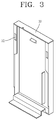
- FIG. 3 is a view illustrating a cable cover for protecting a breaker circuit of the ring main unit
- FIG. 4A is a schematic side view illustrating a state immediately before a cable cover is attached to a ring main unit
- FIG. 4B is a schematic side view illustrating a state in which the cable cover is attached to the ring main unit
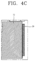
- FIG. 4C is a schematic side view illustrating a state in which the cable cover is attached to the ring main unit and then moved in a downward direction.
- a cable cover 30 is attached to or detached from a ring main unit 10 in the related art to protect each circuit.
- a holder 20 is provided within the ring main unit 10, and the cable cover 30 is inserted and fixed to the ring main unit 10 while the holder 20 is inserted into an engagement hole 31 formed on the cable cover 30.
- a mechanism for operation is provided in a breaker circuit or load break switch circuit, and thus an interlock device is provided to control the attachment and detachment of the cable cover 30 according to the state of the mechanism, but a mechanism does not exist at a side of a RISER circuit of the ring main unit 10, and thus the interlock device is not provided to additionally control the attachment and detachment of the cable cover 30.
- the cable cover 30 at a side of the RISER circuit may be detachable while the ring main unit 10 is conducting, thereby causing a problem in which safety accidents frequently occur for a user.
- a user should move the cable cover 30 in a vertical direction each time during the attachment and detachment of cable cover 30, thereby causing a problem of significantly reducing the ease of use.
- an impact may be applied to the ring main unit 10 during the attachment and detachment of the cable cover 30, thereby causing a problem of damaging components when used for a long period of time.
- the present disclosure is contrived to solve the foregoing problems, and an object of the present disclosure is to provide an interlock device of a ring main unit for controlling the attachment and detachment of a RISER circuit side cable cover provided in the ring main unit.
- an interlock device of a ring main unit attached to an inner frame of the ring main unit to control the attachment and detachment of a cable cover may include a fixed portion fixed to the inner frame; an upper shaft bar provided to be surrounded by an elastic member, and formed with an elastic member compression platform to be protruded on an outer circumferential surface thereof to compress the elastic member or release the compression through the elastic member compression platform while moving in a vertical direction in a state of passing through the fixed portion; and a lower shaft bar connected to the upper shaft bar in an interlocking manner at a lower side of the upper shaft bar to move in interlocking with the cable cover in a state that the cable cover is inserted thereinto to compress the elastic member or release the compression through the upper shaft bar.
- a movement prevention member may be provided between the upper shaft bar and the lower shaft bar.
- an insertion hole and a fixed member coupled to the insertion hole may be provided on a front surface of the movement prevention member, and the fixed member may be brought into contact with the inner frame to prevent the detachment of the cable cover.
- the fixed portion may include an upper plate formed with a through hole to move in a vertical direction through the upper shaft bar; a lateral plate extended in a downward direction from both ends of the upper plate; and a fixed plate extended from an end of the lateral plate in a lateral direction and formed with a fixed hole to fix the inner frame.
- the elastic member compression platform may have any one of a cylindrical shape, a rod shape, a cam shape, and a plate shape.
- a close contact groove may be formed at an upper portion of the cable cover, and the lower shaft bar may include a body portion; a close contact portion inserted into the close contact groove when coupled to the cable cover at an upper end of the body portion; and a connection platform extended to an upper side of the close contact portion and coupled to the movement prevention member.
- a radial directional length of the close contact portion may be formed to be shorter than that of the body portion.
- close contact groove and the close contact portion may have the same curvature.
- a plurality of protrusions may be formed on an outer circumferential surface of the fixed member to facilitate rotation.
- the interlock device may further include a support portion, one end of which is connected to the fixed portion, and the other end of which is allowed for the upper shaft bar to pass therethrough to support the movement of the upper shaft bar.
- the support portion may have a " ⁇ "-shape.
- a lock groove for locking a lock may be formed at a central portion of the movement prevention member.
- an interlock device of a ring main unit may allow a cable cover to be attached thereto or detached therefrom using a spring, thereby having an effect of facilitating the attachment and detachment of the cable cover through an elastic force of the spring.
- attachment and detachment of a cable cover may be carried out through a spring, thereby preventing an impact from being applied to the ring main unit during the attachment and detachment of the cable cover.
- a lock function may be provided using a lock, thereby having an effect of restricting an unauthorized person's access.
- a fixed member may be coupled thereto to restrict the detachment of the cable cover through the fixed member to allow a user to recheck whether or not the ring main unit is conducting and then detach the cable cover, thereby having an effect of preventing a safety accident in advance from occurring during the use thereof.
- FIG. 5 is a partially enlarged view illustrating a state in which an interlock device according to the present disclosure is attached to a ring main unit
- FIG. 6 is a perspective view illustrating a cable cover, the attachment and detachment of which is controlled through an interlock device according to the present disclosure
- FIG. 7 is a perspective view illustrating an interlock device according to the present disclosure
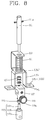
- FIG. 8 is an exploded perspective view illustrating an interlock device according to the present disclosure
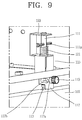
- FIG. 9 is another perspective view illustrating an interlock device according to the present disclosure.
- an interlock device 110 of a ring main unit is attached to an inner frame 101 of a ring main unit 100 to control the attachment and detachment of a RISER circuit side cable cover 103 in the ring main unit 100.
- the interlock device 110 may include an upper shaft bar 111, a fixed portion 115, and a lower shaft bar 113.
- the upper shaft bar 111 is made in a cylindrical shape, and formed to be surrounded by an elastic member 121 such as a spring.
- an elastic member compression platform 111 a is formed in a protruding manner on an outer circumferential surface thereof, and a lower surface of the elastic member compression platform 111 a is placed at an upper end of the elastic member 121 in a closely contacted state.
- the elastic member compression platform 111a compresses the elastic member 121 or releases the compression.
- the elastic member compression platform 111a may be formed in various shapes such as a cam shape, a cylindrical shape or a plate shape.
- the fixed portion 115 is fixed to allow the upper shaft bar 111 to move in a vertical direction therethrough.
- the fixed portion 115 may include an upper plate 115a, a lateral plate 115b, and a fixed plate 115c.
- the upper plate 115a is located in a horizontal direction to the inner frame 101, and a through hole (not shown) is formed to allow the upper shaft bar 111 to move therethrough, and the upper shaft bar 111 moves in a state of being inserted into the through hole.
- the lateral plate 115b is extended to a lower side of the upper plate 115a from both ends of the upper plate 115a
- the fixed plate 115c is extended from an end of the lateral plate 115b in a lateral direction and formed with a fixed hole 115c-1 to fix the inner frame 101, and a connection member (not shown) such as a rivet passes through the fixed hole 115c-1 and the inner frame 101 to allow the interlock device 110 to be fixed to the inner frame 101 through the fixed plate 115c.
- the fixed portion 115 may include a support portion 123 in a " ⁇ "-shape to support the movement of the upper shaft bar 111, an end of the support portion 123 is connected to the fixed portion 115, and the other end thereof is allowed for an upper portion of the upper shaft bar 111 to pass therethrough to support the movement of the upper shaft bar 111.
- the lower shaft bar 113 is connected to the upper shaft bar 111 in an interlocking manner at a lower side of the upper shaft bar 111, and the cable cover 103 moves in interlocking with the cable cover 103 in a state that the cable cover 103 is inserted thereinto to compress the elastic member 121 or release the compression through the upper shaft bar 111.
- a close contact groove 103a is formed at an upper end of the cable cover 103, and the lower shaft bar may include a body portion 113a, a close contact portion 113b, and a connection platform 113c.
- the body portion 113a is made in a cylindrical shape, the close contact portion 113b is protruded at an upper end of the body portion 113a and inserted into the close contact groove 103a when coupled to the cable cover 103.
- the close contact groove 103a and the close contact portion 113b are formed to have the same curvature, and when the close contact portion 113b is inserted into the close contact groove 103a, an outer circumferential surface of the close contact portion 113b is brought into contact with the close contact groove 103a.
- a radial directional length of the close contact portion 113b is formed to be shorter than that of the body portion 113a, when coupled to the cable cover 103, the body portion 113a is also moved according to the movement of the cable cover 103 while a predetermined portion of the body portion 113a is brought into contact with a lower surface of an upper end of the cable cover 103.
- connection platform 113c is extended to an upper side of the close contact portion 113b and inserted into a lower portion of the movement prevention member 117 which will be described below.
- the movement prevention member 117 for connecting the upper shaft bar 111 and the lower shaft bar 113 is further provided between the upper shaft bar 111 and the lower shaft bar 113.
- the movement prevention member 117 is connected between the upper shaft bar 111 and the lower shaft bar 113 to move the upper shaft bar 111 and the lower shaft bar 113 in an interlocking manner according to the movement of the cable cover 103.
- a lower end of the upper shaft bar 111 is inserted into an upper end of the movement prevention member 117 and connected thereto through a first fastening member 125, and an upper end of the lower shaft bar 113 is inserted into a lower end of the movement prevention member 117 and connected to thereto through a second fastening member 126, and thus the upper shaft bar 111 and the lower shaft bar 113 move in an interlocking manner through the movement prevention member 117.
- the upper shaft bar 111 connected to the lower shaft bar 113 through the movement prevention member 117 is also moved downward while at the same time moving the lower shaft bar 113, and the elastic member compression platform 111a compresses the elastic member 121 according to the movement of the upper shaft bar 111.
- the elastic member 121 presses the elastic member compression platform 111a while being restored to an original position through an elastic restoring force during the separation of the cable cover 103
- the upper shaft bar 111, the movement prevention member 117 and the lower shaft bar 113 move the cable cover 103 at the same time while moving upward to easily carry out the separation of the cable cover 103 without applying a large force, thereby preventing an impact from being applied to the ring main unit 100 during the separation of the cable cover 103 since a large force is not applied thereto.
- an insertion hole 117a is formed on a front surface of the movement prevention member 117, and when the cable cover 103 moves in a downward direction in a state that the close contact portion 113b is inserted into the close contact groove 103a, and the insertion hole 117a is placed at a lower side of the inner frame 101 while at the same time the movement prevention member 117 also moves in interlocking with the lower shaft bar 113.
- a lock groove 117b for locking a lock is further formed at a central portion of the movement prevention member 117 to restrict an unauthorized person's use.
- the fixed member 119 is inserted into the insertion hole 117a to restrict the movement of the cable cover 103, and a object protrusions 119a are formed on an outer circumferential surface of the fixed member 119, thereby facilitating rotation through the protrusions 119a when a user couples the fixed member 119 to the insertion hole 117a while rotating the fixed member 119.
- the cable cover 103 may be attached thereto or detached therefrom using a spring, thereby facilitating the attachment and detachment of the cable cover 103 through an elastic force of the spring.
- the attachment and detachment of the cable cover 103 may be carried out through a spring, thereby preventing an impact from being applied to the ring main unit 100 during the attachment and detachment of the cable cover 103.
- a lock function may be provided using a lock, thereby restricting an unauthorized person's access.
- the fixed member 119 may be coupled thereto to restrict the detachment of the cable cover 103 through the fixed member 119 to allow a user to recheck whether or not the ring main unit 100 is conducting and then detach the cable cover 103, thereby preventing a safety accident in advance from occurring during the use thereof.
Landscapes
- Engineering & Computer Science (AREA)
- Mechanical Engineering (AREA)
- Power Engineering (AREA)
- Details Of Connecting Devices For Male And Female Coupling (AREA)
- Flexible Shafts (AREA)
- Auxiliary Devices For Machine Tools (AREA)
- Driving Mechanisms And Operating Circuits Of Arc-Extinguishing High-Tension Switches (AREA)
- Patch Boards (AREA)
Abstract
Description
- The present invention relates to an interlock device of a ring main unit, and more particularly, to an interlock device of a ring main unit for controlling the attachment and detachment of a RISER circuit side cable cover provided in the ring main unit.
- In general, a ring main unit (RMU), as a device used to monitor, control and protect an electrical system used for receiving and distributing power sent from a switchboard to a customer, is configured with a collection including a breaker, a switchgear, a grounding and conductors, and the like within a structure sealed and insulated by SF6 gas.
- The ring main unit is provided with a CB circuit (breaker circuit), an LBS circuit (load break switch circuit), a fuse circuit, a RISER circuit, and the like within an enclosure, and a cable cover is attached thereto or detached therefrom to protect each circuit.
- On the other hand,
FIG. 1 is a perspective view illustrating a ring main unit in the related art, andFIG. 2 is a partially enlarged view illustrating a state in which a holder is provided in a ring main unit in the related art, andFIG. 3 is a view illustrating a cable cover for protecting a breaker circuit of the ring main unit, andFIG. 4A is a schematic side view illustrating a state immediately before a cable cover is attached to a ring main unit, andFIG. 4B is a schematic side view illustrating a state in which the cable cover is attached to the ring main unit, andFIG. 4C is a schematic side view illustrating a state in which the cable cover is attached to the ring main unit and then moved in a downward direction. - As illustrated in
FIGS. 1 through 3 , acable cover 30 is attached to or detached from a ringmain unit 10 in the related art to protect each circuit. - Here, a
holder 20 is provided within the ringmain unit 10, and thecable cover 30 is inserted and fixed to the ringmain unit 10 while theholder 20 is inserted into anengagement hole 31 formed on thecable cover 30. - In other words, as illustrated in
FIGS. 4A through 4C , when thecable cover 30 is inserted into the ringmain unit 10, theholder 20 is inserted into theengagement hole 31 formed on thecable cover 30, and when thecable cover 30 moves in a downward direction in a state of being inserted into theengagement hole 31, the separation of thecable cover 30 is prevented while an end of theholder 20 is placed at an upper side of theengagement hole 31. - On the other hand, a mechanism for operation is provided in a breaker circuit or load break switch circuit, and thus an interlock device is provided to control the attachment and detachment of the
cable cover 30 according to the state of the mechanism, but a mechanism does not exist at a side of a RISER circuit of the ringmain unit 10, and thus the interlock device is not provided to additionally control the attachment and detachment of thecable cover 30. - Accordingly, the cable cover 30 at a side of the RISER circuit may be detachable while the ring
main unit 10 is conducting, thereby causing a problem in which safety accidents frequently occur for a user. - Furthermore, a user should move the
cable cover 30 in a vertical direction each time during the attachment and detachment ofcable cover 30, thereby causing a problem of significantly reducing the ease of use. - In addition, an impact may be applied to the ring
main unit 10 during the attachment and detachment of thecable cover 30, thereby causing a problem of damaging components when used for a long period of time. - The present disclosure is contrived to solve the foregoing problems, and an object of the present disclosure is to provide an interlock device of a ring main unit for controlling the attachment and detachment of a RISER circuit side cable cover provided in the ring main unit.
- The foregoing object of the present disclosure may be accomplished by providing an interlock device of a ring main unit attached to an inner frame of the ring main unit to control the attachment and detachment of a cable cover, and the interlock device may include a fixed portion fixed to the inner frame; an upper shaft bar provided to be surrounded by an elastic member, and formed with an elastic member compression platform to be protruded on an outer circumferential surface thereof to compress the elastic member or release the compression through the elastic member compression platform while moving in a vertical direction in a state of passing through the fixed portion; and a lower shaft bar connected to the upper shaft bar in an interlocking manner at a lower side of the upper shaft bar to move in interlocking with the cable cover in a state that the cable cover is inserted thereinto to compress the elastic member or release the compression through the upper shaft bar.
- Furthermore, a movement prevention member may be provided between the upper shaft bar and the lower shaft bar.
- Furthermore, an insertion hole and a fixed member coupled to the insertion hole may be provided on a front surface of the movement prevention member, and the fixed member may be brought into contact with the inner frame to prevent the detachment of the cable cover.
- Furthermore, the fixed portion may include an upper plate formed with a through hole to move in a vertical direction through the upper shaft bar; a lateral plate extended in a downward direction from both ends of the upper plate; and a fixed plate extended from an end of the lateral plate in a lateral direction and formed with a fixed hole to fix the inner frame.
- Furthermore, the elastic member compression platform may have any one of a cylindrical shape, a rod shape, a cam shape, and a plate shape.
- Furthermore, a close contact groove may be formed at an upper portion of the cable cover, and the lower shaft bar may include a body portion; a close contact portion inserted into the close contact groove when coupled to the cable cover at an upper end of the body portion; and a connection platform extended to an upper side of the close contact portion and coupled to the movement prevention member.
- Furthermore, a radial directional length of the close contact portion may be formed to be shorter than that of the body portion.
- Furthermore, the close contact groove and the close contact portion may have the same curvature.
- Furthermore, a plurality of protrusions may be formed on an outer circumferential surface of the fixed member to facilitate rotation.
- Furthermore, the interlock device may further include a support portion, one end of which is connected to the fixed portion, and the other end of which is allowed for the upper shaft bar to pass therethrough to support the movement of the upper shaft bar.
- Furthermore, the support portion may have a "Π"-shape.
- Furthermore, a lock groove for locking a lock may be formed at a central portion of the movement prevention member.
- As described above, an interlock device of a ring main unit according to the present disclosure may allow a cable cover to be attached thereto or detached therefrom using a spring, thereby having an effect of facilitating the attachment and detachment of the cable cover through an elastic force of the spring.
- Furthermore, the attachment and detachment of a cable cover may be carried out through a spring, thereby preventing an impact from being applied to the ring main unit during the attachment and detachment of the cable cover.
- Furthermore, a lock function may be provided using a lock, thereby having an effect of restricting an unauthorized person's access.
- Furthermore, when a cable cover is attached thereto, a fixed member may be coupled thereto to restrict the detachment of the cable cover through the fixed member to allow a user to recheck whether or not the ring main unit is conducting and then detach the cable cover, thereby having an effect of preventing a safety accident in advance from occurring during the use thereof.
- The accompanying drawings, which are included to provide a further understanding of the invention and are incorporated in and constitute a part of this specification, illustrate embodiments of the invention and together with the description serve to explain the principles of the invention.
- In the drawings:
-
FIG. 1 is a perspective view illustrating a ring main unit in the related art; -
FIG. 2 is a partially enlarged view illustrating a state in which a holder is provided in a ring main unit in the related art; -
FIG. 3 is a perspective view illustrating a state in which an engagement hole is formed on a cable cover inserted into a ring main unit in the related art; -
FIG. 4A is a schematic side view illustrating a state immediately before a cable cover is inserted into a ring main unit; -
FIG. 4B is a schematic side view illustrating a state in which a holder provided in the ring main unit is inserted into an engagement hole of the cable cover; -
FIG. 4C is a schematic side view illustrating a state in which the cable cover is inserted into the ring main unit and then lowered in a downward direction; -
FIG. 5 is a partially enlarged view illustrating a state in which an interlock device according to the present disclosure is attached to a ring main unit; -
FIG. 6 is a perspective view illustrating a cable cover, the attachment and detachment of which is controlled through an interlock device according to the present disclosure; -
FIG. 7 is a perspective view illustrating an interlock device according to the present disclosure; -
FIG. 8 is an exploded perspective view illustrating an interlock device according to the present disclosure; and -
FIG. 9 is another perspective view illustrating an interlock device according to the present disclosure. - Hereinafter, an interlock device of a ring main unit according to an embodiment of the present disclosure will be described in detail with reference to the accompanying drawings.
-
FIG. 5 is a partially enlarged view illustrating a state in which an interlock device according to the present disclosure is attached to a ring main unit, andFIG. 6 is a perspective view illustrating a cable cover, the attachment and detachment of which is controlled through an interlock device according to the present disclosure, andFIG. 7 is a perspective view illustrating an interlock device according to the present disclosure, andFIG. 8 is an exploded perspective view illustrating an interlock device according to the present disclosure, andFIG. 9 is another perspective view illustrating an interlock device according to the present disclosure. - As illustrated in
FIG. 5 through 8 , aninterlock device 110 of a ring main unit according to the present disclosure is attached to aninner frame 101 of a ringmain unit 100 to control the attachment and detachment of a RISER circuitside cable cover 103 in the ringmain unit 100. - Here, the
interlock device 110 may include anupper shaft bar 111, a fixedportion 115, and alower shaft bar 113. - The
upper shaft bar 111 is made in a cylindrical shape, and formed to be surrounded by anelastic member 121 such as a spring. - Furthermore, an elastic
member compression platform 111 a is formed in a protruding manner on an outer circumferential surface thereof, and a lower surface of the elasticmember compression platform 111 a is placed at an upper end of theelastic member 121 in a closely contacted state. - Accordingly, when the
upper shaft bar 111 moves, the elasticmember compression platform 111a compresses theelastic member 121 or releases the compression. - Here, the elastic
member compression platform 111a may be formed in various shapes such as a cam shape, a cylindrical shape or a plate shape. - The
fixed portion 115 is fixed to allow theupper shaft bar 111 to move in a vertical direction therethrough. - Here, the
fixed portion 115 may include anupper plate 115a, alateral plate 115b, and afixed plate 115c. - The
upper plate 115a is located in a horizontal direction to theinner frame 101, and a through hole (not shown) is formed to allow theupper shaft bar 111 to move therethrough, and theupper shaft bar 111 moves in a state of being inserted into the through hole. - The
lateral plate 115b is extended to a lower side of theupper plate 115a from both ends of theupper plate 115a, and the fixedplate 115c is extended from an end of thelateral plate 115b in a lateral direction and formed with afixed hole 115c-1 to fix theinner frame 101, and a connection member (not shown) such as a rivet passes through the fixedhole 115c-1 and theinner frame 101 to allow theinterlock device 110 to be fixed to theinner frame 101 through the fixedplate 115c. - In addition, the fixed
portion 115 may include asupport portion 123 in a "Π"-shape to support the movement of theupper shaft bar 111, an end of thesupport portion 123 is connected to the fixedportion 115, and the other end thereof is allowed for an upper portion of theupper shaft bar 111 to pass therethrough to support the movement of theupper shaft bar 111. - The
lower shaft bar 113 is connected to theupper shaft bar 111 in an interlocking manner at a lower side of theupper shaft bar 111, and thecable cover 103 moves in interlocking with thecable cover 103 in a state that thecable cover 103 is inserted thereinto to compress theelastic member 121 or release the compression through theupper shaft bar 111. - Here, a
close contact groove 103a is formed at an upper end of thecable cover 103, and the lower shaft bar may include a body portion 113a, a close contact portion 113b, and aconnection platform 113c. - The body portion 113a is made in a cylindrical shape, the close contact portion 113b is protruded at an upper end of the body portion 113a and inserted into the
close contact groove 103a when coupled to thecable cover 103. - Here, the
close contact groove 103a and the close contact portion 113b are formed to have the same curvature, and when the close contact portion 113b is inserted into theclose contact groove 103a, an outer circumferential surface of the close contact portion 113b is brought into contact with theclose contact groove 103a. - Furthermore, a radial directional length of the close contact portion 113b is formed to be shorter than that of the body portion 113a, when coupled to the
cable cover 103, the body portion 113a is also moved according to the movement of thecable cover 103 while a predetermined portion of the body portion 113a is brought into contact with a lower surface of an upper end of thecable cover 103. - The
connection platform 113c is extended to an upper side of the close contact portion 113b and inserted into a lower portion of themovement prevention member 117 which will be described below. - On the other hand, the
movement prevention member 117 for connecting theupper shaft bar 111 and thelower shaft bar 113 is further provided between theupper shaft bar 111 and thelower shaft bar 113. - The
movement prevention member 117 is connected between theupper shaft bar 111 and thelower shaft bar 113 to move theupper shaft bar 111 and thelower shaft bar 113 in an interlocking manner according to the movement of thecable cover 103. - In other words, a lower end of the
upper shaft bar 111 is inserted into an upper end of themovement prevention member 117 and connected thereto through afirst fastening member 125, and an upper end of thelower shaft bar 113 is inserted into a lower end of themovement prevention member 117 and connected to thereto through asecond fastening member 126, and thus theupper shaft bar 111 and thelower shaft bar 113 move in an interlocking manner through themovement prevention member 117. - Accordingly, when moved in a state that the
cable cover 103 is inserted into thelower shaft bar 113, theupper shaft bar 111 connected to thelower shaft bar 113 through themovement prevention member 117 is also moved downward while at the same time moving thelower shaft bar 113, and the elasticmember compression platform 111a compresses theelastic member 121 according to the movement of theupper shaft bar 111. - Then, when the
elastic member 121 presses the elasticmember compression platform 111a while being restored to an original position through an elastic restoring force during the separation of thecable cover 103, theupper shaft bar 111, themovement prevention member 117 and thelower shaft bar 113 move thecable cover 103 at the same time while moving upward to easily carry out the separation of thecable cover 103 without applying a large force, thereby preventing an impact from being applied to the ringmain unit 100 during the separation of thecable cover 103 since a large force is not applied thereto. - Furthermore, as illustrated in
FIG. 9 , aninsertion hole 117a is formed on a front surface of themovement prevention member 117, and when thecable cover 103 moves in a downward direction in a state that the close contact portion 113b is inserted into theclose contact groove 103a, and theinsertion hole 117a is placed at a lower side of theinner frame 101 while at the same time themovement prevention member 117 also moves in interlocking with thelower shaft bar 113. - At this time, when the fixed
member 119 is inserted into theinsertion hole 117a, an upper end of the fixedmember 119 is closely contacted with a lower end of theinner frame 101 to restrict the movement of theinner frame 101 in an upward direction, thereby preventing the detachment of thecable cover 103. - In addition, a
lock groove 117b for locking a lock is further formed at a central portion of themovement prevention member 117 to restrict an unauthorized person's use. - On the other hand, the fixed
member 119 is inserted into theinsertion hole 117a to restrict the movement of thecable cover 103, and aobject protrusions 119a are formed on an outer circumferential surface of the fixedmember 119, thereby facilitating rotation through theprotrusions 119a when a user couples the fixedmember 119 to theinsertion hole 117a while rotating thefixed member 119. - In case of the present disclosure having the foregoing configuration, the
cable cover 103 may be attached thereto or detached therefrom using a spring, thereby facilitating the attachment and detachment of thecable cover 103 through an elastic force of the spring. - Furthermore, the attachment and detachment of the
cable cover 103 may be carried out through a spring, thereby preventing an impact from being applied to the ringmain unit 100 during the attachment and detachment of thecable cover 103. - Furthermore, a lock function may be provided using a lock, thereby restricting an unauthorized person's access.
- Furthermore, when the
cable cover 103 is attached thereto, the fixedmember 119 may be coupled thereto to restrict the detachment of thecable cover 103 through the fixedmember 119 to allow a user to recheck whether or not the ringmain unit 100 is conducting and then detach thecable cover 103, thereby preventing a safety accident in advance from occurring during the use thereof. - Though a preferred embodiment of the present invention has been described in the above, it will be apparent to those skilled in the art that various alternatives, changes and equivalents can be used for the present disclosure and the above embodiment is modified in an appropriate manner and applied thereto in the same manner. Accordingly, the disclosure is not intended to limit the scope of the invention as defined by the limitation of the following claims.
Claims (12)
- An interlock device of a ring main unit attached to an inner frame (101) of the ring main unit (100) to control the attachment and detachment of a cable cover (103), characterized in that the interlock device comprises:a fixed portion (115) fixed to the inner frame (101);an upper shaft bar (111) provided to be surrounded by an elastic member (121), and formed with an elastic member compression platform (111a) to be protruded on an outer circumferential surface thereof to compress the elastic member (121) or release the compression through the elastic member compression platform (111a) while moving in a vertical direction in a state of passing through the fixed portion (115); anda lower shaft bar (113) connected to the upper shaft bar (111) in an interlocking manner at a lower side of the upper shaft bar (111) to move in interlocking with the cable cover (103) in a state that the cable cover (103) is inserted thereinto to compress the elastic member (121) or release the compression through the upper shaft bar (111).
- The interlock device of 1, wherein a movement prevention member (117) is provided between the upper shaft bar (111) and the lower shaft bar (113).
- The interlock device of 2, wherein an insertion hole (117a) and a fixed member (119) coupled to the insertion hole (117a) are provided on a front surface of the movement prevention member (117), and
the fixed member (119) is brought into contact with the inner frame (101) to prevent the detachment of the cable cover (103). - The interlock device of 1, wherein the fixed portion (115) comprises:an upper plate (115a) formed with a through hole to move in a vertical direction through the upper shaft bar (111);a lateral plate (115b) extended in a downward direction from both ends of the upper plate (115a); anda fixed plate (115c) extended from an end of the lateral plate (115b) in a lateral direction and formed with a fixed hole (115c-1) to fix the inner frame (101).
- The interlock device of 1, wherein the elastic member compression platform (111 a) has any one of a cylindrical shape, a rod shape, a cam shape, and a plate shape.
- The interlock device of 1, wherein a close contact groove (103a) is formed at an upper portion of the cable cover (103), and
the lower shaft bar (113) comprises:a body portion (113a);a close contact portion(113b) inserted into the close contact groove (103a) when coupled to the cable cover (103) at an upper end of the body portion (113a); anda connection platform (113c) extended to an upper side of the close contact portion (113b) and coupled to the movement prevention member (117). - The interlock device of 6, wherein a radial directional length of the close contact portion (113b) is formed to be shorter than that of the body portion (113a).
- The interlock device of 6, wherein the close contact groove (103a) and the close contact portion (113b) have the same curvature.
- The interlock device of 2, wherein a plurality of protrusions (119a) are formed on an outer circumferential surface of the fixed member (119) to facilitate rotation.
- The interlock device of 1, further comprising:a support portion (123), one end of which is connected to the fixed portion (115), and the other end of which is allowed for the upper shaft bar (111) to pass therethrough to support the movement of the upper shaft bar (111).
- The interlock device of 10, wherein the support portion (123) has a "Π"-shape.
- The interlock device of 2, wherein a lock groove (117b) for locking a lock is formed at a central portion of the movement prevention member (117).
Applications Claiming Priority (1)
| Application Number | Priority Date | Filing Date | Title |
|---|---|---|---|
| KR2020150004744U KR200482521Y1 (en) | 2015-07-14 | 2015-07-14 | Interlock device of ring main unit |
Publications (2)
| Publication Number | Publication Date |
|---|---|
| EP3118875A1 true EP3118875A1 (en) | 2017-01-18 |
| EP3118875B1 EP3118875B1 (en) | 2020-02-26 |
Family
ID=56684436
Family Applications (1)
| Application Number | Title | Priority Date | Filing Date |
|---|---|---|---|
| EP16176915.3A Active EP3118875B1 (en) | 2015-07-14 | 2016-06-29 | Ring main unit with an interlock device |
Country Status (6)
| Country | Link |
|---|---|
| US (1) | US10526826B2 (en) |
| EP (1) | EP3118875B1 (en) |
| JP (1) | JP6280165B2 (en) |
| KR (1) | KR200482521Y1 (en) |
| CN (1) | CN106356755B (en) |
| ES (1) | ES2789298T3 (en) |
Cited By (2)
| Publication number | Priority date | Publication date | Assignee | Title |
|---|---|---|---|---|
| CN109412063A (en) * | 2017-08-16 | 2019-03-01 | 天津平高智能电气有限公司 | Breaker chamber interlock |
| US20220252215A1 (en) * | 2019-01-22 | 2022-08-11 | Core-Arms, LLC | Mounting System, Devices, Methods and Uses Thereof |
Families Citing this family (5)
| Publication number | Priority date | Publication date | Assignee | Title |
|---|---|---|---|---|
| EP3324443B1 (en) * | 2016-11-17 | 2019-09-11 | Fuji Electric Co., Ltd. | Semiconductor device |
| CN110676088A (en) * | 2019-11-13 | 2020-01-10 | 南京开关厂有限公司 | Aerify cabinet lower door interlock |
| CN112421403A (en) * | 2020-10-28 | 2021-02-26 | 广东电网有限责任公司 | Ring main unit |
| CN112735873A (en) * | 2020-12-29 | 2021-04-30 | 北京合锐清合电气有限公司 | Interlocking device of back door of bypass node type PT cabinet |
| US20250127301A1 (en) * | 2023-10-24 | 2025-04-24 | Vertiv Corporation | Shelf safety pin for cabinet |
Citations (3)
| Publication number | Priority date | Publication date | Assignee | Title |
|---|---|---|---|---|
| CN202353077U (en) * | 2011-12-05 | 2012-07-25 | 泰豪科技(深圳)电力技术有限公司 | Ring main unit and interlocking device thereof |
| CN202840331U (en) * | 2012-08-28 | 2013-03-27 | 泰豪科技(深圳)电力技术有限公司 | Interlocking device and ring main unit using interlocking device |
| CN203552983U (en) * | 2013-10-15 | 2014-04-16 | 施耐德电器工业公司 | nterlock grounding switch operation aperture and interlocking device of cable chamber room |
Family Cites Families (36)
| Publication number | Priority date | Publication date | Assignee | Title |
|---|---|---|---|---|
| US195223A (en) * | 1877-09-18 | Improvement in fasteners for meeting-rails of sashes | ||
| US2831734A (en) * | 1956-06-19 | 1958-04-22 | Carmic Mfg Co Inc | Scaffold connector device |
| US3233932A (en) * | 1963-10-15 | 1966-02-08 | Warren Ind Inc | Spring bolt |
| US3889993A (en) * | 1972-02-29 | 1975-06-17 | William L Bright | Safety lock for enclosures |
| US4138150A (en) * | 1975-10-01 | 1979-02-06 | Bills Marius W | Window lock |
| US4161804A (en) * | 1977-12-21 | 1979-07-24 | Rixson-Firemark, Inc. | Heat-actuated door latch |
| JPS5587112U (en) | 1978-12-08 | 1980-06-16 | ||
| NL8204919A (en) * | 1982-12-21 | 1984-07-16 | Verhoog Handel | LOCKING ASSEMBLY FOR A DOOR OR WINDOW. |
| US4699406A (en) * | 1986-01-23 | 1987-10-13 | Swanson Jr Chester | Automatic bolt lock |
| US4793438A (en) * | 1986-09-16 | 1988-12-27 | Perry Eugene D | Scaffold latch means |
| JPS6358439U (en) | 1986-10-02 | 1988-04-19 | ||
| JPH0313680A (en) | 1989-06-07 | 1991-01-22 | Fujitsu Ltd | Lock structure for door |
| US4997218A (en) * | 1990-01-22 | 1991-03-05 | The United States Of America As Represented By The Secretary Of The Army | Pin lock mechanism with bias change feature |
| JP2669098B2 (en) * | 1990-03-19 | 1997-10-27 | 富士電機株式会社 | Closed switchboard |
| US5104163A (en) * | 1991-08-09 | 1992-04-14 | Palmer Jr Clem L | Double self-latching, double-locking gate latch mechanism |
| US5390761A (en) * | 1993-09-21 | 1995-02-21 | Perry; Eugene D. | Latch for scaffolding |
| KR19990003422A (en) | 1997-06-25 | 1999-01-15 | 윤종용 | Air conditioner with outlet door |
| US6126211A (en) * | 1998-10-01 | 2000-10-03 | Dominquez; Edward | Slidable deadbolt security device for sliding doors and windows enabling selective locking thereof in closed or partially open position |
| US6095574A (en) * | 1999-06-01 | 2000-08-01 | Hewlett-Packard Company | Computer enclosure locking mechanism |
| KR200214270Y1 (en) | 2000-06-21 | 2001-02-15 | 엘지산전주식회사 | Switch board |
| JP4820021B2 (en) * | 2001-06-29 | 2011-11-24 | 立川ブラインド工業株式会社 | Roller blind screen guide device |
| JP4300451B2 (en) | 2002-04-16 | 2009-07-22 | 日本制禦機器株式会社 | Enclosure interlock mechanism |
| KR100557496B1 (en) * | 2004-07-13 | 2006-03-07 | 엘에스산전 주식회사 | Main switch feeder for high voltage breaker |
| KR100802093B1 (en) | 2006-09-19 | 2008-02-12 | (주)제일피앤피 | Cover device for switchboard |
| KR100894162B1 (en) | 2007-11-01 | 2009-04-22 | 한국단자공업 주식회사 | Cover coupling structure of box |
| KR100995277B1 (en) | 2008-06-23 | 2010-11-19 | 한국단자공업 주식회사 | Cover coupling device of box |
| KR100970274B1 (en) | 2008-06-24 | 2010-07-16 | 한국단자공업 주식회사 | Cover coupling device of box |
| KR101087511B1 (en) * | 2009-05-21 | 2011-11-29 | 엘에스산전 주식회사 | Entry and exit interlock device of the breaker |
| CN201498907U (en) * | 2009-08-13 | 2010-06-02 | 常熟开关制造有限公司(原常熟开关厂) | Circuit breaker interlocking device |
| JP2012115025A (en) | 2010-11-24 | 2012-06-14 | Mitsubishi Electric Corp | Switchgear |
| US8777279B2 (en) * | 2011-11-22 | 2014-07-15 | Multilink, Inc. | Container cover/door with high security locking system |
| KR101306347B1 (en) | 2011-12-09 | 2013-09-09 | (주) 디지털파워 | Fixed case for load center and earthquake-proof load center |
| KR101513204B1 (en) * | 2013-05-13 | 2015-04-17 | 엘에스산전 주식회사 | Switchgear having door interlock device |
| KR101522265B1 (en) * | 2013-10-16 | 2015-05-21 | 엘에스산전 주식회사 | Voltage transformer room door interlock device of panel for vacuum circuit breaker |
| CN104638538A (en) * | 2013-11-12 | 2015-05-20 | 国家电网公司 | Metering cabinet |
| CN203826789U (en) * | 2014-05-07 | 2014-09-10 | 江苏长宁电力科技有限公司 | Interlocking mechanism of high-voltage switch cabinet |
-
2015
- 2015-07-14 KR KR2020150004744U patent/KR200482521Y1/en not_active Expired - Fee Related
-
2016
- 2016-06-29 EP EP16176915.3A patent/EP3118875B1/en active Active
- 2016-06-29 ES ES16176915T patent/ES2789298T3/en active Active
- 2016-07-12 CN CN201610547495.9A patent/CN106356755B/en not_active Expired - Fee Related
- 2016-07-13 JP JP2016138356A patent/JP6280165B2/en not_active Expired - Fee Related
- 2016-07-13 US US15/209,577 patent/US10526826B2/en not_active Expired - Fee Related
Patent Citations (3)
| Publication number | Priority date | Publication date | Assignee | Title |
|---|---|---|---|---|
| CN202353077U (en) * | 2011-12-05 | 2012-07-25 | 泰豪科技(深圳)电力技术有限公司 | Ring main unit and interlocking device thereof |
| CN202840331U (en) * | 2012-08-28 | 2013-03-27 | 泰豪科技(深圳)电力技术有限公司 | Interlocking device and ring main unit using interlocking device |
| CN203552983U (en) * | 2013-10-15 | 2014-04-16 | 施耐德电器工业公司 | nterlock grounding switch operation aperture and interlocking device of cable chamber room |
Cited By (3)
| Publication number | Priority date | Publication date | Assignee | Title |
|---|---|---|---|---|
| CN109412063A (en) * | 2017-08-16 | 2019-03-01 | 天津平高智能电气有限公司 | Breaker chamber interlock |
| US20220252215A1 (en) * | 2019-01-22 | 2022-08-11 | Core-Arms, LLC | Mounting System, Devices, Methods and Uses Thereof |
| US12372196B2 (en) * | 2019-01-22 | 2025-07-29 | Core-Arms, LLC | Mounting system, devices, methods and uses thereof |
Also Published As
| Publication number | Publication date |
|---|---|
| EP3118875B1 (en) | 2020-02-26 |
| CN106356755B (en) | 2018-08-31 |
| US10526826B2 (en) | 2020-01-07 |
| CN106356755A (en) | 2017-01-25 |
| KR200482521Y1 (en) | 2017-02-03 |
| JP2017022986A (en) | 2017-01-26 |
| ES2789298T3 (en) | 2020-10-26 |
| US20170016256A1 (en) | 2017-01-19 |
| KR20170000321U (en) | 2017-01-24 |
| JP6280165B2 (en) | 2018-02-14 |
Similar Documents
| Publication | Publication Date | Title |
|---|---|---|
| EP3118875B1 (en) | Ring main unit with an interlock device | |
| US9825439B2 (en) | Withdrawable interlock device of vacuum circuit breaker | |
| TWI469176B (en) | Lead-out circuit breaker and switchboard | |
| CN105305278B (en) | The shutter of resistance to electric arc | |
| JP3514290B2 (en) | Circuit breaker | |
| CN105374591A (en) | Fuse-type isolation switch | |
| US2727966A (en) | Circuit breakers | |
| CN105742965A (en) | Switchboard With Position-Indicating Apparatus | |
| KR102320722B1 (en) | Device For Repairing Overhead Distribution Line | |
| CN102568878B (en) | Shock preventing mechanism having buffering stress-alleviating function | |
| KR101650698B1 (en) | Interlock device of door and switch-gear having the same | |
| EP3048624A1 (en) | Interlock device of ring main unit | |
| CN215815762U (en) | Small circuit breaker with anti-touch structure | |
| JP6245673B1 (en) | Power line connection device | |
| CN107017140B (en) | Fuse, fuse assembly and circuit with fuse | |
| CN205081026U (en) | Fuse type isolation switch | |
| KR101129243B1 (en) | Apparatus for covering switch and method of operating thereof | |
| US20170162356A1 (en) | Electrical switching apparatus and strain relief assembly therefor | |
| CN211929417U (en) | Double-breakpoint operating mechanism capable of controlling actions inside and outside and circuit breaker | |
| KR20180064015A (en) | Circuit breaker | |
| CN208903948U (en) | A kind of wiring baffle for breaker | |
| KR20250111556A (en) | Upper cover for indirect live cut out switch | |
| CN104362013B (en) | Control and protective switching device isolation module | |
| EP1261004B1 (en) | Connection device for a residual-current module | |
| JP2013179012A (en) | Fuse holder |
Legal Events
| Date | Code | Title | Description |
|---|---|---|---|
| PUAI | Public reference made under article 153(3) epc to a published international application that has entered the european phase |
Free format text: ORIGINAL CODE: 0009012 |
|
| STAA | Information on the status of an ep patent application or granted ep patent |
Free format text: STATUS: THE APPLICATION HAS BEEN PUBLISHED |
|
| AK | Designated contracting states |
Kind code of ref document: A1 Designated state(s): AL AT BE BG CH CY CZ DE DK EE ES FI FR GB GR HR HU IE IS IT LI LT LU LV MC MK MT NL NO PL PT RO RS SE SI SK SM TR |
|
| AX | Request for extension of the european patent |
Extension state: BA ME |
|
| STAA | Information on the status of an ep patent application or granted ep patent |
Free format text: STATUS: REQUEST FOR EXAMINATION WAS MADE |
|
| 17P | Request for examination filed |
Effective date: 20170711 |
|
| RBV | Designated contracting states (corrected) |
Designated state(s): AL AT BE BG CH CY CZ DE DK EE ES FI FR GB GR HR HU IE IS IT LI LT LU LV MC MK MT NL NO PL PT RO RS SE SI SK SM TR |
|
| STAA | Information on the status of an ep patent application or granted ep patent |
Free format text: STATUS: EXAMINATION IS IN PROGRESS |
|
| 17Q | First examination report despatched |
Effective date: 20190215 |
|
| RIC1 | Information provided on ipc code assigned before grant |
Ipc: H02B 7/06 20060101ALN20190821BHEP Ipc: H01H 9/22 20060101AFI20190821BHEP Ipc: H02B 13/02 20060101ALN20190821BHEP |
|
| GRAP | Despatch of communication of intention to grant a patent |
Free format text: ORIGINAL CODE: EPIDOSNIGR1 |
|
| STAA | Information on the status of an ep patent application or granted ep patent |
Free format text: STATUS: GRANT OF PATENT IS INTENDED |
|
| RIC1 | Information provided on ipc code assigned before grant |
Ipc: H01H 9/22 20060101AFI20190919BHEP Ipc: H02B 13/02 20060101ALN20190919BHEP Ipc: H02B 7/06 20060101ALN20190919BHEP |
|
| INTG | Intention to grant announced |
Effective date: 20191011 |
|
| GRAS | Grant fee paid |
Free format text: ORIGINAL CODE: EPIDOSNIGR3 |
|
| GRAA | (expected) grant |
Free format text: ORIGINAL CODE: 0009210 |
|
| STAA | Information on the status of an ep patent application or granted ep patent |
Free format text: STATUS: THE PATENT HAS BEEN GRANTED |
|
| AK | Designated contracting states |
Kind code of ref document: B1 Designated state(s): AL AT BE BG CH CY CZ DE DK EE ES FI FR GB GR HR HU IE IS IT LI LT LU LV MC MK MT NL NO PL PT RO RS SE SI SK SM TR |
|
| REG | Reference to a national code |
Ref country code: GB Ref legal event code: FG4D |
|
| REG | Reference to a national code |
Ref country code: CH Ref legal event code: EP |
|
| REG | Reference to a national code |
Ref country code: DE Ref legal event code: R096 Ref document number: 602016030431 Country of ref document: DE |
|
| REG | Reference to a national code |
Ref country code: AT Ref legal event code: REF Ref document number: 1238645 Country of ref document: AT Kind code of ref document: T Effective date: 20200315 |
|
| REG | Reference to a national code |
Ref country code: IE Ref legal event code: FG4D |
|
| PG25 | Lapsed in a contracting state [announced via postgrant information from national office to epo] |
Ref country code: NO Free format text: LAPSE BECAUSE OF FAILURE TO SUBMIT A TRANSLATION OF THE DESCRIPTION OR TO PAY THE FEE WITHIN THE PRESCRIBED TIME-LIMIT Effective date: 20200526 Ref country code: FI Free format text: LAPSE BECAUSE OF FAILURE TO SUBMIT A TRANSLATION OF THE DESCRIPTION OR TO PAY THE FEE WITHIN THE PRESCRIBED TIME-LIMIT Effective date: 20200226 Ref country code: RS Free format text: LAPSE BECAUSE OF FAILURE TO SUBMIT A TRANSLATION OF THE DESCRIPTION OR TO PAY THE FEE WITHIN THE PRESCRIBED TIME-LIMIT Effective date: 20200226 |
|
| PGFP | Annual fee paid to national office [announced via postgrant information from national office to epo] |
Ref country code: DE Payment date: 20200506 Year of fee payment: 5 Ref country code: FR Payment date: 20200511 Year of fee payment: 5 |
|
| REG | Reference to a national code |
Ref country code: NL Ref legal event code: MP Effective date: 20200226 |
|
| REG | Reference to a national code |
Ref country code: LT Ref legal event code: MG4D |
|
| PG25 | Lapsed in a contracting state [announced via postgrant information from national office to epo] |
Ref country code: GR Free format text: LAPSE BECAUSE OF FAILURE TO SUBMIT A TRANSLATION OF THE DESCRIPTION OR TO PAY THE FEE WITHIN THE PRESCRIBED TIME-LIMIT Effective date: 20200527 Ref country code: IS Free format text: LAPSE BECAUSE OF FAILURE TO SUBMIT A TRANSLATION OF THE DESCRIPTION OR TO PAY THE FEE WITHIN THE PRESCRIBED TIME-LIMIT Effective date: 20200626 Ref country code: SE Free format text: LAPSE BECAUSE OF FAILURE TO SUBMIT A TRANSLATION OF THE DESCRIPTION OR TO PAY THE FEE WITHIN THE PRESCRIBED TIME-LIMIT Effective date: 20200226 Ref country code: LV Free format text: LAPSE BECAUSE OF FAILURE TO SUBMIT A TRANSLATION OF THE DESCRIPTION OR TO PAY THE FEE WITHIN THE PRESCRIBED TIME-LIMIT Effective date: 20200226 Ref country code: HR Free format text: LAPSE BECAUSE OF FAILURE TO SUBMIT A TRANSLATION OF THE DESCRIPTION OR TO PAY THE FEE WITHIN THE PRESCRIBED TIME-LIMIT Effective date: 20200226 Ref country code: BG Free format text: LAPSE BECAUSE OF FAILURE TO SUBMIT A TRANSLATION OF THE DESCRIPTION OR TO PAY THE FEE WITHIN THE PRESCRIBED TIME-LIMIT Effective date: 20200526 |
|
| PGFP | Annual fee paid to national office [announced via postgrant information from national office to epo] |
Ref country code: IT Payment date: 20200623 Year of fee payment: 5 Ref country code: GB Payment date: 20200511 Year of fee payment: 5 |
|
| PG25 | Lapsed in a contracting state [announced via postgrant information from national office to epo] |
Ref country code: NL Free format text: LAPSE BECAUSE OF FAILURE TO SUBMIT A TRANSLATION OF THE DESCRIPTION OR TO PAY THE FEE WITHIN THE PRESCRIBED TIME-LIMIT Effective date: 20200226 |
|
| REG | Reference to a national code |
Ref country code: ES Ref legal event code: FG2A Ref document number: 2789298 Country of ref document: ES Kind code of ref document: T3 Effective date: 20201026 |
|
| PG25 | Lapsed in a contracting state [announced via postgrant information from national office to epo] |
Ref country code: EE Free format text: LAPSE BECAUSE OF FAILURE TO SUBMIT A TRANSLATION OF THE DESCRIPTION OR TO PAY THE FEE WITHIN THE PRESCRIBED TIME-LIMIT Effective date: 20200226 Ref country code: LT Free format text: LAPSE BECAUSE OF FAILURE TO SUBMIT A TRANSLATION OF THE DESCRIPTION OR TO PAY THE FEE WITHIN THE PRESCRIBED TIME-LIMIT Effective date: 20200226 Ref country code: SK Free format text: LAPSE BECAUSE OF FAILURE TO SUBMIT A TRANSLATION OF THE DESCRIPTION OR TO PAY THE FEE WITHIN THE PRESCRIBED TIME-LIMIT Effective date: 20200226 Ref country code: PT Free format text: LAPSE BECAUSE OF FAILURE TO SUBMIT A TRANSLATION OF THE DESCRIPTION OR TO PAY THE FEE WITHIN THE PRESCRIBED TIME-LIMIT Effective date: 20200719 Ref country code: CZ Free format text: LAPSE BECAUSE OF FAILURE TO SUBMIT A TRANSLATION OF THE DESCRIPTION OR TO PAY THE FEE WITHIN THE PRESCRIBED TIME-LIMIT Effective date: 20200226 Ref country code: RO Free format text: LAPSE BECAUSE OF FAILURE TO SUBMIT A TRANSLATION OF THE DESCRIPTION OR TO PAY THE FEE WITHIN THE PRESCRIBED TIME-LIMIT Effective date: 20200226 Ref country code: DK Free format text: LAPSE BECAUSE OF FAILURE TO SUBMIT A TRANSLATION OF THE DESCRIPTION OR TO PAY THE FEE WITHIN THE PRESCRIBED TIME-LIMIT Effective date: 20200226 Ref country code: SM Free format text: LAPSE BECAUSE OF FAILURE TO SUBMIT A TRANSLATION OF THE DESCRIPTION OR TO PAY THE FEE WITHIN THE PRESCRIBED TIME-LIMIT Effective date: 20200226 |
|
| PGFP | Annual fee paid to national office [announced via postgrant information from national office to epo] |
Ref country code: ES Payment date: 20200709 Year of fee payment: 5 |
|
| REG | Reference to a national code |
Ref country code: AT Ref legal event code: MK05 Ref document number: 1238645 Country of ref document: AT Kind code of ref document: T Effective date: 20200226 |
|
| REG | Reference to a national code |
Ref country code: DE Ref legal event code: R097 Ref document number: 602016030431 Country of ref document: DE |
|
| PLBE | No opposition filed within time limit |
Free format text: ORIGINAL CODE: 0009261 |
|
| STAA | Information on the status of an ep patent application or granted ep patent |
Free format text: STATUS: NO OPPOSITION FILED WITHIN TIME LIMIT |
|
| PG25 | Lapsed in a contracting state [announced via postgrant information from national office to epo] |
Ref country code: MC Free format text: LAPSE BECAUSE OF FAILURE TO SUBMIT A TRANSLATION OF THE DESCRIPTION OR TO PAY THE FEE WITHIN THE PRESCRIBED TIME-LIMIT Effective date: 20200226 Ref country code: AT Free format text: LAPSE BECAUSE OF FAILURE TO SUBMIT A TRANSLATION OF THE DESCRIPTION OR TO PAY THE FEE WITHIN THE PRESCRIBED TIME-LIMIT Effective date: 20200226 |
|
| REG | Reference to a national code |
Ref country code: CH Ref legal event code: PL |
|
| 26N | No opposition filed |
Effective date: 20201127 |
|
| PG25 | Lapsed in a contracting state [announced via postgrant information from national office to epo] |
Ref country code: SI Free format text: LAPSE BECAUSE OF FAILURE TO SUBMIT A TRANSLATION OF THE DESCRIPTION OR TO PAY THE FEE WITHIN THE PRESCRIBED TIME-LIMIT Effective date: 20200226 Ref country code: PL Free format text: LAPSE BECAUSE OF FAILURE TO SUBMIT A TRANSLATION OF THE DESCRIPTION OR TO PAY THE FEE WITHIN THE PRESCRIBED TIME-LIMIT Effective date: 20200226 |
|
| PG25 | Lapsed in a contracting state [announced via postgrant information from national office to epo] |
Ref country code: LU Free format text: LAPSE BECAUSE OF NON-PAYMENT OF DUE FEES Effective date: 20200629 |
|
| REG | Reference to a national code |
Ref country code: BE Ref legal event code: MM Effective date: 20200630 |
|
| PG25 | Lapsed in a contracting state [announced via postgrant information from national office to epo] |
Ref country code: IE Free format text: LAPSE BECAUSE OF NON-PAYMENT OF DUE FEES Effective date: 20200629 Ref country code: LI Free format text: LAPSE BECAUSE OF NON-PAYMENT OF DUE FEES Effective date: 20200630 Ref country code: CH Free format text: LAPSE BECAUSE OF NON-PAYMENT OF DUE FEES Effective date: 20200630 |
|
| PG25 | Lapsed in a contracting state [announced via postgrant information from national office to epo] |
Ref country code: BE Free format text: LAPSE BECAUSE OF NON-PAYMENT OF DUE FEES Effective date: 20200630 |
|
| REG | Reference to a national code |
Ref country code: DE Ref legal event code: R119 Ref document number: 602016030431 Country of ref document: DE |
|
| GBPC | Gb: european patent ceased through non-payment of renewal fee |
Effective date: 20210629 |
|
| PG25 | Lapsed in a contracting state [announced via postgrant information from national office to epo] |
Ref country code: GB Free format text: LAPSE BECAUSE OF NON-PAYMENT OF DUE FEES Effective date: 20210629 Ref country code: DE Free format text: LAPSE BECAUSE OF NON-PAYMENT OF DUE FEES Effective date: 20220101 |
|
| PG25 | Lapsed in a contracting state [announced via postgrant information from national office to epo] |
Ref country code: TR Free format text: LAPSE BECAUSE OF FAILURE TO SUBMIT A TRANSLATION OF THE DESCRIPTION OR TO PAY THE FEE WITHIN THE PRESCRIBED TIME-LIMIT Effective date: 20200226 Ref country code: MT Free format text: LAPSE BECAUSE OF FAILURE TO SUBMIT A TRANSLATION OF THE DESCRIPTION OR TO PAY THE FEE WITHIN THE PRESCRIBED TIME-LIMIT Effective date: 20200226 Ref country code: FR Free format text: LAPSE BECAUSE OF NON-PAYMENT OF DUE FEES Effective date: 20210630 Ref country code: CY Free format text: LAPSE BECAUSE OF FAILURE TO SUBMIT A TRANSLATION OF THE DESCRIPTION OR TO PAY THE FEE WITHIN THE PRESCRIBED TIME-LIMIT Effective date: 20200226 |
|
| PG25 | Lapsed in a contracting state [announced via postgrant information from national office to epo] |
Ref country code: MK Free format text: LAPSE BECAUSE OF FAILURE TO SUBMIT A TRANSLATION OF THE DESCRIPTION OR TO PAY THE FEE WITHIN THE PRESCRIBED TIME-LIMIT Effective date: 20200226 Ref country code: AL Free format text: LAPSE BECAUSE OF FAILURE TO SUBMIT A TRANSLATION OF THE DESCRIPTION OR TO PAY THE FEE WITHIN THE PRESCRIBED TIME-LIMIT Effective date: 20200226 |
|
| PG25 | Lapsed in a contracting state [announced via postgrant information from national office to epo] |
Ref country code: IT Free format text: LAPSE BECAUSE OF NON-PAYMENT OF DUE FEES Effective date: 20210629 |
|
| REG | Reference to a national code |
Ref country code: ES Ref legal event code: FD2A Effective date: 20220826 |
|
| PG25 | Lapsed in a contracting state [announced via postgrant information from national office to epo] |
Ref country code: ES Free format text: LAPSE BECAUSE OF NON-PAYMENT OF DUE FEES Effective date: 20210630 |