EP3118645A1 - System for correcting error - Google Patents
System for correcting error Download PDFInfo
- Publication number
- EP3118645A1 EP3118645A1 EP16176024.4A EP16176024A EP3118645A1 EP 3118645 A1 EP3118645 A1 EP 3118645A1 EP 16176024 A EP16176024 A EP 16176024A EP 3118645 A1 EP3118645 A1 EP 3118645A1
- Authority
- EP
- European Patent Office
- Prior art keywords
- transformer
- data unit
- measurement device
- transformer data
- error
- Prior art date
- Legal status (The legal status is an assumption and is not a legal conclusion. Google has not performed a legal analysis and makes no representation as to the accuracy of the status listed.)
- Withdrawn
Links
Images


Classifications
-
- G—PHYSICS
- G01—MEASURING; TESTING
- G01R—MEASURING ELECTRIC VARIABLES; MEASURING MAGNETIC VARIABLES
- G01R35/00—Testing or calibrating of apparatus covered by the other groups of this subclass
- G01R35/005—Calibrating; Standards or reference devices, e.g. voltage or resistance standards, "golden" references
-
- G—PHYSICS
- G01—MEASURING; TESTING
- G01R—MEASURING ELECTRIC VARIABLES; MEASURING MAGNETIC VARIABLES
- G01R31/00—Arrangements for testing electric properties; Arrangements for locating electric faults; Arrangements for electrical testing characterised by what is being tested not provided for elsewhere
- G01R31/50—Testing of electric apparatus, lines, cables or components for short-circuits, continuity, leakage current or incorrect line connections
- G01R31/62—Testing of transformers
-
- G—PHYSICS
- G01—MEASURING; TESTING
- G01R—MEASURING ELECTRIC VARIABLES; MEASURING MAGNETIC VARIABLES
- G01R35/00—Testing or calibrating of apparatus covered by the other groups of this subclass
- G01R35/02—Testing or calibrating of apparatus covered by the other groups of this subclass of auxiliary devices, e.g. of instrument transformers according to prescribed transformation ratio, phase angle, or wattage rating
-
- H—ELECTRICITY
- H01—ELECTRIC ELEMENTS
- H01F—MAGNETS; INDUCTANCES; TRANSFORMERS; SELECTION OF MATERIALS FOR THEIR MAGNETIC PROPERTIES
- H01F27/00—Details of transformers or inductances, in general
- H01F27/42—Circuits specially adapted for the purpose of modifying, or compensating for, electric characteristics of transformers, reactors, or choke coils
- H01F27/422—Circuits specially adapted for the purpose of modifying, or compensating for, electric characteristics of transformers, reactors, or choke coils for instrument transformers
- H01F27/427—Circuits specially adapted for the purpose of modifying, or compensating for, electric characteristics of transformers, reactors, or choke coils for instrument transformers for current transformers
-
- G—PHYSICS
- G01—MEASURING; TESTING
- G01R—MEASURING ELECTRIC VARIABLES; MEASURING MAGNETIC VARIABLES
- G01R19/00—Arrangements for measuring currents or voltages or for indicating presence or sign thereof
- G01R19/25—Arrangements for measuring currents or voltages or for indicating presence or sign thereof using digital measurement techniques
- G01R19/2513—Arrangements for monitoring electric power systems, e.g. power lines or loads; Logging
Definitions
- the present invention relates to a system for correcting an error, and more particularly, to a system for correcting an error, which can correct an error through performing calibration between a transformer data unit and a measurement device in a transformer load monitoring system.
- a transformer data unit (TDU) that is provided in a data concentrate unit (DCU) constitutes a transformer load monitoring system together with a measurement device that measures current or voltage from a transformer, for example, a probe.
- the transformer load monitoring system calculates power information, such as current for each phase, a voltage, an active power amount, a reactive power amount, and a power factor, in accordance with transformer current and voltage that are transmitted from the measurement device to the transformer data unit, and then transmits the calculated power information to an upper server system to perform real-time transformer monitoring and diagnosis.
- power information such as current for each phase, a voltage, an active power amount, a reactive power amount, and a power factor
- the transformer load monitoring system requires accuracy for the calculated power information.
- the transformer load monitoring system essentially requires calibration for error correction between the transformer data unit and the measurement device.
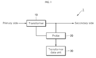
- FIG. 1 is a diagram schematically illustrating the configuration of a transformer load monitoring system in the related art.
- a transformer load monitoring system 1 in the related art includes a transformer 10, a probe 20, and a transformer data unit 30.
- the transformer 10 is installed on an electric pole (not illustrated), and a primary voltage is input to the transformer 10 through a line that is branched from a primary line to which power is transmitted from a substation.
- the primary voltage that is input to the transformer 10 is reduced by a voltage reduction circuit (not illustrated) in the transformer 10 to produce a secondary voltage, and the secondary voltage is transmitted to an outside, for example, a consumer, through a secondary line.
- the probe 20 is a measurement device that is installed adjacent to the transformer 10 to measure the voltage or current that flows from the transformer 10 to the secondary line.
- the transformer data unit 30 is connected to the probe 20 to calculate the power information of the transformer 10 from the voltage or current that is provided from the probe 20.
- the transformer data unit 30 transmits the calculated power information to an upper system (not illustrated).
- the transformer load monitoring system 1 requires accuracy for the power information, and for this, performs error correction between the probe 20 and the transformer data unit 30.
- the transformer load monitoring system 1 corrects an error by performing calibration with respect to self-errors of the transformer data unit 30 and the probe 20 in a state where the transformer data unit 30 and the probe 20 are put into one-to-one correspondence with each other.
- the calibration is performed in a state where the transformer data unit 30 and the probe 20 are not connected to the transformer 10. After completion of the calibration, the transformer data unit 30 and the probe 20 are connected to each other in one-to-one correspondence state.
- the transformer load monitoring system 1 in the related art has the problem that in the case where one of the transformer data unit 30 and the probe 20 is unexpectedly troubled, it is difficult to replace the troubled constituent element.
- the transformer load monitoring system 1 in the related art performs calibration in a state where the transformer data unit 30 and the probe 20 are connected in one-to-one manner, it is required to replace both of the transformer data unit 30 and the probe 20 by other calibrated transformer data unit and probe even if only one of them is troubled.
- the transformer load monitoring system 1 in the related art has the problem that time and cost required for equipment replacement are increased.
- the present invention has been made to solve the above-mentioned problems occurring in the related art, and one subject to be achieved by the present invention is to provide a system for correcting an error, which can perform error correction through calibration even if a transformer data unit and a measurement device are connected in a random combination in a transformer load monitoring system.
- a system for correcting an error which includes a measurement device connected to a secondary output line of a transformer to measure current that is output from the transformer; a transformer data unit configured to determine a usage rate and an overload state through calculation of a load amount for a capacity of the transformer in accordance with the current that is measured by the measurement device; and an emulator connected to the measurement device and the transformer data unit to perform error correction between the measurement device and the transformer data unit through performing calibration at least once.
- the emulator may calibrate the measurement device and the transformer data unit with respect to at least three points within a current measurement range.
- the current measurement range may be 0 to 760A, and the three points may be points of 5A, 150A, and 650A.
- the system for correcting an error may further include a first memory in which a measurement device ID is stored; a second memory in which a transformer data unit ID is stored; and a lookup table in which characteristic values according to the measurement device ID and the transformer data unit ID are stored.
- the emulator may extract one characteristic value which corresponds to the measurement device ID and the transformer data unit ID among the characteristic values of the lookup table, and may calibrate the measurement device and the transformer data unit using the one characteristic value.
- the system for correcting an error can correct the error of the measurement device and the transformer data unit through the calibration using the emulator even if the measurement device and the transformer data unit are connected in the random combination, and thus it becomes possible to replace only one of the measurement device and the transformer data unit.
- the system for correcting an error can reduce the time consumption and the cost occurrence that are required when the measurement device or the transformer data unit is replaced.
- FIG. 2 is a diagram schematically illustrating the configuration of a system for correcting an error according to an embodiment of the present invention.
- a system 100 for correcting an error may include a transformer 110, a measurement device module 120, a transformer data unit 130, and an emulator 140.
- the transformer 110 which is installed on an electric pole (not illustrated), reduces a primary voltage that is provided from a primary line that passes through the electric pole to generate a secondary voltage, and may output the secondary voltage to a consumer through a secondary line.
- the measurement device module 120 can measure an output of the transformer 110, that is, current that flows from the transformer 110 to the secondary line.
- the measurement device module 120 may include a plurality of measurement devices CT_1 to CT_N, for example, a plurality of current measurement probes.
- One of the plurality of measurement devices CT_1 to CT_N may be connected to the transformer data unit 130 to be described later through a wired/wireless method.
- the transformer data unit 130 may calculate information on the transformer 110, for example, a load amount for the capacity of the transformer 110, from the current value of the transformer 110 that is provided from the measurement device module 120. Further, the transformer data unit 130 may determine the usage rate and an overload state of the transformer 110 on the basis of the load amount for the capacity of the transformer 110. The transformer data unit 130 may be connected to one of the plurality of measurement devices CT_1 to CT_N of the measurement device module 120 to receive the current value of the transformer 110.
- the emulator 140 may be connected to the transformer data unit 130 in a wired/wireless method to perform error correction between the transformer data unit 130 and the measurement devices CT_1 to CT_N connected thereto.
- the emulator 140 can correct an error of the transformer data unit 130 and the measurement devices CT_1 to CT_N through calibration.
- the emulator 140 may be composed of a computer having an embedded calibration program, and can correct the error of the transformer data unit 130 and the measurement devices CT_1 to CT_N through performing calibration at least once.
- FIG. 2 illustrates that the system 100 for correcting an error is provided with the measurement device module 120 including the plurality of measurement devices CT_1 to CT_N, but is not limited thereto.
- the system 100 for correcting an error according to the present invention may be composed of one measurement device CT_1 to CT_N and one transformer data unit 130, or may be composed of one measurement device CT_1 to CT_N and a plurality of transformer data units 130.
- the system 100 for correcting an error according to the present invention as illustrated in FIG. 2 is configured to correct an error by performing the calibration through the emulator 140 in a state where the transformer data unit 130 and the measurement devices CT_1 to CT_N are connected in a random combination.
- FIG. 3 is a flowchart illustrating the operation of the system for correcting an error illustrated in FIG. 2 .
- one of the plurality of measurement devices CT_1 to CT_N that are provided in the measurement device module 120 is first connected to the transformer data unit 130, and then the emulator 140 is connected to the transformer data unit 130 (S10).
- the emulator 140 performs calibration between the transformer data unit 130 and the measurement devices CT_1 to CT_N connected thereto using an embedded program, and corrects the error of the transformer data unit 130 and the measurement devices CT_1 to CT_N through this.
- the emulator 140 can correct the error of the transformer data unit 130 and the measurement devices CT_1 to CT_N through three times calibration (S20 to S40).
- the emulator 140 may correct the error by performing the first calibration at the first point of the current measurement range of the measurement devices CT_1 to CT_N or the transformer data unit 130 (S20).
- the current measurement range may be 0 to 760A
- the first point may be a point of 5A.
- the emulator 140 may correct the error by performing the second calibration at the second point of the current measurement range (S30).
- the second point may be a point of 150A.
- the emulator 140 may correct the error by performing the third calibration at the third point of the current measurement range (S40).
- the third point may be a point of 650A.
- the system 100 for correcting an error can correct the error of the transformer data unit 130 and the measurement devices CT_1 to CT_N connected thereto by performing the calibration between the transformer data unit 130 and the measurement devices CT_1 to CT_N using the emulator 140 even if one of the plurality of measurement devices CT_1 to CT_N of the measurement device module 120 is connected to the transformer data unit 130.
- the system 100 for correcting an error in comparison to the system in the related art, it is possible to replace only one of the transformer data unit 130 and the measurement devices CT_1 to CT_N, and thus the time consumption and the cost occurrence caused by the replacement can be reduced.
- FIG. 4 is a diagram schematically illustrating the configuration of a system for correcting an error according to another embodiment of the present invention.
- a system 101 for correcting an error may include a transformer 110, a measurement device 121, a transformer data unit 131, and an emulator 141.
- the transformer 110 is the same as the transformer as described above with reference to FIG. 2 , and reduces a primary voltage that is provided through a primary line to generate a secondary voltage, and outputs the secondary voltage through a secondary line.
- the measurement device 121 can measure an output of the transformer 110, and can output the measured current to the transformer data unit 131.
- the measurement device 121 may include a first memory 125. Inherent ID information of the measurement device 121 may be stored in the first memory 125.
- the transformer data unit 131 may calculate a load amount for the capacity of the transformer 110, from the current value that is provided from the measurement device 121, and may determine the usage rate and an overload state of the transformer 110 based on this.
- the transformer data unit 131 may include a second memory 135. Inherent ID information of the transformer data unit 131 may be stored in the second memory 135.
- the emulator 141 may be connected to the transformer data unit 131 to perform error correction between the transformer data unit 131 and the measurement device 121.
- the emulator 141 can correct an error of the transformer data unit 131 and the measurement device 121 through performing calibration at least once.
- the emulator 140 may include a lookup table 145.
- characteristic values for calibration between the transformer data unit 131 and the measurement device 121 may be stored.
- the emulator 141 may detect the measurement device ID from the first memory 125 of the measurement device 121, and may detect the transformer data unit ID from the second memory 135 of the transformer data unit 131. Further, the emulator 141 may extract the characteristic values corresponding to the measurement device ID and the transformer data unit ID from the lookup table 145, and may perform calibration between the transformer data unit 131 and the measurement device 121 using the extracted characteristic value.
- the memory is provided in the measurement device 121 and the transformer data unit 131, and the measurement device ID and the transformer data unit ID are stored in the memory, but are not limited thereto.
- the measurement device ID and the transformer data unit ID may be in the form of barcodes, and such IDs may be attached to outer surfaces of the measurement device 121 and the transformer data unit 131.
- the emulator 141 may be acquired the measurement ID and the transformer data unit ID by recognizing the barcode through a reader or the like.
- FIG. 5 is a flowchart illustrating the operation of the system for correcting an error illustrated in FIG. 4
- FIG. 6 is a diagram exemplifying a lookup table of an emulator.
- the emulator 141 may be connected to the transformer data unit 131 (S110).
- the emulator 141 may detect the measurement device ID that is stored in the first memory 125 of the measurement device 121 (S120), and may detect the transformer data unit ID that is stored in the second memory 135 of the transformer data unit 131 (S130).
- the emulator 141 may extract the characteristic values corresponding to the measurement device ID and the transformer data unit ID from the internal lookup table 145 (S140), and may correct the error by performing calibration of the measurement device 121 and the transformer data unit 131 in accordance with the extracted characteristic value (S150).
- a plurality of characteristic values ⁇ 1 to yn which correspond to a plurality of measurement device IDs ID_P1 to ID_Pm and transformer data unit IDs ID_T1 to ID_Tn, are stored in the lookup table 145 of the emulator 141.
- the emulator 141 may extract ⁇ 1 from the lookup table 145 as the characteristic value.
- the emulator 141 may correct the error by performing the calibration of the measurement device 121 and the transformer data unit 131 in accordance with the extracted characteristic value ⁇ 1.
- the system 101 for correcting an error can correct the error of the measurement device 121 and the transformer data unit 131 by performing the calibration between the measurement device 121 and the transformer data unit 131 using the characteristic values extracted according to the ID information stored therein even if the measurement device 121 and the transformer data unit 131 are connected in the random combination.
- the system 101 for correcting an error in comparison to the system in the related art, it is possible to replace only one of the transformer data unit 131 and the measurement device 121, and thus the time consumption and the cost occurrence caused by the replacement can be reduced.
- the system for correcting an error can correct the error of the measurement device and the transformer data unit through the calibration using the emulator, the measurement device and the transformer data unit can be randomly combined. Accordingly, the measurement device and the transformer data unit can be easily replaced, and thus the time and the cost required for the repair can be reduced.
Landscapes
- Engineering & Computer Science (AREA)
- Power Engineering (AREA)
- Physics & Mathematics (AREA)
- General Physics & Mathematics (AREA)
- Measurement Of Current Or Voltage (AREA)
- Testing Or Calibration Of Command Recording Devices (AREA)
Abstract
Description
- The present invention relates to a system for correcting an error, and more particularly, to a system for correcting an error, which can correct an error through performing calibration between a transformer data unit and a measurement device in a transformer load monitoring system.
- A transformer data unit (TDU) that is provided in a data concentrate unit (DCU) constitutes a transformer load monitoring system together with a measurement device that measures current or voltage from a transformer, for example, a probe.
- The transformer load monitoring system calculates power information, such as current for each phase, a voltage, an active power amount, a reactive power amount, and a power factor, in accordance with transformer current and voltage that are transmitted from the measurement device to the transformer data unit, and then transmits the calculated power information to an upper server system to perform real-time transformer monitoring and diagnosis.
- The transformer load monitoring system requires accuracy for the calculated power information. For this, the transformer load monitoring system essentially requires calibration for error correction between the transformer data unit and the measurement device.
-
FIG. 1 is a diagram schematically illustrating the configuration of a transformer load monitoring system in the related art. - Referring to
FIG. 1 , a transformerload monitoring system 1 in the related art includes atransformer 10, aprobe 20, and atransformer data unit 30. - The
transformer 10 is installed on an electric pole (not illustrated), and a primary voltage is input to thetransformer 10 through a line that is branched from a primary line to which power is transmitted from a substation. - The primary voltage that is input to the
transformer 10 is reduced by a voltage reduction circuit (not illustrated) in thetransformer 10 to produce a secondary voltage, and the secondary voltage is transmitted to an outside, for example, a consumer, through a secondary line. - The
probe 20 is a measurement device that is installed adjacent to thetransformer 10 to measure the voltage or current that flows from thetransformer 10 to the secondary line. - The
transformer data unit 30 is connected to theprobe 20 to calculate the power information of thetransformer 10 from the voltage or current that is provided from theprobe 20. Thetransformer data unit 30 transmits the calculated power information to an upper system (not illustrated). - As described above, the transformer
load monitoring system 1 requires accuracy for the power information, and for this, performs error correction between theprobe 20 and thetransformer data unit 30. - The transformer
load monitoring system 1 corrects an error by performing calibration with respect to self-errors of thetransformer data unit 30 and theprobe 20 in a state where thetransformer data unit 30 and theprobe 20 are put into one-to-one correspondence with each other. - In this case, the calibration is performed in a state where the
transformer data unit 30 and theprobe 20 are not connected to thetransformer 10. After completion of the calibration, thetransformer data unit 30 and theprobe 20 are connected to each other in one-to-one correspondence state. - However, the transformer
load monitoring system 1 in the related art has the problem that in the case where one of thetransformer data unit 30 and theprobe 20 is unexpectedly troubled, it is difficult to replace the troubled constituent element. - That is, since the transformer
load monitoring system 1 in the related art performs calibration in a state where thetransformer data unit 30 and theprobe 20 are connected in one-to-one manner, it is required to replace both of thetransformer data unit 30 and theprobe 20 by other calibrated transformer data unit and probe even if only one of them is troubled. - Accordingly, the transformer
load monitoring system 1 in the related art has the problem that time and cost required for equipment replacement are increased. - Accordingly, the present invention has been made to solve the above-mentioned problems occurring in the related art, and one subject to be achieved by the present invention is to provide a system for correcting an error, which can perform error correction through calibration even if a transformer data unit and a measurement device are connected in a random combination in a transformer load monitoring system.
- In accordance with an aspect of the present invention, there is provided a system for correcting an error, which includes a measurement device connected to a secondary output line of a transformer to measure current that is output from the transformer; a transformer data unit configured to determine a usage rate and an overload state through calculation of a load amount for a capacity of the transformer in accordance with the current that is measured by the measurement device; and an emulator connected to the measurement device and the transformer data unit to perform error correction between the measurement device and the transformer data unit through performing calibration at least once.
- The emulator may calibrate the measurement device and the transformer data unit with respect to at least three points within a current measurement range.
- The current measurement range may be 0 to 760A, and the three points may be points of 5A, 150A, and 650A.
- The system for correcting an error may further include a first memory in which a measurement device ID is stored; a second memory in which a transformer data unit ID is stored; and a lookup table in which characteristic values according to the measurement device ID and the transformer data unit ID are stored.
- The emulator may extract one characteristic value which corresponds to the measurement device ID and the transformer data unit ID among the characteristic values of the lookup table, and may calibrate the measurement device and the transformer data unit using the one characteristic value.
- The system for correcting an error according to the present invention can correct the error of the measurement device and the transformer data unit through the calibration using the emulator even if the measurement device and the transformer data unit are connected in the random combination, and thus it becomes possible to replace only one of the measurement device and the transformer data unit.
- Through this, the system for correcting an error according to the present invention can reduce the time consumption and the cost occurrence that are required when the measurement device or the transformer data unit is replaced.
-
-
FIG. 1 is a diagram schematically illustrating the configuration of a transformer load monitoring system in the related art. -
FIG. 2 is a diagram schematically illustrating the configuration of a system for correcting an error according to an embodiment of the present invention. -
FIG. 3 is a flowchart illustrating the operation of the system for correcting an error illustrated inFIG. 2 . -
FIG. 4 is a diagram schematically illustrating the configuration of a system for correcting an error according to another embodiment of the present invention. -
FIG. 5 is a flowchart illustrating the operation of the system for correcting an error illustrated inFIG. 4 . -
FIG. 6 is a diagram exemplifying a lookup table of an emulator. - Hereinafter, embodiments of the present invention will be described in detail with reference to the accompanying drawings. It should be understood that the present invention is not limited to the following embodiments, and that the embodiments are provided for illustrative purposes only. The scope of the invention should be defined only by the accompanying claims and equivalents thereof.
-
FIG. 2 is a diagram schematically illustrating the configuration of a system for correcting an error according to an embodiment of the present invention. - Referring to
FIG. 2 , asystem 100 for correcting an error according to this embodiment may include atransformer 110, ameasurement device module 120, atransformer data unit 130, and anemulator 140. - The
transformer 110, which is installed on an electric pole (not illustrated), reduces a primary voltage that is provided from a primary line that passes through the electric pole to generate a secondary voltage, and may output the secondary voltage to a consumer through a secondary line. - The
measurement device module 120 can measure an output of thetransformer 110, that is, current that flows from thetransformer 110 to the secondary line. - The
measurement device module 120 may include a plurality of measurement devices CT_1 to CT_N, for example, a plurality of current measurement probes. One of the plurality of measurement devices CT_1 to CT_N may be connected to thetransformer data unit 130 to be described later through a wired/wireless method. - The
transformer data unit 130 may calculate information on thetransformer 110, for example, a load amount for the capacity of thetransformer 110, from the current value of thetransformer 110 that is provided from themeasurement device module 120. Further, thetransformer data unit 130 may determine the usage rate and an overload state of thetransformer 110 on the basis of the load amount for the capacity of thetransformer 110. Thetransformer data unit 130 may be connected to one of the plurality of measurement devices CT_1 to CT_N of themeasurement device module 120 to receive the current value of thetransformer 110. - The
emulator 140 may be connected to thetransformer data unit 130 in a wired/wireless method to perform error correction between thetransformer data unit 130 and the measurement devices CT_1 to CT_N connected thereto. - The
emulator 140 can correct an error of thetransformer data unit 130 and the measurement devices CT_1 to CT_N through calibration. Theemulator 140 may be composed of a computer having an embedded calibration program, and can correct the error of thetransformer data unit 130 and the measurement devices CT_1 to CT_N through performing calibration at least once. - On the other hand,
FIG. 2 illustrates that thesystem 100 for correcting an error is provided with themeasurement device module 120 including the plurality of measurement devices CT_1 to CT_N, but is not limited thereto. - For example, the
system 100 for correcting an error according to the present invention may be composed of one measurement device CT_1 to CT_N and onetransformer data unit 130, or may be composed of one measurement device CT_1 to CT_N and a plurality oftransformer data units 130. - That is, the
system 100 for correcting an error according to the present invention as illustrated inFIG. 2 is configured to correct an error by performing the calibration through theemulator 140 in a state where thetransformer data unit 130 and the measurement devices CT_1 to CT_N are connected in a random combination. -
FIG. 3 is a flowchart illustrating the operation of the system for correcting an error illustrated inFIG. 2 . - Referring to
FIGS. 2 and3 , one of the plurality of measurement devices CT_1 to CT_N that are provided in themeasurement device module 120 is first connected to thetransformer data unit 130, and then theemulator 140 is connected to the transformer data unit 130 (S10). - Then, the
emulator 140 performs calibration between thetransformer data unit 130 and the measurement devices CT_1 to CT_N connected thereto using an embedded program, and corrects the error of thetransformer data unit 130 and the measurement devices CT_1 to CT_N through this. For example, theemulator 140 can correct the error of thetransformer data unit 130 and the measurement devices CT_1 to CT_N through three times calibration (S20 to S40). - First, the
emulator 140 may correct the error by performing the first calibration at the first point of the current measurement range of the measurement devices CT_1 to CT_N or the transformer data unit 130 (S20). Here, the current measurement range may be 0 to 760A, and the first point may be a point of 5A. - In continuation, the
emulator 140 may correct the error by performing the second calibration at the second point of the current measurement range (S30). Here, the second point may be a point of 150A. - Then, the
emulator 140 may correct the error by performing the third calibration at the third point of the current measurement range (S40). Here, the third point may be a point of 650A. - As described above, the
system 100 for correcting an error according to this embodiment can correct the error of thetransformer data unit 130 and the measurement devices CT_1 to CT_N connected thereto by performing the calibration between thetransformer data unit 130 and the measurement devices CT_1 to CT_N using theemulator 140 even if one of the plurality of measurement devices CT_1 to CT_N of themeasurement device module 120 is connected to thetransformer data unit 130. - According to the
system 100 for correcting an error according to the present invention, in comparison to the system in the related art, it is possible to replace only one of thetransformer data unit 130 and the measurement devices CT_1 to CT_N, and thus the time consumption and the cost occurrence caused by the replacement can be reduced. -
FIG. 4 is a diagram schematically illustrating the configuration of a system for correcting an error according to another embodiment of the present invention. - Referring to
FIG. 4 , asystem 101 for correcting an error according to this embodiment may include atransformer 110, ameasurement device 121, atransformer data unit 131, and anemulator 141. - The
transformer 110 is the same as the transformer as described above with reference toFIG. 2 , and reduces a primary voltage that is provided through a primary line to generate a secondary voltage, and outputs the secondary voltage through a secondary line. - The
measurement device 121 can measure an output of thetransformer 110, and can output the measured current to thetransformer data unit 131. - The
measurement device 121 may include afirst memory 125. Inherent ID information of themeasurement device 121 may be stored in thefirst memory 125. - The
transformer data unit 131 may calculate a load amount for the capacity of thetransformer 110, from the current value that is provided from themeasurement device 121, and may determine the usage rate and an overload state of thetransformer 110 based on this. - The
transformer data unit 131 may include asecond memory 135. Inherent ID information of thetransformer data unit 131 may be stored in thesecond memory 135. - The
emulator 141 may be connected to thetransformer data unit 131 to perform error correction between thetransformer data unit 131 and themeasurement device 121. Theemulator 141 can correct an error of thetransformer data unit 131 and themeasurement device 121 through performing calibration at least once. - The
emulator 140 may include a lookup table 145. In the lookup table, characteristic values for calibration between thetransformer data unit 131 and themeasurement device 121 may be stored. - The
emulator 141 may detect the measurement device ID from thefirst memory 125 of themeasurement device 121, and may detect the transformer data unit ID from thesecond memory 135 of thetransformer data unit 131. Further, theemulator 141 may extract the characteristic values corresponding to the measurement device ID and the transformer data unit ID from the lookup table 145, and may perform calibration between thetransformer data unit 131 and themeasurement device 121 using the extracted characteristic value. - On the other hand, in this embodiment, the memory is provided in the
measurement device 121 and thetransformer data unit 131, and the measurement device ID and the transformer data unit ID are stored in the memory, but are not limited thereto. - For example, the measurement device ID and the transformer data unit ID may be in the form of barcodes, and such IDs may be attached to outer surfaces of the
measurement device 121 and thetransformer data unit 131. Further, theemulator 141 may be acquired the measurement ID and the transformer data unit ID by recognizing the barcode through a reader or the like. -
FIG. 5 is a flowchart illustrating the operation of the system for correcting an error illustrated inFIG. 4 , andFIG. 6 is a diagram exemplifying a lookup table of an emulator. - Referring to
FIGS. 4 and5 , after themeasurement device 121 and thetransformer data unit 131 are connected, theemulator 141 may be connected to the transformer data unit 131 (S110). - Then, the
emulator 141 may detect the measurement device ID that is stored in thefirst memory 125 of the measurement device 121 (S120), and may detect the transformer data unit ID that is stored in thesecond memory 135 of the transformer data unit 131 (S130). - Then, the
emulator 141 may extract the characteristic values corresponding to the measurement device ID and the transformer data unit ID from the internal lookup table 145 (S140), and may correct the error by performing calibration of themeasurement device 121 and thetransformer data unit 131 in accordance with the extracted characteristic value (S150). - That is, as illustrated in
FIG. 6 , a plurality of characteristic values α1 to yn, which correspond to a plurality of measurement device IDs ID_P1 to ID_Pm and transformer data unit IDs ID_T1 to ID_Tn, are stored in the lookup table 145 of theemulator 141. - For example, if ID_P1 is detected from the
first memory 125 of themeasurement device 121 as the measurement device ID, and ID_T1 is detected from thesecond memory 135 of thetransformer data unit 131 as the transformer data unit ID, theemulator 141 may extract α1 from the lookup table 145 as the characteristic value. - Further, the
emulator 141 may correct the error by performing the calibration of themeasurement device 121 and thetransformer data unit 131 in accordance with the extracted characteristic value α1. - As described above, the
system 101 for correcting an error according to the embodiments of the present invention can correct the error of themeasurement device 121 and thetransformer data unit 131 by performing the calibration between themeasurement device 121 and thetransformer data unit 131 using the characteristic values extracted according to the ID information stored therein even if themeasurement device 121 and thetransformer data unit 131 are connected in the random combination. - According to the
system 101 for correcting an error according to the present invention, in comparison to the system in the related art, it is possible to replace only one of thetransformer data unit 131 and themeasurement device 121, and thus the time consumption and the cost occurrence caused by the replacement can be reduced. - On the other hand, since the system for correcting an error according to still another embodiment can correct the error of the measurement device and the transformer data unit through the calibration using the emulator, the measurement device and the transformer data unit can be randomly combined. Accordingly, the measurement device and the transformer data unit can be easily replaced, and thus the time and the cost required for the repair can be reduced.
- Although the present invention has been described with reference to some embodiments in the attached figures, it is to be understood that various equivalent modifications and variations of the embodiments can be made by a person having an ordinary skill in the art without departing from the spirit and scope of the present invention. The scope of the present invention could be defined by the appended claims and their equivalents.
Claims (5)
- A system for correcting an error for a transformer load monitoring system, the system comprising:a measurement device (CT_1∼CT_N) connected to a secondary output line of a transformer to measure current that is output from the transformer;a transformer data unit (130) configured to determine a usage rate and an overload state through calculation of a load amount for a capacity of the transformer in accordance with the current that is measured by the measurement device; andan emulator (140) connected to the measurement device and the transformer data unit to perform error correction between the measurement device and the transformer data unit through performing calibration at least once.
- The system for correcting an error according to claim 1, wherein the emulator calibrates the measurement device and the transformer data unit with respect to at least three points within a current measurement range.
- The system for correcting an error according to claim 2, wherein the current measurement range is 0 to 760A, and the three points are points of 5A, 150A, and 650A.
- The system for correcting an error according to claim 1, further comprising:a first memory (125) in which a measurement device ID is stored;a second memory (135) in which a transformer data unit ID is stored; anda lookup table (145) in which characteristic values according to the measurement device ID and the transformer data unit ID are stored.
- The system for correcting an error according to claim 4, wherein the emulator extracts one characteristic value which corresponds to the measurement device ID and the transformer data unit ID among the characteristic values of the lookup table, and calibrates the measurement device and the transformer data unit using the one characteristic value.
Applications Claiming Priority (1)
| Application Number | Priority Date | Filing Date | Title |
|---|---|---|---|
| KR1020150101223A KR102015499B1 (en) | 2015-07-16 | 2015-07-16 | System for correcting error |
Publications (1)
| Publication Number | Publication Date |
|---|---|
| EP3118645A1 true EP3118645A1 (en) | 2017-01-18 |
Family
ID=56855255
Family Applications (1)
| Application Number | Title | Priority Date | Filing Date |
|---|---|---|---|
| EP16176024.4A Withdrawn EP3118645A1 (en) | 2015-07-16 | 2016-06-23 | System for correcting error |
Country Status (3)
| Country | Link |
|---|---|
| US (1) | US10067216B2 (en) |
| EP (1) | EP3118645A1 (en) |
| KR (1) | KR102015499B1 (en) |
Cited By (3)
| Publication number | Priority date | Publication date | Assignee | Title |
|---|---|---|---|---|
| CN107220906A (en) * | 2017-05-31 | 2017-09-29 | 国网上海市电力公司 | Multiple Time Scales multiplexing electric abnormality analysis method based on electricity consumption acquisition system |
| CN107340492A (en) * | 2017-05-31 | 2017-11-10 | 国网上海市电力公司 | Electric power meter failure analysis methods with scene anticipation are excavated based on big data |
| EP3495833A1 (en) * | 2017-12-07 | 2019-06-12 | ABB Schweiz AG | A method of compensating current transformer errors |
Citations (5)
| Publication number | Priority date | Publication date | Assignee | Title |
|---|---|---|---|---|
| EP0984287A1 (en) * | 1998-08-31 | 2000-03-08 | Hewlett-Packard Company | Oscilloscope probe having stored probe identification |
| WO2001029572A1 (en) * | 1999-10-21 | 2001-04-26 | Siemens Power Transmission & Distribution, Inc. | External transformer correction in an electricity meter |
| US20060085144A1 (en) * | 2004-10-18 | 2006-04-20 | Electro Industries/Gauge Tech. | System and method for compensating for potential and current transformers in energy meters |
| US20120217954A1 (en) * | 2011-02-25 | 2012-08-30 | Veris Industries, Llc | Current meter with voltage awareness |
| KR101326730B1 (en) * | 2012-05-22 | 2013-11-08 | 한전케이디엔주식회사 | Calibration device for transformer monitoring module |
Family Cites Families (9)
| Publication number | Priority date | Publication date | Assignee | Title |
|---|---|---|---|---|
| JP3955706B2 (en) | 2000-02-02 | 2007-08-08 | 三菱電機株式会社 | Circuit breaker with energization information measuring device and correction method thereof |
| JP2002207058A (en) | 2001-01-11 | 2002-07-26 | Nissin Electric Co Ltd | Auxiliary current transformer compensating method for automatic oscilloscope |
| KR101001499B1 (en) | 2003-11-03 | 2010-12-14 | 주식회사 케이티 | Power meter |
| US20070007942A1 (en) | 2005-07-08 | 2007-01-11 | Microchip Technology Incorporated | Automatic non-linear phase response calibration and compensation for a power measurement device |
| JP2008046067A (en) | 2006-08-21 | 2008-02-28 | Chugoku Electric Power Co Inc:The | Error correction method in current measurement |
| US20100270658A1 (en) | 2007-12-27 | 2010-10-28 | Kazuo Nakagawa | Semiconductor device and method for producing same |
| JP5255554B2 (en) | 2009-12-18 | 2013-08-07 | 株式会社日立産機システム | Characteristic monitoring device for current transformers or transformers |
| JP5560828B2 (en) * | 2010-03-26 | 2014-07-30 | 東京電力株式会社 | Transformer load estimation method |
| KR101509149B1 (en) | 2013-09-25 | 2015-04-07 | 한전케이디엔주식회사 | Smart gateway |
-
2015
- 2015-07-16 KR KR1020150101223A patent/KR102015499B1/en not_active Expired - Fee Related
-
2016
- 2016-06-23 EP EP16176024.4A patent/EP3118645A1/en not_active Withdrawn
- 2016-07-14 US US15/210,794 patent/US10067216B2/en not_active Expired - Fee Related
Patent Citations (5)
| Publication number | Priority date | Publication date | Assignee | Title |
|---|---|---|---|---|
| EP0984287A1 (en) * | 1998-08-31 | 2000-03-08 | Hewlett-Packard Company | Oscilloscope probe having stored probe identification |
| WO2001029572A1 (en) * | 1999-10-21 | 2001-04-26 | Siemens Power Transmission & Distribution, Inc. | External transformer correction in an electricity meter |
| US20060085144A1 (en) * | 2004-10-18 | 2006-04-20 | Electro Industries/Gauge Tech. | System and method for compensating for potential and current transformers in energy meters |
| US20120217954A1 (en) * | 2011-02-25 | 2012-08-30 | Veris Industries, Llc | Current meter with voltage awareness |
| KR101326730B1 (en) * | 2012-05-22 | 2013-11-08 | 한전케이디엔주식회사 | Calibration device for transformer monitoring module |
Cited By (5)
| Publication number | Priority date | Publication date | Assignee | Title |
|---|---|---|---|---|
| CN107220906A (en) * | 2017-05-31 | 2017-09-29 | 国网上海市电力公司 | Multiple Time Scales multiplexing electric abnormality analysis method based on electricity consumption acquisition system |
| CN107340492A (en) * | 2017-05-31 | 2017-11-10 | 国网上海市电力公司 | Electric power meter failure analysis methods with scene anticipation are excavated based on big data |
| CN107220906B (en) * | 2017-05-31 | 2019-10-11 | 国网上海市电力公司 | Multi-time scale power consumption anomaly analysis method based on power collection system |
| CN107340492B (en) * | 2017-05-31 | 2020-01-21 | 国网上海市电力公司 | Fault analysis method of electric energy metering device based on big data mining and scene prediction |
| EP3495833A1 (en) * | 2017-12-07 | 2019-06-12 | ABB Schweiz AG | A method of compensating current transformer errors |
Also Published As
| Publication number | Publication date |
|---|---|
| US10067216B2 (en) | 2018-09-04 |
| US20170016973A1 (en) | 2017-01-19 |
| KR20170009352A (en) | 2017-01-25 |
| KR102015499B1 (en) | 2019-08-28 |
Similar Documents
| Publication | Publication Date | Title |
|---|---|---|
| CN108089141B (en) | Error correction method and device of current measuring device based on current divider | |
| EP2365348B1 (en) | Monitoring apparatus for current transformer | |
| KR101681288B1 (en) | Method for error calibration of electric power device | |
| CN104297717A (en) | Electric energy meter correction method and system and electric energy meter | |
| US20160077164A1 (en) | Failure sign diagnosis system of electrical power grid and method thereof | |
| US20170108550A1 (en) | Monitoring device for a surge arrester and monitoring system comprising a monitoring device | |
| EP3071986B1 (en) | Electricity meter with fault detection mechanism and fault detection method | |
| US20140119084A1 (en) | AC Input Voltage Detection Circuit and AC/DC Power Source | |
| US20170219653A1 (en) | Detecting method and apparatus for abnormal electrical connection in main circuit of switchgear | |
| US10067216B2 (en) | System for correcting error | |
| CN114047472A (en) | Metering error monitoring system of intelligent electric meter and monitoring method and device thereof | |
| JP2016161302A (en) | Accident point locating device and method, power system monitoring system, facility planning support system | |
| CN103926485B (en) | Judgment method of power outage event based on electric energy collection terminal | |
| CN113009406A (en) | Electric quantity measurement correction method and device and air conditioning system | |
| KR102357052B1 (en) | Current no aberration measurement device of living electricity condition and the monitoring sysytem | |
| KR102092065B1 (en) | Electronic wattmeter with tolerance minimization and Automatic Calibration | |
| TWI609187B (en) | Insulation monitoring device | |
| CN113820640A (en) | Measurement abnormality identification control method, computer equipment and storage medium | |
| KR101957729B1 (en) | Apparatus for measurementing isolation having self calibration function and method thereof | |
| KR101373460B1 (en) | Electrode check method and system of body composition measuring device | |
| JP2011149959A (en) | Insulation monitoring device | |
| CN104101856A (en) | Method and device for detecting error of electronic measurement unit of zero-flux DC (Direct Current) current transformer | |
| KR20170008584A (en) | Electric power measuring system | |
| CN104360189B (en) | A kind of grid power blackout event judgment method | |
| JP2008157838A (en) | Insulation monitoring device |
Legal Events
| Date | Code | Title | Description |
|---|---|---|---|
| PUAI | Public reference made under article 153(3) epc to a published international application that has entered the european phase |
Free format text: ORIGINAL CODE: 0009012 |
|
| STAA | Information on the status of an ep patent application or granted ep patent |
Free format text: STATUS: THE APPLICATION HAS BEEN PUBLISHED |
|
| AK | Designated contracting states |
Kind code of ref document: A1 Designated state(s): AL AT BE BG CH CY CZ DE DK EE ES FI FR GB GR HR HU IE IS IT LI LT LU LV MC MK MT NL NO PL PT RO RS SE SI SK SM TR |
|
| AX | Request for extension of the european patent |
Extension state: BA ME |
|
| STAA | Information on the status of an ep patent application or granted ep patent |
Free format text: STATUS: REQUEST FOR EXAMINATION WAS MADE |
|
| 17P | Request for examination filed |
Effective date: 20170714 |
|
| RBV | Designated contracting states (corrected) |
Designated state(s): AL AT BE BG CH CY CZ DE DK EE ES FI FR GB GR HR HU IE IS IT LI LT LU LV MC MK MT NL NO PL PT RO RS SE SI SK SM TR |
|
| STAA | Information on the status of an ep patent application or granted ep patent |
Free format text: STATUS: EXAMINATION IS IN PROGRESS |
|
| 17Q | First examination report despatched |
Effective date: 20200504 |
|
| STAA | Information on the status of an ep patent application or granted ep patent |
Free format text: STATUS: THE APPLICATION IS DEEMED TO BE WITHDRAWN |
|
| 18D | Application deemed to be withdrawn |
Effective date: 20230103 |