EP3118519A1 - Fuel injector - Google Patents
Fuel injector Download PDFInfo
- Publication number
- EP3118519A1 EP3118519A1 EP16173682.2A EP16173682A EP3118519A1 EP 3118519 A1 EP3118519 A1 EP 3118519A1 EP 16173682 A EP16173682 A EP 16173682A EP 3118519 A1 EP3118519 A1 EP 3118519A1
- Authority
- EP
- European Patent Office
- Prior art keywords
- injection system
- fuel injection
- vanes
- exposed surface
- fuel
- Prior art date
- Legal status (The legal status is an assumption and is not a legal conclusion. Google has not performed a legal analysis and makes no representation as to the accuracy of the status listed.)
- Granted
Links
Images




Classifications
-
- F—MECHANICAL ENGINEERING; LIGHTING; HEATING; WEAPONS; BLASTING
- F23—COMBUSTION APPARATUS; COMBUSTION PROCESSES
- F23R—GENERATING COMBUSTION PRODUCTS OF HIGH PRESSURE OR HIGH VELOCITY, e.g. GAS-TURBINE COMBUSTION CHAMBERS
- F23R3/00—Continuous combustion chambers using liquid or gaseous fuel
- F23R3/02—Continuous combustion chambers using liquid or gaseous fuel characterised by the air-flow or gas-flow configuration
- F23R3/16—Continuous combustion chambers using liquid or gaseous fuel characterised by the air-flow or gas-flow configuration with devices inside the flame tube or the combustion chamber to influence the air or gas flow
- F23R3/18—Flame stabilising means, e.g. flame holders for after-burners of jet-propulsion plants
- F23R3/20—Flame stabilising means, e.g. flame holders for after-burners of jet-propulsion plants incorporating fuel injection means
-
- F—MECHANICAL ENGINEERING; LIGHTING; HEATING; WEAPONS; BLASTING
- F02—COMBUSTION ENGINES; HOT-GAS OR COMBUSTION-PRODUCT ENGINE PLANTS
- F02C—GAS-TURBINE PLANTS; AIR INTAKES FOR JET-PROPULSION PLANTS; CONTROLLING FUEL SUPPLY IN AIR-BREATHING JET-PROPULSION PLANTS
- F02C7/00—Features, components parts, details or accessories, not provided for in, or of interest apart form groups F02C1/00 - F02C6/00; Air intakes for jet-propulsion plants
- F02C7/22—Fuel supply systems
- F02C7/222—Fuel flow conduits, e.g. manifolds
-
- F—MECHANICAL ENGINEERING; LIGHTING; HEATING; WEAPONS; BLASTING
- F23—COMBUSTION APPARATUS; COMBUSTION PROCESSES
- F23D—BURNERS
- F23D11/00—Burners using a direct spraying action of liquid droplets or vaporised liquid into the combustion space
- F23D11/10—Burners using a direct spraying action of liquid droplets or vaporised liquid into the combustion space the spraying being induced by a gaseous medium, e.g. water vapour
- F23D11/106—Burners using a direct spraying action of liquid droplets or vaporised liquid into the combustion space the spraying being induced by a gaseous medium, e.g. water vapour medium and fuel meeting at the burner outlet
- F23D11/107—Burners using a direct spraying action of liquid droplets or vaporised liquid into the combustion space the spraying being induced by a gaseous medium, e.g. water vapour medium and fuel meeting at the burner outlet at least one of both being subjected to a swirling motion
-
- F—MECHANICAL ENGINEERING; LIGHTING; HEATING; WEAPONS; BLASTING
- F23—COMBUSTION APPARATUS; COMBUSTION PROCESSES
- F23R—GENERATING COMBUSTION PRODUCTS OF HIGH PRESSURE OR HIGH VELOCITY, e.g. GAS-TURBINE COMBUSTION CHAMBERS
- F23R3/00—Continuous combustion chambers using liquid or gaseous fuel
- F23R3/28—Continuous combustion chambers using liquid or gaseous fuel characterised by the fuel supply
- F23R3/34—Feeding into different combustion zones
- F23R3/343—Pilot flames, i.e. fuel nozzles or injectors using only a very small proportion of the total fuel to insure continuous combustion
-
- F—MECHANICAL ENGINEERING; LIGHTING; HEATING; WEAPONS; BLASTING
- F23—COMBUSTION APPARATUS; COMBUSTION PROCESSES
- F23D—BURNERS
- F23D2900/00—Special features of, or arrangements for burners using fluid fuels or solid fuels suspended in a carrier gas
- F23D2900/11401—Flame intercepting baffles forming part of burner head
-
- F—MECHANICAL ENGINEERING; LIGHTING; HEATING; WEAPONS; BLASTING
- F23—COMBUSTION APPARATUS; COMBUSTION PROCESSES
- F23R—GENERATING COMBUSTION PRODUCTS OF HIGH PRESSURE OR HIGH VELOCITY, e.g. GAS-TURBINE COMBUSTION CHAMBERS
- F23R2900/00—Special features of, or arrangements for continuous combustion chambers; Combustion processes therefor
- F23R2900/00014—Reducing thermo-acoustic vibrations by passive means, e.g. by Helmholtz resonators
Definitions
- This invention concerns fuel injector assemblies for gas turbine engines.
- Advanced gas turbine combustors must meet these requirements for lower NOx emissions under conditions in which the control of NOx generation is very challenging.
- UEET Ultra Efficient Engine Technology
- the goal for the Ultra Efficient Engine Technology (UEET) gas turbine combustor research being done by' NASA is a 70 percent reduction in NOx emissions and a 15 percent improvement in fuel efficiency compared to ICAO 1996 standards technology.
- Realisation of the fuel efficiency objectives will require an overall cycle pressure ratio as high as 60 to 1 and a peak cycle temperature of 1600 degrees centigrade or greater.
- the severe combustor pressure and temperature conditions required for improved fuel efficiency make the NOx emissions goal much more difficult to achieve.
- staged low NOx fuel injectors that seek to address this issue have concentrically arranged pilot and main injectors with the main injector surrounding the pilot injector.
- typical staged low NOx injector arrangements have several operational disadvantages, including for example, flame stability and re-light characteristics, the potential for excessive combustor dynamics or pressure fluctuations caused by combustor instability.
- Combustion instability occurs when the heat release couples with combustor acoustics such that random pressure perturbations in the combustor are amplified into larger pressure oscillations.
- a pressure wave generated by acoustic resonance in the combustor coherently interacts with an oncoming fuel-air mixture (reactants) from the fuel injector.
- the reactants feed the combustion flame with a heat release frequency which is coherent with the pressure wave and this can result in a positive growth rate or resonance of the pressure wave and consequently greater noise.
- the nature of the interaction of the incident acoustic wave with the reactants is such as to impair characteristics of the reactants and consequently the quality of the combustion.
- a fuel injection system for a gas turbine comprising; a main airblast fuel injector section, the main airblast fuel injector section having an aft end facing a combustion chamber and wherein a surface exposed to air flow through the injection system is non-axisymmetric, or, non-planar in a reference circumferential plane, and configured to generate acoustic impedance at or adjacent the aft end where, in use, the airflow collides with an oncoming acoustic wave.
- the fuel injection system may further comprise a pilot fuel injector section and the surface may be a surface of the pilot fuel injector section.
- Characteristics of the reactants which may affect interaction with an oncoming acoustic wave include; the fuel flux (i.e. the mass flow of the mixture) to the flame, the stoichiometry (i.e. air to fuel ratio), mixture properties such as drop size distribution and droplet dispersion, or the velocity vector of the reactants (fuel placement).
- Fuel injectors are conventionally designed for a given air and fuel pressure drop but without contemplation of acoustic impedance.
- the fuel injection system of the present invention addresses the issue of acoustic impedance.
- a fuel injector section (which can be a pilot fuel or a main blast fuel injector section) comprises one or more fuel injectors having associated air swirlers which generate swirling, fast moving air for mixing with fuel injected from the fuel injector(s) prior to delivery to a combustion chamber.
- a surface of an air swirler is made non-axisymmetric or non-planar resulting in a non-axisymmetric distribution of the reactants at the aft end of the main blast fuel injector section where they collide with an oncoming acoustic wave.
- a conventional air swirler comprises at least a pair of coaxially aligned circumferential walls defining an annular channel therebetween. Vanes extend across the channel, optionally engaging with both walls.
- the walls are conventionally uniformly round with a flat aft end in a plane orthogonal to the axis, the annular channel of uniform width and the vanes are conventionally arranged in radially symmetrical arrays.
- the vanes may be separated into pre-swirl vanes and swirl vanes, the latter sitting downstream of the former. Pre-swirl vanes in general are bent or curved so as to turn an incoming axial flow tangentially.
- Swirl vanes are angled relative to an incoming non-axial airstream (having passed through the pre-swirl vanes) and shaped more gently to guide the airstream in a circumferential direction.
- any one or more of these components of the air swirler is adapted to create non-uniformity/a lack of radial symmetry/ a non-planar axially facing surface.
- the transmission of an acoustic wave is affected by adapting an array of swirl vanes in the air swirler.
- the adapted vane arrangements serve to change the transmission of an acoustic wave by varying the open area between blades and thereby damping the wave.
- swirl vanes are arranged in an axially stepped pattern, one or more vanes being arranged along a circumference which is axially displaced from a circumference along which one or more other vanes are arranged.
- the vanes may be equally circumferentially spaced and have the same pitch and chord.
- vanes are arranged along a common circumference but may be unequally spaced.
- the vane size, angle and/or shape may be adapted to preserve the required swirl characteristics for achieving flow structure for good flame anchoring.
- an array of vanes might comprise a first plurality of vanes with a first length, pitch and thickness and a second plurality of vanes having a second length, pitch and thickness, the first length being shorter than the second length, the first pitch being smaller than the second pitch and the first thickness being greater than the second thickness, or a combination thereof.
- the first plurality and second plurality may be sub divided into groups, groups of the first plurality being interspersed between groups of the second plurality around the common circumference.
- groups of similarly configured vanes are arranged with varying pitches around a common circumference.
- the vanes have an elongated chord configured to conserve swirl.
- pre-swirl vanes are elongated whereby to increase inertia in the air stream.
- the pre swirl vanes may be grouped into a small plurality of pre-swirl vanes having gradually decreasing lengths at an axially downstream end of the vanes.
- the inertia in passages between adjacent longer vanes is greater than between adjacent shorter length vanes and so results in a varied circumferential flow pattern exiting the fuel injection system and consequent impedance of an oncoming acoustic wave.
- a similar effect can be achieved by arranging small groups of pre-swirl vanes of similar configuration at an angle to a circumferential reference plane. An incoming air stream will travel further to the most axially distant pre-swirl vanes than to the more proximal vanes and emerge at different times creating a non-axisymmetric flow pattern dynamic response downstream.
- the walls of the air swirler can be adapted.
- the aft end could be axially stepped rather than flat, thereby impeding a circumferentially uniform oncoming acoustic wave.
- the radius of one or both walls could be varied adjusting the radial height of the channel around a circumferential reference plane resulting in a non-axisymmetric flow pattern downstream.
- An annular fuel injection section may comprise an annular prefilming surface onto which fuel is dispensed prior to atomisation at the axial tip of the prefilmer by air exiting an adjacent air swirler.
- An axially downstream facing end of the prefilmer (which defines the tip) is conventionally axisymmetric.
- the tip has a varying axial length.
- the tip may present axially with an undulating, a crenelated or a serrated profile.
- the tip profile may have a uniform pattern about the circumference.
- the tip is provided with a non-uniform pattern of axial notches.
- a radial face of the prefilming surface can be profiled in an axial direction, for example, the surface is undulated concave or convex in cross section.
- surfaces of the air swirler walls or prefilmer can be textured to introduce small radial or axially facing variations in the surface which are sufficient to generate an acoustic impedance that locally alters the fuel mixture delivery.
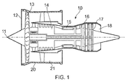
- a gas turbine engine is generally indicated at 10, having a principal and rotational axis 11.
- the engine 10 comprises, in axial flow series, an air intake 12, a propulsive fan 13, a high-pressure compressor 14, combustion equipment 15, a high-pressure turbine 16, a low-pressure turbine 17 and an exhaust nozzle 18.
- a nacelle 20 generally surrounds the engine 10 and defines the intake 12.
- the gas turbine engine 10 works in the conventional manner so that air entering the intake 12 is accelerated by the fan 13 to produce two air flows: a first air flow into the high-pressure compressor 14 and a second air flow which passes through a bypass duct 21 to provide propulsive thrust.
- the high-pressure compressor 14 compresses the air flow directed into it before delivering that air to the combustion equipment 15.
- the air flow is mixed with fuel and the mixture combusted.
- the resultant hot combustion products then expand through, and thereby drive the high and low-pressure turbines 16, 17 before being exhausted through the nozzle 18 to provide additional propulsive thrust.
- the high 16 and low 17 pressure turbines drive respectively the high pressure compressor 14 and the fan 13, each by suitable interconnecting shaft.
- gas turbine engines to which the present disclosure may be applied may have alternative configurations.
- such engines may have an alternative number of interconnecting shafts (e.g. three) and/or an alternative number of compressors and/or turbines.
- the engine may comprise a gearbox provided in the drive train from a turbine to a compressor and/or fan.
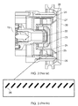
- FIG. 2 shows in more detail a fuel injection system of a type known to be used in the combustion equipment 15 of a gas turbine engine 10.
- a pilot fuel injector 22 is arranged on an axis with annular components coaxially arranged around it.
- Radially adjacent the pilot fuel injector 22 is a pilot air swirler 23.
- a separator 24 bounds the pilot air swirler and further serves as a radially inner wall to a radially outboard main fuel air swirler having radially outer wall 25 and vanes 26 which extend between walls 24 and 25.
- Radially outboard of the main fuel air swirler is an annular main airblast fuel injector 27.
- the atomised air/fuel mixture is delivered to the combustion chamber 30.
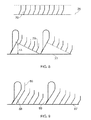
- Figure 3 shows a schematic view of a circumferential wall 25 of the main fuel air swirler and illustrates the arrangement of the vanes thereron.
- Figure 4 shows an air swirler passage wall in accordance with a first embodiment of the invention.
- the wall 35 is made relatively longer in an axial dimension by a length d for part of the circumference.
- the vanes 36 are substantially the same and similarly arranged as the vanes of Figure 3 to provide nominally similar levels of swirl but different local impedances.
- Figure 5 shows an air swirler wall in accordance with a second embodiment of the invention.
- the passage wall 45 is made relatively longer in an axial dimension by a length d along the entire circumference.
- the vanes 46 are substantially the same configuration as those of Figure 3 but are arranged in an axially stepped configuration to provide nominally similar levels of swirl but different local impedances.
- FIG 6 shows an air swirler passage wall in accordance with a third embodiment of the invention.
- the wall 55 is made relatively longer in an axial dimension by a length d along the entire circumference.
- the vanes 56 are individually substantially the same configuration as those of Figure 3 and are similarly arranged.
- Vanes 57 of the second group are longer and spaced further apart to provide nominally similar levels of swirl but different local impedances.
- Figure 7 shows an air swirler wall in accordance with a fourth embodiment of the invention.
- the wall 65 is made relatively longer in an axial dimension along the entire circumference.
- the vanes 66 are consistent in length but are arranged at varying separations e, f, g around the circumference.
- Figure 8 shows an air swirler wall known to be used in a fuel injection system such as that in Figure 1 .
- This figure shows in more detail the shape of pre-swirl vanes 70 which would sit axially upstream of the vanes already discussed.
- the figure provides a comparison for a fifth embodiment of the invention also shown in Figure 8 .
- vanes 76 individually have a similar configuration to those of the prior art arrangement but are grouped and each group is inclined at an angle ⁇ X to a reference circumferential plane 77.
- Figure 9 shows a sixth embodiment of the invention which is broadly similar to the fifth embodiment of Figure 8 .
- the vanes 86 are extended back to the reference circumferential plane 87. It will be appreciated that greater inertia will be effected on the air flow in passage 88 than in passage 89.
- Figure 10 shows a seventh embodiment of the invention wherein the circumferential wall 95 of an air swirler with a radial dimension r is radially stepped to provide two regions 97 and 98 of different radial dimensions R 1 and R 2 .
- Figures 11, 12 and 13 show eighth, ninth and tenth embodiments of the invention.
- the axially downstream facing end of the prefilmer (tip) 29 has been profiled.
- axially extending undulations 101 are provided.
- axially extending serrations are provided.
- an axially extending notch 103 is provided.
- Figure 1 shows cross section views of the prefilmer surface of four pre-filmers which are suited to use in the present invention.
- Prefilmer surface 141 has a continuous radius along its length.
- Prefilmer surface 142 has a scarfed surface with a radius gradually increasing towards the downstream end.
- Prefilmer surface 143 has a concave surface, the radius varying across the surface.
- Prefilmer surface 144 has an undulating surface, the radius varying across the surface.
- a combination of the described features can be implemented around the annulus to reduce coherence and the associated acoustic waves.
- multiple main airblast fuel injector sections are arranged in an annular array as shown in Figure 15 .
- Alternate main airblast fuel injector sections 150 are adapted in accordance with one or more of the previously described embodiments.
- Other main airblast fuel injector sections have a prior art configuration.
Landscapes
- Engineering & Computer Science (AREA)
- Chemical & Material Sciences (AREA)
- Combustion & Propulsion (AREA)
- Mechanical Engineering (AREA)
- General Engineering & Computer Science (AREA)
- Fuel-Injection Apparatus (AREA)
- Structures Of Non-Positive Displacement Pumps (AREA)
Abstract
Description
- This invention concerns fuel injector assemblies for gas turbine engines.
- There is a continuing need, driven by environmental concerns and governmental regulations, for improving the efficiency of and decreasing the emissions from gas turbine engines of the type utilised to power jet aircraft, marine vessels or generate electricity. Particularly there is a continuing drive to reduce oxides of nitrogen (NOx) emissions.
- Advanced gas turbine combustors must meet these requirements for lower NOx emissions under conditions in which the control of NOx generation is very challenging. For example, the goal for the Ultra Efficient Engine Technology (UEET) gas turbine combustor research being done by' NASA is a 70 percent reduction in NOx emissions and a 15 percent improvement in fuel efficiency compared to ICAO 1996 standards technology. Realisation of the fuel efficiency objectives will require an overall cycle pressure ratio as high as 60 to 1 and a peak cycle temperature of 1600 degrees centigrade or greater. The severe combustor pressure and temperature conditions required for improved fuel efficiency make the NOx emissions goal much more difficult to achieve.
- Typical staged low NOx fuel injectors that seek to address this issue have concentrically arranged pilot and main injectors with the main injector surrounding the pilot injector. However, typical staged low NOx injector arrangements have several operational disadvantages, including for example, flame stability and re-light characteristics, the potential for excessive combustor dynamics or pressure fluctuations caused by combustor instability. Combustion instability occurs when the heat release couples with combustor acoustics such that random pressure perturbations in the combustor are amplified into larger pressure oscillations.
- These large pressure oscillations, having amplitudes of about 1-5 percent of the combustor pressure, can have catastrophic consequences and thus must be reduced or eliminated. The phenomenon is sometimes referred to as "rumble".
- There are many suspected causes for rumble but one understood cause is that a pressure wave generated by acoustic resonance in the combustor coherently interacts with an oncoming fuel-air mixture (reactants) from the fuel injector. The reactants feed the combustion flame with a heat release frequency which is coherent with the pressure wave and this can result in a positive growth rate or resonance of the pressure wave and consequently greater noise. In addition to the noise issue, the nature of the interaction of the incident acoustic wave with the reactants is such as to impair characteristics of the reactants and consequently the quality of the combustion.
- In accordance with present invention there is provided a fuel injection system for a gas turbine comprising; a main airblast fuel injector section, the main airblast fuel injector section having an aft end facing a combustion chamber and wherein a surface exposed to air flow through the injection system is non-axisymmetric, or, non-planar in a reference circumferential plane, and configured to generate acoustic impedance at or adjacent the aft end where, in use, the airflow collides with an oncoming acoustic wave.
- The fuel injection system may further comprise a pilot fuel injector section and the surface may be a surface of the pilot fuel injector section.
- Characteristics of the reactants which may affect interaction with an oncoming acoustic wave include; the fuel flux (i.e. the mass flow of the mixture) to the flame, the stoichiometry (i.e. air to fuel ratio), mixture properties such as drop size distribution and droplet dispersion, or the velocity vector of the reactants (fuel placement). Fuel injectors are conventionally designed for a given air and fuel pressure drop but without contemplation of acoustic impedance. The fuel injection system of the present invention addresses the issue of acoustic impedance.
- It will be appreciated that reactants will exit the fuel injection system and encounter oncoming pressure waves from the combustion chamber at the aft end of the main air blast fuel injector system. The provision of a non-axisymmetric surface as described results in a spatially and/or temporarily varied circumferential reaction to the oncoming wave thereby reducing the coherence of the response relative to an axisymmetric/planar design and hence reducing the incidence of acoustic amplification in the chamber.
- Typically, a fuel injector section (which can be a pilot fuel or a main blast fuel injector section) comprises one or more fuel injectors having associated air swirlers which generate swirling, fast moving air for mixing with fuel injected from the fuel injector(s) prior to delivery to a combustion chamber. In accordance with the invention, a surface of an air swirler is made non-axisymmetric or non-planar resulting in a non-axisymmetric distribution of the reactants at the aft end of the main blast fuel injector section where they collide with an oncoming acoustic wave.
- A conventional air swirler comprises at least a pair of coaxially aligned circumferential walls defining an annular channel therebetween. Vanes extend across the channel, optionally engaging with both walls. The walls are conventionally uniformly round with a flat aft end in a plane orthogonal to the axis, the annular channel of uniform width and the vanes are conventionally arranged in radially symmetrical arrays. The vanes may be separated into pre-swirl vanes and swirl vanes, the latter sitting downstream of the former. Pre-swirl vanes in general are bent or curved so as to turn an incoming axial flow tangentially. Swirl vanes are angled relative to an incoming non-axial airstream (having passed through the pre-swirl vanes) and shaped more gently to guide the airstream in a circumferential direction. In embodiments of the present invention, any one or more of these components of the air swirler is adapted to create non-uniformity/a lack of radial symmetry/ a non-planar axially facing surface. In some embodiments of the invention, the transmission of an acoustic wave is affected by adapting an array of swirl vanes in the air swirler. The adapted vane arrangements serve to change the transmission of an acoustic wave by varying the open area between blades and thereby damping the wave.
- In a first embodiment, swirl vanes are arranged in an axially stepped pattern, one or more vanes being arranged along a circumference which is axially displaced from a circumference along which one or more other vanes are arranged. In this embodiment, the vanes may be equally circumferentially spaced and have the same pitch and chord.
- In other embodiments, vanes are arranged along a common circumference but may be unequally spaced. In these embodiments, for a given spacing (pitch) between vanes, the vane size, angle and/or shape may be adapted to preserve the required swirl characteristics for achieving flow structure for good flame anchoring. For example, an array of vanes might comprise a first plurality of vanes with a first length, pitch and thickness and a second plurality of vanes having a second length, pitch and thickness, the first length being shorter than the second length, the first pitch being smaller than the second pitch and the first thickness being greater than the second thickness, or a combination thereof. The first plurality and second plurality may be sub divided into groups, groups of the first plurality being interspersed between groups of the second plurality around the common circumference.
- In an alternative arrangement, groups of similarly configured vanes are arranged with varying pitches around a common circumference. Desirably in these arrangements, the vanes have an elongated chord configured to conserve swirl.
- In yet another embodiment, pre-swirl vanes are elongated whereby to increase inertia in the air stream. The pre swirl vanes may be grouped into a small plurality of pre-swirl vanes having gradually decreasing lengths at an axially downstream end of the vanes. The inertia in passages between adjacent longer vanes is greater than between adjacent shorter length vanes and so results in a varied circumferential flow pattern exiting the fuel injection system and consequent impedance of an oncoming acoustic wave. A similar effect can be achieved by arranging small groups of pre-swirl vanes of similar configuration at an angle to a circumferential reference plane. An incoming air stream will travel further to the most axially distant pre-swirl vanes than to the more proximal vanes and emerge at different times creating a non-axisymmetric flow pattern dynamic response downstream.
- In yet other embodiments, the walls of the air swirler can be adapted. For example, the aft end could be axially stepped rather than flat, thereby impeding a circumferentially uniform oncoming acoustic wave. In another alternative, the radius of one or both walls could be varied adjusting the radial height of the channel around a circumferential reference plane resulting in a non-axisymmetric flow pattern downstream.
- An annular fuel injection section may comprise an annular prefilming surface onto which fuel is dispensed prior to atomisation at the axial tip of the prefilmer by air exiting an adjacent air swirler. An axially downstream facing end of the prefilmer (which defines the tip) is conventionally axisymmetric. In some embodiments of the invention, the tip has a varying axial length. For example, the tip may present axially with an undulating, a crenelated or a serrated profile. The tip profile may have a uniform pattern about the circumference. Alternatively, the tip is provided with a non-uniform pattern of axial notches.
- In another alternative, a radial face of the prefilming surface can be profiled in an axial direction, for example, the surface is undulated concave or convex in cross section.
- In yet another alternative, surfaces of the air swirler walls or prefilmer can be textured to introduce small radial or axially facing variations in the surface which are sufficient to generate an acoustic impedance that locally alters the fuel mixture delivery.
- Embodiments will now be described by way of example only, with reference to the Figures, in which:
-
Figure 1 is a sectional side view of a gas turbine engine; -
Figure 2 is a section through a fuel injection system as is known in the prior art; -
Figure 3 is a schematic plan view of a wall of an air swirler in the fuel injection system ofFigure 2 . -
Figure 3 is a schematic plan view of a wall of an air swirler adapted in accordance with an embodiment of the invention; -
Figure 4 is a schematic plan view of a wall of an air swirler adapted in accordance with another embodiment of the invention; -
Figure 5 is a schematic plan view of a wall of an air swirler adapted in accordance with another embodiment of the invention; -
Figure 6 is a schematic plan view of a wall of an air swirler adapted in accordance with an embodiment of the invention; -
Figure 7 is a schematic plan view of a wall of an air swirler adapted in accordance with another embodiment of the invention; -
Figure 8 is a schematic plan view of a wall of an air swirler in the fuel injection system ofFigure 2 showing the pre-swirler vane geometry; -
Figure 9 is a schematic plan view of a wall of an air swirler adapted in accordance with another embodiment of the invention; -
Figure 10 is a schematic plan view of a wall of an air swirler adapted in accordance with another embodiment of the invention; -
Figure 11 is schematic end view of a section of an axial tip of the prefilmer adapted in accordance with another embodiment of the invention; -
Figure 12 is schematic end view of a section of an axial tip of the prefilmer adapted in accordance with another embodiment of the invention; -
Figure 13 is schematic end view of a section of an axial tip of the prefilmer adapted in accordance with another embodiment of the invention; -
Figure 14 is a schematic view showing examples of profiling of a prefilming surface in an axial direction in accordance with embodiments of the invention. - With reference to
Figure 1 , a gas turbine engine is generally indicated at 10, having a principal and rotational axis 11. The engine 10 comprises, in axial flow series, anair intake 12, apropulsive fan 13, a high-pressure compressor 14,combustion equipment 15, a high-pressure turbine 16, a low-pressure turbine 17 and anexhaust nozzle 18. Anacelle 20 generally surrounds the engine 10 and defines theintake 12. - The gas turbine engine 10 works in the conventional manner so that air entering the
intake 12 is accelerated by thefan 13 to produce two air flows: a first air flow into the high-pressure compressor 14 and a second air flow which passes through abypass duct 21 to provide propulsive thrust. The high-pressure compressor 14 compresses the air flow directed into it before delivering that air to thecombustion equipment 15. - In the
combustion equipment 15 the air flow is mixed with fuel and the mixture combusted. The resultant hot combustion products then expand through, and thereby drive the high and low-pressure turbines 16, 17 before being exhausted through thenozzle 18 to provide additional propulsive thrust. The high 16 and low 17 pressure turbines drive respectively thehigh pressure compressor 14 and thefan 13, each by suitable interconnecting shaft. - Other gas turbine engines to which the present disclosure may be applied may have alternative configurations. By way of example such engines may have an alternative number of interconnecting shafts (e.g. three) and/or an alternative number of compressors and/or turbines. Further the engine may comprise a gearbox provided in the drive train from a turbine to a compressor and/or fan.
-
Figure 2 shows in more detail a fuel injection system of a type known to be used in thecombustion equipment 15 of a gas turbine engine 10. As can be seen apilot fuel injector 22 is arranged on an axis with annular components coaxially arranged around it. Radially adjacent thepilot fuel injector 22 is apilot air swirler 23. Aseparator 24 bounds the pilot air swirler and further serves as a radially inner wall to a radially outboard main fuel air swirler having radiallyouter wall 25 andvanes 26 which extend betweenwalls airblast fuel injector 27. Fuel injected from the mainairblast fuel injector 27 spreads alongprefilmer surface 28 and is atomised at the axial tip of theprefilmer 29 through interaction with air exiting the main fuel air swirler. The atomised air/fuel mixture is delivered to thecombustion chamber 30. -
Figure 3 shows a schematic view of acircumferential wall 25 of the main fuel air swirler and illustrates the arrangement of the vanes thereron. -
Figure 4 shows an air swirler passage wall in accordance with a first embodiment of the invention. In comparison to the air swirler ofFigures 2 and 3 , thewall 35 is made relatively longer in an axial dimension by a length d for part of the circumference. Thevanes 36 are substantially the same and similarly arranged as the vanes ofFigure 3 to provide nominally similar levels of swirl but different local impedances. -
Figure 5 shows an air swirler wall in accordance with a second embodiment of the invention. In comparison to the air swirler ofFigures 2 and 3 , thepassage wall 45 is made relatively longer in an axial dimension by a length d along the entire circumference. Thevanes 46 are substantially the same configuration as those ofFigure 3 but are arranged in an axially stepped configuration to provide nominally similar levels of swirl but different local impedances. -
Figure 6 shows an air swirler passage wall in accordance with a third embodiment of the invention. In comparison to the air swirler ofFigures 2 and 3 , thewall 55 is made relatively longer in an axial dimension by a length d along the entire circumference. There are two groups ofvanes vanes 56 are individually substantially the same configuration as those ofFigure 3 and are similarly arranged.Vanes 57 of the second group are longer and spaced further apart to provide nominally similar levels of swirl but different local impedances. -
Figure 7 shows an air swirler wall in accordance with a fourth embodiment of the invention. In comparison to the air swirler ofFigures 2 and 3 , thewall 65 is made relatively longer in an axial dimension along the entire circumference. Thevanes 66 are consistent in length but are arranged at varying separations e, f, g around the circumference. -
Figure 8 shows an air swirler wall known to be used in a fuel injection system such as that inFigure 1 . This figure shows in more detail the shape ofpre-swirl vanes 70 which would sit axially upstream of the vanes already discussed. The figure provides a comparison for a fifth embodiment of the invention also shown inFigure 8 . In the embodiment,vanes 76 individually have a similar configuration to those of the prior art arrangement but are grouped and each group is inclined at an angle ΔX to areference circumferential plane 77. -
Figure 9 shows a sixth embodiment of the invention which is broadly similar to the fifth embodiment ofFigure 8 . However, in this embodiment thevanes 86 are extended back to thereference circumferential plane 87. It will be appreciated that greater inertia will be effected on the air flow inpassage 88 than inpassage 89. -
Figure 10 shows a seventh embodiment of the invention wherein thecircumferential wall 95 of an air swirler with a radial dimension r is radially stepped to provide tworegions -
Figures 11, 12 and 13 show eighth, ninth and tenth embodiments of the invention. In each of these embodiments, the axially downstream facing end of the prefilmer (tip) 29 has been profiled. InFigure 11 , axially extendingundulations 101 are provided. InFigure 12 , axially extending serrations are provided. InFigure 13 , anaxially extending notch 103 is provided.Figure 1 shows cross section views of the prefilmer surface of four pre-filmers which are suited to use in the present invention.Prefilmer surface 141 has a continuous radius along its length.Prefilmer surface 142 has a scarfed surface with a radius gradually increasing towards the downstream end.Prefilmer surface 143 has a concave surface, the radius varying across the surface.Prefilmer surface 144 has an undulating surface, the radius varying across the surface. A combination of the described features can be implemented around the annulus to reduce coherence and the associated acoustic waves. - In some embodiments of injection fuel systems in accordance with the present invention, multiple main airblast fuel injector sections are arranged in an annular array as shown in
Figure 15 . Alternate main airblastfuel injector sections 150 are adapted in accordance with one or more of the previously described embodiments. Other main airblast fuel injector sections have a prior art configuration. - It will be understood that the invention is not limited to the embodiments above-described and various modifications and improvements can be made without departing from the concepts described herein. Except where mutually exclusive, any of the features may be employed separately or in combination with any other features and the disclosure extends to and includes all combinations and subcombinations of one or more features described herein.
Claims (20)
- A fuel injection system for a gas turbine engine (10) comprising; a main airblast fuel injector section (25, 26, 27, 28, 29), the main airblast fuel injector section having an aft end (29) facing a combustion chamber (30) and wherein a surface exposed to air flow through the injection system is non-axisymmetric, or, non-planar in a reference circumferential plane, and configured to generate acoustic impedance at or adjacent the aft end where, in use, the air flow collides with an oncoming acoustic wave.
- A fuel injection system as claimed in claim further comprising a pilot fuel injector section (22, 23) and wherein the surface is a surface of the pilot fuel injector section.
- A fuel injection system as claimed in claim 1 wherein the exposed surface is a surface of an air swirler (25) or prefilmer (28, 29) of the main airblast fuel injector section.
- A fuel injection system as claimed in claim 1, 2 or 3 wherein the exposed surface is an annular wall of an air swirler (35) and the wall is extended axially along part of its circumference.
- A fuel injection system as claimed in claim 1, 2 or 3 wherein the exposed surface is an annular wall of an air swirler (45) and comprises an annular array of swirl vanes (46) which includes an axial step.
- A fuel injection system as claimed in claim 1, 2 or 3 wherein the exposed surface is an annular wall of an air swirler (55) and an annular array of vanes (56, 57) on the annular wall includes a first plurality of vanes (56) with a first length, pitch and thickness and a second plurality of vanes (57) having a second length, pitch and thickness, the first length being shorter than the second length, the first pitch being smaller than the second pitch and the first thickness being greater than the second thickness.
- A fuel injection system as claimed in claim 6 wherein the first plurality and second plurality are divided into groups, groups of the first plurality being interspersed between groups of the second plurality around a common circumference.
- A fuel injection system as claimed in claim 1, 2 or 3 wherein the exposed surface is an annular wall of an air swirler (65) and an annular array of vanes (66) on the annular wall includes groups of similarly configured vanes arranged with varying pitches (e, f, g) around a common circumference.
- A fuel injection system as claimed in claim 8 wherein the vanes have an elongated chord configured to conserve swirl.
- A fuel injection system as claimed in claim 1, 2 or 3 wherein the exposed surface is an annular wall of an air swirler and an annular array of pre-swirl vanes (76) on the annular wall includes a plurality of grouped vanes of similar configuration arranged along a circumferential reference plane, each group arranged at an angle to the reference plane.
- A fuel injection system as claimed in claim 10 wherein each vane is extended to meet the circumferential reference plane.
- A fuel injection system as claimed in claim 1, 2 or 3 wherein the exposed surface is an annular wall of an air swirler (95) and the wall is provided with a radial step.
- A fuel injection system as claimed in claim 3 wherein the exposed surface is an axially facing tip (29) of a prefilmer and the tip has axially extending undulations (101).
- A fuel injection system in claim 3 wherein the exposed surface is an axially facing tip of a prefilmer and the tip has axially extending serrations (102).
- A fuel injection system in claim 3 wherein the exposed surface is an axially facing tip of a prefilmer and the tip has one or more axially extending notches (103).
- A fuel injection system as claimed in claim 3 wherein the exposed surface is a radially facing wall of a prefilmer (143, 144) and the wall a non-axisymmetric profile.
- A fuel injection system as claimed in claim 16 wherein the non-axisymmetric profile (143) is concave.
- A fuel injection system as claimed in claim 16 or 17 wherein the non-axisymmetric profile (144) is undulated.
- A fuel injection system as claimed in claim 1 comprising an annular array of main airblast fuel injector sections wherein a proportion (150) of the main airblast fuel injector sections (150) are adapted such that a surface exposed to air flow through the injection system is non-axisymmetric, or, non-planar in a reference circumferential plane, and configured to generate acoustic impedance at or adjacent the aft end where, in use, the air flow collides with an oncoming acoustic wave.
- A gas turbine engine incorporating a fuel injection system configured according to any preceding claim.
Applications Claiming Priority (1)
| Application Number | Priority Date | Filing Date | Title |
|---|---|---|---|
| GBGB1512000.9A GB201512000D0 (en) | 2015-07-09 | 2015-07-09 | Fuel injector |
Publications (2)
| Publication Number | Publication Date |
|---|---|
| EP3118519A1 true EP3118519A1 (en) | 2017-01-18 |
| EP3118519B1 EP3118519B1 (en) | 2019-12-25 |
Family
ID=54013691
Family Applications (1)
| Application Number | Title | Priority Date | Filing Date |
|---|---|---|---|
| EP16173682.2A Active EP3118519B1 (en) | 2015-07-09 | 2016-06-09 | Fuel injector |
Country Status (3)
| Country | Link |
|---|---|
| US (2) | US20170009991A1 (en) |
| EP (1) | EP3118519B1 (en) |
| GB (1) | GB201512000D0 (en) |
Families Citing this family (3)
| Publication number | Priority date | Publication date | Assignee | Title |
|---|---|---|---|---|
| TWI555477B (en) * | 2015-12-03 | 2016-11-01 | Taiwan Paiho Ltd | Mushroom Head Shot Hook and Velcro with the Mushroom Head Shot |
| GB201806020D0 (en) | 2018-02-23 | 2018-05-30 | Rolls Royce | Conduit |
| CN116293802B (en) * | 2023-03-14 | 2024-05-14 | 中国空气动力研究与发展中心空天技术研究所 | Super-combustion ramjet engine combustion chamber based on shock wave system ignition and backflow flame stabilization |
Citations (4)
| Publication number | Priority date | Publication date | Assignee | Title |
|---|---|---|---|---|
| WO1999006767A1 (en) * | 1997-07-31 | 1999-02-11 | Siemens Aktiengesellschaft | Burner |
| EP1391653A2 (en) * | 2002-08-21 | 2004-02-25 | Rolls-Royce Plc | Fuel injection arrangement |
| EP1391652A2 (en) * | 2002-08-21 | 2004-02-25 | Rolls-Royce Plc | Fuel injection apparatus |
| EP2554909A2 (en) * | 2011-08-04 | 2013-02-06 | Rolls-Royce plc | Fuel injector |
-
2015
- 2015-07-09 GB GBGB1512000.9A patent/GB201512000D0/en not_active Ceased
-
2016
- 2016-06-09 EP EP16173682.2A patent/EP3118519B1/en active Active
- 2016-06-10 US US15/179,495 patent/US20170009991A1/en not_active Abandoned
-
2019
- 2019-02-28 US US16/288,535 patent/US20190195497A1/en not_active Abandoned
Patent Citations (4)
| Publication number | Priority date | Publication date | Assignee | Title |
|---|---|---|---|---|
| WO1999006767A1 (en) * | 1997-07-31 | 1999-02-11 | Siemens Aktiengesellschaft | Burner |
| EP1391653A2 (en) * | 2002-08-21 | 2004-02-25 | Rolls-Royce Plc | Fuel injection arrangement |
| EP1391652A2 (en) * | 2002-08-21 | 2004-02-25 | Rolls-Royce Plc | Fuel injection apparatus |
| EP2554909A2 (en) * | 2011-08-04 | 2013-02-06 | Rolls-Royce plc | Fuel injector |
Also Published As
| Publication number | Publication date |
|---|---|
| US20190195497A1 (en) | 2019-06-27 |
| US20170009991A1 (en) | 2017-01-12 |
| EP3118519B1 (en) | 2019-12-25 |
| GB201512000D0 (en) | 2015-08-19 |
Similar Documents
| Publication | Publication Date | Title |
|---|---|---|
| CA2845146C (en) | Combustor for gas turbine engine | |
| EP3147571B1 (en) | A fuel injector for a gas turbine engine combustion chamber | |
| US8387393B2 (en) | Flashback resistant fuel injection system | |
| US20120180487A1 (en) | System for flow control in multi-tube fuel nozzle | |
| EP2092240A1 (en) | Fuel injector | |
| US20190170355A1 (en) | Fuel injector | |
| US9127843B2 (en) | Combustor for gas turbine engine | |
| EP2840316B1 (en) | Airblast fuel injector | |
| US11635209B2 (en) | Gas turbine combustor dome with integrated flare swirler | |
| EP2778370B1 (en) | Combustor for gas turbine engine | |
| CA2845164C (en) | Combustor for gas turbine engine | |
| US20190195497A1 (en) | Fuel injector | |
| EP2554909A2 (en) | Fuel injector | |
| US10712008B2 (en) | Combustion chamber and a combustion chamber fuel injector seal | |
| KR102762432B1 (en) | Nozzle assembly, combustor and gas turbine comprising the same | |
| US20240117967A1 (en) | A fuel injector | |
| GB2564913A (en) | A combustion chamber and a combustion chamber fuel injector seal |
Legal Events
| Date | Code | Title | Description |
|---|---|---|---|
| PUAI | Public reference made under article 153(3) epc to a published international application that has entered the european phase |
Free format text: ORIGINAL CODE: 0009012 |
|
| STAA | Information on the status of an ep patent application or granted ep patent |
Free format text: STATUS: THE APPLICATION HAS BEEN PUBLISHED |
|
| AK | Designated contracting states |
Kind code of ref document: A1 Designated state(s): AL AT BE BG CH CY CZ DE DK EE ES FI FR GB GR HR HU IE IS IT LI LT LU LV MC MK MT NL NO PL PT RO RS SE SI SK SM TR |
|
| AX | Request for extension of the european patent |
Extension state: BA ME |
|
| STAA | Information on the status of an ep patent application or granted ep patent |
Free format text: STATUS: REQUEST FOR EXAMINATION WAS MADE |
|
| 17P | Request for examination filed |
Effective date: 20170628 |
|
| RBV | Designated contracting states (corrected) |
Designated state(s): AL AT BE BG CH CY CZ DE DK EE ES FI FR GB GR HR HU IE IS IT LI LT LU LV MC MK MT NL NO PL PT RO RS SE SI SK SM TR |
|
| STAA | Information on the status of an ep patent application or granted ep patent |
Free format text: STATUS: EXAMINATION IS IN PROGRESS |
|
| 17Q | First examination report despatched |
Effective date: 20180622 |
|
| GRAP | Despatch of communication of intention to grant a patent |
Free format text: ORIGINAL CODE: EPIDOSNIGR1 |
|
| STAA | Information on the status of an ep patent application or granted ep patent |
Free format text: STATUS: GRANT OF PATENT IS INTENDED |
|
| GRAJ | Information related to disapproval of communication of intention to grant by the applicant or resumption of examination proceedings by the epo deleted |
Free format text: ORIGINAL CODE: EPIDOSDIGR1 |
|
| STAA | Information on the status of an ep patent application or granted ep patent |
Free format text: STATUS: EXAMINATION IS IN PROGRESS |
|
| GRAP | Despatch of communication of intention to grant a patent |
Free format text: ORIGINAL CODE: EPIDOSNIGR1 |
|
| STAA | Information on the status of an ep patent application or granted ep patent |
Free format text: STATUS: GRANT OF PATENT IS INTENDED |
|
| INTG | Intention to grant announced |
Effective date: 20190820 |
|
| INTC | Intention to grant announced (deleted) | ||
| INTG | Intention to grant announced |
Effective date: 20190912 |
|
| GRAS | Grant fee paid |
Free format text: ORIGINAL CODE: EPIDOSNIGR3 |
|
| GRAA | (expected) grant |
Free format text: ORIGINAL CODE: 0009210 |
|
| STAA | Information on the status of an ep patent application or granted ep patent |
Free format text: STATUS: THE PATENT HAS BEEN GRANTED |
|
| AK | Designated contracting states |
Kind code of ref document: B1 Designated state(s): AL AT BE BG CH CY CZ DE DK EE ES FI FR GB GR HR HU IE IS IT LI LT LU LV MC MK MT NL NO PL PT RO RS SE SI SK SM TR |
|
| REG | Reference to a national code |
Ref country code: GB Ref legal event code: FG4D |
|
| REG | Reference to a national code |
Ref country code: CH Ref legal event code: EP |
|
| REG | Reference to a national code |
Ref country code: DE Ref legal event code: R096 Ref document number: 602016026702 Country of ref document: DE |
|
| REG | Reference to a national code |
Ref country code: AT Ref legal event code: REF Ref document number: 1217499 Country of ref document: AT Kind code of ref document: T Effective date: 20200115 |
|
| REG | Reference to a national code |
Ref country code: IE Ref legal event code: FG4D |
|
| RAP2 | Party data changed (patent owner data changed or rights of a patent transferred) |
Owner name: ROLLS-ROYCE PLC |
|
| REG | Reference to a national code |
Ref country code: NL Ref legal event code: MP Effective date: 20191225 |
|
| PG25 | Lapsed in a contracting state [announced via postgrant information from national office to epo] |
Ref country code: LV Free format text: LAPSE BECAUSE OF FAILURE TO SUBMIT A TRANSLATION OF THE DESCRIPTION OR TO PAY THE FEE WITHIN THE PRESCRIBED TIME-LIMIT Effective date: 20191225 Ref country code: SE Free format text: LAPSE BECAUSE OF FAILURE TO SUBMIT A TRANSLATION OF THE DESCRIPTION OR TO PAY THE FEE WITHIN THE PRESCRIBED TIME-LIMIT Effective date: 20191225 Ref country code: FI Free format text: LAPSE BECAUSE OF FAILURE TO SUBMIT A TRANSLATION OF THE DESCRIPTION OR TO PAY THE FEE WITHIN THE PRESCRIBED TIME-LIMIT Effective date: 20191225 Ref country code: BG Free format text: LAPSE BECAUSE OF FAILURE TO SUBMIT A TRANSLATION OF THE DESCRIPTION OR TO PAY THE FEE WITHIN THE PRESCRIBED TIME-LIMIT Effective date: 20200325 Ref country code: GR Free format text: LAPSE BECAUSE OF FAILURE TO SUBMIT A TRANSLATION OF THE DESCRIPTION OR TO PAY THE FEE WITHIN THE PRESCRIBED TIME-LIMIT Effective date: 20200326 Ref country code: NO Free format text: LAPSE BECAUSE OF FAILURE TO SUBMIT A TRANSLATION OF THE DESCRIPTION OR TO PAY THE FEE WITHIN THE PRESCRIBED TIME-LIMIT Effective date: 20200325 Ref country code: LT Free format text: LAPSE BECAUSE OF FAILURE TO SUBMIT A TRANSLATION OF THE DESCRIPTION OR TO PAY THE FEE WITHIN THE PRESCRIBED TIME-LIMIT Effective date: 20191225 |
|
| REG | Reference to a national code |
Ref country code: LT Ref legal event code: MG4D |
|
| PG25 | Lapsed in a contracting state [announced via postgrant information from national office to epo] |
Ref country code: RS Free format text: LAPSE BECAUSE OF FAILURE TO SUBMIT A TRANSLATION OF THE DESCRIPTION OR TO PAY THE FEE WITHIN THE PRESCRIBED TIME-LIMIT Effective date: 20191225 Ref country code: HR Free format text: LAPSE BECAUSE OF FAILURE TO SUBMIT A TRANSLATION OF THE DESCRIPTION OR TO PAY THE FEE WITHIN THE PRESCRIBED TIME-LIMIT Effective date: 20191225 |
|
| PG25 | Lapsed in a contracting state [announced via postgrant information from national office to epo] |
Ref country code: AL Free format text: LAPSE BECAUSE OF FAILURE TO SUBMIT A TRANSLATION OF THE DESCRIPTION OR TO PAY THE FEE WITHIN THE PRESCRIBED TIME-LIMIT Effective date: 20191225 |
|
| PG25 | Lapsed in a contracting state [announced via postgrant information from national office to epo] |
Ref country code: CZ Free format text: LAPSE BECAUSE OF FAILURE TO SUBMIT A TRANSLATION OF THE DESCRIPTION OR TO PAY THE FEE WITHIN THE PRESCRIBED TIME-LIMIT Effective date: 20191225 Ref country code: RO Free format text: LAPSE BECAUSE OF FAILURE TO SUBMIT A TRANSLATION OF THE DESCRIPTION OR TO PAY THE FEE WITHIN THE PRESCRIBED TIME-LIMIT Effective date: 20191225 Ref country code: PT Free format text: LAPSE BECAUSE OF FAILURE TO SUBMIT A TRANSLATION OF THE DESCRIPTION OR TO PAY THE FEE WITHIN THE PRESCRIBED TIME-LIMIT Effective date: 20200520 Ref country code: NL Free format text: LAPSE BECAUSE OF FAILURE TO SUBMIT A TRANSLATION OF THE DESCRIPTION OR TO PAY THE FEE WITHIN THE PRESCRIBED TIME-LIMIT Effective date: 20191225 Ref country code: EE Free format text: LAPSE BECAUSE OF FAILURE TO SUBMIT A TRANSLATION OF THE DESCRIPTION OR TO PAY THE FEE WITHIN THE PRESCRIBED TIME-LIMIT Effective date: 20191225 |
|
| PG25 | Lapsed in a contracting state [announced via postgrant information from national office to epo] |
Ref country code: SK Free format text: LAPSE BECAUSE OF FAILURE TO SUBMIT A TRANSLATION OF THE DESCRIPTION OR TO PAY THE FEE WITHIN THE PRESCRIBED TIME-LIMIT Effective date: 20191225 Ref country code: IS Free format text: LAPSE BECAUSE OF FAILURE TO SUBMIT A TRANSLATION OF THE DESCRIPTION OR TO PAY THE FEE WITHIN THE PRESCRIBED TIME-LIMIT Effective date: 20200425 Ref country code: SM Free format text: LAPSE BECAUSE OF FAILURE TO SUBMIT A TRANSLATION OF THE DESCRIPTION OR TO PAY THE FEE WITHIN THE PRESCRIBED TIME-LIMIT Effective date: 20191225 |
|
| REG | Reference to a national code |
Ref country code: DE Ref legal event code: R097 Ref document number: 602016026702 Country of ref document: DE |
|
| PG25 | Lapsed in a contracting state [announced via postgrant information from national office to epo] |
Ref country code: DK Free format text: LAPSE BECAUSE OF FAILURE TO SUBMIT A TRANSLATION OF THE DESCRIPTION OR TO PAY THE FEE WITHIN THE PRESCRIBED TIME-LIMIT Effective date: 20191225 Ref country code: ES Free format text: LAPSE BECAUSE OF FAILURE TO SUBMIT A TRANSLATION OF THE DESCRIPTION OR TO PAY THE FEE WITHIN THE PRESCRIBED TIME-LIMIT Effective date: 20191225 |
|
| PLBE | No opposition filed within time limit |
Free format text: ORIGINAL CODE: 0009261 |
|
| STAA | Information on the status of an ep patent application or granted ep patent |
Free format text: STATUS: NO OPPOSITION FILED WITHIN TIME LIMIT |
|
| REG | Reference to a national code |
Ref country code: AT Ref legal event code: MK05 Ref document number: 1217499 Country of ref document: AT Kind code of ref document: T Effective date: 20191225 |
|
| PG25 | Lapsed in a contracting state [announced via postgrant information from national office to epo] |
Ref country code: SI Free format text: LAPSE BECAUSE OF FAILURE TO SUBMIT A TRANSLATION OF THE DESCRIPTION OR TO PAY THE FEE WITHIN THE PRESCRIBED TIME-LIMIT Effective date: 20191225 |
|
| 26N | No opposition filed |
Effective date: 20200928 |
|
| PG25 | Lapsed in a contracting state [announced via postgrant information from national office to epo] |
Ref country code: IT Free format text: LAPSE BECAUSE OF FAILURE TO SUBMIT A TRANSLATION OF THE DESCRIPTION OR TO PAY THE FEE WITHIN THE PRESCRIBED TIME-LIMIT Effective date: 20191225 Ref country code: AT Free format text: LAPSE BECAUSE OF FAILURE TO SUBMIT A TRANSLATION OF THE DESCRIPTION OR TO PAY THE FEE WITHIN THE PRESCRIBED TIME-LIMIT Effective date: 20191225 Ref country code: MC Free format text: LAPSE BECAUSE OF FAILURE TO SUBMIT A TRANSLATION OF THE DESCRIPTION OR TO PAY THE FEE WITHIN THE PRESCRIBED TIME-LIMIT Effective date: 20191225 |
|
| REG | Reference to a national code |
Ref country code: CH Ref legal event code: PL |
|
| PG25 | Lapsed in a contracting state [announced via postgrant information from national office to epo] |
Ref country code: PL Free format text: LAPSE BECAUSE OF FAILURE TO SUBMIT A TRANSLATION OF THE DESCRIPTION OR TO PAY THE FEE WITHIN THE PRESCRIBED TIME-LIMIT Effective date: 20191225 |
|
| PG25 | Lapsed in a contracting state [announced via postgrant information from national office to epo] |
Ref country code: LU Free format text: LAPSE BECAUSE OF NON-PAYMENT OF DUE FEES Effective date: 20200609 |
|
| REG | Reference to a national code |
Ref country code: BE Ref legal event code: MM Effective date: 20200630 |
|
| PG25 | Lapsed in a contracting state [announced via postgrant information from national office to epo] |
Ref country code: IE Free format text: LAPSE BECAUSE OF NON-PAYMENT OF DUE FEES Effective date: 20200609 Ref country code: LI Free format text: LAPSE BECAUSE OF NON-PAYMENT OF DUE FEES Effective date: 20200630 Ref country code: CH Free format text: LAPSE BECAUSE OF NON-PAYMENT OF DUE FEES Effective date: 20200630 |
|
| PG25 | Lapsed in a contracting state [announced via postgrant information from national office to epo] |
Ref country code: BE Free format text: LAPSE BECAUSE OF NON-PAYMENT OF DUE FEES Effective date: 20200630 |
|
| PG25 | Lapsed in a contracting state [announced via postgrant information from national office to epo] |
Ref country code: TR Free format text: LAPSE BECAUSE OF FAILURE TO SUBMIT A TRANSLATION OF THE DESCRIPTION OR TO PAY THE FEE WITHIN THE PRESCRIBED TIME-LIMIT Effective date: 20191225 Ref country code: MT Free format text: LAPSE BECAUSE OF FAILURE TO SUBMIT A TRANSLATION OF THE DESCRIPTION OR TO PAY THE FEE WITHIN THE PRESCRIBED TIME-LIMIT Effective date: 20191225 Ref country code: CY Free format text: LAPSE BECAUSE OF FAILURE TO SUBMIT A TRANSLATION OF THE DESCRIPTION OR TO PAY THE FEE WITHIN THE PRESCRIBED TIME-LIMIT Effective date: 20191225 |
|
| PG25 | Lapsed in a contracting state [announced via postgrant information from national office to epo] |
Ref country code: MK Free format text: LAPSE BECAUSE OF FAILURE TO SUBMIT A TRANSLATION OF THE DESCRIPTION OR TO PAY THE FEE WITHIN THE PRESCRIBED TIME-LIMIT Effective date: 20191225 |
|
| P01 | Opt-out of the competence of the unified patent court (upc) registered |
Effective date: 20230528 |
|
| PGFP | Annual fee paid to national office [announced via postgrant information from national office to epo] |
Ref country code: FR Payment date: 20230622 Year of fee payment: 8 Ref country code: DE Payment date: 20230627 Year of fee payment: 8 |
|
| PGFP | Annual fee paid to national office [announced via postgrant information from national office to epo] |
Ref country code: GB Payment date: 20230620 Year of fee payment: 8 |
|
| REG | Reference to a national code |
Ref country code: DE Ref legal event code: R119 Ref document number: 602016026702 Country of ref document: DE |
|
| GBPC | Gb: european patent ceased through non-payment of renewal fee |
Effective date: 20240609 |
|
| PG25 | Lapsed in a contracting state [announced via postgrant information from national office to epo] |
Ref country code: DE Free format text: LAPSE BECAUSE OF NON-PAYMENT OF DUE FEES Effective date: 20250101 |
|
| PG25 | Lapsed in a contracting state [announced via postgrant information from national office to epo] |
Ref country code: FR Free format text: LAPSE BECAUSE OF NON-PAYMENT OF DUE FEES Effective date: 20240630 |
|
| PG25 | Lapsed in a contracting state [announced via postgrant information from national office to epo] |
Ref country code: GB Free format text: LAPSE BECAUSE OF NON-PAYMENT OF DUE FEES Effective date: 20240609 |