EP3118494A1 - Seal device - Google Patents
Seal device Download PDFInfo
- Publication number
- EP3118494A1 EP3118494A1 EP15758058.0A EP15758058A EP3118494A1 EP 3118494 A1 EP3118494 A1 EP 3118494A1 EP 15758058 A EP15758058 A EP 15758058A EP 3118494 A1 EP3118494 A1 EP 3118494A1
- Authority
- EP
- European Patent Office
- Prior art keywords
- annular projection
- rotary shaft
- main lip
- annular
- slidable contact
- Prior art date
- Legal status (The legal status is an assumption and is not a legal conclusion. Google has not performed a legal analysis and makes no representation as to the accuracy of the status listed.)
- Granted
Links
Images



Classifications
-
- F—MECHANICAL ENGINEERING; LIGHTING; HEATING; WEAPONS; BLASTING
- F16—ENGINEERING ELEMENTS AND UNITS; GENERAL MEASURES FOR PRODUCING AND MAINTAINING EFFECTIVE FUNCTIONING OF MACHINES OR INSTALLATIONS; THERMAL INSULATION IN GENERAL
- F16J—PISTONS; CYLINDERS; SEALINGS
- F16J15/00—Sealings
- F16J15/002—Sealings comprising at least two sealings in succession
- F16J15/008—Sealings comprising at least two sealings in succession with provision to put out of action at least one sealing; One sealing sealing only on standstill; Emergency or servicing sealings
-
- F—MECHANICAL ENGINEERING; LIGHTING; HEATING; WEAPONS; BLASTING
- F16—ENGINEERING ELEMENTS AND UNITS; GENERAL MEASURES FOR PRODUCING AND MAINTAINING EFFECTIVE FUNCTIONING OF MACHINES OR INSTALLATIONS; THERMAL INSULATION IN GENERAL
- F16J—PISTONS; CYLINDERS; SEALINGS
- F16J15/00—Sealings
- F16J15/16—Sealings between relatively-moving surfaces
- F16J15/32—Sealings between relatively-moving surfaces with elastic sealings, e.g. O-rings
- F16J15/3204—Sealings between relatively-moving surfaces with elastic sealings, e.g. O-rings with at least one lip
- F16J15/3232—Sealings between relatively-moving surfaces with elastic sealings, e.g. O-rings with at least one lip having two or more lips
-
- Y—GENERAL TAGGING OF NEW TECHNOLOGICAL DEVELOPMENTS; GENERAL TAGGING OF CROSS-SECTIONAL TECHNOLOGIES SPANNING OVER SEVERAL SECTIONS OF THE IPC; TECHNICAL SUBJECTS COVERED BY FORMER USPC CROSS-REFERENCE ART COLLECTIONS [XRACs] AND DIGESTS
- Y10—TECHNICAL SUBJECTS COVERED BY FORMER USPC
- Y10S—TECHNICAL SUBJECTS COVERED BY FORMER USPC CROSS-REFERENCE ART COLLECTIONS [XRACs] AND DIGESTS
- Y10S277/00—Seal for a joint or juncture
- Y10S277/91—O-ring seal
Definitions
- the present invention relates to a sealing device for, for example, partitioning an annular space between a rotary shaft and a housing surrounding the rotary shaft, into an atmospheric pressure space and a vacuum space.
- a rotary shaft for rotational force transmission may be provided so as to project from the inside of the vacuum container to the outside thereof.
- a sealing device is mounted in the annular space (see e.g., PATENT LITERATURE 1).
- PATENT LITERATURE 1 Japanese Laid-Open Patent Publication JP 2001-099 328 A
- a seal lip of the sealing device which is in slidable contact with the rotary shaft to seal between the inside and the outside of the vacuum container may be pressed excessively against the rotary shaft by the difference in pressure between the inside and the outside of the vacuum container in addition to an interference that is provided beforehand. If the seal lip is pressed excessively against the rotary shaft as described above, wear of the seal lip is accelerated, so that there is a possibility that the sealing performance of the sealing device deteriorates early and the service life of the sealing device is significantly reduced.
- the present invention has been made in view of such a situation, and an object of the present invention is to provide a sealing device which is able to maintain sealing performance over a long period of time.
- the present invention for achieving the above-described object is a sealing device which partitions an annular space formed between a rotary shaft and a housing surrounding the rotary shaft, into a low-pressure space and a high-pressure space whose pressure is higher than that of the low-pressure space, in an axial direction, the sealing device including an annular seal portion formed of an elastic material and being in slidable contact with an outer peripheral surface of the rotary shaft, wherein: on an inner peripheral surface of the seal portion, a main lip is formed so as to be in slidable contact with the outer peripheral surface of the rotary shaft, and an inclined surface is formed so as to extend from the main lip toward the low-pressure space side and gradually enlarge in diameter toward the low-pressure space side; on the inclined surface, a first annular projection is formed so as to be in slidable contact with the outer peripheral surface of the rotary shaft in a state where the main lip is in slidable contact with the outer peripheral surface of the rotary shaft, and a second annular projection is formed so as
- the sealing device configured as described above, when the sealing device is in the initial use state, required sealing performance is ensured by the main lip and the first annular projection. After that, even when the sealing device is used and the main lip and the first annular projection wear, due to slidable contact thereof with the outer peripheral surface of the rotary shaft, to such a degree that required sealing performance cannot be maintained, the second annular projection starts slidable contact with the outer peripheral surface of the rotary shaft. Thus, the second annular projection can be caused to newly contribute to ensuring sealing performance, and required sealing performance can be maintained.
- sealing device of the present invention even when, due to wear caused by use, it becomes difficult to maintain required sealing performance by the main lip and the first annular projection, required sealing performance as the sealing device can be maintained by newly bringing the second annular projection that has not been in slidable contact, into slidable contact with the outer peripheral surface of the rotary shaft. As a result, it is possible to maintain the sealing performance over a long period of time.
- a plurality of the second annular projections are preferably formed.
- the plurality of the second annular projections are preferably formed such that, when the main lip and the first annular projection wear to such a degree that required sealing performance cannot be maintained, slidable contact is started in order from the second annular projection closer to the main lip, among the plurality of the second annular projections, in accordance with an amount of the wear.
- a third annular projection may be further formed on the inclined surface and between the main lip and the second annular projection so as to be in slidable contact with the outer peripheral surface of the rotary shaft when the sealing device is in the initial use state.
- a space between the low-pressure space and the high-pressure space can be partitioned in multiple stages by the main lip, the first annular projection, and the third annular projection. Accordingly, even when leak of the pressure from the high-pressure space side occurs, it is possible to reduce the leak in a phased manner. Thus, it is possible to maintain the sealing performance ensured in the initial use state before the second annular projection starts slidable contact, over a long period of time.
- the sealing device of the present invention it is possible to maintain the sealing performance over a long period of time.
- FIG. 1 is a cross-sectional view of a sealing device according to an embodiment of the present invention.
- the sealing device 1 is mounted to a vacuum container (not shown) whose interior is made into a vacuum environment.
- the sealing device 1 is used for partitioning an annular space T formed between a rotary shaft S and a housing H surrounding the rotary shaft S, into an atmospheric pressure space A (a high-pressure space, the left side of the sheet surface in FIG. 1 ) and a vacuum space V (a low-pressure space, the right side of the sheet surface in FIG. 1 ) in an axial direction, in a sealed state.
- A a high-pressure space, the left side of the sheet surface in FIG. 1
- V a low-pressure space, the right side of the sheet surface in FIG. 1
- the vacuum space V is maintained in a high vacuum of 10 -3 Pa (absolute pressure) or lower.
- the rotary shaft S is a rotation transmission shaft for providing a rotational force to a device provided within the vacuum container.
- the rotary shaft S is inserted through the tubular housing H which is provided to the vacuum container and provides communication between the inside and the outside of the vacuum container, so that the rotary shaft S is provided so as to project from the vacuum space V which is the inside of the vacuum container toward the atmospheric pressure space A which is the outside of the vacuum container.
- the sealing device 1 partitions the annular space T in an axial direction such that the rotary shaft S is rotatable.
- the sealing device 1 includes a core metal 2 made of a metal, and a seal member 3 which is formed of an elastic material such as fluorocarbon rubber and bonded by vulcanization to the core metal 2.
- the core metal 2 is formed in an annular shape by pressing a steel plate such as SPCC.
- the core metal 2 includes a cylindrical portion 2a having a cylindrical shape, and an annular portion 2b formed by bending an end portion, at one side in the axial direction, of the cylindrical portion 2a to a radially inner side.
- the core metal 2 is formed so as to have an L cross-sectional shape.
- the seal member 3 includes: a body portion 4 which is formed and bonded so as to extend from the outer peripheral surface of the cylindrical portion 2a around an end surface, at the atmospheric pressure space A side, of the cylindrical portion 2a, extend along the inner peripheral surface of the cylindrical portion 2a, and extend along a side surface, at the atmospheric pressure space A side, of the annular portion 2b; a seal portion 5 extending from the inner peripheral end of the annular portion 2b; and an auxiliary lip 7 similarly extending from the inner peripheral end of the annular portion 2b.
- the core metal 2 is press-fitted into the housing H via the body portion 4. Accordingly, the sealing device 1 is fixed to the housing H.
- the auxiliary lip 7 is provided so as to extend from the inner peripheral end of the annular portion 2b as a base end toward the vacuum space V side and project toward the radially inner side to be in slidable contact with an outer peripheral surface S1 of the rotary shaft S.
- the seal portion 5 is an annular member extending from the inner peripheral end of the annular portion 2b as a base end toward the atmospheric pressure space A side.
- a garter spring 8 for enhancing the sealing performance by tightening and pressing the seal portion 5 toward the radially inner side is mounted at the outer peripheral surface side of the seal portion 5.
- the seal portion 5 is in slidable contact with the outer peripheral surface S 1 of the rotary shaft S, sealing between the vacuum space T and the atmospheric pressure space A so as to prevent the pressure of the atmospheric pressure space A from leaking through between the rotary shaft S and the housing H to the vacuum space V.
- a main lip 10 is formed so as to be in slidable contact with the outer peripheral surface S 1 of the rotary shaft S, a vacuum space side inclined surface 11 is formed so as to extend from the main lip 10 toward the vacuum space V side and gradually enlarge in diameter toward the vacuum space V side, and an atmospheric space side inclined surface 12 is formed so as to extend from the main lip 10 toward the atmospheric pressure space A side and gradually enlarge in diameter toward the atmospheric pressure space A side.
- the main lip 10 is composed of a ridge at which the vacuum space side inclined surface 11 and the atmospheric space side inclined surface 12 intersect each other, and is formed so as to have a mountain-like cross-sectional shape.
- the seal portion 5 extends from the inner peripheral end of the annular portion 2b as a base end toward the atmospheric pressure space A side as described above. Therefore, the seal portion 5 is configured such that the end portion thereof at the atmospheric pressure space A side can oscillate about the end portion thereof at the vacuum space V side in the radial direction.
- FIG. 1 shows the seal portion 5 that is in a free state.
- the end portion, at the atmospheric pressure space A side, of the seal portion 5 oscillates toward a radially outer side, and the end portion, at the atmospheric pressure space A side, and the main lip 10, of the seal portion 5 elastically deform so as to slightly enlarge in diameter.
- the main lip 10 is in slidable contact with the outer peripheral surface S 1 of the rotary shaft S in a state where the main lip 10 elastically deforms so as to slightly enlarge in diameter.
- FIG. 2 is an enlarged cross-sectional view of a main part of the seal portion 5 in FIG. 1 .
- FIG. 2 shows the seal portion 5 that is in a free state.
- the vacuum space side inclined surface 11 of the seal portion 5 is formed as a conical inner peripheral surface whose inclination angle d relative to the axial direction is set, for example, in a range of 10° to 20°.
- a first annular projection 20 is formed so as to project from the vacuum space side inclined surface 11 toward the radially inner side.
- a second annular projection 21 is formed between the main lip 10 and the first annular projection 20 so as to project from the vacuum space side inclined surface 11 toward the radially inner side similarly to the first annular projection 20.
- a third annular projection 22 is formed between the main lip 10 and the second annular projection 21 so as to project from the vacuum space side inclined surface 11 toward the radially inner side.
- Each of the annular projections 20 to 22 is formed such that a distal end thereof has a circular arc cross-sectional shape.
- the second annular projection 21 and the third annular projection 22 are formed such that projection dimensions thereof based on the vacuum space side inclined surface 11 are projection dimensions t1 that are equal to each other.
- the first annular projection 20 is formed such that a projection dimension t2 thereof is a value larger than the projection dimension t1 of each of the second annular projection 21 and the third annular projection 22 (e.g., approximately 2 to 3 times of t1).
- the projection dimension t2 of the first annular projection 20 is set to such a value that, as described later, when the sealing device 1 is inserted into the rotary shaft S such that the main lip 10 (and the third annular projection 22) is in slidable contact with the outer peripheral surface S1, the distal end of the first annular projection 20 is in slidable contact with the outer peripheral surface S1.
- the projection dimension t1 of the second annular projection 21 is set to such a value that: when the sealing device 1 is in an initial use state, the second annular projection 21 is not in slidable contact with the outer peripheral surface S1 of the rotary shaft S; and when the main lip 10 and the first annular projection 20 wear due to use, the second annular projection 21 starts slidable contact with the outer peripheral surface S1 of the rotary shaft S.
- the initial use state of the sealing device 1 refers to a state immediately after the sealing device 1 that has not been used is fixed to the housing H and use of the sealing device 1 is started, the state being a state where wear of the main lip 10 and the first annular projection 20 is not observed.
- FIG. 3 is cross-sectional views of the main lip 10 when the rotary shaft S is inserted into the inner peripheral side of the sealing device 1.
- FIG. 3(a) shows the initial use state of the sealing device 1.
- the end portion, at the atmospheric pressure space A side, of the seal portion 5 oscillates about the end portion, at the vacuum space V side, of the seal portion 5 toward the radially outer side.
- the main lip 10 is in slidable contact with the outer peripheral surface S 1 of the rotary shaft S in a state where the main lip 10 elastically deforms so as to slightly enlarge in diameter.
- the inclination angle d ( FIG. 2 ) of the vacuum space side inclined surface 11 decreases as a result of the oscillation of the end portion, at the atmospheric pressure space A side, of the seal portion 5 toward the radially outer side.
- the vacuum space side inclined surface 11 comes close to the outer peripheral surface S 1 of the rotary shaft S.
- the distal end of the first annular projection 20 comes into slidable contact with the outer peripheral surface S 1 of the rotary shaft S. That is, the first annular projection 20 is formed such that the distal end thereof is in slidable contact with the outer peripheral surface S 1 in a state where the main lip 10 is in slidable contact with the outer peripheral surface S 1 of the rotary shaft S.
- the third annular projection 22 is also formed such that the distal end thereof is in slidable contact with the outer peripheral surface S 1 in a state where the main lip 10 is in slidable contact with the outer peripheral surface S1 of the rotary shaft S.
- Each of the main lip 10, the first annular projection 20, and the third annular projection 22 is formed such that an inner diameter dimension thereof when the seal portion 5 is in a free state is a predetermined dimension smaller than the outer diameter dimension of the rotary shaft S.
- the second annular projection 21 is formed such that the inner diameter dimension thereof when the main lip 10, the first annular projection 20, and the third annular projection 22 are brought into slidable contact with the outer peripheral surface S 1 of the rotary shaft S is larger than the diameter of the outer peripheral surface S 1 of the rotary shaft S.
- the second annular projection 21 is not in contact with the outer peripheral surface S1 of the rotary shaft S.
- the second annular projection 21 is formed such that the second annular projection 21 is not in slidable contact with the outer peripheral surface S 1 of the rotary shaft S when the sealing device 1 is in the initial use state and in a state where the main lip 10, the first annular projection 20, and the third annular projection 22 have not worn much.
- the sealing device 1 when the sealing device 1 is in the initial use state, the sealing device 1 seals between the atmospheric pressure space A and the vacuum space V by the main lip 10, the first annular projection 20, and the third annular projection 22.
- FIG. 3(b) is a cross-sectional view of the main lip 10 when the rotary shaft S is inserted into the inner peripheral side of the sealing device 1, and shows a state where the main lip 10, the first annular projection 20, and the third annular projection 22 have worn as a result of the sealing device 1 being used over a long period of time.
- the projection dimensions of the first annular projection 20 and the third annular projection 22 which project from the vacuum space side inclined surface 11 have decreased relative to the second annular projection 21 due to the wear. Accordingly, the second annular projection 21 is in slidable contact with the outer peripheral surface S1 of the rotary shaft S.
- the projection dimension of the second annular projection 21 from the vacuum space side inclined surface 11 is set to such a value that, when the main lip 10, the first annular projection 20, and the third annular projection 22 wear to such a degree that required sealing performance as the sealing device 1 cannot be maintained, the second annular projection 21 comes into slidable contact with the outer peripheral surface S1 of the rotary shaft S.
- the second annular projection 21 is formed such that: when the sealing device 1 is in the initial use state, the second annular projection 21 is not in slidable contact with the outer peripheral surface S1 of the rotary shaft S; and, after that, when the main lip 10, the first annular projection 20, and the third annular projection 22 wear to such a degree that required sealing performance cannot be maintained, the second annular projection 21 starts slidable contact with the outer peripheral surface S1 of the rotary shaft S.
- a space between the vacuum space V and the atmospheric pressure space A can be partitioned in multiple stages (four stages) by four portions, that is, the main lip 10, the first annular projection 20, the third annular projection 22, and the second annular projection 21.
- the projection dimension of the second annular projection 21 from the vacuum space side inclined surface 11 is set to the projection dimension t1, which is equal to that of the third annular projection 22, as described above.
- the dimension of each portion including the setting of the projection dimension t2 of the first annular projection 20 is set such that: when the sealing device 1 is in the initial use state, the second annular projection 21 is not in slidable contact with the outer peripheral surface S 1 of the rotary shaft S; and, after that, when each portion wears to such a degree that required sealing performance cannot be maintained, the second annular projection 21 starts slidable contact with the outer peripheral surface S1 of the rotary shaft S.
- the sealing device 1 configured as described above, when the sealing device 1 is in the initial use state, required sealing performance is ensured by the main lip 10, the first annular projection 20, and the third annular projection 22. After that, even when the sealing device 1 is used and the main lip 10, the first annular projection 20, and the third annular projection 22 wear, due to slidable contact thereof with the outer peripheral surface S 1 of the rotary shaft S, to such a degree that required sealing performance cannot be maintained, the second annular projection 21 starts slidable contact with the outer peripheral surface S1 of the rotary shaft S. Thus, the second annular projection can be caused to newly contribute to ensuring sealing performance, and required sealing performance can be maintained.
- the sealing device 1 of the present invention even when, due to wear caused by use, it becomes difficult to maintain required sealing performance by the main lip 10, the first annular projection 20, and the third annular projection 22, required sealing performance as the sealing device 1 can be maintained by newly bringing the second annular projection 21 that has not being in slidable contact, into slidable contact with the outer peripheral surface S1 of the rotary shaft S. As a result, it is possible to maintain the sealing performance over a long period of time.
- the third annular projection 22 is formed on the vacuum space side inclined surface 11 and between the main lip 10 and the second annular projection 21 so as to be in slidable contact with the outer peripheral surface S 1 of the rotary shaft S when the sealing device 1 is in the initial use state, when the sealing device 1 is in the initial use state, the space between the vacuum space V and the atmospheric pressure space A can be partitioned in multiple stages (three stages) by the main lip 10, the first annular projection 20, and the third annular projection 22.
- the respective annular projections 20 to 22 form a plurality of annular spaces between the respective annular projections 20 to 22 and the adjacent annular projections or the main lip 10. It is possible to cause a lubricant supplied between the main lip 10 and the rotary shaft S, to remain in these annular spaces. That is, when the sealing device 1 is in the initial use state, a plurality of annular spaces can be formed by the main lip 10, the first annular projection 20, and the third annular projection 22 and caused to function as an oil reservoir.
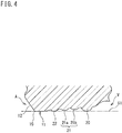
- FIG. 4 is a cross-sectional view of a main lip 10 according to another embodiment of the present invention, and shows the initial use state of the sealing device 1.
- the main lip 10 of the present embodiment is different from that of the above embodiment in that a plurality of second annular projections 21 (two in the shown example) are formed.
- the plurality of second annular projections 21 a, 21b are not in contact with the outer peripheral surface S1 of the rotary shaft S.
- the second annular projection 21 a at the main lip 10 side is formed such that the inner diameter dimension thereof when the main lip 10 and the first annular projection 20 are brought into slidable contact with the rotary shaft S is smaller than that of the second annular projection 21b at the first annular projection 20 side.
- the sealing device 1 when the sealing device 1 is used and wear of the main lip 10, the first annular projection 20, and the third annular projection 22 proceeds due to slidable contact thereof with the outer peripheral surface S 1 of the rotary shaft S, the second annular projection 21a at the main lip 10 side initially starts slidable contact with the outer peripheral surface S1 of the rotary shaft S.
- the plurality of second annular projections 21a and 21b are formed such that slidable contact is started in order from the second annular projection 21 a at the main lip 10 side closer to the main lip 10, among the plurality of second annular projections 21a and 21b, in accordance with the amounts of wear of the main lip 10, the first annular projection 20, and the third annular projection 22.
- the projection dimension of each of the second annular projections 21a and 21b from the vacuum space side inclined surface 11 in the present embodiment is set to the projection dimension t1 ( FIG. 2 ), which is the equal to that of the third annular projection 22.
- the second annular projections 21a and 21b are formed along the vacuum space side inclined surface 11 which gradually enlarges in diameter toward the vacuum space V side.
- the second annular projections 21a and 21b are formed with the projection dimensions t1 that are equal to each other, the second annular projection 21a at the main lip 10 is formed such that the inner diameter dimension thereof when the main lip 10 and the first annular projection 20 are brought into slidable contact with the rotary shaft S is smaller than that of the second annular projection 21b at the first annular projection 20 side.
- the second annular projection 21b since the plurality of second annular projections 21a and 21b start slidable contact in order in accordance with the amounts of wear of the main lip 10, the first annular projection 20, and the third annular projection 22, even when wear of the main lip 10, the first annular projection 20, and the third annular projection 22 proceeds and the second annular projection 21a that has started slidable contact wears later, the second annular projection 21b sequentially and newly starts slidable contact. Accordingly, it is possible to maintain the sealing performance over a further long period of time.
- the plurality of second annular projections 21a and 21b may be formed such that the inner diameter dimensions thereof when the main lip 10 and the first annular projection 20 are brought into slidable contact with the rotary shaft S are equal to each other.
- the present invention is not limited to the above embodiments.
- the case has been shown where the third annular projection 22 is formed between the main lip 10 and the second annular projection 21.
- the second annular projection 21 may be formed between the main lip 10 and the first annular projection 20 as shown in FIG. 5 .
Landscapes
- Engineering & Computer Science (AREA)
- General Engineering & Computer Science (AREA)
- Mechanical Engineering (AREA)
- Sealing With Elastic Sealing Lips (AREA)
- Sealing Devices (AREA)
Abstract
Description
- The present invention relates to a sealing device for, for example, partitioning an annular space between a rotary shaft and a housing surrounding the rotary shaft, into an atmospheric pressure space and a vacuum space.
- Hitherto, in order to provide a rotational force to a device within a vacuum container whose inner space is made a vacuum, a rotary shaft for rotational force transmission may be provided so as to project from the inside of the vacuum container to the outside thereof.
- In this case, in order to maintain a vacuum state by preventing atmospheric air from leaking from an annular space between the rotary shaft and a through hole, which is provided in the vacuum container for inserting the rotary shaft therethrough, into the vacuum container, a sealing device is mounted in the annular space (see e.g., PATENT LITERATURE 1).
- PATENT LITERATURE 1: Japanese Laid-Open Patent Publication
JP 2001-099 328 A - In the above sealing device, a seal lip of the sealing device which is in slidable contact with the rotary shaft to seal between the inside and the outside of the vacuum container may be pressed excessively against the rotary shaft by the difference in pressure between the inside and the outside of the vacuum container in addition to an interference that is provided beforehand. If the seal lip is pressed excessively against the rotary shaft as described above, wear of the seal lip is accelerated, so that there is a possibility that the sealing performance of the sealing device deteriorates early and the service life of the sealing device is significantly reduced.
- The present invention has been made in view of such a situation, and an object of the present invention is to provide a sealing device which is able to maintain sealing performance over a long period of time.
- The present invention for achieving the above-described object is a sealing device which partitions an annular space formed between a rotary shaft and a housing surrounding the rotary shaft, into a low-pressure space and a high-pressure space whose pressure is higher than that of the low-pressure space, in an axial direction, the sealing device including an annular seal portion formed of an elastic material and being in slidable contact with an outer peripheral surface of the rotary shaft, wherein: on an inner peripheral surface of the seal portion, a main lip is formed so as to be in slidable contact with the outer peripheral surface of the rotary shaft, and an inclined surface is formed so as to extend from the main lip toward the low-pressure space side and gradually enlarge in diameter toward the low-pressure space side; on the inclined surface, a first annular projection is formed so as to be in slidable contact with the outer peripheral surface of the rotary shaft in a state where the main lip is in slidable contact with the outer peripheral surface of the rotary shaft, and a second annular projection is formed so as to be disposed between the main lip and the first annular projection and project toward a radially inward side; and the second annular projection is formed such that: when the sealing device is in an initial use state, the second annular projection is not in slidable contact with the outer peripheral surface of the rotary shaft; and when the main lip and the first annular projection wear, due to use of the sealing device, to such a degree that required sealing performance cannot be maintained, the second annular projection starts slidable contact with the outer peripheral surface of the rotary shaft.
- According to the sealing device configured as described above, when the sealing device is in the initial use state, required sealing performance is ensured by the main lip and the first annular projection. After that, even when the sealing device is used and the main lip and the first annular projection wear, due to slidable contact thereof with the outer peripheral surface of the rotary shaft, to such a degree that required sealing performance cannot be maintained, the second annular projection starts slidable contact with the outer peripheral surface of the rotary shaft. Thus, the second annular projection can be caused to newly contribute to ensuring sealing performance, and required sealing performance can be maintained.
- As described above, according to the sealing device of the present invention, even when, due to wear caused by use, it becomes difficult to maintain required sealing performance by the main lip and the first annular projection, required sealing performance as the sealing device can be maintained by newly bringing the second annular projection that has not been in slidable contact, into slidable contact with the outer peripheral surface of the rotary shaft. As a result, it is possible to maintain the sealing performance over a long period of time.
- In the sealing device, a plurality of the second annular projections are preferably formed. In this case, the plurality of the second annular projections are preferably formed such that, when the main lip and the first annular projection wear to such a degree that required sealing performance cannot be maintained, slidable contact is started in order from the second annular projection closer to the main lip, among the plurality of the second annular projections, in accordance with an amount of the wear.
- In this case, since the plurality of the second annular projections start slidable contact in order in accordance with the amounts of wear of the main lip and the first annular projection, wear of the main lip and the first annular projection proceeds. After that, even when one second annular projection that has started slidable contact starts wearing, another second annular projection sequentially and newly starts slidable contact. Accordingly, it is possible to maintain the sealing performance over a further long period of time.
- In the sealing device, a third annular projection may be further formed on the inclined surface and between the main lip and the second annular projection so as to be in slidable contact with the outer peripheral surface of the rotary shaft when the sealing device is in the initial use state.
- In this case, when the sealing device is in the initial use state, a space between the low-pressure space and the high-pressure space can be partitioned in multiple stages by the main lip, the first annular projection, and the third annular projection. Accordingly, even when leak of the pressure from the high-pressure space side occurs, it is possible to reduce the leak in a phased manner. Thus, it is possible to maintain the sealing performance ensured in the initial use state before the second annular projection starts slidable contact, over a long period of time.
- According to the sealing device of the present invention, it is possible to maintain the sealing performance over a long period of time.
-
-
FIG. 1 is a cross-sectional view of a sealing device according to an embodiment of the present invention. -
FIG. 2 is an enlarged cross-sectional view of a main part of a seal portion inFIG. 1 . -
FIG. 3 is cross-sectional views of a main lip when a rotary shaft is inserted into the inner peripheral side of the sealing device, wherein -
FIG. 3(a) shows an initial use state of the sealing device, and -
FIG. 3(b) shows a state where the main lip, a first annular projection, and a third annular projection have worn as a result of use of the sealing device. -
FIG. 4 is a cross-sectional view of a main lip according to another embodiment of the present invention and shows an initial use state of asealing device 1. -
FIG. 5 is a cross-sectional view of a main lip according to still another embodiment of the present invention. - Next, preferred embodiments of the present invention will be described with reference to the accompanying drawings.
-
FIG. 1 is a cross-sectional view of a sealing device according to an embodiment of the present invention. Thesealing device 1 is mounted to a vacuum container (not shown) whose interior is made into a vacuum environment. Thesealing device 1 is used for partitioning an annular space T formed between a rotary shaft S and a housing H surrounding the rotary shaft S, into an atmospheric pressure space A (a high-pressure space, the left side of the sheet surface inFIG. 1 ) and a vacuum space V (a low-pressure space, the right side of the sheet surface inFIG. 1 ) in an axial direction, in a sealed state. - In the present embodiment, the vacuum space V is maintained in a high vacuum of 10-3 Pa (absolute pressure) or lower.
- The rotary shaft S is a rotation transmission shaft for providing a rotational force to a device provided within the vacuum container. The rotary shaft S is inserted through the tubular housing H which is provided to the vacuum container and provides communication between the inside and the outside of the vacuum container, so that the rotary shaft S is provided so as to project from the vacuum space V which is the inside of the vacuum container toward the atmospheric pressure space A which is the outside of the vacuum container.
- The
sealing device 1 partitions the annular space T in an axial direction such that the rotary shaft S is rotatable. Thesealing device 1 includes acore metal 2 made of a metal, and a seal member 3 which is formed of an elastic material such as fluorocarbon rubber and bonded by vulcanization to thecore metal 2. - The
core metal 2 is formed in an annular shape by pressing a steel plate such as SPCC. Thecore metal 2 includes acylindrical portion 2a having a cylindrical shape, and anannular portion 2b formed by bending an end portion, at one side in the axial direction, of thecylindrical portion 2a to a radially inner side. Thecore metal 2 is formed so as to have an L cross-sectional shape. - The seal member 3 includes: a
body portion 4 which is formed and bonded so as to extend from the outer peripheral surface of thecylindrical portion 2a around an end surface, at the atmospheric pressure space A side, of thecylindrical portion 2a, extend along the inner peripheral surface of thecylindrical portion 2a, and extend along a side surface, at the atmospheric pressure space A side, of theannular portion 2b; aseal portion 5 extending from the inner peripheral end of theannular portion 2b; and an auxiliary lip 7 similarly extending from the inner peripheral end of theannular portion 2b. - The
core metal 2 is press-fitted into the housing H via thebody portion 4. Accordingly, thesealing device 1 is fixed to the housing H. - The auxiliary lip 7 is provided so as to extend from the inner peripheral end of the
annular portion 2b as a base end toward the vacuum space V side and project toward the radially inner side to be in slidable contact with an outer peripheral surface S1 of the rotary shaft S. - The
seal portion 5 is an annular member extending from the inner peripheral end of theannular portion 2b as a base end toward the atmospheric pressure space A side. - A
garter spring 8 for enhancing the sealing performance by tightening and pressing theseal portion 5 toward the radially inner side is mounted at the outer peripheral surface side of theseal portion 5. - The
seal portion 5 is in slidable contact with the outerperipheral surface S 1 of the rotary shaft S, sealing between the vacuum space T and the atmospheric pressure space A so as to prevent the pressure of the atmospheric pressure space A from leaking through between the rotary shaft S and the housing H to the vacuum space V. - On the inner peripheral surface of the
seal portion 5, amain lip 10 is formed so as to be in slidable contact with the outerperipheral surface S 1 of the rotary shaft S, a vacuum space sideinclined surface 11 is formed so as to extend from themain lip 10 toward the vacuum space V side and gradually enlarge in diameter toward the vacuum space V side, and an atmospheric space sideinclined surface 12 is formed so as to extend from themain lip 10 toward the atmospheric pressure space A side and gradually enlarge in diameter toward the atmospheric pressure space A side. Thus, themain lip 10 is composed of a ridge at which the vacuum space sideinclined surface 11 and the atmospheric space sideinclined surface 12 intersect each other, and is formed so as to have a mountain-like cross-sectional shape. - The
seal portion 5 extends from the inner peripheral end of theannular portion 2b as a base end toward the atmospheric pressure space A side as described above. Therefore, theseal portion 5 is configured such that the end portion thereof at the atmospheric pressure space A side can oscillate about the end portion thereof at the vacuum space V side in the radial direction.FIG. 1 shows theseal portion 5 that is in a free state. - When the rotary shaft S is inserted into the inner peripheral side of the
seal portion 5, the end portion, at the atmospheric pressure space A side, of theseal portion 5 oscillates toward a radially outer side, and the end portion, at the atmospheric pressure space A side, and themain lip 10, of theseal portion 5 elastically deform so as to slightly enlarge in diameter. Themain lip 10 is in slidable contact with the outerperipheral surface S 1 of the rotary shaft S in a state where themain lip 10 elastically deforms so as to slightly enlarge in diameter. -
FIG. 2 is an enlarged cross-sectional view of a main part of theseal portion 5 inFIG. 1 .FIG. 2 shows theseal portion 5 that is in a free state. - The vacuum space side inclined
surface 11 of theseal portion 5 is formed as a conical inner peripheral surface whose inclination angle d relative to the axial direction is set, for example, in a range of 10° to 20°. - On the vacuum space side inclined
surface 11, a firstannular projection 20 is formed so as to project from the vacuum space side inclinedsurface 11 toward the radially inner side. - In addition, a second
annular projection 21 is formed between themain lip 10 and the firstannular projection 20 so as to project from the vacuum space side inclinedsurface 11 toward the radially inner side similarly to the firstannular projection 20. - Furthermore, a third
annular projection 22 is formed between themain lip 10 and the secondannular projection 21 so as to project from the vacuum space side inclinedsurface 11 toward the radially inner side. - Each of the
annular projections 20 to 22 is formed such that a distal end thereof has a circular arc cross-sectional shape. - The second
annular projection 21 and the thirdannular projection 22 are formed such that projection dimensions thereof based on the vacuum space side inclinedsurface 11 are projection dimensions t1 that are equal to each other. - The first
annular projection 20 is formed such that a projection dimension t2 thereof is a value larger than the projection dimension t1 of each of the secondannular projection 21 and the third annular projection 22 (e.g., approximately 2 to 3 times of t1). - The projection dimension t2 of the first
annular projection 20 is set to such a value that, as described later, when thesealing device 1 is inserted into the rotary shaft S such that the main lip 10 (and the third annular projection 22) is in slidable contact with the outer peripheral surface S1, the distal end of the firstannular projection 20 is in slidable contact with the outer peripheral surface S1. - Meanwhile, the projection dimension t1 of the second
annular projection 21 is set to such a value that: when thesealing device 1 is in an initial use state, the secondannular projection 21 is not in slidable contact with the outer peripheral surface S1 of the rotary shaft S; and when themain lip 10 and the firstannular projection 20 wear due to use, the secondannular projection 21 starts slidable contact with the outer peripheral surface S1 of the rotary shaft S. - The initial use state of the
sealing device 1 refers to a state immediately after thesealing device 1 that has not been used is fixed to the housing H and use of thesealing device 1 is started, the state being a state where wear of themain lip 10 and the firstannular projection 20 is not observed. -
FIG. 3 is cross-sectional views of themain lip 10 when the rotary shaft S is inserted into the inner peripheral side of thesealing device 1.FIG. 3(a) shows the initial use state of thesealing device 1. - As described above, when the rotary shaft S is inserted into the inner peripheral surface side of the
seal portion 5, the end portion, at the atmospheric pressure space A side, of theseal portion 5 oscillates about the end portion, at the vacuum space V side, of theseal portion 5 toward the radially outer side. In addition, themain lip 10 is in slidable contact with the outerperipheral surface S 1 of the rotary shaft S in a state where themain lip 10 elastically deforms so as to slightly enlarge in diameter. - Moreover, the inclination angle d (
FIG. 2 ) of the vacuum space side inclinedsurface 11 decreases as a result of the oscillation of the end portion, at the atmospheric pressure space A side, of theseal portion 5 toward the radially outer side. Thus, the vacuum space side inclinedsurface 11 comes close to the outerperipheral surface S 1 of the rotary shaft S. Accordingly, the distal end of the firstannular projection 20 comes into slidable contact with the outerperipheral surface S 1 of the rotary shaft S. That is, the firstannular projection 20 is formed such that the distal end thereof is in slidable contact with the outerperipheral surface S 1 in a state where themain lip 10 is in slidable contact with the outerperipheral surface S 1 of the rotary shaft S. - Furthermore, similarly to the first
annular projection 20, the thirdannular projection 22 is also formed such that the distal end thereof is in slidable contact with the outerperipheral surface S 1 in a state where themain lip 10 is in slidable contact with the outer peripheral surface S1 of the rotary shaft S. - Each of the
main lip 10, the firstannular projection 20, and the thirdannular projection 22 is formed such that an inner diameter dimension thereof when theseal portion 5 is in a free state is a predetermined dimension smaller than the outer diameter dimension of the rotary shaft S. - When the rotary shaft S is inserted so that the
seal portion 5 elastically deforms as described, themain lip 10, the firstannular projection 20, and the thirdannular projection 22, which are formed with the above dimensions, enlarge in diameter and come into slidable contact with the outer peripheral surface S1 of the rotary shaft S. Accordingly, a predetermined interference with respect to the outerperipheral surface S 1 of the rotary shaft S is set in each of themain lip 10, the firstannular projection 20, and the thirdannular projection 22. - In addition, the second
annular projection 21 is formed such that the inner diameter dimension thereof when themain lip 10, the firstannular projection 20, and the thirdannular projection 22 are brought into slidable contact with the outerperipheral surface S 1 of the rotary shaft S is larger than the diameter of the outerperipheral surface S 1 of the rotary shaft S. - Therefore, in
FIG. 3(a) , the secondannular projection 21 is not in contact with the outer peripheral surface S1 of the rotary shaft S. As described above, the secondannular projection 21 is formed such that the secondannular projection 21 is not in slidable contact with the outerperipheral surface S 1 of the rotary shaft S when thesealing device 1 is in the initial use state and in a state where themain lip 10, the firstannular projection 20, and the thirdannular projection 22 have not worn much. - Accordingly, when the
sealing device 1 is in the initial use state, thesealing device 1 seals between the atmospheric pressure space A and the vacuum space V by themain lip 10, the firstannular projection 20, and the thirdannular projection 22. - In the state of
FIG. 3(a) , when thesealing device 1 continues to be used, wear of themain lip 10, the firstannular projection 20, and the thirdannular projection 22 gradually proceeds due to the slidable contact thereof with the outer peripheral surface S1 of the rotary shaft S. - If the wear of the
main lip 10, the firstannular projection 20, and the thirdannular projection 22 proceeds, contact surfaces thereof increase due to the wear, and the interference that is set in each of themain lip 10, the firstannular projection 20, and the thirdannular projection 22 beforehand also decreases due to the wear, so that the surface pressures of themain lip 10, the firstannular projection 20, and the thirdannular projection 22 with respect to the outerperipheral surface S 1 decrease. As a result, the sealing performance of thesealing device 1 gradually diminishes with the progress of the wear. -
FIG. 3(b) is a cross-sectional view of themain lip 10 when the rotary shaft S is inserted into the inner peripheral side of thesealing device 1, and shows a state where themain lip 10, the firstannular projection 20, and the thirdannular projection 22 have worn as a result of thesealing device 1 being used over a long period of time. - As shown in
FIG. 3(b) , the projection dimensions of the firstannular projection 20 and the thirdannular projection 22 which project from the vacuum space side inclinedsurface 11 have decreased relative to the secondannular projection 21 due to the wear. Accordingly, the secondannular projection 21 is in slidable contact with the outer peripheral surface S1 of the rotary shaft S. - The projection dimension of the second
annular projection 21 from the vacuum space side inclinedsurface 11 is set to such a value that, when themain lip 10, the firstannular projection 20, and the thirdannular projection 22 wear to such a degree that required sealing performance as thesealing device 1 cannot be maintained, the secondannular projection 21 comes into slidable contact with the outer peripheral surface S1 of the rotary shaft S. - Accordingly, the second
annular projection 21 is formed such that: when thesealing device 1 is in the initial use state, the secondannular projection 21 is not in slidable contact with the outer peripheral surface S1 of the rotary shaft S; and, after that, when themain lip 10, the firstannular projection 20, and the thirdannular projection 22 wear to such a degree that required sealing performance cannot be maintained, the secondannular projection 21 starts slidable contact with the outer peripheral surface S1 of the rotary shaft S. - Therefore, even when the
main lip 10, the firstannular projection 20, and the thirdannular projection 22 wear to such a degree that required sealing performance cannot be maintained, the secondannular projection 21 starts slidable contact. Thus, as shown inFIG. 3(b) , a space between the vacuum space V and the atmospheric pressure space A can be partitioned in multiple stages (four stages) by four portions, that is, themain lip 10, the firstannular projection 20, the thirdannular projection 22, and the secondannular projection 21. - Accordingly, even when leak of the pressure from the atmospheric pressure space A side through the
main lip 10 occurs, it is possible to reduce the leak in a phased manner by the respectiveannular projections 20 to 22, which are formed at the vacuum space V side. As a result, it is possible to suppress leak of the pressure from the atmospheric pressure space A toward the vacuum space V. - In the present embodiment, the projection dimension of the second
annular projection 21 from the vacuum space side inclinedsurface 11 is set to the projection dimension t1, which is equal to that of the thirdannular projection 22, as described above. - In addition, the dimension of each portion including the setting of the projection dimension t2 of the first
annular projection 20 is set such that: when thesealing device 1 is in the initial use state, the secondannular projection 21 is not in slidable contact with the outerperipheral surface S 1 of the rotary shaft S; and, after that, when each portion wears to such a degree that required sealing performance cannot be maintained, the secondannular projection 21 starts slidable contact with the outer peripheral surface S1 of the rotary shaft S. - According to the
sealing device 1 configured as described above, when thesealing device 1 is in the initial use state, required sealing performance is ensured by themain lip 10, the firstannular projection 20, and the thirdannular projection 22. After that, even when thesealing device 1 is used and themain lip 10, the firstannular projection 20, and the thirdannular projection 22 wear, due to slidable contact thereof with the outerperipheral surface S 1 of the rotary shaft S, to such a degree that required sealing performance cannot be maintained, the secondannular projection 21 starts slidable contact with the outer peripheral surface S1 of the rotary shaft S. Thus, the second annular projection can be caused to newly contribute to ensuring sealing performance, and required sealing performance can be maintained. - As described above, according to the
sealing device 1 of the present invention, even when, due to wear caused by use, it becomes difficult to maintain required sealing performance by themain lip 10, the firstannular projection 20, and the thirdannular projection 22, required sealing performance as thesealing device 1 can be maintained by newly bringing the secondannular projection 21 that has not being in slidable contact, into slidable contact with the outer peripheral surface S1 of the rotary shaft S. As a result, it is possible to maintain the sealing performance over a long period of time. - In the present embodiment, since the third
annular projection 22 is formed on the vacuum space side inclinedsurface 11 and between themain lip 10 and the secondannular projection 21 so as to be in slidable contact with the outerperipheral surface S 1 of the rotary shaft S when thesealing device 1 is in the initial use state, when thesealing device 1 is in the initial use state, the space between the vacuum space V and the atmospheric pressure space A can be partitioned in multiple stages (three stages) by themain lip 10, the firstannular projection 20, and the thirdannular projection 22. - Accordingly, even when leak of the pressure from the atmospheric pressure space A side occurs, it is possible to reduce the leak in a phased manner. As a result, it is possible to maintain the sealing performance ensured in the initial use state before the second
annular projection 21 starts slidable contact, over a long period of time. - According to the present embodiment, the respective
annular projections 20 to 22 form a plurality of annular spaces between the respectiveannular projections 20 to 22 and the adjacent annular projections or themain lip 10. It is possible to cause a lubricant supplied between themain lip 10 and the rotary shaft S, to remain in these annular spaces. That is, when thesealing device 1 is in the initial use state, a plurality of annular spaces can be formed by themain lip 10, the firstannular projection 20, and the thirdannular projection 22 and caused to function as an oil reservoir. - In addition, when wear of the
main lip 10, the firstannular projection 20, and the thirdannular projection 22 proceeds so that the secondannular projection 21 newly comes into slidable contact with the outer peripheral surface S1, the number of the annular spaces increases, so that the function as an oil reservoir can be enhanced. - Accordingly, it is possible to reduce the frictional force between the
main lip 10 and the outerperipheral surface S 1 of the rotary shaft S, so that it is possible to suppress stick slip and it is possible to reduce wear occurring with friction. Thus, it is possible to maintain the sealing performance over a further long period of time. -
FIG. 4 is a cross-sectional view of amain lip 10 according to another embodiment of the present invention, and shows the initial use state of thesealing device 1. - The
main lip 10 of the present embodiment is different from that of the above embodiment in that a plurality of second annular projections 21 (two in the shown example) are formed. - Since the initial use state of the
sealing device 1 is shown in the drawing, the plurality of secondannular projections - The second
annular projection 21 a at themain lip 10 side is formed such that the inner diameter dimension thereof when themain lip 10 and the firstannular projection 20 are brought into slidable contact with the rotary shaft S is smaller than that of the secondannular projection 21b at the firstannular projection 20 side. - Thus, when the
sealing device 1 is used and wear of themain lip 10, the firstannular projection 20, and the thirdannular projection 22 proceeds due to slidable contact thereof with the outerperipheral surface S 1 of the rotary shaft S, the secondannular projection 21a at themain lip 10 side initially starts slidable contact with the outer peripheral surface S1 of the rotary shaft S. - After that, when the wear of each portion further proceeds due to the use so that the amount of the wear further increases, the second
annular projection 21b at the firstannular projection 20 side starts slidable contact with the outerperipheral surface S 1 of the rotary shaft S. - As described above, in the present embodiment, the plurality of second
annular projections annular projection 21 a at themain lip 10 side closer to themain lip 10, among the plurality of secondannular projections main lip 10, the firstannular projection 20, and the thirdannular projection 22. - The projection dimension of each of the second
annular projections surface 11 in the present embodiment is set to the projection dimension t1 (FIG. 2 ), which is the equal to that of the thirdannular projection 22. - The second
annular projections surface 11 which gradually enlarges in diameter toward the vacuum space V side. By forming the secondannular projections annular projection 21a at themain lip 10 is formed such that the inner diameter dimension thereof when themain lip 10 and the firstannular projection 20 are brought into slidable contact with the rotary shaft S is smaller than that of the secondannular projection 21b at the firstannular projection 20 side. - According to the present embodiment, since the plurality of second
annular projections main lip 10, the firstannular projection 20, and the thirdannular projection 22, even when wear of themain lip 10, the firstannular projection 20, and the thirdannular projection 22 proceeds and the secondannular projection 21a that has started slidable contact wears later, the secondannular projection 21b sequentially and newly starts slidable contact. Accordingly, it is possible to maintain the sealing performance over a further long period of time. - In the present embodiment, the case where the two second
annular projections 21 are provided has been shown. However, more secondannular projections 21 may be provided. - In the present embodiment, the case has been shown where the plurality of second
annular projections annular projection 21a at themain lip 10 side closer to themain lip 10, among the plurality of secondannular projections main lip 10, the firstannular projection 20, and the thirdannular projection 22, the inner diameter dimension of the secondannular projection 21a when themain lip 10 and the firstannular projection 20 are brought into slidable contact with the rotary shaft S is smaller than the secondannular projection 21b at the firstannular projection 20 side. - However, for example, the plurality of second
annular projections main lip 10 and the firstannular projection 20 are brought into slidable contact with the rotary shaft S are equal to each other. - Accordingly, when the
main lip 10, the firstannular projection 20, and the thirdannular projection 22 wear to such a degree that required sealing performance cannot be maintained, slidable contact of the plurality of secondannular projections - In this case as well, even when the
main lip 10, the firstannular projection 20, and the thirdannular projection 22 wear, required sealing performance can be maintained by newly bringing the plurality of secondannular projections peripheral surface S 1 of the rotary shaft S, so that it is possible to maintain the sealing performance over a long period of time. - The present invention is not limited to the above embodiments. In each of the above embodiments, the case has been shown where the third
annular projection 22 is formed between themain lip 10 and the secondannular projection 21. However, for example, only the secondannular projection 21 may be formed between themain lip 10 and the firstannular projection 20 as shown inFIG. 5 . - In this case as well, even when it becomes difficult to maintain required sealing performance by the
main lip 10 and the firstannular projection 20, required sealing performance can be maintained by newly bringing the secondannular projection 21 that has not been in slidable contact, into slidable contact with the outerperipheral surface S 1 of the rotary shaft S, so that it is possible to maintain the sealing performance over a long period of time. -
- 1
- sealing device
- 10
- main lip
- 11
- vacuum space side inclined surface (inclined surface)
- 20
- first annular projection
- 21, 21a, 21b
- second annular projection
- 22
- third annular projection
- S
- rotary shaft
- S1
- outer peripheral surface
- T
- annular space
- A
- atmospheric pressure space (high-pressure space)
- V
- vacuum space (low-pressure space)
Claims (4)
- A sealing device which ids adapted to partition an annular space formed between a rotary shaft and a housing surrounding the rotary shaft, into a low-pressure space and a high-pressure space whose pressure is higher than that of the low-pressure space, in an axial direction, the sealing device comprising
an annular seal portion formed of an elastic material and adapted to be in slidable contact with an outer peripheral surface of the rotary shaft, wherein
on an inner peripheral surface of the seal portion, a main lip is formed so as to be in slidable contact with the outer peripheral surface of the rotary shaft, and an inclined surface is formed so as to extend from the main lip toward the low-pressure space side and gradually enlarge in diameter toward the low-pressure space side,
on the inclined surface, a first annular projection is formed so as to be in slidable contact with the outer peripheral surface of the rotary shaft in a state where the main lip is in slidable contact with the outer peripheral surface of the rotary shaft, and a second annular projection is formed so as to be disposed between the main lip and the first annular projection and project toward a radially inward side, and
the second annular projection is formed such that: when the sealing device is in an initial use state, the second annular projection is not in slidable contact with the outer peripheral surface of the rotary shaft; and when the main lip and the first annular projection wear, due to use of the sealing device, to such a degree that required sealing performance cannot be maintained, the second annular projection is adapted to start to be in slidable contact with the outer peripheral surface of the rotary shaft. - The sealing device according to claim 1,
wherein a plurality of the second annular projections are formed. - The sealing device according to claim 2,
wherein the plurality of the second annular projections are formed such that, when the main lip and the first annular projection wear to such a degree that required sealing performance cannot be maintained, slidable contact is adapted to be started in order from the second annular projection closer to the main lip, among the plurality of the second annular projections, in accordance with an amount of the wear. - The sealing device according to any one of claims 1 to 3,
wherein a third annular projection is further formed on the inclined surface and between the main lip and the second annular projection so as to be adapted to be in slidable contact with the outer peripheral surface of the rotary shaft when the sealing device is in the initial use state.
Applications Claiming Priority (2)
| Application Number | Priority Date | Filing Date | Title |
|---|---|---|---|
| JP2014044955A JP6290657B2 (en) | 2014-03-07 | 2014-03-07 | Sealing device |
| PCT/JP2015/054158 WO2015133255A1 (en) | 2014-03-07 | 2015-02-16 | Seal device |
Publications (3)
| Publication Number | Publication Date |
|---|---|
| EP3118494A1 true EP3118494A1 (en) | 2017-01-18 |
| EP3118494A4 EP3118494A4 (en) | 2018-03-14 |
| EP3118494B1 EP3118494B1 (en) | 2019-05-29 |
Family
ID=54055065
Family Applications (1)
| Application Number | Title | Priority Date | Filing Date |
|---|---|---|---|
| EP15758058.0A Active EP3118494B1 (en) | 2014-03-07 | 2015-02-16 | Seal device |
Country Status (7)
| Country | Link |
|---|---|
| US (1) | US9702463B2 (en) |
| EP (1) | EP3118494B1 (en) |
| JP (1) | JP6290657B2 (en) |
| KR (1) | KR101835064B1 (en) |
| CN (1) | CN106104111B (en) |
| TW (1) | TWI568959B (en) |
| WO (1) | WO2015133255A1 (en) |
Cited By (1)
| Publication number | Priority date | Publication date | Assignee | Title |
|---|---|---|---|---|
| CN112789420A (en) * | 2018-11-29 | 2021-05-11 | Nok株式会社 | Sealing device |
Families Citing this family (9)
| Publication number | Priority date | Publication date | Assignee | Title |
|---|---|---|---|---|
| JP7065037B2 (en) * | 2016-12-21 | 2022-05-11 | Nok株式会社 | Sealing device |
| CN107511847B (en) * | 2017-10-13 | 2020-11-03 | 北京工业大学 | An end gas path sealing device applied to a robot that can be turned over at the end |
| JP7106264B2 (en) * | 2017-11-15 | 2022-07-26 | 光洋シーリングテクノ株式会社 | sealing device |
| CN108386113B (en) * | 2018-05-02 | 2024-03-01 | 隆鑫通用动力股份有限公司 | A kind of seal and door structure |
| US11454323B2 (en) | 2018-12-04 | 2022-09-27 | Cnh Industrial America Llc | Sealing system for a moving shaft |
| KR20200082881A (en) * | 2018-12-31 | 2020-07-08 | 디케이락 주식회사 | Hydraulic fitting having backup sealing portion |
| JP7378958B2 (en) * | 2019-05-07 | 2023-11-14 | Nok株式会社 | sealing device |
| DE102022131876A1 (en) | 2022-12-01 | 2024-06-06 | BRUSS Sealing Systems GmbH | Radial shaft seal |
| IT202300022824A1 (en) * | 2023-10-30 | 2025-04-30 | Skf Ab | SEALING ASSEMBLY FOR INTERPOSITION BETWEEN A STATIONARY ANNUAL ELEMENT AND A SLIDING ANNUAL ELEMENT, IN PARTICULAR A SHEATH AND A VEHICLE SHOCK ABSORBER STEM |
Family Cites Families (29)
| Publication number | Priority date | Publication date | Assignee | Title |
|---|---|---|---|---|
| DE2113557A1 (en) * | 1971-03-20 | 1972-09-21 | Kupfer Asbest Co | Sealing ring for reciprocating machine parts |
| DE2556992C2 (en) * | 1975-12-18 | 1980-04-24 | Goetze Ag, 5093 Burscheid | Shaft seal |
| US4183543A (en) * | 1978-11-13 | 1980-01-15 | Dana Corporation | Hydrodynamic seal with collector bead |
| US4399998A (en) * | 1981-12-28 | 1983-08-23 | The Timken Company | Self-venting seal lip |
| US4560177A (en) * | 1984-08-09 | 1985-12-24 | Chicago Rawhide Mfg. Co. | Contoured shaft seal for high pressure applications |
| GB2179408A (en) * | 1985-08-20 | 1987-03-04 | Angus George Co Ltd | Oil seal with pumping action |
| GB8904517D0 (en) * | 1989-02-28 | 1989-04-12 | Crane John Uk Ltd | Seals |
| JPH0628429U (en) * | 1992-09-11 | 1994-04-15 | 株式会社荒井製作所 | Reciprocating oil seal |
| JPH0716075U (en) * | 1993-08-27 | 1995-03-17 | エヌオーケー株式会社 | Sealing device |
| CN1035786C (en) * | 1994-05-18 | 1997-09-03 | 武汉成功密封件公司 | Bidirectional jet delivery type rotary shaft oil seal |
| US5573336A (en) * | 1995-08-31 | 1996-11-12 | The Torrington Company | Seal for a spherical plain bearing |
| JP4244442B2 (en) * | 1998-06-12 | 2009-03-25 | Nok株式会社 | Sealing device |
| JP2000329237A (en) * | 1999-05-21 | 2000-11-30 | Nok Corp | Seal device |
| JP2001027326A (en) * | 1999-07-14 | 2001-01-30 | Keeper Co Ltd | Oil seal |
| JP2001099328A (en) | 1999-09-27 | 2001-04-10 | Koyo Seiko Co Ltd | Seal |
| JP2002005218A (en) * | 2000-06-16 | 2002-01-09 | Unisia Jecs Corp | Sealing device |
| US6692007B2 (en) * | 2001-10-31 | 2004-02-17 | Transcom, Inc. | Seal for a shaft |
| JP2003307224A (en) * | 2002-04-15 | 2003-10-31 | Yamada Seisakusho Co Ltd | Water pump bearing seal device |
| JP4820471B2 (en) * | 2004-11-09 | 2011-11-24 | イーグル工業株式会社 | Mechanical seal device |
| JP2006322528A (en) * | 2005-05-18 | 2006-11-30 | Koyo Sealing Techno Co Ltd | Sealing device |
| DE102005029979A1 (en) | 2005-06-28 | 2007-01-11 | Schaeffler Kg | Spherical plain bearings |
| CN201021717Y (en) * | 2007-03-16 | 2008-02-13 | 张先明 | Car framework oil seal |
| JP5209940B2 (en) * | 2007-11-13 | 2013-06-12 | カヤバ工業株式会社 | High friction fluid seal and shock absorber |
| JP2009180252A (en) * | 2008-01-29 | 2009-08-13 | Toyota Motor Corp | Shaft seal |
| CN201753764U (en) * | 2010-07-30 | 2011-03-02 | 青岛茂林橡胶制品有限公司 | Reciprocating double-reed dustproof oil seal |
| CN202360761U (en) * | 2011-11-17 | 2012-08-01 | 青岛茂林橡胶制品有限公司 | Bent rod rubber oil seal |
| JP6190179B2 (en) * | 2013-06-21 | 2017-08-30 | 光洋シーリングテクノ株式会社 | Sealing device |
| JP2015048855A (en) * | 2013-08-29 | 2015-03-16 | 光洋シーリングテクノ株式会社 | Seal member |
| CN203453477U (en) * | 2013-09-12 | 2014-02-26 | 胡书强 | Novel oil seal |
-
2014
- 2014-03-07 JP JP2014044955A patent/JP6290657B2/en active Active
-
2015
- 2015-02-16 KR KR1020167027546A patent/KR101835064B1/en active Active
- 2015-02-16 US US15/117,295 patent/US9702463B2/en active Active
- 2015-02-16 WO PCT/JP2015/054158 patent/WO2015133255A1/en not_active Ceased
- 2015-02-16 CN CN201580012478.9A patent/CN106104111B/en active Active
- 2015-02-16 EP EP15758058.0A patent/EP3118494B1/en active Active
- 2015-03-05 TW TW104106951A patent/TWI568959B/en active
Cited By (1)
| Publication number | Priority date | Publication date | Assignee | Title |
|---|---|---|---|---|
| CN112789420A (en) * | 2018-11-29 | 2021-05-11 | Nok株式会社 | Sealing device |
Also Published As
| Publication number | Publication date |
|---|---|
| EP3118494A4 (en) | 2018-03-14 |
| JP6290657B2 (en) | 2018-03-07 |
| CN106104111B (en) | 2018-01-30 |
| TW201604452A (en) | 2016-02-01 |
| EP3118494B1 (en) | 2019-05-29 |
| WO2015133255A1 (en) | 2015-09-11 |
| CN106104111A (en) | 2016-11-09 |
| JP2015169279A (en) | 2015-09-28 |
| TWI568959B (en) | 2017-02-01 |
| US9702463B2 (en) | 2017-07-11 |
| KR101835064B1 (en) | 2018-03-06 |
| US20160348789A1 (en) | 2016-12-01 |
| KR20160130281A (en) | 2016-11-10 |
Similar Documents
| Publication | Publication Date | Title |
|---|---|---|
| EP3118494B1 (en) | Seal device | |
| US10247308B2 (en) | Hermetic seal device | |
| EP3244100A1 (en) | Sealing device | |
| EP3115657B1 (en) | Seal device | |
| JPWO2017104278A1 (en) | Sealing device | |
| US20160186864A1 (en) | Sealing ring | |
| US20160178065A1 (en) | Mechanical seal | |
| US11300210B2 (en) | Mechanical seal | |
| US20140377057A1 (en) | Sealing device | |
| EP4317750A1 (en) | Sealing structure and sealing method | |
| JP2015183749A (en) | Rotational shaft seal | |
| JP2019027511A (en) | Sealing device | |
| JP2014015956A (en) | Sealing device | |
| JP6920178B2 (en) | Sealing device | |
| JP7106264B2 (en) | sealing device | |
| US10330202B2 (en) | Sealing device | |
| JP6895357B2 (en) | Sealing device | |
| JP6442647B1 (en) | Sealing device | |
| JP2006125468A (en) | Clutch cylinder for fluid transmission | |
| WO2016055371A1 (en) | Seal for a gap between an outer and an inner cylindrical surface |
Legal Events
| Date | Code | Title | Description |
|---|---|---|---|
| STAA | Information on the status of an ep patent application or granted ep patent |
Free format text: STATUS: THE INTERNATIONAL PUBLICATION HAS BEEN MADE |
|
| PUAI | Public reference made under article 153(3) epc to a published international application that has entered the european phase |
Free format text: ORIGINAL CODE: 0009012 |
|
| STAA | Information on the status of an ep patent application or granted ep patent |
Free format text: STATUS: REQUEST FOR EXAMINATION WAS MADE |
|
| 17P | Request for examination filed |
Effective date: 20161004 |
|
| AK | Designated contracting states |
Kind code of ref document: A1 Designated state(s): AL AT BE BG CH CY CZ DE DK EE ES FI FR GB GR HR HU IE IS IT LI LT LU LV MC MK MT NL NO PL PT RO RS SE SI SK SM TR |
|
| AX | Request for extension of the european patent |
Extension state: BA ME |
|
| DAX | Request for extension of the european patent (deleted) | ||
| A4 | Supplementary search report drawn up and despatched |
Effective date: 20180212 |
|
| RIC1 | Information provided on ipc code assigned before grant |
Ipc: F16J 15/00 20060101ALI20180206BHEP Ipc: F16J 15/32 20160101AFI20180206BHEP Ipc: F16J 15/3232 20160101ALI20180206BHEP |
|
| RIC1 | Information provided on ipc code assigned before grant |
Ipc: F16J 15/00 20060101ALI20181008BHEP Ipc: F16J 15/32 20160101AFI20181008BHEP Ipc: F16J 15/3232 20160101ALI20181008BHEP |
|
| GRAP | Despatch of communication of intention to grant a patent |
Free format text: ORIGINAL CODE: EPIDOSNIGR1 |
|
| STAA | Information on the status of an ep patent application or granted ep patent |
Free format text: STATUS: GRANT OF PATENT IS INTENDED |
|
| INTG | Intention to grant announced |
Effective date: 20181210 |
|
| GRAS | Grant fee paid |
Free format text: ORIGINAL CODE: EPIDOSNIGR3 |
|
| GRAA | (expected) grant |
Free format text: ORIGINAL CODE: 0009210 |
|
| STAA | Information on the status of an ep patent application or granted ep patent |
Free format text: STATUS: THE PATENT HAS BEEN GRANTED |
|
| AK | Designated contracting states |
Kind code of ref document: B1 Designated state(s): AL AT BE BG CH CY CZ DE DK EE ES FI FR GB GR HR HU IE IS IT LI LT LU LV MC MK MT NL NO PL PT RO RS SE SI SK SM TR |
|
| REG | Reference to a national code |
Ref country code: GB Ref legal event code: FG4D |
|
| REG | Reference to a national code |
Ref country code: CH Ref legal event code: EP |
|
| REG | Reference to a national code |
Ref country code: AT Ref legal event code: REF Ref document number: 1138456 Country of ref document: AT Kind code of ref document: T Effective date: 20190615 |
|
| REG | Reference to a national code |
Ref country code: DE Ref legal event code: R096 Ref document number: 602015031136 Country of ref document: DE |
|
| REG | Reference to a national code |
Ref country code: IE Ref legal event code: FG4D |
|
| REG | Reference to a national code |
Ref country code: NL Ref legal event code: FP |
|
| REG | Reference to a national code |
Ref country code: LT Ref legal event code: MG4D |
|
| PG25 | Lapsed in a contracting state [announced via postgrant information from national office to epo] |
Ref country code: FI Free format text: LAPSE BECAUSE OF FAILURE TO SUBMIT A TRANSLATION OF THE DESCRIPTION OR TO PAY THE FEE WITHIN THE PRESCRIBED TIME-LIMIT Effective date: 20190529 Ref country code: NO Free format text: LAPSE BECAUSE OF FAILURE TO SUBMIT A TRANSLATION OF THE DESCRIPTION OR TO PAY THE FEE WITHIN THE PRESCRIBED TIME-LIMIT Effective date: 20190829 Ref country code: HR Free format text: LAPSE BECAUSE OF FAILURE TO SUBMIT A TRANSLATION OF THE DESCRIPTION OR TO PAY THE FEE WITHIN THE PRESCRIBED TIME-LIMIT Effective date: 20190529 Ref country code: LT Free format text: LAPSE BECAUSE OF FAILURE TO SUBMIT A TRANSLATION OF THE DESCRIPTION OR TO PAY THE FEE WITHIN THE PRESCRIBED TIME-LIMIT Effective date: 20190529 Ref country code: PT Free format text: LAPSE BECAUSE OF FAILURE TO SUBMIT A TRANSLATION OF THE DESCRIPTION OR TO PAY THE FEE WITHIN THE PRESCRIBED TIME-LIMIT Effective date: 20190930 Ref country code: ES Free format text: LAPSE BECAUSE OF FAILURE TO SUBMIT A TRANSLATION OF THE DESCRIPTION OR TO PAY THE FEE WITHIN THE PRESCRIBED TIME-LIMIT Effective date: 20190529 Ref country code: AL Free format text: LAPSE BECAUSE OF FAILURE TO SUBMIT A TRANSLATION OF THE DESCRIPTION OR TO PAY THE FEE WITHIN THE PRESCRIBED TIME-LIMIT Effective date: 20190529 Ref country code: SE Free format text: LAPSE BECAUSE OF FAILURE TO SUBMIT A TRANSLATION OF THE DESCRIPTION OR TO PAY THE FEE WITHIN THE PRESCRIBED TIME-LIMIT Effective date: 20190529 |
|
| PG25 | Lapsed in a contracting state [announced via postgrant information from national office to epo] |
Ref country code: BG Free format text: LAPSE BECAUSE OF FAILURE TO SUBMIT A TRANSLATION OF THE DESCRIPTION OR TO PAY THE FEE WITHIN THE PRESCRIBED TIME-LIMIT Effective date: 20190829 Ref country code: GR Free format text: LAPSE BECAUSE OF FAILURE TO SUBMIT A TRANSLATION OF THE DESCRIPTION OR TO PAY THE FEE WITHIN THE PRESCRIBED TIME-LIMIT Effective date: 20190830 Ref country code: LV Free format text: LAPSE BECAUSE OF FAILURE TO SUBMIT A TRANSLATION OF THE DESCRIPTION OR TO PAY THE FEE WITHIN THE PRESCRIBED TIME-LIMIT Effective date: 20190529 Ref country code: RS Free format text: LAPSE BECAUSE OF FAILURE TO SUBMIT A TRANSLATION OF THE DESCRIPTION OR TO PAY THE FEE WITHIN THE PRESCRIBED TIME-LIMIT Effective date: 20190529 |
|
| REG | Reference to a national code |
Ref country code: AT Ref legal event code: MK05 Ref document number: 1138456 Country of ref document: AT Kind code of ref document: T Effective date: 20190529 |
|
| PG25 | Lapsed in a contracting state [announced via postgrant information from national office to epo] |
Ref country code: SK Free format text: LAPSE BECAUSE OF FAILURE TO SUBMIT A TRANSLATION OF THE DESCRIPTION OR TO PAY THE FEE WITHIN THE PRESCRIBED TIME-LIMIT Effective date: 20190529 Ref country code: CZ Free format text: LAPSE BECAUSE OF FAILURE TO SUBMIT A TRANSLATION OF THE DESCRIPTION OR TO PAY THE FEE WITHIN THE PRESCRIBED TIME-LIMIT Effective date: 20190529 Ref country code: DK Free format text: LAPSE BECAUSE OF FAILURE TO SUBMIT A TRANSLATION OF THE DESCRIPTION OR TO PAY THE FEE WITHIN THE PRESCRIBED TIME-LIMIT Effective date: 20190529 Ref country code: AT Free format text: LAPSE BECAUSE OF FAILURE TO SUBMIT A TRANSLATION OF THE DESCRIPTION OR TO PAY THE FEE WITHIN THE PRESCRIBED TIME-LIMIT Effective date: 20190529 Ref country code: RO Free format text: LAPSE BECAUSE OF FAILURE TO SUBMIT A TRANSLATION OF THE DESCRIPTION OR TO PAY THE FEE WITHIN THE PRESCRIBED TIME-LIMIT Effective date: 20190529 Ref country code: EE Free format text: LAPSE BECAUSE OF FAILURE TO SUBMIT A TRANSLATION OF THE DESCRIPTION OR TO PAY THE FEE WITHIN THE PRESCRIBED TIME-LIMIT Effective date: 20190529 |
|
| PG25 | Lapsed in a contracting state [announced via postgrant information from national office to epo] |
Ref country code: SM Free format text: LAPSE BECAUSE OF FAILURE TO SUBMIT A TRANSLATION OF THE DESCRIPTION OR TO PAY THE FEE WITHIN THE PRESCRIBED TIME-LIMIT Effective date: 20190529 Ref country code: IT Free format text: LAPSE BECAUSE OF FAILURE TO SUBMIT A TRANSLATION OF THE DESCRIPTION OR TO PAY THE FEE WITHIN THE PRESCRIBED TIME-LIMIT Effective date: 20190529 |
|
| REG | Reference to a national code |
Ref country code: DE Ref legal event code: R097 Ref document number: 602015031136 Country of ref document: DE |
|
| PG25 | Lapsed in a contracting state [announced via postgrant information from national office to epo] |
Ref country code: TR Free format text: LAPSE BECAUSE OF FAILURE TO SUBMIT A TRANSLATION OF THE DESCRIPTION OR TO PAY THE FEE WITHIN THE PRESCRIBED TIME-LIMIT Effective date: 20190529 |
|
| PLBE | No opposition filed within time limit |
Free format text: ORIGINAL CODE: 0009261 |
|
| STAA | Information on the status of an ep patent application or granted ep patent |
Free format text: STATUS: NO OPPOSITION FILED WITHIN TIME LIMIT |
|
| PG25 | Lapsed in a contracting state [announced via postgrant information from national office to epo] |
Ref country code: PL Free format text: LAPSE BECAUSE OF FAILURE TO SUBMIT A TRANSLATION OF THE DESCRIPTION OR TO PAY THE FEE WITHIN THE PRESCRIBED TIME-LIMIT Effective date: 20190529 |
|
| 26N | No opposition filed |
Effective date: 20200303 |
|
| PG25 | Lapsed in a contracting state [announced via postgrant information from national office to epo] |
Ref country code: SI Free format text: LAPSE BECAUSE OF FAILURE TO SUBMIT A TRANSLATION OF THE DESCRIPTION OR TO PAY THE FEE WITHIN THE PRESCRIBED TIME-LIMIT Effective date: 20190529 |
|
| REG | Reference to a national code |
Ref country code: DE Ref legal event code: R119 Ref document number: 602015031136 Country of ref document: DE |
|
| REG | Reference to a national code |
Ref country code: CH Ref legal event code: PL |
|
| GBPC | Gb: european patent ceased through non-payment of renewal fee |
Effective date: 20200216 |
|
| REG | Reference to a national code |
Ref country code: BE Ref legal event code: MM Effective date: 20200229 |
|
| PG25 | Lapsed in a contracting state [announced via postgrant information from national office to epo] |
Ref country code: MC Free format text: LAPSE BECAUSE OF FAILURE TO SUBMIT A TRANSLATION OF THE DESCRIPTION OR TO PAY THE FEE WITHIN THE PRESCRIBED TIME-LIMIT Effective date: 20190529 Ref country code: LU Free format text: LAPSE BECAUSE OF NON-PAYMENT OF DUE FEES Effective date: 20200216 |
|
| PG25 | Lapsed in a contracting state [announced via postgrant information from national office to epo] |
Ref country code: LI Free format text: LAPSE BECAUSE OF NON-PAYMENT OF DUE FEES Effective date: 20200229 Ref country code: CH Free format text: LAPSE BECAUSE OF NON-PAYMENT OF DUE FEES Effective date: 20200229 |
|
| PG25 | Lapsed in a contracting state [announced via postgrant information from national office to epo] |
Ref country code: DE Free format text: LAPSE BECAUSE OF NON-PAYMENT OF DUE FEES Effective date: 20200901 Ref country code: IE Free format text: LAPSE BECAUSE OF NON-PAYMENT OF DUE FEES Effective date: 20200216 Ref country code: GB Free format text: LAPSE BECAUSE OF NON-PAYMENT OF DUE FEES Effective date: 20200216 Ref country code: FR Free format text: LAPSE BECAUSE OF NON-PAYMENT OF DUE FEES Effective date: 20200229 |
|
| PG25 | Lapsed in a contracting state [announced via postgrant information from national office to epo] |
Ref country code: BE Free format text: LAPSE BECAUSE OF NON-PAYMENT OF DUE FEES Effective date: 20200229 |
|
| PG25 | Lapsed in a contracting state [announced via postgrant information from national office to epo] |
Ref country code: MT Free format text: LAPSE BECAUSE OF FAILURE TO SUBMIT A TRANSLATION OF THE DESCRIPTION OR TO PAY THE FEE WITHIN THE PRESCRIBED TIME-LIMIT Effective date: 20190529 Ref country code: CY Free format text: LAPSE BECAUSE OF FAILURE TO SUBMIT A TRANSLATION OF THE DESCRIPTION OR TO PAY THE FEE WITHIN THE PRESCRIBED TIME-LIMIT Effective date: 20190529 |
|
| PG25 | Lapsed in a contracting state [announced via postgrant information from national office to epo] |
Ref country code: MK Free format text: LAPSE BECAUSE OF FAILURE TO SUBMIT A TRANSLATION OF THE DESCRIPTION OR TO PAY THE FEE WITHIN THE PRESCRIBED TIME-LIMIT Effective date: 20190529 Ref country code: IS Free format text: LAPSE BECAUSE OF FAILURE TO SUBMIT A TRANSLATION OF THE DESCRIPTION OR TO PAY THE FEE WITHIN THE PRESCRIBED TIME-LIMIT Effective date: 20190929 |
|
| PGFP | Annual fee paid to national office [announced via postgrant information from national office to epo] |
Ref country code: NL Payment date: 20260220 Year of fee payment: 12 |