EP3118418A1 - Seal runner with controlled oil lubrication - Google Patents
Seal runner with controlled oil lubrication Download PDFInfo
- Publication number
- EP3118418A1 EP3118418A1 EP16179676.8A EP16179676A EP3118418A1 EP 3118418 A1 EP3118418 A1 EP 3118418A1 EP 16179676 A EP16179676 A EP 16179676A EP 3118418 A1 EP3118418 A1 EP 3118418A1
- Authority
- EP
- European Patent Office
- Prior art keywords
- ring
- oil
- runner
- annulus
- interface
- Prior art date
- Legal status (The legal status is an assumption and is not a legal conclusion. Google has not performed a legal analysis and makes no representation as to the accuracy of the status listed.)
- Granted
Links
Images


Classifications
-
- F—MECHANICAL ENGINEERING; LIGHTING; HEATING; WEAPONS; BLASTING
- F01—MACHINES OR ENGINES IN GENERAL; ENGINE PLANTS IN GENERAL; STEAM ENGINES
- F01D—NON-POSITIVE DISPLACEMENT MACHINES OR ENGINES, e.g. STEAM TURBINES
- F01D25/00—Component parts, details, or accessories, not provided for in, or of interest apart from, other groups
- F01D25/18—Lubricating arrangements
- F01D25/183—Sealing means
-
- F—MECHANICAL ENGINEERING; LIGHTING; HEATING; WEAPONS; BLASTING
- F01—MACHINES OR ENGINES IN GENERAL; ENGINE PLANTS IN GENERAL; STEAM ENGINES
- F01D—NON-POSITIVE DISPLACEMENT MACHINES OR ENGINES, e.g. STEAM TURBINES
- F01D11/00—Preventing or minimising internal leakage of working-fluid, e.g. between stages
- F01D11/003—Preventing or minimising internal leakage of working-fluid, e.g. between stages by packing rings; Mechanical seals
-
- F—MECHANICAL ENGINEERING; LIGHTING; HEATING; WEAPONS; BLASTING
- F01—MACHINES OR ENGINES IN GENERAL; ENGINE PLANTS IN GENERAL; STEAM ENGINES
- F01D—NON-POSITIVE DISPLACEMENT MACHINES OR ENGINES, e.g. STEAM TURBINES
- F01D11/00—Preventing or minimising internal leakage of working-fluid, e.g. between stages
- F01D11/005—Sealing means between non relatively rotating elements
-
- F—MECHANICAL ENGINEERING; LIGHTING; HEATING; WEAPONS; BLASTING
- F01—MACHINES OR ENGINES IN GENERAL; ENGINE PLANTS IN GENERAL; STEAM ENGINES
- F01D—NON-POSITIVE DISPLACEMENT MACHINES OR ENGINES, e.g. STEAM TURBINES
- F01D25/00—Component parts, details, or accessories, not provided for in, or of interest apart from, other groups
- F01D25/16—Arrangement of bearings; Supporting or mounting bearings in casings
- F01D25/166—Sliding contact bearing
-
- F—MECHANICAL ENGINEERING; LIGHTING; HEATING; WEAPONS; BLASTING
- F01—MACHINES OR ENGINES IN GENERAL; ENGINE PLANTS IN GENERAL; STEAM ENGINES
- F01D—NON-POSITIVE DISPLACEMENT MACHINES OR ENGINES, e.g. STEAM TURBINES
- F01D25/00—Component parts, details, or accessories, not provided for in, or of interest apart from, other groups
- F01D25/18—Lubricating arrangements
- F01D25/183—Sealing means
- F01D25/186—Sealing means for sliding contact bearing
-
- F—MECHANICAL ENGINEERING; LIGHTING; HEATING; WEAPONS; BLASTING
- F01—MACHINES OR ENGINES IN GENERAL; ENGINE PLANTS IN GENERAL; STEAM ENGINES
- F01D—NON-POSITIVE DISPLACEMENT MACHINES OR ENGINES, e.g. STEAM TURBINES
- F01D5/00—Blades; Blade-carrying members; Heating, heat-insulating, cooling or antivibration means on the blades or the members
- F01D5/02—Blade-carrying members, e.g. rotors
-
- F—MECHANICAL ENGINEERING; LIGHTING; HEATING; WEAPONS; BLASTING
- F16—ENGINEERING ELEMENTS AND UNITS; GENERAL MEASURES FOR PRODUCING AND MAINTAINING EFFECTIVE FUNCTIONING OF MACHINES OR INSTALLATIONS; THERMAL INSULATION IN GENERAL
- F16J—PISTONS; CYLINDERS; SEALINGS
- F16J15/00—Sealings
- F16J15/16—Sealings between relatively-moving surfaces
- F16J15/32—Sealings between relatively-moving surfaces with elastic sealings, e.g. O-rings
- F16J15/324—Arrangements for lubrication or cooling of the sealing itself
-
- F—MECHANICAL ENGINEERING; LIGHTING; HEATING; WEAPONS; BLASTING
- F16—ENGINEERING ELEMENTS AND UNITS; GENERAL MEASURES FOR PRODUCING AND MAINTAINING EFFECTIVE FUNCTIONING OF MACHINES OR INSTALLATIONS; THERMAL INSULATION IN GENERAL
- F16J—PISTONS; CYLINDERS; SEALINGS
- F16J15/00—Sealings
- F16J15/16—Sealings between relatively-moving surfaces
- F16J15/40—Sealings between relatively-moving surfaces by means of fluid
-
- F—MECHANICAL ENGINEERING; LIGHTING; HEATING; WEAPONS; BLASTING
- F16—ENGINEERING ELEMENTS AND UNITS; GENERAL MEASURES FOR PRODUCING AND MAINTAINING EFFECTIVE FUNCTIONING OF MACHINES OR INSTALLATIONS; THERMAL INSULATION IN GENERAL
- F16J—PISTONS; CYLINDERS; SEALINGS
- F16J15/00—Sealings
- F16J15/44—Free-space packings
- F16J15/441—Free-space packings with floating ring
-
- F—MECHANICAL ENGINEERING; LIGHTING; HEATING; WEAPONS; BLASTING
- F05—INDEXING SCHEMES RELATING TO ENGINES OR PUMPS IN VARIOUS SUBCLASSES OF CLASSES F01-F04
- F05D—INDEXING SCHEME FOR ASPECTS RELATING TO NON-POSITIVE-DISPLACEMENT MACHINES OR ENGINES, GAS-TURBINES OR JET-PROPULSION PLANTS
- F05D2220/00—Application
- F05D2220/30—Application in turbines
- F05D2220/32—Application in turbines in gas turbines
- F05D2220/323—Application in turbines in gas turbines for aircraft propulsion, e.g. jet engines
-
- F—MECHANICAL ENGINEERING; LIGHTING; HEATING; WEAPONS; BLASTING
- F05—INDEXING SCHEMES RELATING TO ENGINES OR PUMPS IN VARIOUS SUBCLASSES OF CLASSES F01-F04
- F05D—INDEXING SCHEME FOR ASPECTS RELATING TO NON-POSITIVE-DISPLACEMENT MACHINES OR ENGINES, GAS-TURBINES OR JET-PROPULSION PLANTS
- F05D2240/00—Components
- F05D2240/55—Seals
- F05D2240/58—Piston ring seals
- F05D2240/581—Double or plural piston ring arrangements, i.e. two or more piston rings
-
- F—MECHANICAL ENGINEERING; LIGHTING; HEATING; WEAPONS; BLASTING
- F05—INDEXING SCHEMES RELATING TO ENGINES OR PUMPS IN VARIOUS SUBCLASSES OF CLASSES F01-F04
- F05D—INDEXING SCHEME FOR ASPECTS RELATING TO NON-POSITIVE-DISPLACEMENT MACHINES OR ENGINES, GAS-TURBINES OR JET-PROPULSION PLANTS
- F05D2240/00—Components
- F05D2240/60—Shafts
-
- F—MECHANICAL ENGINEERING; LIGHTING; HEATING; WEAPONS; BLASTING
- F05—INDEXING SCHEMES RELATING TO ENGINES OR PUMPS IN VARIOUS SUBCLASSES OF CLASSES F01-F04
- F05D—INDEXING SCHEME FOR ASPECTS RELATING TO NON-POSITIVE-DISPLACEMENT MACHINES OR ENGINES, GAS-TURBINES OR JET-PROPULSION PLANTS
- F05D2260/00—Function
- F05D2260/98—Lubrication
Definitions
- Advanced, high-performance engines will require improved performance main shaft bearing compartment seals while also being required to meet more aggressive cost, weight, size, environmental and reliability metrics.
- Carbon seals may be manufactured to enable an engine and bearing compartment to function with minimal impact on Thrust Specific Fuel Consumption (TSFC), Thermal Management Systems (TMSs) and Lubrication Systems.
- TSFC Thrust Specific Fuel Consumption
- TMSs Thermal Management Systems
- Lubrication Systems Advanced engines require seals with improved wear resistance, improved performance, and improved reliability in order to meet customer, user, or program metrics.
- a system associated with an engine of an aircraft.
- This system includes a ring, a runner and at least one radially-oriented hole associated with the runner that is configured to supply oil to an interface between the runner and the ring.
- the at least one hole is contained within an axial projection of the ring.
- a runner configured to interface to a ring as part of a sealing arrangement associated with an engine of an aircraft.
- This runner includes an annulus configured to collect oil.
- the runner also includes at least one radially-oriented hole contained within an axial projection of the ring that is configured to supply oil from the annulus to an interface between the ring and the runner.
- a method for providing oil to an interface between a runner and a ring in an engine of an aircraft. This method includes steps of: receiving, by the runner, oil from a source of oil; conveying the received oil to an annulus; and conveying at least a first portion of the oil in the annulus to the interface via at least one radially-oriented hole that is contained within an axial projection of the ring.
- An annulus may be included and configured to collect oil.
- a first portion of the collected oil may be configured to be conveyed to the interface between the runner and the ring via the at least one hole.
- the annulus may be arranged as a three-hundred sixty degree annulus.
- a second portion of the collected oil may be configured to pass-thru the system in an axial direction.
- At least a second radially-oriented hole may be included and configured to provide the oil to the annulus.
- a second ring may be included and located forward of the ring.
- At least one of the ring or the second ring may be segmented.
- At least one of the ring or the second ring may be comprised of carbon.
- the runner may be configured to rotate relative to the ring.
- the ring may be coupled to a shaft of the engine.
- the ring may be coupled to fixed structure of the engine.
- the runner may be configured to interface to a second ring as part of the sealing arrangement.
- the runner may be configured to avoid supplying oil from the annulus to a second interface between the second ring and the runner.
- the second ring may be located forward of the ring.
- the received oil may be conveyed to the annulus via a second at least one radially-oriented hole.
- the method may also include a step of conveying a second portion of the oil in the annulus in an axial direction via a manifold.
- connections are set forth between elements in the following description and in the drawings (the contents of which are included in this disclosure by way of reference). It is noted that these connections are general and, unless specified otherwise, may be direct or indirect and that this specification is not intended to be limiting in this respect.
- a coupling between two or more entities may refer to a direct connection or an indirect connection.
- An indirect connection may incorporate one or more intervening entities.
- apparatuses, systems and methods are described for providing a seal or seal runner with a controlled sealing interface.
- a radial seal or associated seal runner may be provided or utilized.
- the sealing interface may facilitate sealing with respect to one or more fluids, such as for example oil that is used in lubricating a bearing.
- oil may be used to lubricate the interface.
- the interface may be formed by one or more seals, such as for example a segmented circumferential (radial) seal.
- the runner may contain a set number of upstream feed holes that then may directly (or even indirectly) feed into an annulus (e.g., a three-hundred sixty degree annulus) in an underneath, inner diameter (ID) section of the runner outer portion.
- This annulus may serve as a reservoir for the oil, such that a dam of oil may develop.
- the oil may enter a set number of slots that may be spaced (e.g., evenly spaced) around the circumference. These slots may be comprised of at least two different types. Each slot type may be at a set number and spacing so that a predetermined, optimum amount of oil enters each slot type.
- the slot type that would be used for carbon element interface "oil wetting” may be a relatively low quantity (e.g., 1-3 slots), in order to properly control the amount of oil in the interface and the seal oil loss (i.e., weepage) characteristics.
- This carbon element interface "oil wetting” may be targeted to the runner outer diameter (OD) to carbon element ID sealing interface, which may enable the seal materials to operate at higher rubbing velocities and maintain acceptable wear rates.
- the optimum location for this interface "oil wetting” targeting may be set to the bearing compartment side (i.e., oil side) ring of the seal arrangement in order to help control the seal oil loss/weepage characteristics. Any air side sealing ring might not be exposed to this direct targeting based on the calculated/expected amount of axial excursions/displacements.
- the system 100 may be configured to provide a seal runner with controlling sealing interface oil lubrication.
- the system 100 may include a seal runner 104.
- the runner 104 may include one or more pieces and may include welded/bonded features to permit machining and drilling. Use of more than one piece may facilitate ease in manufacturing and assembly of the system 100.
- the passage 110 may be used in the conveyance of oil, such as for example oil received from one or more sources (e.g., an oil jet - not shown in FIG. 1 ).
- the passage 110 and/or the runner 104 may be associated with one or more radially-oriented holes (as denoted by reference character 116).
- the holes 116 may be configured to feed oil to an annulus/dam 122 and associated slots 123.
- the annulus 122 may function as a reservoir in terms of a collection or pooling of the oil. The collection/pooling of the oil may be based on a centrifugal force imposed on the oil.
- the runner 104 and/or the annulus 122 may be associated with one or more holes (e.g., one or more lubricating holes) 128 that may provide for optimum interface "wetting" and weepage control. Via the holes 128, a predetermined amount of oil may be delivered across a portion of the runner 104 for purposes of cleaning, cooling, and/or lubricating.
- the slots 123 may include, or be associated with, a taper (as denoted via reference character 162) to encourage an axial flow.
- the system 100 may include one or more rings, such as for example an archbound or limited contact air side ring 140 and an oil side ring 146.
- the rings 140 and 146 in combination with the runner 104, may provide for a sealing arrangement.
- the use of two rings, e.g. rings 140 and 146, may be used to provide for (a degree of) redundancy in the sealing arrangement.
- the ring 146 may boarder a bearing compartment annulus, whereas the ring 140 may boarder a non-bearing compartment annulus; e.g., an air plenum.
- the present disclosure is not limited to such a configuration.
- the runner 104 may rotate relative to the rings 140 and 146.
- the runner 104 may rotate in association with the rotation of an engine shaft, whereas the rings 140 and 146 may be held circumferentially (i.e., rotationally) stationary and may be coupled to (fixed) engine structure via one or more anti-rotation devices.
- the rings 140 and 146 may be permitted to translate/move radially and reciprocate with the runner 104.
- the rings 140 and 146 may also or alternatively be permitted to translate/move axially and radially via internal clearances; however, may be biased toward the sealing surfaces via springs and air pressure forces.
- the rings 140 and 146 may be segmented.
- the rings 140 and 146 may be made of one or more elements/materials, e.g., carbon.
- Reference lines 152a, 152b, 154a, and 154b are reference lines 152a, 152b, 154a, and 154b.
- Reference line 152a represents the edge of a chamfer of the runner 104.
- the reference line 152b may represent a clearance (e.g., a minimum distance) from the edge 152a to position the aft or right-most edge of the ring 146.
- the reference line 154a may represent the forward or left-most edge of the ring 146.
- the reference line 154b may represent a clearance (e.g., a minimum distance) from the edge 154a for positioning the forward or left-most edge of the hole(s) 128.
- the hole(s) 128 may be located so that the hole(s) 128 are contained within the footprint (e.g., an axial projection) of the ring 146 based on a gapping analysis/study (e.g., based on excursions/displacements of one or more components of the engine over the operating range of the engine). More particularly, the holes 128 may be positioned axially between the axial sides of the ring 146; e.g., between reference lines 152b and 154a.
- the system 100 may include a scupper system (a portion of which is denoted by reference character 158 in FIG. 1A ).
- the scupper system 158 may be used to drain to a benign location any excess oil that may leak out of the seal.
- the system 100 may be configured to control/meter the amount of oil that is delivered to the interface between the ring 146 and the runner 104.
- a first portion of the oil in the annulus 122 may pass-thru the system 100 in, e.g., the axial direction (potentially as part of a manifold) and a second portion of the oil in the annulus 122 may be projected in the radial direction to the interface between the ring 146 and the runner 104 via the hole(s) 128.
- the amount of oil may be controlled/metered by tailoring, for example, the number of radial holes 128 and/or the diameter of the radial holes 128 to provide a desired flow therethrough.
- FIG. 2 is a side-sectional illustration of an exemplary gas turbine engine 210.
- the engine 210 includes a compressor section 212, a turbine section 214 and one or more engine hot sections.
- the engine hot sections may include, for example, a first engine hot section 216 configured as a combustor section and a second engine hot section 218 configured as an augmentor section.
- the compressor section 212, the first engine hot section 216, the turbine section 214 and the second engine hot section 218 may be sequentially aligned along an axial centerline 220 between a forward engine airflow inlet 222 and an aft engine airflow exhaust 224.
- the second engine hot section 218 may include a first (e.g., annular, radial inner) duct case 226, a second (e.g., annular, radial outer) duct case 228, and one or more hot section vanes 230.
- the engine 210 is illustrative. Aspects of the disclosure may be applied in connection with other engine types or configurations.
- the method 300 may be executed by, or in conjunction with, one or more of the components, devices, or systems described herein.
- the method 300 may be used to supply oil to one or more interfaces between one or more rings (e.g., ring 146) and a runner (e.g., runner 104).
- oil may be received by a runner.
- the oil may be received from one or more sources, such as for example an oil jet.
- the received oil of block 302 may be conveyed to an annulus (where the annulus may be included as part of, or associated with, the runner).
- the conveyance of the oil in block 308 may be facilitated by one or more holes, e.g., the hole 116.
- At least a portion of the oil in the annulus from block 308 may be conveyed to an interface between the runner and a ring in a radial direction.
- the conveyance of the oil in block 314 may be facilitated by one or more holes, e.g., the hole 128.
- At least a portion of the oil in the annulus from block 308 may be conveyed in an axial direction, potentially in conjunction with a manifold.
- aspects of the disclosure may provide for seal reliability metric improvements, enhanced user/customer satisfaction, and a reduction/minimization in terms of aircraft/engine overhaul cycle requirements. Improved/enhanced durability and wear life may be realized, particularly in the context of high speed applications. Furthermore, such features may be obtained without sacrificing engine performance or fuel efficiency. Aspects of the disclosure may be implemented with a marginal increase in terms of oil that is utilized relative to conventional sealing arrangements.
Landscapes
- Engineering & Computer Science (AREA)
- General Engineering & Computer Science (AREA)
- Mechanical Engineering (AREA)
- Sealing Devices (AREA)
- Mechanical Sealing (AREA)
Abstract
Description
- Advanced, high-performance engines will require improved performance main shaft bearing compartment seals while also being required to meet more aggressive cost, weight, size, environmental and reliability metrics. Carbon seals may be manufactured to enable an engine and bearing compartment to function with minimal impact on Thrust Specific Fuel Consumption (TSFC), Thermal Management Systems (TMSs) and Lubrication Systems. Advanced engines require seals with improved wear resistance, improved performance, and improved reliability in order to meet customer, user, or program metrics.
- Experience has demonstrated elevated seal wear and seal runner distress/deterioration, which results in increased air leakage characteristics and impacts the ability of a bearing compartment to contain oil. Future engines may experience elevated rubbing velocities relative to existing engine platforms, which could demand alternate solutions. A contacting, dry running seal can be limited by the capabilities of the materials selected. At elevated rubbing velocities, testing and experience have demonstrated that available materials are not able to withstand these conditions. Alternate solutions that have the high rubbing velocity capability, such as clearance seals (Knife Edge Lab, Controlled Gap, etc..) and Lift-Off Seals, present unique risks; system requirements may prevent their utilization.
- The following presents a simplified summary in order to provide a basic understanding of some aspects of the disclosure. The summary is not an extensive overview of the disclosure. It is neither intended to identify key or critical elements of the disclosure nor to delineate the scope of the disclosure. The following summary merely presents some concepts of the disclosure in a simplified form as a prelude to the description below.
- According to one aspect of the present disclosure, a system is provided associated with an engine of an aircraft. This system includes a ring, a runner and at least one radially-oriented hole associated with the runner that is configured to supply oil to an interface between the runner and the ring. The at least one hole is contained within an axial projection of the ring.
- According to another aspect of the present disclosure, a runner is provided and configured to interface to a ring as part of a sealing arrangement associated with an engine of an aircraft. This runner includes an annulus configured to collect oil. The runner also includes at least one radially-oriented hole contained within an axial projection of the ring that is configured to supply oil from the annulus to an interface between the ring and the runner.
- According to still another aspect of the present disclosure, a method is provided for providing oil to an interface between a runner and a ring in an engine of an aircraft. This method includes steps of: receiving, by the runner, oil from a source of oil; conveying the received oil to an annulus; and conveying at least a first portion of the oil in the annulus to the interface via at least one radially-oriented hole that is contained within an axial projection of the ring.
- An annulus may be included and configured to collect oil. A first portion of the collected oil may be configured to be conveyed to the interface between the runner and the ring via the at least one hole.
- The annulus may be arranged as a three-hundred sixty degree annulus.
- A second portion of the collected oil may be configured to pass-thru the system in an axial direction.
- At least a second radially-oriented hole may be included and configured to provide the oil to the annulus.
- A second ring may be included and located forward of the ring.
- At least one of the ring or the second ring may be segmented.
- At least one of the ring or the second ring may be comprised of carbon.
- The runner may be configured to rotate relative to the ring.
- The ring may be coupled to a shaft of the engine. The ring may be coupled to fixed structure of the engine.
- The runner may be configured to interface to a second ring as part of the sealing arrangement.
- The runner may be configured to avoid supplying oil from the annulus to a second interface between the second ring and the runner.
- The second ring may be located forward of the ring.
- The received oil may be conveyed to the annulus via a second at least one radially-oriented hole.
- The method may also include a step of conveying a second portion of the oil in the annulus in an axial direction via a manifold.
- The present disclosure is illustrated by way of example and not limited in the accompanying figures in which like reference numerals indicate similar elements.
-
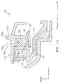
FIGS. 1A-1B illustrate a system that may be used to provide a seal runner with controlled sealing interface oil lubrication in accordance with aspects of the disclosure. -
FIG. 2 illustrates an exemplary gas turbine engine in accordance with aspects of this disclosure. -
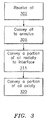
FIG. 3 illustrates a method for providing oil to an interface between a runner and a ring in accordance with aspects of this disclosure. - It is noted that various connections are set forth between elements in the following description and in the drawings (the contents of which are included in this disclosure by way of reference). It is noted that these connections are general and, unless specified otherwise, may be direct or indirect and that this specification is not intended to be limiting in this respect. A coupling between two or more entities may refer to a direct connection or an indirect connection. An indirect connection may incorporate one or more intervening entities.
- In accordance with various aspects of the disclosure, apparatuses, systems and methods are described for providing a seal or seal runner with a controlled sealing interface. In some embodiments, a radial seal or associated seal runner may be provided or utilized. The sealing interface may facilitate sealing with respect to one or more fluids, such as for example oil that is used in lubricating a bearing.
- Aspects of the disclosure are directed to a seal runner with a controlled sealing interface. In some embodiments, oil may be used to lubricate the interface. The interface may be formed by one or more seals, such as for example a segmented circumferential (radial) seal. The runner may contain a set number of upstream feed holes that then may directly (or even indirectly) feed into an annulus (e.g., a three-hundred sixty degree annulus) in an underneath, inner diameter (ID) section of the runner outer portion. This annulus may serve as a reservoir for the oil, such that a dam of oil may develop. The oil may enter a set number of slots that may be spaced (e.g., evenly spaced) around the circumference. These slots may be comprised of at least two different types. Each slot type may be at a set number and spacing so that a predetermined, optimum amount of oil enters each slot type.
- The slot type that would be used for carbon element interface "oil wetting" may be a relatively low quantity (e.g., 1-3 slots), in order to properly control the amount of oil in the interface and the seal oil loss (i.e., weepage) characteristics. This carbon element interface "oil wetting" may be targeted to the runner outer diameter (OD) to carbon element ID sealing interface, which may enable the seal materials to operate at higher rubbing velocities and maintain acceptable wear rates. The optimum location for this interface "oil wetting" targeting may be set to the bearing compartment side (i.e., oil side) ring of the seal arrangement in order to help control the seal oil loss/weepage characteristics. Any air side sealing ring might not be exposed to this direct targeting based on the calculated/expected amount of axial excursions/displacements.
- Referring now to
FIGS. 1A-1B , asystem 100 is shown. Thesystem 100 may be configured to provide a seal runner with controlling sealing interface oil lubrication. - The
system 100 may include aseal runner 104. Therunner 104 may include one or more pieces and may include welded/bonded features to permit machining and drilling. Use of more than one piece may facilitate ease in manufacturing and assembly of thesystem 100. - In association with the
runner 104 there may be a compartmentside oil passage 110. Thepassage 110 may be used in the conveyance of oil, such as for example oil received from one or more sources (e.g., an oil jet - not shown inFIG. 1 ). - The
passage 110 and/or therunner 104 may be associated with one or more radially-oriented holes (as denoted by reference character 116). The holes 116 may be configured to feed oil to an annulus/dam 122 and associatedslots 123. Theannulus 122 may function as a reservoir in terms of a collection or pooling of the oil. The collection/pooling of the oil may be based on a centrifugal force imposed on the oil. - The
runner 104 and/or theannulus 122 may be associated with one or more holes (e.g., one or more lubricating holes) 128 that may provide for optimum interface "wetting" and weepage control. Via theholes 128, a predetermined amount of oil may be delivered across a portion of therunner 104 for purposes of cleaning, cooling, and/or lubricating. Theslots 123 may include, or be associated with, a taper (as denoted via reference character 162) to encourage an axial flow. - The
system 100 may include one or more rings, such as for example an archbound or limited contactair side ring 140 and anoil side ring 146. Therings runner 104, may provide for a sealing arrangement. The use of two rings, e.g. rings 140 and 146, may be used to provide for (a degree of) redundancy in the sealing arrangement. Thering 146 may boarder a bearing compartment annulus, whereas thering 140 may boarder a non-bearing compartment annulus; e.g., an air plenum. However, the present disclosure is not limited to such a configuration. - The
runner 104 may rotate relative to therings runner 104 may rotate in association with the rotation of an engine shaft, whereas therings rings runner 104. Therings - One or both of the
rings rings - Superimposed in
FIG. 1A arereference lines Reference line 152a represents the edge of a chamfer of therunner 104. For purposes of stability/integrity, it might be undesirable for thering 146 to abut against thisvery edge 152a. As such, thereference line 152b may represent a clearance (e.g., a minimum distance) from theedge 152a to position the aft or right-most edge of thering 146. Thereference line 154a may represent the forward or left-most edge of thering 146. Thereference line 154b may represent a clearance (e.g., a minimum distance) from theedge 154a for positioning the forward or left-most edge of the hole(s) 128. The hole(s) 128 may be located so that the hole(s) 128 are contained within the footprint (e.g., an axial projection) of thering 146 based on a gapping analysis/study (e.g., based on excursions/displacements of one or more components of the engine over the operating range of the engine). More particularly, theholes 128 may be positioned axially between the axial sides of thering 146; e.g., betweenreference lines - In some embodiments, the
system 100 may include a scupper system (a portion of which is denoted byreference character 158 inFIG. 1A ). Thescupper system 158 may be used to drain to a benign location any excess oil that may leak out of the seal. - Based on the arrangement of the
system 100, thesystem 100 may be configured to control/meter the amount of oil that is delivered to the interface between thering 146 and therunner 104. For example, a first portion of the oil in theannulus 122 may pass-thru thesystem 100 in, e.g., the axial direction (potentially as part of a manifold) and a second portion of the oil in theannulus 122 may be projected in the radial direction to the interface between thering 146 and therunner 104 via the hole(s) 128. The amount of oil may be controlled/metered by tailoring, for example, the number ofradial holes 128 and/or the diameter of theradial holes 128 to provide a desired flow therethrough. - Aspects of the disclosure may be applied in connection with an aircraft, or portion thereof. For example, aspects of the disclosure may be applied in connection with a gas turbine engine.
FIG. 2 is a side-sectional illustration of an exemplarygas turbine engine 210. Theengine 210 includes acompressor section 212, aturbine section 214 and one or more engine hot sections. The engine hot sections may include, for example, a first enginehot section 216 configured as a combustor section and a second enginehot section 218 configured as an augmentor section. Thecompressor section 212, the first enginehot section 216, theturbine section 214 and the second enginehot section 218 may be sequentially aligned along anaxial centerline 220 between a forwardengine airflow inlet 222 and an aftengine airflow exhaust 224. The second enginehot section 218 may include a first (e.g., annular, radial inner)duct case 226, a second (e.g., annular, radial outer)duct case 228, and one or more hot section vanes 230. - The
engine 210 is illustrative. Aspects of the disclosure may be applied in connection with other engine types or configurations. - Referring to
FIG. 3 , a flow chart of a method 300 is shown. The method 300 may be executed by, or in conjunction with, one or more of the components, devices, or systems described herein. The method 300 may be used to supply oil to one or more interfaces between one or more rings (e.g., ring 146) and a runner (e.g., runner 104). - In
block 302, oil may be received by a runner. The oil may be received from one or more sources, such as for example an oil jet. - In
block 308, the received oil ofblock 302 may be conveyed to an annulus (where the annulus may be included as part of, or associated with, the runner). The conveyance of the oil inblock 308 may be facilitated by one or more holes, e.g., the hole 116. - In
block 314, at least a portion of the oil in the annulus fromblock 308 may be conveyed to an interface between the runner and a ring in a radial direction. The conveyance of the oil inblock 314 may be facilitated by one or more holes, e.g., thehole 128. - In
block 320, at least a portion of the oil in the annulus fromblock 308 may be conveyed in an axial direction, potentially in conjunction with a manifold. - Technical effects and benefits of this disclosure an extension of seal lifetime. Aspects of the disclosure may provide for seal reliability metric improvements, enhanced user/customer satisfaction, and a reduction/minimization in terms of aircraft/engine overhaul cycle requirements. Improved/enhanced durability and wear life may be realized, particularly in the context of high speed applications. Furthermore, such features may be obtained without sacrificing engine performance or fuel efficiency. Aspects of the disclosure may be implemented with a marginal increase in terms of oil that is utilized relative to conventional sealing arrangements.
- Aspects of the disclosure have been described in terms of illustrative embodiments thereof. Numerous other embodiments, modifications, and variations within the scope of the appended claims will occur to persons of ordinary skill in the art from a review of this disclosure. For example, one of ordinary skill in the art will appreciate that the steps described in conjunction with the illustrative figures may be performed in other than the recited order, and that one or more steps illustrated may be optional in accordance with aspects of the disclosure. One or more features described in connection with a first embodiment may be combined with one or more features of one or more additional embodiments.
Claims (15)
- A system associated with an engine (210) of an aircraft, comprising:a ring (146);a runner (104); andat least one radially-oriented hole (116) associated with the runner (104) that is configured to supply oil to an interface between the runner (104) and the ring (146),wherein the at least one hole (116) is contained within an axial projection of the ring (146).
- The system of claim 1, further comprising:an annulus (122) configured to collect oil,wherein a first portion of the collected oil is configured to be conveyed to the interface between the runner (104) and the ring (146) via the at least one hole (116).
- The system of claim 2, wherein the annulus (122) is arranged as a three-hundred sixty degree annulus (122).
- The system of claim 2 or 3, wherein a second portion of the collected oil is configured to pass-thru the system in an axial direction.
- The system of claim 2, 3 or 4 further comprising:at least a second radially-oriented hole configured to provide the oil to the annulus (122).
- The system of any preceding claim, further comprising:a second ring (140) located forward of the ring (146).
- The system of claim 6, wherein at least one of the ring (146) or the second ring (140) is segmented.
- The system of claim 6 or 7, wherein at least one of the ring (146) or the second ring (140) is comprised of carbon.
- The system of any preceding claim, wherein the runner (104) is configured to rotate relative to the ring (146).
- The system of claim 9, wherein the ring (146) is coupled to a shaft of the engine (210), and wherein the ring (146) is coupled to fixed structure of the engine (210).
- The system of claim 1, wherein the runner (104) is configured to interface to the ring (116) as part of a sealing arrangement associated with the engine (210), the runner (104) comprising:an annulus (122) configured to collect oil, wherein the at least one radially-oriented hole (116) is configured to supply oil from the annulus (122) to the interface between the ring (146) and the runner (104).
- The system of claim 11, wherein the runner (104) is configured to interface to a second ring (140) as part of the sealing arrangement; wherein:the runner (104) is configured to avoid supplying oil from the annulus (122) to a second interface between the second ring (140) and the runner (104); and/orthe second ring (140) is located forward of the ring (146).
- A method for providing oil to an interface between a runner (104) and a ring (146) in an engine (210) of an aircraft, the method comprising:receiving, by the runner (104), oil from a source of oil;conveying the received oil to an annulus (122); andconveying at least a first portion of the oil in the annulus (122) to the interface via at least one radially-oriented hole (116) that is contained within an axial projection of the ring (146).
- The method of claim 13, wherein the received oil is conveyed to the annulus (122) via a second at least one radially-oriented hole (116).
- The method of claim 13 or 14, further comprising:conveying a second portion of the oil in the annulus (122) in an axial direction via a manifold.
Applications Claiming Priority (1)
| Application Number | Priority Date | Filing Date | Title |
|---|---|---|---|
| US14/800,400 US9915175B2 (en) | 2015-07-15 | 2015-07-15 | Seal runner with controlled oil lubrication |
Publications (2)
| Publication Number | Publication Date |
|---|---|
| EP3118418A1 true EP3118418A1 (en) | 2017-01-18 |
| EP3118418B1 EP3118418B1 (en) | 2019-11-13 |
Family
ID=56802216
Family Applications (1)
| Application Number | Title | Priority Date | Filing Date |
|---|---|---|---|
| EP16179676.8A Active EP3118418B1 (en) | 2015-07-15 | 2016-07-15 | Seal runner with controlled oil lubrication |
Country Status (2)
| Country | Link |
|---|---|
| US (1) | US9915175B2 (en) |
| EP (1) | EP3118418B1 (en) |
Cited By (2)
| Publication number | Priority date | Publication date | Assignee | Title |
|---|---|---|---|---|
| EP3348883A1 (en) * | 2016-09-22 | 2018-07-18 | MTU Aero Engines GmbH | Sealing arrangement for an intermediate turbine housing of a gas turbine |
| EP3809022B1 (en) * | 2019-10-18 | 2024-09-25 | RTX Corporation | Balanced circumferential seal |
Families Citing this family (12)
| Publication number | Priority date | Publication date | Assignee | Title |
|---|---|---|---|---|
| US10100672B2 (en) * | 2013-03-08 | 2018-10-16 | United Technologies Corporation | Fluid-cooled seal arrangement for a gas turbine engine |
| US10753219B2 (en) * | 2015-05-26 | 2020-08-25 | Pratt & Whitney Canada Corp. | Internally cooled seal runner and method of cooling seal runner of a gas turbine engine |
| FR3075861B1 (en) * | 2017-12-22 | 2019-11-15 | Safran Aircraft Engines | DYNAMIC SEAL BETWEEN TWO ROTORS OF AN AIRCRAFT TURBOMACHINE |
| US10858955B2 (en) | 2018-03-23 | 2020-12-08 | Raytheon Technologies Corporation | Gas turbine engine having a sealing member |
| US10830078B2 (en) * | 2018-09-14 | 2020-11-10 | Raytheon Technologies Corporation | Shaft seal assembly for a turbine engine |
| US11125094B2 (en) * | 2019-04-02 | 2021-09-21 | Raytheon Technologies Corporation | Extended pilot ring seal arrangement for installation damage prevention |
| US11286990B2 (en) * | 2019-04-03 | 2022-03-29 | Raytheon Technologies Corporation | Seal runner with deflector and catcher for gas turbine engine |
| US11299997B2 (en) * | 2019-08-21 | 2022-04-12 | Raytheon Technologies Corporation | Radial seal arrangement with axially elongated oil cooled runner |
| US11840929B2 (en) * | 2020-05-13 | 2023-12-12 | Rtx Corporation | Radial seal arrangement |
| US11371374B2 (en) * | 2020-07-22 | 2022-06-28 | Raytheon Technologies Corporation | Seal runner flow damper |
| DE102020127710A1 (en) * | 2020-10-21 | 2022-04-21 | Rolls-Royce Deutschland Ltd & Co Kg | Device with at least two components and gas turbine engine with such a device |
| US12000299B1 (en) | 2023-08-25 | 2024-06-04 | Rolls-Royce Corporation | Centrifugally operated oil shield for lubrication flow control |
Citations (10)
| Publication number | Priority date | Publication date | Assignee | Title |
|---|---|---|---|---|
| GB2005774A (en) * | 1977-10-07 | 1979-04-25 | Gen Motors Corp | Rotor thrust compensator assembly |
| EP1640627A1 (en) * | 2004-09-23 | 2006-03-29 | General Electric Company | Lubricant distribution weir for lubricating rotating machine elements |
| EP1783329A2 (en) * | 2005-11-03 | 2007-05-09 | United Technologies Corporation | Shrouded face seal |
| EP2302266A1 (en) * | 2009-09-24 | 2011-03-30 | Rolls-Royce plc | Oil seal assembly |
| EP2543827A2 (en) * | 2011-07-06 | 2013-01-09 | Rolls-Royce plc | A sealing arrangement |
| EP2574805A2 (en) * | 2011-09-27 | 2013-04-03 | United Technologies Corporation | Bearing oiling system |
| US20140241851A1 (en) * | 2013-02-27 | 2014-08-28 | United Technologies Corporation | Axial oil scoop for a gas turbine engine |
| US20140369832A1 (en) * | 2013-06-13 | 2014-12-18 | Pratt & Whitney Canada Corp. | Internally cooled seal runner |
| WO2015069348A1 (en) * | 2013-11-06 | 2015-05-14 | United Technologies Corporation | Axial scoop seal plate |
| WO2015094463A1 (en) * | 2013-12-20 | 2015-06-25 | United Technologies Corporation | Seal runner |
Family Cites Families (17)
| Publication number | Priority date | Publication date | Assignee | Title |
|---|---|---|---|---|
| US2158832A (en) | 1937-08-05 | 1939-05-16 | Benjamin B Schneider | Mechanical rubbing-type seal |
| US2956824A (en) | 1957-12-27 | 1960-10-18 | Koppers Co Inc | Vented shaft seal |
| US3252744A (en) | 1961-12-27 | 1966-05-24 | Gen Electric | Dynamoelectric machine |
| GB1028515A (en) | 1961-12-27 | 1966-05-04 | Gen Electric | Improvements in bearing assemblies of contra-rotating electric motors |
| US3704019A (en) | 1970-06-19 | 1972-11-28 | Gen Electric | Spiral groove face seals |
| US3976165A (en) | 1974-05-03 | 1976-08-24 | Norwalk-Turbo, Inc. | Lubricating and oil seal system for a high speed compressor |
| JP3555683B2 (en) * | 1992-08-11 | 2004-08-18 | ユナイテッド・テクノロジーズ・コーポレイション | Seal assembly for rotating machine |
| US5272868A (en) | 1993-04-05 | 1993-12-28 | General Electric Company | Gas turbine engine lubrication system |
| US5547287A (en) | 1993-12-07 | 1996-08-20 | Kmc, Inc. | Method and bearing construction for control of hot oil carryover and loss of lubricant |
| US7648143B2 (en) * | 2005-10-18 | 2010-01-19 | United Technologies Corporation | Tandem dual element intershaft carbon seal |
| US20080284105A1 (en) | 2006-06-21 | 2008-11-20 | Thurai Manik Vasagar | Low and reverse pressure application hydrodynamic pressurizing seals |
| US8490982B2 (en) | 2008-05-22 | 2013-07-23 | Stein Seal Company | Windback device |
| US8246313B2 (en) | 2009-06-29 | 2012-08-21 | Westinghouse Electric Company Llc | Dynamic port for measuring reactor coolant pump bearing oil level |
| US8517612B2 (en) * | 2011-06-30 | 2013-08-27 | United Technologies Corporation | Bearing oiling system |
| US10598222B2 (en) | 2012-01-03 | 2020-03-24 | New Way Machine Components, Inc. | Air bearing for use as seal |
| US9897211B2 (en) * | 2012-12-31 | 2018-02-20 | Thermo King Corporation | Device and method for extending the lifespan of a shaft seal for an open-drive compressor |
| EP2986832B1 (en) | 2013-04-15 | 2017-11-29 | Stein Seal Company | Circumferential back-to-back seal assembly with bifurcated flow |
-
2015
- 2015-07-15 US US14/800,400 patent/US9915175B2/en active Active
-
2016
- 2016-07-15 EP EP16179676.8A patent/EP3118418B1/en active Active
Patent Citations (10)
| Publication number | Priority date | Publication date | Assignee | Title |
|---|---|---|---|---|
| GB2005774A (en) * | 1977-10-07 | 1979-04-25 | Gen Motors Corp | Rotor thrust compensator assembly |
| EP1640627A1 (en) * | 2004-09-23 | 2006-03-29 | General Electric Company | Lubricant distribution weir for lubricating rotating machine elements |
| EP1783329A2 (en) * | 2005-11-03 | 2007-05-09 | United Technologies Corporation | Shrouded face seal |
| EP2302266A1 (en) * | 2009-09-24 | 2011-03-30 | Rolls-Royce plc | Oil seal assembly |
| EP2543827A2 (en) * | 2011-07-06 | 2013-01-09 | Rolls-Royce plc | A sealing arrangement |
| EP2574805A2 (en) * | 2011-09-27 | 2013-04-03 | United Technologies Corporation | Bearing oiling system |
| US20140241851A1 (en) * | 2013-02-27 | 2014-08-28 | United Technologies Corporation | Axial oil scoop for a gas turbine engine |
| US20140369832A1 (en) * | 2013-06-13 | 2014-12-18 | Pratt & Whitney Canada Corp. | Internally cooled seal runner |
| WO2015069348A1 (en) * | 2013-11-06 | 2015-05-14 | United Technologies Corporation | Axial scoop seal plate |
| WO2015094463A1 (en) * | 2013-12-20 | 2015-06-25 | United Technologies Corporation | Seal runner |
Cited By (3)
| Publication number | Priority date | Publication date | Assignee | Title |
|---|---|---|---|---|
| EP3348883A1 (en) * | 2016-09-22 | 2018-07-18 | MTU Aero Engines GmbH | Sealing arrangement for an intermediate turbine housing of a gas turbine |
| US10577959B2 (en) | 2016-09-22 | 2020-03-03 | MTU Aero Engines AG | Seal arrangement for a mid turbine frame of a gas turbine |
| EP3809022B1 (en) * | 2019-10-18 | 2024-09-25 | RTX Corporation | Balanced circumferential seal |
Also Published As
| Publication number | Publication date |
|---|---|
| EP3118418B1 (en) | 2019-11-13 |
| US9915175B2 (en) | 2018-03-13 |
| US20170016350A1 (en) | 2017-01-19 |
Similar Documents
| Publication | Publication Date | Title |
|---|---|---|
| EP3118418B1 (en) | Seal runner with controlled oil lubrication | |
| US10753219B2 (en) | Internally cooled seal runner and method of cooling seal runner of a gas turbine engine | |
| US10030531B2 (en) | Seal shoe for a hydrostatic non-contact seal device | |
| EP2964901B1 (en) | Seal assembly including a notched seal element for arranging between a stator and a rotor | |
| US10088049B2 (en) | Thermally protected seal assembly | |
| US8066473B1 (en) | Floating air seal for a turbine | |
| US9574459B2 (en) | Non-contacting seals for geared gas turbine engine bearing compartments | |
| US20050210875A1 (en) | Turbocharger with hydrodynamic foil bearings | |
| EP3287674B1 (en) | Floating, non-contact seal with offset building clearance for load imbalance | |
| US10337621B2 (en) | Hydrostatic non-contact seal with weight reduction pocket | |
| EP3290755A1 (en) | Floating, non-contact seal with at least three beams | |
| US20150345319A1 (en) | Dual walled seal assembly | |
| US11199103B2 (en) | Seal assembly for a turbomachine | |
| CN110056430B (en) | Bearing common-cavity lubricating and shaft-to-shaft sealing device and birotor aero-engine | |
| US20190226585A1 (en) | Hydrodynamic Intershaft Piston Ring Seal | |
| US11371441B2 (en) | Translating fluid delivery device | |
| US10598035B2 (en) | Intershaft sealing systems for gas turbine engines and methods for assembling the same | |
| US7435052B2 (en) | Shaft oil purge system | |
| EP3048344A2 (en) | Seal housing pre-taper | |
| US20200063587A1 (en) | Axially preloaded seal | |
| US10557362B2 (en) | Method and system for a pressure activated cap seal | |
| US10670077B2 (en) | Sealed bearing assembly and method of forming same | |
| EP2613006A1 (en) | Turbine assembly and method for reducing fluid flow between turbine components | |
| EP3712395B1 (en) | Seal assembly for a gas turbine engine | |
| US10612409B2 (en) | Active clearance control collector to manifold insert |
Legal Events
| Date | Code | Title | Description |
|---|---|---|---|
| PUAI | Public reference made under article 153(3) epc to a published international application that has entered the european phase |
Free format text: ORIGINAL CODE: 0009012 |
|
| STAA | Information on the status of an ep patent application or granted ep patent |
Free format text: STATUS: THE APPLICATION HAS BEEN PUBLISHED |
|
| AK | Designated contracting states |
Kind code of ref document: A1 Designated state(s): AL AT BE BG CH CY CZ DE DK EE ES FI FR GB GR HR HU IE IS IT LI LT LU LV MC MK MT NL NO PL PT RO RS SE SI SK SM TR |
|
| AX | Request for extension of the european patent |
Extension state: BA ME |
|
| STAA | Information on the status of an ep patent application or granted ep patent |
Free format text: STATUS: REQUEST FOR EXAMINATION WAS MADE |
|
| 17P | Request for examination filed |
Effective date: 20170717 |
|
| RBV | Designated contracting states (corrected) |
Designated state(s): AL AT BE BG CH CY CZ DE DK EE ES FI FR GB GR HR HU IE IS IT LI LT LU LV MC MK MT NL NO PL PT RO RS SE SI SK SM TR |
|
| STAA | Information on the status of an ep patent application or granted ep patent |
Free format text: STATUS: EXAMINATION IS IN PROGRESS |
|
| 17Q | First examination report despatched |
Effective date: 20181022 |
|
| GRAP | Despatch of communication of intention to grant a patent |
Free format text: ORIGINAL CODE: EPIDOSNIGR1 |
|
| STAA | Information on the status of an ep patent application or granted ep patent |
Free format text: STATUS: GRANT OF PATENT IS INTENDED |
|
| INTG | Intention to grant announced |
Effective date: 20190606 |
|
| GRAS | Grant fee paid |
Free format text: ORIGINAL CODE: EPIDOSNIGR3 |
|
| GRAA | (expected) grant |
Free format text: ORIGINAL CODE: 0009210 |
|
| STAA | Information on the status of an ep patent application or granted ep patent |
Free format text: STATUS: THE PATENT HAS BEEN GRANTED |
|
| AK | Designated contracting states |
Kind code of ref document: B1 Designated state(s): AL AT BE BG CH CY CZ DE DK EE ES FI FR GB GR HR HU IE IS IT LI LT LU LV MC MK MT NL NO PL PT RO RS SE SI SK SM TR |
|
| REG | Reference to a national code |
Ref country code: CH Ref legal event code: EP Ref country code: AT Ref legal event code: REF Ref document number: 1201859 Country of ref document: AT Kind code of ref document: T Effective date: 20191115 |
|
| REG | Reference to a national code |
Ref country code: DE Ref legal event code: R096 Ref document number: 602016024163 Country of ref document: DE |
|
| REG | Reference to a national code |
Ref country code: IE Ref legal event code: FG4D |
|
| REG | Reference to a national code |
Ref country code: NL Ref legal event code: MP Effective date: 20191113 |
|
| REG | Reference to a national code |
Ref country code: LT Ref legal event code: MG4D |
|
| PG25 | Lapsed in a contracting state [announced via postgrant information from national office to epo] |
Ref country code: NO Free format text: LAPSE BECAUSE OF FAILURE TO SUBMIT A TRANSLATION OF THE DESCRIPTION OR TO PAY THE FEE WITHIN THE PRESCRIBED TIME-LIMIT Effective date: 20200213 Ref country code: GR Free format text: LAPSE BECAUSE OF FAILURE TO SUBMIT A TRANSLATION OF THE DESCRIPTION OR TO PAY THE FEE WITHIN THE PRESCRIBED TIME-LIMIT Effective date: 20200214 Ref country code: BG Free format text: LAPSE BECAUSE OF FAILURE TO SUBMIT A TRANSLATION OF THE DESCRIPTION OR TO PAY THE FEE WITHIN THE PRESCRIBED TIME-LIMIT Effective date: 20200213 Ref country code: PL Free format text: LAPSE BECAUSE OF FAILURE TO SUBMIT A TRANSLATION OF THE DESCRIPTION OR TO PAY THE FEE WITHIN THE PRESCRIBED TIME-LIMIT Effective date: 20191113 Ref country code: FI Free format text: LAPSE BECAUSE OF FAILURE TO SUBMIT A TRANSLATION OF THE DESCRIPTION OR TO PAY THE FEE WITHIN THE PRESCRIBED TIME-LIMIT Effective date: 20191113 Ref country code: LT Free format text: LAPSE BECAUSE OF FAILURE TO SUBMIT A TRANSLATION OF THE DESCRIPTION OR TO PAY THE FEE WITHIN THE PRESCRIBED TIME-LIMIT Effective date: 20191113 Ref country code: NL Free format text: LAPSE BECAUSE OF FAILURE TO SUBMIT A TRANSLATION OF THE DESCRIPTION OR TO PAY THE FEE WITHIN THE PRESCRIBED TIME-LIMIT Effective date: 20191113 Ref country code: PT Free format text: LAPSE BECAUSE OF FAILURE TO SUBMIT A TRANSLATION OF THE DESCRIPTION OR TO PAY THE FEE WITHIN THE PRESCRIBED TIME-LIMIT Effective date: 20200313 Ref country code: SE Free format text: LAPSE BECAUSE OF FAILURE TO SUBMIT A TRANSLATION OF THE DESCRIPTION OR TO PAY THE FEE WITHIN THE PRESCRIBED TIME-LIMIT Effective date: 20191113 Ref country code: LV Free format text: LAPSE BECAUSE OF FAILURE TO SUBMIT A TRANSLATION OF THE DESCRIPTION OR TO PAY THE FEE WITHIN THE PRESCRIBED TIME-LIMIT Effective date: 20191113 |
|
| PG25 | Lapsed in a contracting state [announced via postgrant information from national office to epo] |
Ref country code: IS Free format text: LAPSE BECAUSE OF FAILURE TO SUBMIT A TRANSLATION OF THE DESCRIPTION OR TO PAY THE FEE WITHIN THE PRESCRIBED TIME-LIMIT Effective date: 20200313 Ref country code: RS Free format text: LAPSE BECAUSE OF FAILURE TO SUBMIT A TRANSLATION OF THE DESCRIPTION OR TO PAY THE FEE WITHIN THE PRESCRIBED TIME-LIMIT Effective date: 20191113 Ref country code: HR Free format text: LAPSE BECAUSE OF FAILURE TO SUBMIT A TRANSLATION OF THE DESCRIPTION OR TO PAY THE FEE WITHIN THE PRESCRIBED TIME-LIMIT Effective date: 20191113 |
|
| PG25 | Lapsed in a contracting state [announced via postgrant information from national office to epo] |
Ref country code: AL Free format text: LAPSE BECAUSE OF FAILURE TO SUBMIT A TRANSLATION OF THE DESCRIPTION OR TO PAY THE FEE WITHIN THE PRESCRIBED TIME-LIMIT Effective date: 20191113 |
|
| PG25 | Lapsed in a contracting state [announced via postgrant information from national office to epo] |
Ref country code: ES Free format text: LAPSE BECAUSE OF FAILURE TO SUBMIT A TRANSLATION OF THE DESCRIPTION OR TO PAY THE FEE WITHIN THE PRESCRIBED TIME-LIMIT Effective date: 20191113 Ref country code: RO Free format text: LAPSE BECAUSE OF FAILURE TO SUBMIT A TRANSLATION OF THE DESCRIPTION OR TO PAY THE FEE WITHIN THE PRESCRIBED TIME-LIMIT Effective date: 20191113 Ref country code: CZ Free format text: LAPSE BECAUSE OF FAILURE TO SUBMIT A TRANSLATION OF THE DESCRIPTION OR TO PAY THE FEE WITHIN THE PRESCRIBED TIME-LIMIT Effective date: 20191113 Ref country code: DK Free format text: LAPSE BECAUSE OF FAILURE TO SUBMIT A TRANSLATION OF THE DESCRIPTION OR TO PAY THE FEE WITHIN THE PRESCRIBED TIME-LIMIT Effective date: 20191113 Ref country code: EE Free format text: LAPSE BECAUSE OF FAILURE TO SUBMIT A TRANSLATION OF THE DESCRIPTION OR TO PAY THE FEE WITHIN THE PRESCRIBED TIME-LIMIT Effective date: 20191113 |
|
| REG | Reference to a national code |
Ref country code: DE Ref legal event code: R097 Ref document number: 602016024163 Country of ref document: DE |
|
| REG | Reference to a national code |
Ref country code: AT Ref legal event code: MK05 Ref document number: 1201859 Country of ref document: AT Kind code of ref document: T Effective date: 20191113 |
|
| PG25 | Lapsed in a contracting state [announced via postgrant information from national office to epo] |
Ref country code: SK Free format text: LAPSE BECAUSE OF FAILURE TO SUBMIT A TRANSLATION OF THE DESCRIPTION OR TO PAY THE FEE WITHIN THE PRESCRIBED TIME-LIMIT Effective date: 20191113 Ref country code: SM Free format text: LAPSE BECAUSE OF FAILURE TO SUBMIT A TRANSLATION OF THE DESCRIPTION OR TO PAY THE FEE WITHIN THE PRESCRIBED TIME-LIMIT Effective date: 20191113 |
|
| PLBE | No opposition filed within time limit |
Free format text: ORIGINAL CODE: 0009261 |
|
| STAA | Information on the status of an ep patent application or granted ep patent |
Free format text: STATUS: NO OPPOSITION FILED WITHIN TIME LIMIT |
|
| 26N | No opposition filed |
Effective date: 20200814 |
|
| PG25 | Lapsed in a contracting state [announced via postgrant information from national office to epo] |
Ref country code: AT Free format text: LAPSE BECAUSE OF FAILURE TO SUBMIT A TRANSLATION OF THE DESCRIPTION OR TO PAY THE FEE WITHIN THE PRESCRIBED TIME-LIMIT Effective date: 20191113 Ref country code: SI Free format text: LAPSE BECAUSE OF FAILURE TO SUBMIT A TRANSLATION OF THE DESCRIPTION OR TO PAY THE FEE WITHIN THE PRESCRIBED TIME-LIMIT Effective date: 20191113 |
|
| PG25 | Lapsed in a contracting state [announced via postgrant information from national office to epo] |
Ref country code: IT Free format text: LAPSE BECAUSE OF FAILURE TO SUBMIT A TRANSLATION OF THE DESCRIPTION OR TO PAY THE FEE WITHIN THE PRESCRIBED TIME-LIMIT Effective date: 20191113 |
|
| PG25 | Lapsed in a contracting state [announced via postgrant information from national office to epo] |
Ref country code: MC Free format text: LAPSE BECAUSE OF FAILURE TO SUBMIT A TRANSLATION OF THE DESCRIPTION OR TO PAY THE FEE WITHIN THE PRESCRIBED TIME-LIMIT Effective date: 20191113 |
|
| REG | Reference to a national code |
Ref country code: CH Ref legal event code: PL |
|
| REG | Reference to a national code |
Ref country code: BE Ref legal event code: MM Effective date: 20200731 |
|
| PG25 | Lapsed in a contracting state [announced via postgrant information from national office to epo] |
Ref country code: LU Free format text: LAPSE BECAUSE OF NON-PAYMENT OF DUE FEES Effective date: 20200715 Ref country code: LI Free format text: LAPSE BECAUSE OF NON-PAYMENT OF DUE FEES Effective date: 20200731 Ref country code: CH Free format text: LAPSE BECAUSE OF NON-PAYMENT OF DUE FEES Effective date: 20200731 |
|
| PG25 | Lapsed in a contracting state [announced via postgrant information from national office to epo] |
Ref country code: BE Free format text: LAPSE BECAUSE OF NON-PAYMENT OF DUE FEES Effective date: 20200731 |
|
| PG25 | Lapsed in a contracting state [announced via postgrant information from national office to epo] |
Ref country code: IE Free format text: LAPSE BECAUSE OF NON-PAYMENT OF DUE FEES Effective date: 20200715 |
|
| PG25 | Lapsed in a contracting state [announced via postgrant information from national office to epo] |
Ref country code: TR Free format text: LAPSE BECAUSE OF FAILURE TO SUBMIT A TRANSLATION OF THE DESCRIPTION OR TO PAY THE FEE WITHIN THE PRESCRIBED TIME-LIMIT Effective date: 20191113 Ref country code: MT Free format text: LAPSE BECAUSE OF FAILURE TO SUBMIT A TRANSLATION OF THE DESCRIPTION OR TO PAY THE FEE WITHIN THE PRESCRIBED TIME-LIMIT Effective date: 20191113 Ref country code: CY Free format text: LAPSE BECAUSE OF FAILURE TO SUBMIT A TRANSLATION OF THE DESCRIPTION OR TO PAY THE FEE WITHIN THE PRESCRIBED TIME-LIMIT Effective date: 20191113 |
|
| PG25 | Lapsed in a contracting state [announced via postgrant information from national office to epo] |
Ref country code: MK Free format text: LAPSE BECAUSE OF FAILURE TO SUBMIT A TRANSLATION OF THE DESCRIPTION OR TO PAY THE FEE WITHIN THE PRESCRIBED TIME-LIMIT Effective date: 20191113 |
|
| REG | Reference to a national code |
Ref country code: DE Ref legal event code: R081 Ref document number: 602016024163 Country of ref document: DE Owner name: RAYTHEON TECHNOLOGIES CORPORATION (N.D.GES.D.S, US Free format text: FORMER OWNER: UNITED TECHNOLOGIES CORPORATION, FARMINGTON, CONN., US Ref country code: DE Ref legal event code: R081 Ref document number: 602016024163 Country of ref document: DE Owner name: RTX CORPORATION (N.D.GES.D. STAATES DELAWARE),, US Free format text: FORMER OWNER: UNITED TECHNOLOGIES CORPORATION, FARMINGTON, CONN., US |
|
| P01 | Opt-out of the competence of the unified patent court (upc) registered |
Effective date: 20230520 |
|
| PGFP | Annual fee paid to national office [announced via postgrant information from national office to epo] |
Ref country code: GB Payment date: 20250619 Year of fee payment: 10 |
|
| PGFP | Annual fee paid to national office [announced via postgrant information from national office to epo] |
Ref country code: FR Payment date: 20250620 Year of fee payment: 10 |
|
| PGFP | Annual fee paid to national office [announced via postgrant information from national office to epo] |
Ref country code: DE Payment date: 20250620 Year of fee payment: 10 |
|
| REG | Reference to a national code |
Ref country code: DE Ref legal event code: R081 Ref document number: 602016024163 Country of ref document: DE Owner name: RTX CORPORATION (N.D.GES.D. STAATES DELAWARE),, US Free format text: FORMER OWNER: RAYTHEON TECHNOLOGIES CORPORATION (N.D.GES.D.STAATES DELAWARE), ARLINGTON, VA, US |