EP3118107A1 - Wheel and tire sealing system with fuse plug - Google Patents
Wheel and tire sealing system with fuse plug Download PDFInfo
- Publication number
- EP3118107A1 EP3118107A1 EP16179902.8A EP16179902A EP3118107A1 EP 3118107 A1 EP3118107 A1 EP 3118107A1 EP 16179902 A EP16179902 A EP 16179902A EP 3118107 A1 EP3118107 A1 EP 3118107A1
- Authority
- EP
- European Patent Office
- Prior art keywords
- wall
- wheel
- fuse plug
- seal ring
- passage
- Prior art date
- Legal status (The legal status is an assumption and is not a legal conclusion. Google has not performed a legal analysis and makes no representation as to the accuracy of the status listed.)
- Granted
Links
Images



Classifications
-
- B—PERFORMING OPERATIONS; TRANSPORTING
- B60—VEHICLES IN GENERAL
- B60B—VEHICLE WHEELS; CASTORS; AXLES FOR WHEELS OR CASTORS; INCREASING WHEEL ADHESION
- B60B21/00—Rims
- B60B21/12—Appurtenances, e.g. lining bands
-
- B—PERFORMING OPERATIONS; TRANSPORTING
- B64—AIRCRAFT; AVIATION; COSMONAUTICS
- B64C—AEROPLANES; HELICOPTERS
- B64C25/00—Alighting gear
- B64C25/32—Alighting gear characterised by elements which contact the ground or similar surface
- B64C25/34—Alighting gear characterised by elements which contact the ground or similar surface wheeled type, e.g. multi-wheeled bogies
- B64C25/36—Arrangements or adaptations of wheels, tyres or axles in general
-
- B—PERFORMING OPERATIONS; TRANSPORTING
- B60—VEHICLES IN GENERAL
- B60B—VEHICLE WHEELS; CASTORS; AXLES FOR WHEELS OR CASTORS; INCREASING WHEEL ADHESION
- B60B21/00—Rims
- B60B21/02—Rims characterised by transverse section
-
- F—MECHANICAL ENGINEERING; LIGHTING; HEATING; WEAPONS; BLASTING
- F16—ENGINEERING ELEMENTS AND UNITS; GENERAL MEASURES FOR PRODUCING AND MAINTAINING EFFECTIVE FUNCTIONING OF MACHINES OR INSTALLATIONS; THERMAL INSULATION IN GENERAL
- F16K—VALVES; TAPS; COCKS; ACTUATING-FLOATS; DEVICES FOR VENTING OR AERATING
- F16K17/00—Safety valves; Equalising valves, e.g. pressure relief valves
- F16K17/36—Safety valves; Equalising valves, e.g. pressure relief valves actuated in consequence of extraneous circumstances, e.g. shock, change of position
- F16K17/38—Safety valves; Equalising valves, e.g. pressure relief valves actuated in consequence of extraneous circumstances, e.g. shock, change of position of excessive temperature
- F16K17/383—Safety valves; Equalising valves, e.g. pressure relief valves actuated in consequence of extraneous circumstances, e.g. shock, change of position of excessive temperature the valve comprising fusible, softening or meltable elements, e.g. used as link, blocking element, seal, closure plug
-
- F—MECHANICAL ENGINEERING; LIGHTING; HEATING; WEAPONS; BLASTING
- F16—ENGINEERING ELEMENTS AND UNITS; GENERAL MEASURES FOR PRODUCING AND MAINTAINING EFFECTIVE FUNCTIONING OF MACHINES OR INSTALLATIONS; THERMAL INSULATION IN GENERAL
- F16K—VALVES; TAPS; COCKS; ACTUATING-FLOATS; DEVICES FOR VENTING OR AERATING
- F16K17/00—Safety valves; Equalising valves, e.g. pressure relief valves
- F16K17/40—Safety valves; Equalising valves, e.g. pressure relief valves with a fracturing member, e.g. fracturing diaphragm, glass, fusible joint
Definitions
- the present disclosure relates to plugs for pressurized systems, and, more specifically, to a fuse plug for use in a pressurized system.
- the braking systems may be subject to extreme heat.
- Hard braking applied on shorter runways may augment the heat increase of the braking system.
- the heat in the brake systems may result in a significant increase in tire temperature and pressure. Extreme increases in temperature and pressure may tend to liberate tires from wheels.
- Plugs and valves in the wheels may be used to vent pressure as wheels and tires are exposed to temperature and pressure increases. However, after heat cycling combined with rolling stresses on the wheels, the plugs and valves may not seal air as well as when they were first installed. During landing and RTO events the increased pressure in the tires may cause air to evacuate the tires at a relatively high rate. Thus, the plugs and valves used in wheel systems may tend to increase tire-pressure maintenance.
- a fuse plug may comprise an annular body having a passage defined by an inner wall.
- a groove may be formed circumferentially about an outer surface of the annular body.
- a seal ring may be configured to settle in the groove.
- a fusible material may be retained within the passage defined by the inner wall.
- the seal ring may be configured to sealably engage a wall of an aperture.
- the annular body may comprise aluminum.
- the fusible material may comprise a tin and zinc alloy.
- the seal ring may comprise silicone.
- the annular body may comprise a layer of nickel on the inner wall.
- the groove may comprise a radial contour.
- a plug may comprise an annular body having a passage defined by an inner wall.
- the inner wall may comprise a nickel layer.
- a groove may be formed circumferentially about an outer surface of the annular body, and a seal ring may be configured to settle in the groove.
- the seal ring may also comprise at least one of silicone or rubber.
- a fusible material may be retained within the passage defined by the inner wall.
- the seal ring may be configured to sealably engage a wall of an aperture.
- a diameter of the inner wall may be between 0.149 inches and 0.151 inches (3.78 mm and 3.84 mm).
- An outer diameter of the annular body may be between 0.245 inches and 0.247 inches (6.22 mm and 6.27 mm).
- a diameter of the seal ring may be between 0.175 inches and 0.185 inches (4.45 mm and 4.70 mm).
- the fusible material may be flush within 0.015 inches (0.381 mm) of an end surface of the annular body.
- the annular body may comprise aluminum.
- the fusible material may comprise a tin and zinc alloy.
- a wheel and tire system may include a wheel, a tire disposed about the wheel and defining a chamber between the wheel and the tire, and a first passage to the chamber through the wheel.
- a fuse plug may be disposed within the first passage.
- the fuse plug may comprise an annular body having a second passage defined by an inner wall.
- a groove may be formed circumferentially about an outer surface of the annular body.
- a seal ring may be configured to settle in the groove and sealably engage the first passage.
- a fusible material may be retained within the second passage defined by the inner wall.
- the annular body may comprise aluminum.
- the fusible material may comprise a tin and zinc alloy.
- the annular body may also comprise a layer of nickel on the inner wall.
- the seal ring may comprise at least one of silicone or rubber.
- any reference to singular includes plural embodiments, and any reference to more than one component or step may include a singular embodiment or step.
- any reference to attached, fixed, connected or the like may include permanent, removable, temporary, partial, full and/or any other possible attachment option.
- any reference to without contact (or similar phrases) may also include reduced contact or minimal contact. Surface shading lines may be used throughout the figures to denote different parts but not necessarily to denote the same or different materials.
- Fuse plugs may be used to seal an opening in a wheel to allow venting of tire pressure during RTO and/or landing events.
- the fuse plugs may comprise a fusible material inside of an annular, rigid body.
- the fusible material e.g., a eutectic alloy
- the fusible material may melt in response to the elevated temperature and pressure within the tire.
- the fusible material may then liberate from the rigid body, allowing air to vent from the tire.
- the rigid body may be retained in the wheel or ejected.
- Fusible plugs of the present disclosure may be retained within adapters or directly in wheels.
- the fusible plugs may also enable increased venting air flow and improve air retention absent the elevated temperatures of RTO and landing events.
- Wheel 104 may comprise a hub 102 located centrally and a wall 106 configured to interface with tire 108.
- a chamber may thus be formed between wall 106 of wheel 104 and tire 108.
- Passage 112 (also referred to herein as an aperture, cavity, or opening) may be formed through wall 106 of wheel 104. Passage 112 may fluidly connect the chamber between tire 108 and wall 106 to the surrounding atmosphere.
- Fuse plug 110 may be lodged in passage 112 to seal the chamber between tire 108 and wall 106. Fuse plug 110 may partially or completely eject from passage 112 in response to elevated temperatures combined with air pressure directed radially inward towards hub 102.
- Fuse plug 110 may have an annulus 120, also referred to herein as an annular body.
- Annulus 120 may be formed from a metallic material such as an aluminum alloy.
- annulus 120 may be formed from specification 6061 aluminum alloy.
- 6061 aluminum alloy may have a composition of silicon (minimum 0.4%, maximum 0.8% by weight), iron (no minimum, maximum 0.70% by weight), copper (minimum 0.15%, maximum 0.40% by weight), manganese (no minimum, maximum 0.15% by weight), magnesium (minimum 0.8%, maximum 1.2% by weight), chromium (minimum 0.04%, maximum 0.35% by weight), zinc (no minimum, maximum 0.25% by weight), titanium (no minimum, maximum 0.15% by weight), other elements (no more than 0.05% each, 0.15% total by weight), with a remainder of aluminum (95.85% to 98.56% by weight).
- the metallic material may be selected for favorable corrosion properties as annulus 120 comes into contact with fusible material 122 or with a nickel coating formed on inner surface 130.
- annulus 120 may retain a fusible material 122, also referred to herein as a eutectic alloy, in a central cavity defined by inner surface 130 of annulus 120.
- Fusible material 122 may comprise a tin alloy selected for favorable corrosion characteristics with annulus 120.
- fusible material may be a eutectic alloy comprising 91% tin by weight and 9% zinc by weight, other tin and zinc alloys, or other eutectic alloys having a suitable melting point (i.e., a melting point below the elevated temperature during an RTO and/or or landing event 199°C (390°F).
- Outer surface 131 of fusible material may contact and bond to inner surface 130 of annulus 120.
- Annulus 120 may have groove 124 formed about an outer diameter of annulus 120 circumferentially and configured to retain seal ring 126 in groove 124.
- Groove 124 may be a radial groove having a radial contour of radius R1.
- Radius R1 may be 0.016 inches (0.41 mm). Radius R1 may also be between 0.01 inches (0.25 mm) and 0.02 inches (0.51 mm).
- Seal ring 126 may rest in groove 124 to provide sealing between annulus 120 and passage 112 of FIG. 1 .
- Seal ring 126 may comprise a silicone or rubber material having flexible properties allowing seal ring 126 to expand and pass around annulus 120 and contract to settle in groove 124.
- Groove 124 may retain seal ring 126 in place about annulus 120.
- fuse plug 110 may be axially symmetric about axis A-A'.
- Annulus 120 may have an outer diameter D1 and an inner diameter D2. Outer diameter D1 may range from 0.247 inches to 0.245 inches (6.27 mm to 6.22 mm).
- Outer surface 131 of fusible material 122 may be bonded to annulus 120 along inner surface 130.
- Surface 123 of fusible material 122 may be a flat surface protruding slightly from, recessed slightly from, or flush with end surface 121 of annulus 120. Surface 123 of fusible material 122 may thus be flush within 0.015 inches (0.381 mm) of end surface 121.
- Inner surface 130 of annulus 120 may comprise a nickel coating so that a nickel layer is disposed between fusible material 122 and inner surface 130
- Seal ring 126 may be an annular ring having a circular cross section. Seal ring 126 may have a diameter D3 that is less than outer diameter D1 so that seal ring 126 settles in groove 124. Diameter D3 may be between 0.185 and 0.175 inches (4.70 mm and 4.45 mm), for example. Seal ring 126 may have an inner diameter 134 and outer diameter 132 with inner diameter 134 having the diameter D3. Seal ring 126 may be axially symmetric about axis B-B'. Seal ring 126 may have an axial diameter D4. Axial diameter D4 may be between 0.035 and 0.041 inches (0.889 mm and 1.04 mm).
- seal system 148 is shown with fuse plug 110 inserted into passage 154 of structure 150.
- Wall 152 may engage fuse plug 110 and sealably engage seal ring 126.
- Wall 152 of structure 150 may define cylindrical opening having diameter D5.
- Fuse plug 110 may lodge in passage 154 against wall 152 and obstruct passage 154 to prevent gas from flowing through passage 154.
- Fuse plug 110 may be smaller than passage 154 with space available between fuse plug 110 and wall 152 for gas to pass through.
- Seal ring 126 may sealably engage wall 152 in a manner that deforms seal ring 126 and limits or prevents gas from passing through passage 154 between fuse plug 110 and wall 152.
- fuse plug 110 may melt and eject from annulus 120 and out from passage 154.
- Annulus 120 may be retained in passage 154 with an opening for air to pass through where fusible material 122 was previously located.
- fuse plug 110 and passage 154 may enable evacuation of high pressure air in response to a RTO or landing event.
- fuse plug 110 with an annulus 120 may improve durability across heat cycles and rolling wheel stresses and improve the joint between fusible material 122 and annulus 120 to air leakage.
- references to "various embodiments”, “one embodiment”, “an embodiment”, “an example embodiment”, etc. indicate that the embodiment described may include a particular feature, structure, or characteristic, but every embodiment may not necessarily include the particular feature, structure, or characteristic. Moreover, such phrases are not necessarily referring to the same embodiment. Further, when a particular feature, structure, or characteristic is described in connection with an embodiment, it is submitted that it is within the knowledge of one skilled in the art to affect such feature, structure, or characteristic in connection with other embodiments whether or not explicitly described. After reading the description, it will be apparent to one skilled in the relevant art(s) how to implement the disclosure in alternative embodiments.
Landscapes
- Engineering & Computer Science (AREA)
- Mechanical Engineering (AREA)
- General Engineering & Computer Science (AREA)
- Aviation & Aerospace Engineering (AREA)
- Gasket Seals (AREA)
Abstract
Description
- The present disclosure relates to plugs for pressurized systems, and, more specifically, to a fuse plug for use in a pressurized system.
- Aircraft accelerate and decelerate quickly on land, relying heavily on wheel braking systems. During a rejected takeoff (RTO) or a landing, the braking systems may be subject to extreme heat. Hard braking applied on shorter runways may augment the heat increase of the braking system. The heat in the brake systems may result in a significant increase in tire temperature and pressure. Extreme increases in temperature and pressure may tend to liberate tires from wheels.
- Plugs and valves in the wheels may be used to vent pressure as wheels and tires are exposed to temperature and pressure increases. However, after heat cycling combined with rolling stresses on the wheels, the plugs and valves may not seal air as well as when they were first installed. During landing and RTO events the increased pressure in the tires may cause air to evacuate the tires at a relatively high rate. Thus, the plugs and valves used in wheel systems may tend to increase tire-pressure maintenance.
- According to various embodiments, a fuse plug may comprise an annular body having a passage defined by an inner wall. A groove may be formed circumferentially about an outer surface of the annular body. A seal ring may be configured to settle in the groove. A fusible material may be retained within the passage defined by the inner wall.
- In various embodiments, the seal ring may be configured to sealably engage a wall of an aperture. The annular body may comprise aluminum. The fusible material may comprise a tin and zinc alloy. The seal ring may comprise silicone. The annular body may comprise a layer of nickel on the inner wall. The groove may comprise a radial contour.
- According to various embodiments, a plug may comprise an annular body having a passage defined by an inner wall. The inner wall may comprise a nickel layer. A groove may be formed circumferentially about an outer surface of the annular body, and a seal ring may be configured to settle in the groove. The seal ring may also comprise at least one of silicone or rubber. A fusible material may be retained within the passage defined by the inner wall.
- In various embodiments, the seal ring may be configured to sealably engage a wall of an aperture. A diameter of the inner wall may be between 0.149 inches and 0.151 inches (3.78 mm and 3.84 mm). An outer diameter of the annular body may be between 0.245 inches and 0.247 inches (6.22 mm and 6.27 mm). A diameter of the seal ring may be between 0.175 inches and 0.185 inches (4.45 mm and 4.70 mm). The fusible material may be flush within 0.015 inches (0.381 mm) of an end surface of the annular body. The annular body may comprise aluminum. The fusible material may comprise a tin and zinc alloy.
- According to various embodiments, a wheel and tire system may include a wheel, a tire disposed about the wheel and defining a chamber between the wheel and the tire, and a first passage to the chamber through the wheel. A fuse plug may be disposed within the first passage. The fuse plug may comprise an annular body having a second passage defined by an inner wall. A groove may be formed circumferentially about an outer surface of the annular body. A seal ring may be configured to settle in the groove and sealably engage the first passage. A fusible material may be retained within the second passage defined by the inner wall.
- In various embodiments, the annular body may comprise aluminum. The fusible material may comprise a tin and zinc alloy. The annular body may also comprise a layer of nickel on the inner wall. The seal ring may comprise at least one of silicone or rubber.
- The foregoing features and elements may be combined in various combinations without exclusivity, unless expressly indicated otherwise. These features and elements as well as the operation thereof will become more apparent in light of the following description and the accompanying drawings. It should be understood, however, the following description and drawings are intended to be exemplary in nature and non-limiting.
- The subject matter of the present disclosure is particularly pointed out and distinctly claimed in the concluding portion of the specification. A more complete understanding of the present disclosure, however, may best be obtained by referring to the detailed description and claims when considered in connection with the figures, wherein like numerals denote like elements.
-
FIG. 1 illustrates an exemplary wheel and tire system including a fuse plug to seal a pressurized compartment, in accordance with various embodiments; -
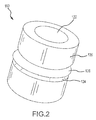
FIG. 2 illustrates a fuse plug having a fusible portion within a rigid body and a ring seal, in accordance with various embodiments; -
FIG. 3 illustrates a cross-sectional view of a fuse plug having a fusible material retained within a body; -
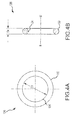
FIG. 4A illustrates a seal ring for use with a fuse plug, in accordance with various embodiments; -
FIG. 4B illustrates a cross-sectional view of a seal ring for use with a fuse plug, in accordance with various embodiments; and -
FIG. 5 illustrates a perspective view of a threaded adapter having an opening to receive a fuse plug, in accordance with various embodiments. - The detailed description of exemplary embodiments herein makes reference to the accompanying drawings, which show exemplary embodiments by way of illustration. While these exemplary embodiments are described in sufficient detail to enable those skilled in the art to practice the exemplary embodiments of the disclosure, it should be understood that other embodiments may be realized and that logical changes and adaptations in design and construction may be made in accordance with this disclosure and the teachings herein. Thus, the detailed description herein is presented for purposes of illustration only and not limitation. The steps recited in any of the method or process descriptions may be executed in any order and are not necessarily limited to the order presented.
- Furthermore, any reference to singular includes plural embodiments, and any reference to more than one component or step may include a singular embodiment or step. Also, any reference to attached, fixed, connected or the like may include permanent, removable, temporary, partial, full and/or any other possible attachment option. Additionally, any reference to without contact (or similar phrases) may also include reduced contact or minimal contact. Surface shading lines may be used throughout the figures to denote different parts but not necessarily to denote the same or different materials.
- Fuse plugs may be used to seal an opening in a wheel to allow venting of tire pressure during RTO and/or landing events. The fuse plugs may comprise a fusible material inside of an annular, rigid body. The fusible material (e.g., a eutectic alloy) may melt in response to the elevated temperature and pressure within the tire. The fusible material may then liberate from the rigid body, allowing air to vent from the tire. The rigid body may be retained in the wheel or ejected. Fusible plugs of the present disclosure may be retained within adapters or directly in wheels. The fusible plugs may also enable increased venting air flow and improve air retention absent the elevated temperatures of RTO and landing events.
- With reference to
FIG. 1 , an exemplary wheel andtire system 100 is shown, in accordance with various embodiments.Wheel 104 may comprise ahub 102 located centrally and awall 106 configured to interface withtire 108. A chamber may thus be formed betweenwall 106 ofwheel 104 andtire 108. Passage 112 (also referred to herein as an aperture, cavity, or opening) may be formed throughwall 106 ofwheel 104.Passage 112 may fluidly connect the chamber betweentire 108 andwall 106 to the surrounding atmosphere.Fuse plug 110 may be lodged inpassage 112 to seal the chamber betweentire 108 andwall 106.Fuse plug 110 may partially or completely eject frompassage 112 in response to elevated temperatures combined with air pressure directed radially inward towardshub 102. - With reference to
FIGs. 2 and3 ,fuse plug 110 is shown, in accordance with various embodiments.Fuse plug 110 may have anannulus 120, also referred to herein as an annular body.Annulus 120 may be formed from a metallic material such as an aluminum alloy. For example,annulus 120 may be formed from specification 6061 aluminum alloy. 6061 aluminum alloy may have a composition of silicon (minimum 0.4%, maximum 0.8% by weight), iron (no minimum, maximum 0.70% by weight), copper (minimum 0.15%, maximum 0.40% by weight), manganese (no minimum, maximum 0.15% by weight), magnesium (minimum 0.8%, maximum 1.2% by weight), chromium (minimum 0.04%, maximum 0.35% by weight), zinc (no minimum, maximum 0.25% by weight), titanium (no minimum, maximum 0.15% by weight), other elements (no more than 0.05% each, 0.15% total by weight), with a remainder of aluminum (95.85% to 98.56% by weight). The metallic material may be selected for favorable corrosion properties asannulus 120 comes into contact withfusible material 122 or with a nickel coating formed oninner surface 130. - In various embodiments,
annulus 120 may retain afusible material 122, also referred to herein as a eutectic alloy, in a central cavity defined byinner surface 130 ofannulus 120.Fusible material 122 may comprise a tin alloy selected for favorable corrosion characteristics withannulus 120. For example, fusible material may be a eutectic alloy comprising 91% tin by weight and 9% zinc by weight, other tin and zinc alloys, or other eutectic alloys having a suitable melting point (i.e., a melting point below the elevated temperature during an RTO and/or or landing event 199°C (390°F).Outer surface 131 of fusible material may contact and bond toinner surface 130 ofannulus 120.Annulus 120 may havegroove 124 formed about an outer diameter ofannulus 120 circumferentially and configured to retainseal ring 126 ingroove 124. Groove 124 may be a radial groove having a radial contour of radius R1. Radius R1 may be 0.016 inches (0.41 mm). Radius R1 may also be between 0.01 inches (0.25 mm) and 0.02 inches (0.51 mm).Seal ring 126 may rest ingroove 124 to provide sealing betweenannulus 120 andpassage 112 ofFIG. 1 .Seal ring 126 may comprise a silicone or rubber material having flexible properties allowingseal ring 126 to expand and pass aroundannulus 120 and contract to settle ingroove 124. Groove 124 may retainseal ring 126 in place aboutannulus 120. - In various embodiments,
fuse plug 110 may be axially symmetric about axis A-A'.Annulus 120 may have an outer diameter D1 and an inner diameter D2. Outer diameter D1 may range from 0.247 inches to 0.245 inches (6.27 mm to 6.22 mm).Outer surface 131 offusible material 122 may be bonded toannulus 120 alonginner surface 130.Surface 123 offusible material 122 may be a flat surface protruding slightly from, recessed slightly from, or flush withend surface 121 ofannulus 120.Surface 123 offusible material 122 may thus be flush within 0.015 inches (0.381 mm) ofend surface 121.Inner surface 130 ofannulus 120 may comprise a nickel coating so that a nickel layer is disposed betweenfusible material 122 andinner surface 130 - With reference to
FIGs. 4A and 4B ,seal ring 126 is shown, in accordance with various embodiments.Seal ring 126 may be an annular ring having a circular cross section.Seal ring 126 may have a diameter D3 that is less than outer diameter D1 so thatseal ring 126 settles ingroove 124. Diameter D3 may be between 0.185 and 0.175 inches (4.70 mm and 4.45 mm), for example.Seal ring 126 may have aninner diameter 134 andouter diameter 132 withinner diameter 134 having the diameter D3.Seal ring 126 may be axially symmetric about axis B-B'.Seal ring 126 may have an axial diameter D4. Axial diameter D4 may be between 0.035 and 0.041 inches (0.889 mm and 1.04 mm). - With reference to
FIG. 5 ,seal system 148 is shown withfuse plug 110 inserted intopassage 154 ofstructure 150.Wall 152 may engagefuse plug 110 and sealably engageseal ring 126.Wall 152 ofstructure 150 may define cylindrical opening having diameter D5.Fuse plug 110 may lodge inpassage 154 againstwall 152 and obstructpassage 154 to prevent gas from flowing throughpassage 154.Fuse plug 110 may be smaller thanpassage 154 with space available betweenfuse plug 110 andwall 152 for gas to pass through.Seal ring 126 may sealably engagewall 152 in a manner that deformsseal ring 126 and limits or prevents gas from passing throughpassage 154 betweenfuse plug 110 andwall 152. - With reference to
FIGs. 3 and5 , as air adjacent fuse plug 110 heats, thefusible material 122 offuse plug 110 may melt and eject fromannulus 120 and out frompassage 154.Annulus 120 may be retained inpassage 154 with an opening for air to pass through wherefusible material 122 was previously located. In that regard,fuse plug 110 andpassage 154 may enable evacuation of high pressure air in response to a RTO or landing event. Furthermore,fuse plug 110 with anannulus 120 may improve durability across heat cycles and rolling wheel stresses and improve the joint betweenfusible material 122 andannulus 120 to air leakage. - Benefits and other advantages have been described herein with regard to specific embodiments. Furthermore, the connecting lines shown in the various figures contained herein are intended to represent exemplary functional relationships and/or physical couplings between the various elements. It should be noted that many alternative or additional functional relationships or physical connections may be present in a practical system. However, the benefits, advantages, and any elements that may cause any benefit or advantage to occur or become more pronounced are not to be construed as critical, required, or essential features or elements of the disclosure. The scope of the disclosure is accordingly to be limited by nothing other than the appended claims, in which reference to an element in the singular is not intended to mean "one and only one" unless explicitly so stated, but rather "one or more." Moreover, where a phrase similar to "at least one of A, B, or C" is used in the claims, it is intended that the phrase be interpreted to mean that A alone may be present in an embodiment, B alone may be present in an embodiment, C alone may be present in an embodiment, or that any combination of the elements A, B and C may be present in a single embodiment; for example, A and B, A and C, B and C, or A and B and C.
- Systems, methods and apparatus are provided herein. In the detailed description herein, references to "various embodiments", "one embodiment", "an embodiment", "an example embodiment", etc., indicate that the embodiment described may include a particular feature, structure, or characteristic, but every embodiment may not necessarily include the particular feature, structure, or characteristic. Moreover, such phrases are not necessarily referring to the same embodiment. Further, when a particular feature, structure, or characteristic is described in connection with an embodiment, it is submitted that it is within the knowledge of one skilled in the art to affect such feature, structure, or characteristic in connection with other embodiments whether or not explicitly described. After reading the description, it will be apparent to one skilled in the relevant art(s) how to implement the disclosure in alternative embodiments.
- Furthermore, no element, component, or method step in the present disclosure is intended to be dedicated to the public regardless of whether the element, component, or method step is explicitly recited in the claims. No claim element herein is to be construed under the provisions of 35 U.S.C. 112(f), unless the element is expressly recited using the phrase "means for." As used herein, the terms "comprises", "comprising", or any other variation thereof, are intended to cover a non-exclusive inclusion, such that a process, method, article, or apparatus that comprises a list of elements does not include only those elements but may include other elements not expressly listed or inherent to such process, method, article, or apparatus.
Claims (15)
- A fuse plug (110), comprising:an annular body (120) comprising a passage defined by an inner wall;a groove (124) formed circumferentially about an outer surface of the annular body;a seal ring (126) configured to settle in the groove (124); anda fusible material (122) retained within the passage defined by the inner wall.
- The fuse plug of claim 1, wherein the seal ring (126) is configured to sealably engage a wall of an aperture.
- The fuse plug of claim 1 or 2, wherein the annular body (120) comprises aluminum.
- The fuse plug of any preceding claim, wherein the fusible material (122) comprises a tin and zinc alloy.
- The fuse plug of any preceding claim, wherein the seal ring (126) comprises silicone.
- The fuse plug of any preceding claim, wherein the annular body (120) comprises a layer of nickel on the inner wall.
- The fuse plug of any preceding claim, wherein the groove (124) comprises a radial contour.
- The fuse plug of any preceding claim, comprising:an annular body comprising a passage defined by an inner wall, wherein the inner wall comprises a nickel layer;and wherein the seal ring (126) comprises at least one of silicone or rubber.
- The plug of any preceding claim, wherein a diameter of the inner wall is between 3.78mm and 3.84mm (0.149 inches and 0.151 inches).
- The plug of any preceding claim, wherein an outer diameter of the annular body (120) is between 6.22.. to 6.27mm (0.245 inches and 0.247 inches).
- The plug of any preceding claim, wherein a diameter of the seal ring (126) is between 4.45mm and 4.70mm (0.175 inches and 0.185 inches).
- The plug of any preceding claim, wherein the fusible material (122) is flush within 0.381mm (0.015 inches) of an end surface of the annular body (120).
- A wheel and tire system, comprising:a wheel (104);a tire (108) disposed about the wheel (104) and defining a chamber between the wheel (104) and the tire (108);a first passage to the chamber through the wheel (104); andthe fuse plug of any preceding claim, the fuse plug being disposed within the first passage,and the annular body (120) comprising a second passage defined by the inner wall,the seal ring (126) configured to sealably engage the first passage, andthe fusible material (122) retained within the second passage defined by the inner wall.
- The wheel and tire system of claim 13, wherein the annular body (120) comprises a layer of nickel on the inner wall.
- The wheel and tire system of claim 14, wherein the seal ring (126) comprises at least one of silicone or rubber.
Applications Claiming Priority (1)
| Application Number | Priority Date | Filing Date | Title |
|---|---|---|---|
| US14/801,294 US9970560B2 (en) | 2015-07-16 | 2015-07-16 | Wheel and tire sealing system with fuse plug |
Publications (2)
| Publication Number | Publication Date |
|---|---|
| EP3118107A1 true EP3118107A1 (en) | 2017-01-18 |
| EP3118107B1 EP3118107B1 (en) | 2018-10-17 |
Family
ID=56511345
Family Applications (1)
| Application Number | Title | Priority Date | Filing Date |
|---|---|---|---|
| EP16179902.8A Active EP3118107B1 (en) | 2015-07-16 | 2016-07-18 | Wheel and tire sealing system with fuse plug |
Country Status (2)
| Country | Link |
|---|---|
| US (1) | US9970560B2 (en) |
| EP (1) | EP3118107B1 (en) |
Cited By (1)
| Publication number | Priority date | Publication date | Assignee | Title |
|---|---|---|---|---|
| CN111102390A (en) * | 2018-10-25 | 2020-05-05 | 庆东纳碧安株式会社 | Recirculation valve and hot water recirculation system using the same |
Families Citing this family (2)
| Publication number | Priority date | Publication date | Assignee | Title |
|---|---|---|---|---|
| US20210283958A1 (en) * | 2020-03-13 | 2021-09-16 | Goodrich Corporation | Wheel assembly with exterior fuse plug |
| CN114715385B (en) * | 2022-04-29 | 2025-06-06 | 西安航空制动科技有限公司 | A push-in hot-melt plug for aircraft wheels |
Citations (5)
| Publication number | Priority date | Publication date | Assignee | Title |
|---|---|---|---|---|
| GB963392A (en) * | 1960-01-26 | 1964-07-08 | Dunlop Rubber Co | Fusible plug assembly |
| US3201174A (en) * | 1959-06-22 | 1965-08-17 | Bendix Corp | Safety device for aircraft wheels |
| EP0191717A2 (en) * | 1985-02-11 | 1986-08-20 | Goodyear Aerospace Corporation | Fusible plug safety device for venting aircraft tires |
| US5269336A (en) * | 1992-11-02 | 1993-12-14 | Hawkins Cookers Limited | Air ventile for pressure cookers and pressure cookers having the same |
| US20100308060A1 (en) * | 2009-06-04 | 2010-12-09 | Control Devices, Llc | Cylinder valve with thermal relief feature |
Family Cites Families (5)
| Publication number | Priority date | Publication date | Assignee | Title |
|---|---|---|---|---|
| US3517683A (en) * | 1968-10-03 | 1970-06-30 | Herman R Chandler | Thermal pressure relief device |
| US4989627A (en) * | 1990-03-23 | 1991-02-05 | Allied-Signal Inc. | Thermal fuse valve |
| JP4442784B2 (en) * | 2000-01-26 | 2010-03-31 | 臼井国際産業株式会社 | High fatigue strength steel and manufacturing method thereof |
| CN1960850B (en) * | 2004-05-27 | 2010-12-08 | 株式会社普利司通 | Sealed pumping device |
| US7815839B2 (en) * | 2007-07-25 | 2010-10-19 | United Technologies Corporation | Hybrid mandrels |
-
2015
- 2015-07-16 US US14/801,294 patent/US9970560B2/en active Active
-
2016
- 2016-07-18 EP EP16179902.8A patent/EP3118107B1/en active Active
Patent Citations (5)
| Publication number | Priority date | Publication date | Assignee | Title |
|---|---|---|---|---|
| US3201174A (en) * | 1959-06-22 | 1965-08-17 | Bendix Corp | Safety device for aircraft wheels |
| GB963392A (en) * | 1960-01-26 | 1964-07-08 | Dunlop Rubber Co | Fusible plug assembly |
| EP0191717A2 (en) * | 1985-02-11 | 1986-08-20 | Goodyear Aerospace Corporation | Fusible plug safety device for venting aircraft tires |
| US5269336A (en) * | 1992-11-02 | 1993-12-14 | Hawkins Cookers Limited | Air ventile for pressure cookers and pressure cookers having the same |
| US20100308060A1 (en) * | 2009-06-04 | 2010-12-09 | Control Devices, Llc | Cylinder valve with thermal relief feature |
Cited By (3)
| Publication number | Priority date | Publication date | Assignee | Title |
|---|---|---|---|---|
| CN111102390A (en) * | 2018-10-25 | 2020-05-05 | 庆东纳碧安株式会社 | Recirculation valve and hot water recirculation system using the same |
| US11149870B2 (en) | 2018-10-25 | 2021-10-19 | Kyungdong Navien Co., Ltd. | Recirculation valve and hot water recirculation system using the same |
| CN111102390B (en) * | 2018-10-25 | 2022-03-22 | 庆东纳碧安株式会社 | Recirculation valve and hot water recirculation system utilizing recirculation valve |
Also Published As
| Publication number | Publication date |
|---|---|
| US20170015135A1 (en) | 2017-01-19 |
| EP3118107B1 (en) | 2018-10-17 |
| US9970560B2 (en) | 2018-05-15 |
Similar Documents
| Publication | Publication Date | Title |
|---|---|---|
| EP3121079B1 (en) | Threaded adapter assembly and fuse plug | |
| EP3118107B1 (en) | Wheel and tire sealing system with fuse plug | |
| US6237662B1 (en) | Tubeless bicycle tire rim and tubeless bicycle tire in combination therewith | |
| EP2969600B1 (en) | Assembly | |
| US20090266460A1 (en) | Hub bore mounted central tire inflation valve system | |
| US10173462B2 (en) | Rim assembly | |
| EP3159571A2 (en) | Ventilated key-slot full circle heat shield | |
| FR3034709A1 (en) | PNEUMATIC HAVING AN ELECTRONIC DEVICE | |
| CN104482280B (en) | A kind of water discharge method of aircraft air-tight cabin | |
| RU2723447C1 (en) | Wheel rim for tubeless tire with removable bead and wheel with tubeless tire | |
| US3138406A (en) | Fuse plugs for wheels | |
| EP4185528B1 (en) | Heat shield assembly | |
| US20120181849A1 (en) | Intergration of ballistic resistant materials into a wheel | |
| US2272886A (en) | Valve construction | |
| EP3645306A1 (en) | Wheel rim with optimized shape of rim flange | |
| US3201174A (en) | Safety device for aircraft wheels | |
| US20110175432A1 (en) | Integration of ballistic resistant materials into a wheel | |
| US3991804A (en) | Thermal pressure relief apparatus for tire and rim assembly | |
| FR2827548A1 (en) | Tubeless tire and wheel rim assembly, especially for bicycles, has stepped rim making contact with tire bead at two or more points | |
| US9821600B2 (en) | Safety deflation wheel seal design | |
| US20190162512A1 (en) | Projectile | |
| KR101965501B1 (en) | Connecting member for an air maintenance tire and method of forming the same | |
| EP3543117B1 (en) | Aircraft wheel | |
| EP3072810B1 (en) | Aircraft wheel release channel | |
| EP3878663A1 (en) | Wheel assembly with exterior fuse plug |
Legal Events
| Date | Code | Title | Description |
|---|---|---|---|
| PUAI | Public reference made under article 153(3) epc to a published international application that has entered the european phase |
Free format text: ORIGINAL CODE: 0009012 |
|
| STAA | Information on the status of an ep patent application or granted ep patent |
Free format text: STATUS: THE APPLICATION HAS BEEN PUBLISHED |
|
| AK | Designated contracting states |
Kind code of ref document: A1 Designated state(s): AL AT BE BG CH CY CZ DE DK EE ES FI FR GB GR HR HU IE IS IT LI LT LU LV MC MK MT NL NO PL PT RO RS SE SI SK SM TR |
|
| AX | Request for extension of the european patent |
Extension state: BA ME |
|
| STAA | Information on the status of an ep patent application or granted ep patent |
Free format text: STATUS: REQUEST FOR EXAMINATION WAS MADE |
|
| 17P | Request for examination filed |
Effective date: 20170718 |
|
| RBV | Designated contracting states (corrected) |
Designated state(s): AL AT BE BG CH CY CZ DE DK EE ES FI FR GB GR HR HU IE IS IT LI LT LU LV MC MK MT NL NO PL PT RO RS SE SI SK SM TR |
|
| STAA | Information on the status of an ep patent application or granted ep patent |
Free format text: STATUS: EXAMINATION IS IN PROGRESS |
|
| 17Q | First examination report despatched |
Effective date: 20171115 |
|
| GRAP | Despatch of communication of intention to grant a patent |
Free format text: ORIGINAL CODE: EPIDOSNIGR1 |
|
| STAA | Information on the status of an ep patent application or granted ep patent |
Free format text: STATUS: GRANT OF PATENT IS INTENDED |
|
| INTG | Intention to grant announced |
Effective date: 20180507 |
|
| GRAS | Grant fee paid |
Free format text: ORIGINAL CODE: EPIDOSNIGR3 |
|
| GRAA | (expected) grant |
Free format text: ORIGINAL CODE: 0009210 |
|
| STAA | Information on the status of an ep patent application or granted ep patent |
Free format text: STATUS: THE PATENT HAS BEEN GRANTED |
|
| AK | Designated contracting states |
Kind code of ref document: B1 Designated state(s): AL AT BE BG CH CY CZ DE DK EE ES FI FR GB GR HR HU IE IS IT LI LT LU LV MC MK MT NL NO PL PT RO RS SE SI SK SM TR |
|
| REG | Reference to a national code |
Ref country code: GB Ref legal event code: FG4D |
|
| REG | Reference to a national code |
Ref country code: CH Ref legal event code: EP |
|
| REG | Reference to a national code |
Ref country code: IE Ref legal event code: FG4D |
|
| REG | Reference to a national code |
Ref country code: DE Ref legal event code: R096 Ref document number: 602016006431 Country of ref document: DE Ref country code: AT Ref legal event code: REF Ref document number: 1053692 Country of ref document: AT Kind code of ref document: T Effective date: 20181115 |
|
| REG | Reference to a national code |
Ref country code: NL Ref legal event code: MP Effective date: 20181017 |
|
| REG | Reference to a national code |
Ref country code: LT Ref legal event code: MG4D |
|
| REG | Reference to a national code |
Ref country code: AT Ref legal event code: MK05 Ref document number: 1053692 Country of ref document: AT Kind code of ref document: T Effective date: 20181017 |
|
| PG25 | Lapsed in a contracting state [announced via postgrant information from national office to epo] |
Ref country code: NL Free format text: LAPSE BECAUSE OF FAILURE TO SUBMIT A TRANSLATION OF THE DESCRIPTION OR TO PAY THE FEE WITHIN THE PRESCRIBED TIME-LIMIT Effective date: 20181017 |
|
| PG25 | Lapsed in a contracting state [announced via postgrant information from national office to epo] |
Ref country code: AT Free format text: LAPSE BECAUSE OF FAILURE TO SUBMIT A TRANSLATION OF THE DESCRIPTION OR TO PAY THE FEE WITHIN THE PRESCRIBED TIME-LIMIT Effective date: 20181017 Ref country code: NO Free format text: LAPSE BECAUSE OF FAILURE TO SUBMIT A TRANSLATION OF THE DESCRIPTION OR TO PAY THE FEE WITHIN THE PRESCRIBED TIME-LIMIT Effective date: 20190117 Ref country code: LV Free format text: LAPSE BECAUSE OF FAILURE TO SUBMIT A TRANSLATION OF THE DESCRIPTION OR TO PAY THE FEE WITHIN THE PRESCRIBED TIME-LIMIT Effective date: 20181017 Ref country code: ES Free format text: LAPSE BECAUSE OF FAILURE TO SUBMIT A TRANSLATION OF THE DESCRIPTION OR TO PAY THE FEE WITHIN THE PRESCRIBED TIME-LIMIT Effective date: 20181017 Ref country code: LT Free format text: LAPSE BECAUSE OF FAILURE TO SUBMIT A TRANSLATION OF THE DESCRIPTION OR TO PAY THE FEE WITHIN THE PRESCRIBED TIME-LIMIT Effective date: 20181017 Ref country code: HR Free format text: LAPSE BECAUSE OF FAILURE TO SUBMIT A TRANSLATION OF THE DESCRIPTION OR TO PAY THE FEE WITHIN THE PRESCRIBED TIME-LIMIT Effective date: 20181017 Ref country code: PL Free format text: LAPSE BECAUSE OF FAILURE TO SUBMIT A TRANSLATION OF THE DESCRIPTION OR TO PAY THE FEE WITHIN THE PRESCRIBED TIME-LIMIT Effective date: 20181017 Ref country code: BG Free format text: LAPSE BECAUSE OF FAILURE TO SUBMIT A TRANSLATION OF THE DESCRIPTION OR TO PAY THE FEE WITHIN THE PRESCRIBED TIME-LIMIT Effective date: 20190117 Ref country code: IS Free format text: LAPSE BECAUSE OF FAILURE TO SUBMIT A TRANSLATION OF THE DESCRIPTION OR TO PAY THE FEE WITHIN THE PRESCRIBED TIME-LIMIT Effective date: 20190217 Ref country code: FI Free format text: LAPSE BECAUSE OF FAILURE TO SUBMIT A TRANSLATION OF THE DESCRIPTION OR TO PAY THE FEE WITHIN THE PRESCRIBED TIME-LIMIT Effective date: 20181017 |
|
| PG25 | Lapsed in a contracting state [announced via postgrant information from national office to epo] |
Ref country code: GR Free format text: LAPSE BECAUSE OF FAILURE TO SUBMIT A TRANSLATION OF THE DESCRIPTION OR TO PAY THE FEE WITHIN THE PRESCRIBED TIME-LIMIT Effective date: 20190118 Ref country code: SE Free format text: LAPSE BECAUSE OF FAILURE TO SUBMIT A TRANSLATION OF THE DESCRIPTION OR TO PAY THE FEE WITHIN THE PRESCRIBED TIME-LIMIT Effective date: 20181017 Ref country code: RS Free format text: LAPSE BECAUSE OF FAILURE TO SUBMIT A TRANSLATION OF THE DESCRIPTION OR TO PAY THE FEE WITHIN THE PRESCRIBED TIME-LIMIT Effective date: 20181017 Ref country code: AL Free format text: LAPSE BECAUSE OF FAILURE TO SUBMIT A TRANSLATION OF THE DESCRIPTION OR TO PAY THE FEE WITHIN THE PRESCRIBED TIME-LIMIT Effective date: 20181017 Ref country code: PT Free format text: LAPSE BECAUSE OF FAILURE TO SUBMIT A TRANSLATION OF THE DESCRIPTION OR TO PAY THE FEE WITHIN THE PRESCRIBED TIME-LIMIT Effective date: 20190217 |
|
| REG | Reference to a national code |
Ref country code: DE Ref legal event code: R097 Ref document number: 602016006431 Country of ref document: DE |
|
| PG25 | Lapsed in a contracting state [announced via postgrant information from national office to epo] |
Ref country code: DK Free format text: LAPSE BECAUSE OF FAILURE TO SUBMIT A TRANSLATION OF THE DESCRIPTION OR TO PAY THE FEE WITHIN THE PRESCRIBED TIME-LIMIT Effective date: 20181017 Ref country code: IT Free format text: LAPSE BECAUSE OF FAILURE TO SUBMIT A TRANSLATION OF THE DESCRIPTION OR TO PAY THE FEE WITHIN THE PRESCRIBED TIME-LIMIT Effective date: 20181017 Ref country code: CZ Free format text: LAPSE BECAUSE OF FAILURE TO SUBMIT A TRANSLATION OF THE DESCRIPTION OR TO PAY THE FEE WITHIN THE PRESCRIBED TIME-LIMIT Effective date: 20181017 |
|
| PLBE | No opposition filed within time limit |
Free format text: ORIGINAL CODE: 0009261 |
|
| STAA | Information on the status of an ep patent application or granted ep patent |
Free format text: STATUS: NO OPPOSITION FILED WITHIN TIME LIMIT |
|
| PG25 | Lapsed in a contracting state [announced via postgrant information from national office to epo] |
Ref country code: RO Free format text: LAPSE BECAUSE OF FAILURE TO SUBMIT A TRANSLATION OF THE DESCRIPTION OR TO PAY THE FEE WITHIN THE PRESCRIBED TIME-LIMIT Effective date: 20181017 Ref country code: SK Free format text: LAPSE BECAUSE OF FAILURE TO SUBMIT A TRANSLATION OF THE DESCRIPTION OR TO PAY THE FEE WITHIN THE PRESCRIBED TIME-LIMIT Effective date: 20181017 Ref country code: EE Free format text: LAPSE BECAUSE OF FAILURE TO SUBMIT A TRANSLATION OF THE DESCRIPTION OR TO PAY THE FEE WITHIN THE PRESCRIBED TIME-LIMIT Effective date: 20181017 Ref country code: SM Free format text: LAPSE BECAUSE OF FAILURE TO SUBMIT A TRANSLATION OF THE DESCRIPTION OR TO PAY THE FEE WITHIN THE PRESCRIBED TIME-LIMIT Effective date: 20181017 |
|
| 26N | No opposition filed |
Effective date: 20190718 |
|
| PG25 | Lapsed in a contracting state [announced via postgrant information from national office to epo] |
Ref country code: SI Free format text: LAPSE BECAUSE OF FAILURE TO SUBMIT A TRANSLATION OF THE DESCRIPTION OR TO PAY THE FEE WITHIN THE PRESCRIBED TIME-LIMIT Effective date: 20181017 |
|
| REG | Reference to a national code |
Ref country code: DE Ref legal event code: R119 Ref document number: 602016006431 Country of ref document: DE |
|
| PG25 | Lapsed in a contracting state [announced via postgrant information from national office to epo] |
Ref country code: MC Free format text: LAPSE BECAUSE OF FAILURE TO SUBMIT A TRANSLATION OF THE DESCRIPTION OR TO PAY THE FEE WITHIN THE PRESCRIBED TIME-LIMIT Effective date: 20181017 |
|
| REG | Reference to a national code |
Ref country code: CH Ref legal event code: PL |
|
| PG25 | Lapsed in a contracting state [announced via postgrant information from national office to epo] |
Ref country code: TR Free format text: LAPSE BECAUSE OF FAILURE TO SUBMIT A TRANSLATION OF THE DESCRIPTION OR TO PAY THE FEE WITHIN THE PRESCRIBED TIME-LIMIT Effective date: 20181017 |
|
| REG | Reference to a national code |
Ref country code: BE Ref legal event code: MM Effective date: 20190731 |
|
| PG25 | Lapsed in a contracting state [announced via postgrant information from national office to epo] |
Ref country code: DE Free format text: LAPSE BECAUSE OF NON-PAYMENT OF DUE FEES Effective date: 20200201 |
|
| PG25 | Lapsed in a contracting state [announced via postgrant information from national office to epo] |
Ref country code: LI Free format text: LAPSE BECAUSE OF NON-PAYMENT OF DUE FEES Effective date: 20190731 Ref country code: LU Free format text: LAPSE BECAUSE OF NON-PAYMENT OF DUE FEES Effective date: 20190718 Ref country code: CH Free format text: LAPSE BECAUSE OF NON-PAYMENT OF DUE FEES Effective date: 20190731 Ref country code: BE Free format text: LAPSE BECAUSE OF NON-PAYMENT OF DUE FEES Effective date: 20190731 |
|
| PG25 | Lapsed in a contracting state [announced via postgrant information from national office to epo] |
Ref country code: IE Free format text: LAPSE BECAUSE OF NON-PAYMENT OF DUE FEES Effective date: 20190718 |
|
| PG25 | Lapsed in a contracting state [announced via postgrant information from national office to epo] |
Ref country code: CY Free format text: LAPSE BECAUSE OF FAILURE TO SUBMIT A TRANSLATION OF THE DESCRIPTION OR TO PAY THE FEE WITHIN THE PRESCRIBED TIME-LIMIT Effective date: 20181017 |
|
| PG25 | Lapsed in a contracting state [announced via postgrant information from national office to epo] |
Ref country code: HU Free format text: LAPSE BECAUSE OF FAILURE TO SUBMIT A TRANSLATION OF THE DESCRIPTION OR TO PAY THE FEE WITHIN THE PRESCRIBED TIME-LIMIT; INVALID AB INITIO Effective date: 20160718 Ref country code: MT Free format text: LAPSE BECAUSE OF FAILURE TO SUBMIT A TRANSLATION OF THE DESCRIPTION OR TO PAY THE FEE WITHIN THE PRESCRIBED TIME-LIMIT Effective date: 20181017 |
|
| PG25 | Lapsed in a contracting state [announced via postgrant information from national office to epo] |
Ref country code: MK Free format text: LAPSE BECAUSE OF FAILURE TO SUBMIT A TRANSLATION OF THE DESCRIPTION OR TO PAY THE FEE WITHIN THE PRESCRIBED TIME-LIMIT Effective date: 20181017 |
|
| P01 | Opt-out of the competence of the unified patent court (upc) registered |
Effective date: 20230522 |
|
| PGFP | Annual fee paid to national office [announced via postgrant information from national office to epo] |
Ref country code: GB Payment date: 20250619 Year of fee payment: 10 |
|
| PGFP | Annual fee paid to national office [announced via postgrant information from national office to epo] |
Ref country code: FR Payment date: 20250619 Year of fee payment: 10 |