EP3118090A1 - Latching device for a side section of a truck - Google Patents
Latching device for a side section of a truck Download PDFInfo
- Publication number
- EP3118090A1 EP3118090A1 EP15176965.0A EP15176965A EP3118090A1 EP 3118090 A1 EP3118090 A1 EP 3118090A1 EP 15176965 A EP15176965 A EP 15176965A EP 3118090 A1 EP3118090 A1 EP 3118090A1
- Authority
- EP
- European Patent Office
- Prior art keywords
- pin
- latching device
- side section
- tractor
- truck
- Prior art date
- Legal status (The legal status is an assumption and is not a legal conclusion. Google has not performed a legal analysis and makes no representation as to the accuracy of the status listed.)
- Granted
Links
Images


Classifications
-
- B—PERFORMING OPERATIONS; TRANSPORTING
- B62—LAND VEHICLES FOR TRAVELLING OTHERWISE THAN ON RAILS
- B62D—MOTOR VEHICLES; TRAILERS
- B62D35/00—Vehicle bodies characterised by streamlining
- B62D35/001—For commercial vehicles or tractor-trailer combinations, e.g. caravans
Definitions
- the invention is related to a latching device for reversibly fastening a side section of a truck to a structure of a cabin of a tractor of the truck.
- the gap between a tractor and a trailer in a truck causes aerodynamic drag and air turbulence which has a negative impact on fuel efficiency and maneuverability, particularly at high speeds.
- the aerodynamics of such a truck can be improved by a arranging a side section at the rear side of the driver cabin of the tractor.
- the side section is a kind of an extension of the side of the cabin directing airflow over the sides of the trailer.
- the side sections are usually connected to the cabin by a plurality of hinges.
- the hinges are built in a way which facilitates a rotation movement of the side sections.
- the rotation movement of the side sections is useful because that way the side sections are able to effectively direct the airflow while accommodating the relative movement of the tractor and adjacent trailer during a turn.
- the side sections upon connecting or disconnecting the trailer from the tractor, the side sections must be moved so that connecting mechanisms for the trailer become accessible. After the trailer has been connected to the tractor, the side sections are brought back into a position closing the gap between the tractor and the trailer.
- the side sections are formed to be arranged at the side of the tractor, where they usually are hold in a position by spring loaded panels.
- a first aspect of the invention refers to a latching device for reversibly fastening a side section of a truck to a structure of a tractor of the truck, the latching device comprising
- the latching device is advantageous because its sliding mechanism provides a sophisticated connection of the side section to the tractor.
- a further advantage of the inventive latching device is a greater long term mechanical stability as compared to conventional fastening mechanisms.
- truck refers to a combination of a tractor and a trailer.
- the sleeve of the latching device is mounted on the side section in a way that the pin can slide into the aperture of the skid.
- the structure of the tractor is the rear side of a cabin of the tractor. This is advantageous because that way the side sections can be fastened to the rear side of the cabin during connecting or disconnecting operations of a trailer to the tractor.
- the pin of the inventive latching device is preferably kept in a first position by the spring, if the side section is not to be fastened. It is further preferred that the pin of the inventive latching device is kept in a second position by the spring, if the side section is to be fastened.
- the pin of the inventive latching device is adapted to be moved from the first to the second position by application of manual force. It is also possible to use a suitable tool for moving the pin, or to adapt an additional spring for moving the pin, or to adapt a linear motor.
- a second aspect of the invention is related to a side section of a truck with an inventive latching device.
- the inventive side section comprised a latching device at least one skid with an aperture, at least one sleeve with a sliding rail mounted to a side section, a sliding pin that is adapted to slide in the sliding rail, and that passes through the aperture in the skid, and at least one spring contained within the sleeve for keeping the pin in at least one predetermined position.
- a third aspect of the invention is related to a tractor with inventive side sections.
- a fourth aspect of the invention is related to a method for reversibly fastening side sections of a rear side of a cabin of a tractor of a truck using an inventive latching device, the method comprising
- the advantaged of the inventive method correspond to the advantages of the inventive latching device.
- the steps of fastening the side section are performed in reverse order, namely releasing the pin from the aperture of the skid, pushing the pin from the second into the first position, securing the pin in the first position with the spring and turning the side section from the rear side of the cabin.
- a latching device 1 according to the presentation of Fig. 1 comprises a sleeve 2, a pin 3 which can slide within a sliding rail 2a of the sleeve in two directions, and a first spring 4a and a second spring 4b, which are provided for holding the pin in a first and second position, respectively.
- the latching device 1 further comprises a skid 5 that bears an aperture 6 for receiving the pin.
- the aperture 6 comprises fixing devices for securing the pin 3, such as additional springs, screws, locks or bars.
- the latching device 1 comprises two parts, wherein a first part comprises the sleeve 2, the pin 3 and the springs 4a and 4b, and wherein a second part comprises the skid 5.
- the latching device 1 has a rectangular appearance.
- the long sides of the rectangle are parallel to the sliding direction of the pin 3 in the sliding rail 2a.
- the short sides of the rectangle are perpendicular to the sliding direction of the pin 3, basically limiting the way of the pin 3.
- the latching device 1 is used to fasten a side section 7 to a rear side 8 of a cabin of a tractor.
- the first part of the latching device 1 is affixed to the side section 7.
- the second part of the latching device 1 is affixed to the rear side 8 of a cabin of a tractor.
- Each first part affixed to the side section 7 has a corresponding second part affixed to the rear side 8.
- the presentation of Fig. 2a shows a number of four latching devices 1 fastening the side section 7 to the rear side 8 of the cabin. If necessary, however, the number of latching devices 1 can be higher.
- Fig. 2b the side section 7 is opened, so its narrow side is visible.
- the skids 5 are affixed to the rear side 8 of the cabin.
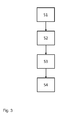
- the embodiment of the inventive method for reversibly fastening side sections to the rear side of a cabin of the tractor using the inventive latching device according to Fig. 3 comprises a step S1 of turning the side section 7 to the rear side 8 of the cabin, so that the wide side of the side section 7 is parallel and in close contact to the rear side 8.
- a second step S2 the first spring 4a that is keeping the pin 3 in the first position is release.
- a third step S3 the pin 3 of the latching device is pushed from the first position into the second position. The pin 3 is then held in the second position by the second spring 4b.
- the pin 3 is secured in the aperture 6 of the skid 5.
- the pin 3 is secured in the aperture by any suitable fixing device, such as additional springs, screws, locks or bars.
- Step S4 also comprises the fixing of the pin 3 in the second position by the second spring 4b.
- the pin 3 is released from the aperture 6 by releasing the fixing devices and releasing the second spring 4b, pushing the pin 3 back into the first position and fixing the pin 3 in the first position by the first spring 4a.
Landscapes
- Engineering & Computer Science (AREA)
- Chemical & Material Sciences (AREA)
- Combustion & Propulsion (AREA)
- Transportation (AREA)
- Mechanical Engineering (AREA)
- Body Structure For Vehicles (AREA)
- Agricultural Machines (AREA)
Description
- The invention is related to a latching device for reversibly fastening a side section of a truck to a structure of a cabin of a tractor of the truck.
- The gap between a tractor and a trailer in a truck, particularly a semi-trailer truck, causes aerodynamic drag and air turbulence which has a negative impact on fuel efficiency and maneuverability, particularly at high speeds. The aerodynamics of such a truck can be improved by a arranging a side section at the rear side of the driver cabin of the tractor. The side section is a kind of an extension of the side of the cabin directing airflow over the sides of the trailer.
- The side sections are usually connected to the cabin by a plurality of hinges. The hinges are built in a way which facilitates a rotation movement of the side sections. The rotation movement of the side sections is useful because that way the side sections are able to effectively direct the airflow while accommodating the relative movement of the tractor and adjacent trailer during a turn. Further, upon connecting or disconnecting the trailer from the tractor, the side sections must be moved so that connecting mechanisms for the trailer become accessible. After the trailer has been connected to the tractor, the side sections are brought back into a position closing the gap between the tractor and the trailer. The side sections are formed to be arranged at the side of the tractor, where they usually are hold in a position by spring loaded panels.
- For the connecting process of the trailer to the tractor the side sections have to be fixed to the rear side of the cabin in order not to interfere with this process. Conventional fastening mechanisms, however, wear out over time by permanent use. This negatively affects the reliability of the fastening mechanisms and also leads to undesired vibrations as wells as to noisy squeaking and rattling of the fastening mechanisms.
- It is the objective of the present invention to provide a fastening mechanism which is more resistant to wearing by intensive use.
- The objective is solved by a latching device with features according to
claim 1. Advantageous further developments of the invention are evident from the dependent claims, the figures and the example. - A first aspect of the invention refers to a latching device for reversibly fastening a side section of a truck to a structure of a tractor of the truck, the latching device comprising
- at least one skid with an aperture mounted to the structure of the tractor,
- at least one sleeve with a sliding rail mounted to the side section,
- a pin that is adapted to slide in the sliding rail, and that passes through the aperture in the skid, and
- at least one spring contained within the sleeve for keeping the pin in at least one predetermined position.
- The latching device is advantageous because its sliding mechanism provides a sophisticated connection of the side section to the tractor. A further advantage of the inventive latching device is a greater long term mechanical stability as compared to conventional fastening mechanisms.
- The term "truck" as used in this description refers to a combination of a tractor and a trailer.
- In a preferred embodiment the sleeve of the latching device is mounted on the side section in a way that the pin can slide into the aperture of the skid.
- It is further preferred if the structure of the tractor is the rear side of a cabin of the tractor. This is advantageous because that way the side sections can be fastened to the rear side of the cabin during connecting or disconnecting operations of a trailer to the tractor.
- The pin of the inventive latching device is preferably kept in a first position by the spring, if the side section is not to be fastened. It is further preferred that the pin of the inventive latching device is kept in a second position by the spring, if the side section is to be fastened.
- It is advantageous if the pin of the inventive latching device is adapted to be moved from the first to the second position by application of manual force. It is also possible to use a suitable tool for moving the pin, or to adapt an additional spring for moving the pin, or to adapt a linear motor.
- A second aspect of the invention is related to a side section of a truck with an inventive latching device. With other words the inventive side section comprised a latching device at least one skid with an aperture, at least one sleeve with a sliding rail mounted to a side section, a sliding pin that is adapted to slide in the sliding rail, and that passes through the aperture in the skid, and at least one spring contained within the sleeve for keeping the pin in at least one predetermined position.
- A third aspect of the invention is related to a tractor with inventive side sections.
- A fourth aspect of the invention is related to a method for reversibly fastening side sections of a rear side of a cabin of a tractor of a truck using an inventive latching device, the method comprising
- turning the side section to the rear side of the cabin,
- releasing a spring that is keeping the pin in a first position,
- moving the pin of the latching device from the first position into the second position,
- securing the pin in the aperture of the skid.
- The advantaged of the inventive method correspond to the advantages of the inventive latching device. For bringing the side section back into a position at the side of the tractor, the steps of fastening the side section are performed in reverse order, namely releasing the pin from the aperture of the skid, pushing the pin from the second into the first position, securing the pin in the first position with the spring and turning the side section from the rear side of the cabin.
- Embodiments of the invention are described in conjunction with the accompanying figures.
- Figure 1
- shows an embodiment of an inventive latching device.
- Figure 2a
- shows a configuration of the latching device according to
Fig. 1 mounted to a side section and rear part of a cabin. - Figure 2b
- shows the configuration of
Fig. 2a with an opened side section - Figure 3
- shows a flow chart of an embodiment of the inventive method.
- A
latching device 1 according to the presentation ofFig. 1 comprises asleeve 2, apin 3 which can slide within a slidingrail 2a of the sleeve in two directions, and afirst spring 4a and asecond spring 4b, which are provided for holding the pin in a first and second position, respectively. Thelatching device 1 further comprises askid 5 that bears anaperture 6 for receiving the pin. Theaperture 6 comprises fixing devices for securing thepin 3, such as additional springs, screws, locks or bars. Thelatching device 1 comprises two parts, wherein a first part comprises thesleeve 2, thepin 3 and thesprings skid 5. - The
latching device 1 has a rectangular appearance. The long sides of the rectangle are parallel to the sliding direction of thepin 3 in the slidingrail 2a. The short sides of the rectangle are perpendicular to the sliding direction of thepin 3, basically limiting the way of thepin 3. - Referring to
Fig. 2a , thelatching device 1 is used to fasten aside section 7 to arear side 8 of a cabin of a tractor. The first part of thelatching device 1 is affixed to theside section 7. The second part of thelatching device 1 is affixed to therear side 8 of a cabin of a tractor. Each first part affixed to theside section 7 has a corresponding second part affixed to therear side 8. The presentation ofFig. 2a shows a number of fourlatching devices 1 fastening theside section 7 to therear side 8 of the cabin. If necessary, however, the number oflatching devices 1 can be higher. - In the representation of
Fig. 2b theside section 7 is opened, so its narrow side is visible. Theskids 5 are affixed to therear side 8 of the cabin. - The embodiment of the inventive method for reversibly fastening side sections to the rear side of a cabin of the tractor using the inventive latching device according to
Fig. 3 comprises a step S1 of turning theside section 7 to therear side 8 of the cabin, so that the wide side of theside section 7 is parallel and in close contact to therear side 8. In a second step S2 thefirst spring 4a that is keeping thepin 3 in the first position is release. In a third step S3 thepin 3 of the latching device is pushed from the first position into the second position. Thepin 3 is then held in the second position by thesecond spring 4b. In a fourth step S4 thepin 3 is secured in theaperture 6 of theskid 5. Thepin 3 is secured in the aperture by any suitable fixing device, such as additional springs, screws, locks or bars. Step S4 also comprises the fixing of thepin 3 in the second position by thesecond spring 4b. - If the
side section 7 is to be disconnected from therear side 8 of the cabin, thepin 3 is released from theaperture 6 by releasing the fixing devices and releasing thesecond spring 4b, pushing thepin 3 back into the first position and fixing thepin 3 in the first position by thefirst spring 4a. - Since various variations of the described embodiments are possible the invention shall only be limited by the scope of the claims.
-
- 1
- = latching device
- 2
- = sleeve
- 2a
- = sliding rail
- 3
- = pin
- 4a
- = first spring
- 4b
- = second spring
- 5
- = skid
- 6
- = aperture
- 7
- = side section
- 8
- = rear side of a cabin
Claims (9)
- A latching device (1) for reversibly fastening a side section (7) of a truck to a structure (8) of a tractor of the truck, the latching device (1) comprising- at least one skid (5) with an aperture (6) mounted to the structure of the tractor,- at least one sleeve (2) with a sliding rail (2a) mounted to the side section (7),- a pin (3) that is adapted to slide in the sliding rail (2a), and that passes through the aperture (6) in the skid (5), and- at least one spring (4a, 4b) comprised by the sleeve (2) for keeping the pin (3) in at least one predetermined position.
- The latching device (1) of claim 1, wherein the sleeve (2) of the latching device (1) is mounted on the side section (7) in a way that the pin (3) can slide into the aperture (6) of the skid (5).
- The latching device (1) of claim 1 or 2, wherein the structure of the tractor is the rear side of a cabin of the tractor.
- The latching device (1) of any of the foregoing claims, wherein the pin (3) is kept in a first position by the spring (4a), if the side section (7) is not to be fastened.
- The latching device (1) of any of the foregoing claims, wherein the pin (3) is kept in a second position by the spring (4b), if the side section (7) is to be fastened.
- The latching device (1) of claim 4, wherein the pin (3) is adapted to be moved from the first to the second position by application of manual force.
- Side section (7) of a truck with a latching device (1) according to any of the claims 1 - 6.
- A truck with side sections according to claim 7.
- Method for reversibly fastening side sections of a truck to the rear side of a cabin of a tractor of the truck using a latching device according to any of claims 1 - 5, the method comprising- turning the side section (7) to the rear side (8) of the cabin,- releasing the first spring (4a) that is keeping the pin (3) in the first position,- moving the pin (3) of the latching device (1) from the first position into the second position,- securing the pin (3) in the aperture (6) of the skid (5).
Priority Applications (2)
| Application Number | Priority Date | Filing Date | Title |
|---|---|---|---|
| EP15176965.0A EP3118090B1 (en) | 2015-07-16 | 2015-07-16 | Latching device for a side section of a truck |
| CN201620749159.8U CN205891023U (en) | 2015-07-16 | 2016-07-15 | Lateral part district section and truck of blocking device , truck |
Applications Claiming Priority (1)
| Application Number | Priority Date | Filing Date | Title |
|---|---|---|---|
| EP15176965.0A EP3118090B1 (en) | 2015-07-16 | 2015-07-16 | Latching device for a side section of a truck |
Publications (2)
| Publication Number | Publication Date |
|---|---|
| EP3118090A1 true EP3118090A1 (en) | 2017-01-18 |
| EP3118090B1 EP3118090B1 (en) | 2018-09-19 |
Family
ID=53785432
Family Applications (1)
| Application Number | Title | Priority Date | Filing Date |
|---|---|---|---|
| EP15176965.0A Active EP3118090B1 (en) | 2015-07-16 | 2015-07-16 | Latching device for a side section of a truck |
Country Status (2)
| Country | Link |
|---|---|
| EP (1) | EP3118090B1 (en) |
| CN (1) | CN205891023U (en) |
Citations (4)
| Publication number | Priority date | Publication date | Assignee | Title |
|---|---|---|---|---|
| US5232260A (en) * | 1992-05-21 | 1993-08-03 | Lippard Fred E | Truck split tailgate apparatus |
| EP1055589A2 (en) * | 1999-04-08 | 2000-11-29 | Steyr-Nutzfahrzeuge Aktiengesellschaft | Support for a roof spoiler on the driver's cab of a truck |
| US20050012344A1 (en) * | 2003-07-15 | 2005-01-20 | Volvo Trucks North America, Inc. | Chassis fairing latch with integral handle |
| FR2933943A1 (en) * | 2008-07-18 | 2010-01-22 | Robert Cadalbert | Removable rear wheel housing fairing for CX type car, has seal or plate whose inner face is provided with disconnecting fixation units gripped on return pipe formed by body at level of contour for locking body covering zone on vehicle body |
-
2015
- 2015-07-16 EP EP15176965.0A patent/EP3118090B1/en active Active
-
2016
- 2016-07-15 CN CN201620749159.8U patent/CN205891023U/en active Active
Patent Citations (4)
| Publication number | Priority date | Publication date | Assignee | Title |
|---|---|---|---|---|
| US5232260A (en) * | 1992-05-21 | 1993-08-03 | Lippard Fred E | Truck split tailgate apparatus |
| EP1055589A2 (en) * | 1999-04-08 | 2000-11-29 | Steyr-Nutzfahrzeuge Aktiengesellschaft | Support for a roof spoiler on the driver's cab of a truck |
| US20050012344A1 (en) * | 2003-07-15 | 2005-01-20 | Volvo Trucks North America, Inc. | Chassis fairing latch with integral handle |
| FR2933943A1 (en) * | 2008-07-18 | 2010-01-22 | Robert Cadalbert | Removable rear wheel housing fairing for CX type car, has seal or plate whose inner face is provided with disconnecting fixation units gripped on return pipe formed by body at level of contour for locking body covering zone on vehicle body |
Also Published As
| Publication number | Publication date |
|---|---|
| EP3118090B1 (en) | 2018-09-19 |
| CN205891023U (en) | 2017-01-18 |
Similar Documents
| Publication | Publication Date | Title |
|---|---|---|
| JP6490722B2 (en) | Slide rail assembly | |
| EP3322269B1 (en) | Bracket device and slide rail assembly comprising the same | |
| CA2623225C (en) | Locator assembly | |
| US9986830B2 (en) | Slide rail assembly for chassis system | |
| DE602006012335D1 (en) | MOUNTING FOR PLANE ENGINE | |
| JP5264903B2 (en) | Locking device for automobile bonnet | |
| JP5068585B2 (en) | Fixing device for mounting parts | |
| CN106594034A (en) | Fastener device | |
| US20100052365A1 (en) | Device for positioning a piece of car body work on a motor vehicle | |
| GB2478414A (en) | Bodyshell of a passenger vehicle with a rear spoiler module | |
| US20150353002A1 (en) | Headlamp retaining bracket assembly | |
| EP3118090B1 (en) | Latching device for a side section of a truck | |
| US7441827B2 (en) | Rear support for a vehicle, a rear module, and a method of securing such a module | |
| WO2008149044A3 (en) | Energy absorption assembly provided with two absorption devices | |
| US11007948B2 (en) | Device connectable to the luggage boot of a motor vehicle for quickly preparing the same to safely transport one or more packages, luggage boot comprising said device and motor vehicle provided with a luggage boot comprising said device | |
| ATE325027T1 (en) | ASSEMBLY METHOD FOR AN MOTOR VEHICLE EQUIPMENT MODULE AND BODY PART, AND ARRANGEMENT FOR SUCH ASSEMBLY | |
| CN105775103B (en) | Door for closing an opening in a structure and aircraft | |
| KR102531101B1 (en) | Apparatus for coupling door trim of vehicle | |
| CN216491544U (en) | Front unlocking rear column lock mechanism | |
| US11104390B2 (en) | Motor vehicle with air-guide and drive | |
| JP3195177U (en) | Slide rail kit | |
| KR20040085401A (en) | Front End Module of Vehicle | |
| KR20090021488A (en) | Fixing clip | |
| CN218431389U (en) | Steering column adjusting handle and vehicle | |
| CN202417079U (en) | Left rear door lock assembly for automobile |
Legal Events
| Date | Code | Title | Description |
|---|---|---|---|
| PUAI | Public reference made under article 153(3) epc to a published international application that has entered the european phase |
Free format text: ORIGINAL CODE: 0009012 |
|
| STAA | Information on the status of an ep patent application or granted ep patent |
Free format text: STATUS: THE APPLICATION HAS BEEN PUBLISHED |
|
| AK | Designated contracting states |
Kind code of ref document: A1 Designated state(s): AL AT BE BG CH CY CZ DE DK EE ES FI FR GB GR HR HU IE IS IT LI LT LU LV MC MK MT NL NO PL PT RO RS SE SI SK SM TR |
|
| AX | Request for extension of the european patent |
Extension state: BA ME |
|
| STAA | Information on the status of an ep patent application or granted ep patent |
Free format text: STATUS: REQUEST FOR EXAMINATION WAS MADE |
|
| 17P | Request for examination filed |
Effective date: 20170718 |
|
| RBV | Designated contracting states (corrected) |
Designated state(s): AL AT BE BG CH CY CZ DE DK EE ES FI FR GB GR HR HU IE IS IT LI LT LU LV MC MK MT NL NO PL PT RO RS SE SI SK SM TR |
|
| INTG | Intention to grant announced |
Effective date: 20180611 |
|
| GRAP | Despatch of communication of intention to grant a patent |
Free format text: ORIGINAL CODE: EPIDOSNIGR1 |
|
| STAA | Information on the status of an ep patent application or granted ep patent |
Free format text: STATUS: GRANT OF PATENT IS INTENDED |
|
| GRAS | Grant fee paid |
Free format text: ORIGINAL CODE: EPIDOSNIGR3 |
|
| GRAA | (expected) grant |
Free format text: ORIGINAL CODE: 0009210 |
|
| STAA | Information on the status of an ep patent application or granted ep patent |
Free format text: STATUS: THE PATENT HAS BEEN GRANTED |
|
| AK | Designated contracting states |
Kind code of ref document: B1 Designated state(s): AL AT BE BG CH CY CZ DE DK EE ES FI FR GB GR HR HU IE IS IT LI LT LU LV MC MK MT NL NO PL PT RO RS SE SI SK SM TR |
|
| REG | Reference to a national code |
Ref country code: GB Ref legal event code: FG4D |
|
| REG | Reference to a national code |
Ref country code: CH Ref legal event code: EP |
|
| REG | Reference to a national code |
Ref country code: AT Ref legal event code: REF Ref document number: 1042928 Country of ref document: AT Kind code of ref document: T Effective date: 20181015 |
|
| REG | Reference to a national code |
Ref country code: IE Ref legal event code: FG4D |
|
| REG | Reference to a national code |
Ref country code: DE Ref legal event code: R096 Ref document number: 602015016495 Country of ref document: DE |
|
| REG | Reference to a national code |
Ref country code: NL Ref legal event code: MP Effective date: 20180919 |
|
| PG25 | Lapsed in a contracting state [announced via postgrant information from national office to epo] |
Ref country code: LT Free format text: LAPSE BECAUSE OF FAILURE TO SUBMIT A TRANSLATION OF THE DESCRIPTION OR TO PAY THE FEE WITHIN THE PRESCRIBED TIME-LIMIT Effective date: 20180919 Ref country code: RS Free format text: LAPSE BECAUSE OF FAILURE TO SUBMIT A TRANSLATION OF THE DESCRIPTION OR TO PAY THE FEE WITHIN THE PRESCRIBED TIME-LIMIT Effective date: 20180919 Ref country code: FI Free format text: LAPSE BECAUSE OF FAILURE TO SUBMIT A TRANSLATION OF THE DESCRIPTION OR TO PAY THE FEE WITHIN THE PRESCRIBED TIME-LIMIT Effective date: 20180919 Ref country code: GR Free format text: LAPSE BECAUSE OF FAILURE TO SUBMIT A TRANSLATION OF THE DESCRIPTION OR TO PAY THE FEE WITHIN THE PRESCRIBED TIME-LIMIT Effective date: 20181220 Ref country code: BG Free format text: LAPSE BECAUSE OF FAILURE TO SUBMIT A TRANSLATION OF THE DESCRIPTION OR TO PAY THE FEE WITHIN THE PRESCRIBED TIME-LIMIT Effective date: 20181219 Ref country code: NO Free format text: LAPSE BECAUSE OF FAILURE TO SUBMIT A TRANSLATION OF THE DESCRIPTION OR TO PAY THE FEE WITHIN THE PRESCRIBED TIME-LIMIT Effective date: 20181219 Ref country code: SE Free format text: LAPSE BECAUSE OF FAILURE TO SUBMIT A TRANSLATION OF THE DESCRIPTION OR TO PAY THE FEE WITHIN THE PRESCRIBED TIME-LIMIT Effective date: 20180919 |
|
| REG | Reference to a national code |
Ref country code: LT Ref legal event code: MG4D |
|
| PG25 | Lapsed in a contracting state [announced via postgrant information from national office to epo] |
Ref country code: HR Free format text: LAPSE BECAUSE OF FAILURE TO SUBMIT A TRANSLATION OF THE DESCRIPTION OR TO PAY THE FEE WITHIN THE PRESCRIBED TIME-LIMIT Effective date: 20180919 Ref country code: LV Free format text: LAPSE BECAUSE OF FAILURE TO SUBMIT A TRANSLATION OF THE DESCRIPTION OR TO PAY THE FEE WITHIN THE PRESCRIBED TIME-LIMIT Effective date: 20180919 Ref country code: AL Free format text: LAPSE BECAUSE OF FAILURE TO SUBMIT A TRANSLATION OF THE DESCRIPTION OR TO PAY THE FEE WITHIN THE PRESCRIBED TIME-LIMIT Effective date: 20180919 |
|
| REG | Reference to a national code |
Ref country code: AT Ref legal event code: MK05 Ref document number: 1042928 Country of ref document: AT Kind code of ref document: T Effective date: 20180919 |
|
| PG25 | Lapsed in a contracting state [announced via postgrant information from national office to epo] |
Ref country code: CZ Free format text: LAPSE BECAUSE OF FAILURE TO SUBMIT A TRANSLATION OF THE DESCRIPTION OR TO PAY THE FEE WITHIN THE PRESCRIBED TIME-LIMIT Effective date: 20180919 Ref country code: RO Free format text: LAPSE BECAUSE OF FAILURE TO SUBMIT A TRANSLATION OF THE DESCRIPTION OR TO PAY THE FEE WITHIN THE PRESCRIBED TIME-LIMIT Effective date: 20180919 Ref country code: ES Free format text: LAPSE BECAUSE OF FAILURE TO SUBMIT A TRANSLATION OF THE DESCRIPTION OR TO PAY THE FEE WITHIN THE PRESCRIBED TIME-LIMIT Effective date: 20180919 Ref country code: IS Free format text: LAPSE BECAUSE OF FAILURE TO SUBMIT A TRANSLATION OF THE DESCRIPTION OR TO PAY THE FEE WITHIN THE PRESCRIBED TIME-LIMIT Effective date: 20190119 Ref country code: NL Free format text: LAPSE BECAUSE OF FAILURE TO SUBMIT A TRANSLATION OF THE DESCRIPTION OR TO PAY THE FEE WITHIN THE PRESCRIBED TIME-LIMIT Effective date: 20180919 Ref country code: PL Free format text: LAPSE BECAUSE OF FAILURE TO SUBMIT A TRANSLATION OF THE DESCRIPTION OR TO PAY THE FEE WITHIN THE PRESCRIBED TIME-LIMIT Effective date: 20180919 Ref country code: IT Free format text: LAPSE BECAUSE OF FAILURE TO SUBMIT A TRANSLATION OF THE DESCRIPTION OR TO PAY THE FEE WITHIN THE PRESCRIBED TIME-LIMIT Effective date: 20180919 Ref country code: EE Free format text: LAPSE BECAUSE OF FAILURE TO SUBMIT A TRANSLATION OF THE DESCRIPTION OR TO PAY THE FEE WITHIN THE PRESCRIBED TIME-LIMIT Effective date: 20180919 Ref country code: AT Free format text: LAPSE BECAUSE OF FAILURE TO SUBMIT A TRANSLATION OF THE DESCRIPTION OR TO PAY THE FEE WITHIN THE PRESCRIBED TIME-LIMIT Effective date: 20180919 |
|
| PG25 | Lapsed in a contracting state [announced via postgrant information from national office to epo] |
Ref country code: SM Free format text: LAPSE BECAUSE OF FAILURE TO SUBMIT A TRANSLATION OF THE DESCRIPTION OR TO PAY THE FEE WITHIN THE PRESCRIBED TIME-LIMIT Effective date: 20180919 Ref country code: SK Free format text: LAPSE BECAUSE OF FAILURE TO SUBMIT A TRANSLATION OF THE DESCRIPTION OR TO PAY THE FEE WITHIN THE PRESCRIBED TIME-LIMIT Effective date: 20180919 Ref country code: PT Free format text: LAPSE BECAUSE OF FAILURE TO SUBMIT A TRANSLATION OF THE DESCRIPTION OR TO PAY THE FEE WITHIN THE PRESCRIBED TIME-LIMIT Effective date: 20190119 |
|
| REG | Reference to a national code |
Ref country code: DE Ref legal event code: R097 Ref document number: 602015016495 Country of ref document: DE |
|
| PLBE | No opposition filed within time limit |
Free format text: ORIGINAL CODE: 0009261 |
|
| STAA | Information on the status of an ep patent application or granted ep patent |
Free format text: STATUS: NO OPPOSITION FILED WITHIN TIME LIMIT |
|
| PG25 | Lapsed in a contracting state [announced via postgrant information from national office to epo] |
Ref country code: DK Free format text: LAPSE BECAUSE OF FAILURE TO SUBMIT A TRANSLATION OF THE DESCRIPTION OR TO PAY THE FEE WITHIN THE PRESCRIBED TIME-LIMIT Effective date: 20180919 |
|
| 26N | No opposition filed |
Effective date: 20190620 |
|
| PGFP | Annual fee paid to national office [announced via postgrant information from national office to epo] |
Ref country code: FR Payment date: 20190621 Year of fee payment: 5 |
|
| PG25 | Lapsed in a contracting state [announced via postgrant information from national office to epo] |
Ref country code: SI Free format text: LAPSE BECAUSE OF FAILURE TO SUBMIT A TRANSLATION OF THE DESCRIPTION OR TO PAY THE FEE WITHIN THE PRESCRIBED TIME-LIMIT Effective date: 20180919 |
|
| PGFP | Annual fee paid to national office [announced via postgrant information from national office to epo] |
Ref country code: GB Payment date: 20190626 Year of fee payment: 5 |
|
| PG25 | Lapsed in a contracting state [announced via postgrant information from national office to epo] |
Ref country code: MC Free format text: LAPSE BECAUSE OF FAILURE TO SUBMIT A TRANSLATION OF THE DESCRIPTION OR TO PAY THE FEE WITHIN THE PRESCRIBED TIME-LIMIT Effective date: 20180919 |
|
| REG | Reference to a national code |
Ref country code: CH Ref legal event code: PL |
|
| REG | Reference to a national code |
Ref country code: BE Ref legal event code: MM Effective date: 20190731 |
|
| PG25 | Lapsed in a contracting state [announced via postgrant information from national office to epo] |
Ref country code: CH Free format text: LAPSE BECAUSE OF NON-PAYMENT OF DUE FEES Effective date: 20190731 Ref country code: BE Free format text: LAPSE BECAUSE OF NON-PAYMENT OF DUE FEES Effective date: 20190731 Ref country code: LU Free format text: LAPSE BECAUSE OF NON-PAYMENT OF DUE FEES Effective date: 20190716 Ref country code: LI Free format text: LAPSE BECAUSE OF NON-PAYMENT OF DUE FEES Effective date: 20190731 |
|
| PG25 | Lapsed in a contracting state [announced via postgrant information from national office to epo] |
Ref country code: IE Free format text: LAPSE BECAUSE OF NON-PAYMENT OF DUE FEES Effective date: 20190716 |
|
| GBPC | Gb: european patent ceased through non-payment of renewal fee |
Effective date: 20200716 |
|
| PG25 | Lapsed in a contracting state [announced via postgrant information from national office to epo] |
Ref country code: GB Free format text: LAPSE BECAUSE OF NON-PAYMENT OF DUE FEES Effective date: 20200716 Ref country code: FR Free format text: LAPSE BECAUSE OF NON-PAYMENT OF DUE FEES Effective date: 20200731 |
|
| PG25 | Lapsed in a contracting state [announced via postgrant information from national office to epo] |
Ref country code: CY Free format text: LAPSE BECAUSE OF FAILURE TO SUBMIT A TRANSLATION OF THE DESCRIPTION OR TO PAY THE FEE WITHIN THE PRESCRIBED TIME-LIMIT Effective date: 20180919 |
|
| PG25 | Lapsed in a contracting state [announced via postgrant information from national office to epo] |
Ref country code: MT Free format text: LAPSE BECAUSE OF FAILURE TO SUBMIT A TRANSLATION OF THE DESCRIPTION OR TO PAY THE FEE WITHIN THE PRESCRIBED TIME-LIMIT Effective date: 20180919 Ref country code: HU Free format text: LAPSE BECAUSE OF FAILURE TO SUBMIT A TRANSLATION OF THE DESCRIPTION OR TO PAY THE FEE WITHIN THE PRESCRIBED TIME-LIMIT; INVALID AB INITIO Effective date: 20150716 |
|
| PG25 | Lapsed in a contracting state [announced via postgrant information from national office to epo] |
Ref country code: MK Free format text: LAPSE BECAUSE OF FAILURE TO SUBMIT A TRANSLATION OF THE DESCRIPTION OR TO PAY THE FEE WITHIN THE PRESCRIBED TIME-LIMIT Effective date: 20180919 |
|
| P01 | Opt-out of the competence of the unified patent court (upc) registered |
Effective date: 20230625 |
|
| PGFP | Annual fee paid to national office [announced via postgrant information from national office to epo] |
Ref country code: TR Payment date: 20250625 Year of fee payment: 11 |
|
| PGFP | Annual fee paid to national office [announced via postgrant information from national office to epo] |
Ref country code: DE Payment date: 20250616 Year of fee payment: 11 |