EP3118006A2 - Image erasing apparatus and image erasing method - Google Patents
Image erasing apparatus and image erasing method Download PDFInfo
- Publication number
- EP3118006A2 EP3118006A2 EP16178065.5A EP16178065A EP3118006A2 EP 3118006 A2 EP3118006 A2 EP 3118006A2 EP 16178065 A EP16178065 A EP 16178065A EP 3118006 A2 EP3118006 A2 EP 3118006A2
- Authority
- EP
- European Patent Office
- Prior art keywords
- image
- sheet
- unit
- erasing
- identification information
- Prior art date
- Legal status (The legal status is an assumption and is not a legal conclusion. Google has not performed a legal analysis and makes no representation as to the accuracy of the status listed.)
- Granted
Links
Images

Classifications
-
- B—PERFORMING OPERATIONS; TRANSPORTING
- B41—PRINTING; LINING MACHINES; TYPEWRITERS; STAMPS
- B41J—TYPEWRITERS; SELECTIVE PRINTING MECHANISMS, i.e. MECHANISMS PRINTING OTHERWISE THAN FROM A FORME; CORRECTION OF TYPOGRAPHICAL ERRORS
- B41J2/00—Typewriters or selective printing mechanisms characterised by the printing or marking process for which they are designed
- B41J2/315—Typewriters or selective printing mechanisms characterised by the printing or marking process for which they are designed characterised by selective application of heat to a heat sensitive printing or impression-transfer material
- B41J2/32—Typewriters or selective printing mechanisms characterised by the printing or marking process for which they are designed characterised by selective application of heat to a heat sensitive printing or impression-transfer material using thermal heads
-
- B—PERFORMING OPERATIONS; TRANSPORTING
- B41—PRINTING; LINING MACHINES; TYPEWRITERS; STAMPS
- B41M—PRINTING, DUPLICATING, MARKING, OR COPYING PROCESSES; COLOUR PRINTING
- B41M7/00—After-treatment of prints, e.g. heating, irradiating, setting of the ink, protection of the printed stock
- B41M7/0009—Obliterating the printed matter; Non-destructive removal of the ink pattern, e.g. for repetitive use of the support
-
- G—PHYSICS
- G06—COMPUTING OR CALCULATING; COUNTING
- G06K—GRAPHICAL DATA READING; PRESENTATION OF DATA; RECORD CARRIERS; HANDLING RECORD CARRIERS
- G06K15/00—Arrangements for producing a permanent visual presentation of the output data, e.g. computer output printers
- G06K15/02—Arrangements for producing a permanent visual presentation of the output data, e.g. computer output printers using printers
- G06K15/16—Means for paper feeding or form feeding
-
- G—PHYSICS
- G06—COMPUTING OR CALCULATING; COUNTING
- G06K—GRAPHICAL DATA READING; PRESENTATION OF DATA; RECORD CARRIERS; HANDLING RECORD CARRIERS
- G06K15/00—Arrangements for producing a permanent visual presentation of the output data, e.g. computer output printers
- G06K15/40—Details not directly involved in printing, e.g. machine management, management of the arrangement as a whole or of its constitutive parts
- G06K15/4025—Managing optional units, e.g. sorters, document feeders
-
- G—PHYSICS
- G06—COMPUTING OR CALCULATING; COUNTING
- G06K—GRAPHICAL DATA READING; PRESENTATION OF DATA; RECORD CARRIERS; HANDLING RECORD CARRIERS
- G06K15/00—Arrangements for producing a permanent visual presentation of the output data, e.g. computer output printers
- G06K15/40—Details not directly involved in printing, e.g. machine management, management of the arrangement as a whole or of its constitutive parts
- G06K15/4095—Secure printing
-
- H—ELECTRICITY
- H04—ELECTRIC COMMUNICATION TECHNIQUE
- H04N—PICTORIAL COMMUNICATION, e.g. TELEVISION
- H04N1/00—Scanning, transmission or reproduction of documents or the like, e.g. facsimile transmission; Details thereof
- H04N1/00795—Reading arrangements
-
- H—ELECTRICITY
- H04—ELECTRIC COMMUNICATION TECHNIQUE
- H04N—PICTORIAL COMMUNICATION, e.g. TELEVISION
- H04N1/00—Scanning, transmission or reproduction of documents or the like, e.g. facsimile transmission; Details thereof
- H04N1/00795—Reading arrangements
- H04N1/00798—Circuits or arrangements for the control thereof, e.g. using a programmed control device or according to a measured quantity
- H04N1/00801—Circuits or arrangements for the control thereof, e.g. using a programmed control device or according to a measured quantity according to characteristics of the original
- H04N1/00803—Presence or absence of information
-
- B—PERFORMING OPERATIONS; TRANSPORTING
- B41—PRINTING; LINING MACHINES; TYPEWRITERS; STAMPS
- B41J—TYPEWRITERS; SELECTIVE PRINTING MECHANISMS, i.e. MECHANISMS PRINTING OTHERWISE THAN FROM A FORME; CORRECTION OF TYPOGRAPHICAL ERRORS
- B41J2202/00—Embodiments of or processes related to ink-jet or thermal heads
- B41J2202/30—Embodiments of or processes related to thermal heads
- B41J2202/37—Writing and erasing thermal head
Definitions
- Embodiments described herein relate generally to an apparatus.
- a reading unit reads identification information formed on a sheet conveyed.
- the erasing unit is provided at a downstream side with respect to the reading unit in a conveying direction of the sheet.
- the erasing unit erases a part or all of a first image formed on the sheet.
- the image forming unit is provided at a downstream side with respect to the erasing unit in the conveying direction of the sheet.
- the image forming unit forms an image on the sheet from which the erasing unit has erased the first image.
- the controller obtains image data corresponding to the identification information that is read by the reading unit.
- the controller controls the image forming unit so that a second image indicated by the obtained image data is formed on the sheet from which the first image has been erased.
- the controller controls the reading unit to read identification information formed on the sheet conveyed.
- the image erasing apparatus further includes a user authentication unit carrying out individual authentication based on individual authentication information about a user.
- the controller controls the reading unit so as to read identification information formed on the sheet conveyed.
- the controller controls the erasing unit so as to erase the first image formed on the sheet after the reading unit reads the identification information.
- the image erasing apparatus further includes a storage unit storing in advance the image data of the second image in association with the identification information.
- the controller obtains, from the storage unit, image data corresponding to the identification information that is read by the reading unit.
- the image erasing apparatus further includes a notification unit notifying that an error has occurred when the image data associated with the identification information that is read by the reading unit is not stored in the storage unit.
- image data corresponding to the identification information is image data indicating the second image partially identical to the first image.
- the controller controls the erasing unit so as to erase only a part of an image identical to the second image indicated by the image data corresponding to the identification information in the first image formed on the sheet.
- the controller controls the image forming unit so as to form the second image on the sheet from which the erasing has been completed.
- the controller controls the erasing unit to erase all of the first image formed on the sheet, and the controller controls the image forming unit so as to form the second image on the sheet from which the erasing has been completed.
- the image data corresponding to the identification information is image data indicating the second image different from the first image.
- the controller controls the erasing unit so as to erase a part of the first image formed on the sheet.
- the controller controls the image forming unit so as to form the second image on the sheet from which the erasing has been completed.
- the present invention further relates to an image erasing method comprising: reading identification information formed on a sheet conveyed; erasing a part or all of a first image formed on the sheet after reading the identification information; obtaining image data corresponding to the identification information that has been read; and forming second image, which is based on the obtained image data, onto the sheet from which the first image has been erased.
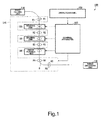
- Fig. 1 is a figure illustrating an example of a schematic configuration of an image erasing apparatus 100 according to the embodiment.
- the image erasing apparatus 100 reads unique identification information 3 formed on a sheet S, and thereafter, erases an original first image 2 formed on the sheet S.
- the image erasing apparatus 100 forms a second image, which is associated with the read identification information 3, onto the sheet S from which the first image 2 has been erased.
- the sheet S is a paper medium on which an image (character, picture, figure, and the like) can be formed.
- the sheet S is a ticket used in an event and the like will be explained for example.
- a sheet S having a first image 2 see Fig.
- first sheet S1 A sheet S having a final image 4 including the second image (see Fig. 3 ) formed therein may be referred to as a second sheet S2.
- the first sheet S1 and the second sheet S2 are the same sheets S, and the difference therebetween lies in the images formed on the sheets S.
- the first sheet S1 is changed into the second sheet S2 by changing the content of the image of the sheet S (description content) by using the image erasing apparatus 100 according to the embodiment.
- the first image 2 of the first sheet S1 may be formed by an apparatus different from the image erasing apparatus 100, or may be formed by the image erasing apparatus 100.
- erasing processing erasing a formed image by using a color agent that can be decolorized with heat will be explained as an example of erasing processing.
- the image erasing apparatus 100 applies decolorization processing for erasing the color of the image by applying heat of a predetermined temperature (which will be hereinafter referred to as a decolorization temperature or a target temperature) or more to the first sheet S1 having an image formed thereon with a color-erasable color agent, i.e., a color-erasable toner, a color-erasable ink, or the like.
- a color-erasable color agent includes a color reaction chemical compound, a developing agent, and an erasing agent.
- An example of a color reaction chemical compound includes leuco dye.
- An example of a developing agent includes phenols.
- the erasing agent When the erasing agent is heated, the erasing agent includes a substance that is compatible with the color reaction chemical compound but does not have compatibility with the developing agent.
- the color-erasable color agent develops color due to interaction between the color reaction chemical compound and the developing agent, and when heated to a decolorization temperature or higher, the interaction between the color reaction chemical compound and the developing agent is eliminated, so that the color-erasable color agent is decolorized.
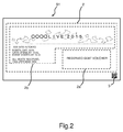
- Fig. 2 is a figure illustrating an example of the first sheet S1 according to the embodiment.
- the first sheet S1 includes a first image 2 and an identification information 3.
- the first image 2 is an image formed with a color-erasable color agent.
- the first image 2 is an image including information related to reserved-seat voucher for a ticket of an event and the like. More specifically, for example, the first image 2 includes an image of a character string "XXX site in Tokyo" as information about the location of the event. Further, the first image 2 includes an image of a character string "Month, day, 2015, gate opens at 15:00, event starts at 16:00, all seats reserved, 7300 Japanese Yen" as information about a date and time and the like.
- the first image 2 includes an image of a character string "reserved-seat voucher" as information indicating that the first sheet S1 is a reserved-seat voucher.
- the image to be erased is not limited to the entire first image 2.
- a part of the first image 2 may be erased by the image erasing apparatus 100.
- the final image 4 and the second image are the same image. Therefore, in the following explanation about the present embodiment, the second image may be referred to as a second image 4.
- the identification information 3 is identification information indicating a unique identifier allocated to each sheet S.
- the identification information 3 is identification information identifying the sheet S or the user of the sheet S.
- the identification information 3 is formed on the sheet S as an image of a QR code (registered trademark), a two-dimensional code, or the like.
- the identification information 3 may be an image formed with a color-erasable color agent, or may be an image formed with a decolorization-impossible color agent.
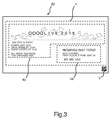
- Fig. 3 is a figure illustrating an example of a second sheet S2 according to the embodiment.
- the second sheet S2 includes the final image 4 (second image 4) and identification information 3.
- the image data of the second image 4 is associated with the identification information 3, and is stored in advance in an image storage area 190 of a storage unit 193 explained later.
- the storage unit 193 explained later previously stores the image data of the second image 4 and the identification information 3 associated with the image data.
- the first image 2 on the first sheet S1 is erased by the image erasing apparatus 100 and thereafter the second image 4 is formed on the sheet S by the image erasing apparatus 100.
- the second image 4 may be an image formed with a color-erasable color agent, or may be an image formed with a decolorization-impossible color agent.
- the second image 4 is an image including information about the reserved-seat ticket for the ticket of the event and the like. More specifically, for example, the second image 4 includes the image of the character string "XXX site in Tokyo" as the information about the location of the event. Furthermore, the second image 4 includes the image of the character string "Month, day, 2015, gate opens at 15:00, event starts at 16:00, all seats reserved, 7300 Japanese Yen" as the information about the date and time and the like.
- the second image 4 includes the image of the character string "reserved-seat ticket” as information indicating that the second sheet S2 is a reserved-seat ticket. Still more, the second image 4 includes an image of a character string "South stand, first floor, F row, seat 30, Mr./Ms. xxx" as information about the location of the seat and the individual name.
- the identification information 3 may be formed with a color-erasable color agent, and may be erased at the same time as when the first image 2 is erased.
- the image erasing apparatus 100 reads the identification information 3, and thereafter, carries out the erasing processing of the first image 2 and the identification information 3.
- the first image 2 and the second image 4 may be completely different images, or may be images at least a portion of which is different.
- the first image 2 includes a partial image 2a and a partial image 2b.
- the second image 4 includes a partial image 4a and a partial image 4b.
- the partial image 2a and the partial image 4a are images different from each other.
- the partial image 2b and the partial image 4b are images different from each other. More specifically, the first image 2 and the second image 4 are partially different images. In other words, the first image 2 and the second image 4 are partially same images.
- the image erasing apparatus 100 includes a sheet feeding unit 110, a conveying unit 115, a reading unit 120, an erasing unit 130, an image forming unit 140, an operation panel 150, a sheet discharge unit 170, and a control apparatus 180.
- the sheet feeding unit 110 feeds the sheet S having the first image 2 and the identification information 3 formed thereon into the inside of the image erasing apparatus 100.
- the sheet feeding unit 110 includes feeding ports, pickup rollers, and the like with which the sheet S is fed.
- the sheet S having the first image 2 and the identification information 3 formed thereon is fed by the user into the sheet feeding unit 110.
- the sheet feeding unit 110 may have a tray on which the sheet S is placed. In this case, the sheet S having the first image 2 and the identification information 3 formed thereon is placed on the tray by the user.
- the conveying unit 115 includes rollers R1 to R5 and a conveying path D for conveying the sheet S.
- the roller R1 is, for example, a pair of a driving roller and a driven roller.
- Each of the rollers R2 to R5 has the same configuration as the roller R1.
- the sheet S is conveyed from the sheet feeding unit 110 to the sheet discharge unit 170, and accordingly, the side of the sheet feeding unit 110 will be referred to as an upstream side in the conveying direction of the sheet S, and the side of the sheet discharge unit 170 will be referred to as a downstream side in the conveying direction of the sheet S.
- the sheet S fed by the sheet feeding unit 110 is conveyed by the conveying unit 115 to the reading unit 120 provided at the downstream side with respect to the sheet feeding unit 110.
- the reading unit 120 includes an optical scanning system.
- the optical scanning system includes imaging devices such as a CCD (Charge Coupled Devices) or a CIS (Contact Image Sensor).
- the scanning optical system includes multiple imaging devices.
- the imaging devices are arranged in one-dimensional or two-dimensional array forms.
- the reading unit 120 scans the sheet S fed from the sheet feeding unit 110 via the roller R1, and reads the identification information 3 of the sheet S.
- the reading unit 120 outputs the read identification information 3 to the control apparatus 180 based on a command of a controller 191 explained later.
- the read identification information 3 is stored to the storage unit 193 explained later.
- the sheet S from which the identification information 3 is read by the reading unit 120 is conveyed by the conveying unit 115 to the erasing unit 130 provided at the downstream side with respect to the reading unit 120.
- the erasing unit 130 includes a pair of rollers and a heater serving as a heating source.
- the heater is provided in at least one of the pair of rollers. Then, the pair of rollers is heated by the heater.
- the erasing unit 130 heats the first image 2 of the sheet S to a decolorization temperature (target temperature) via the pair of rollers heated by the heater.
- the first image 2 explained above is formed using the color-erasable toner with heating.
- the erasing unit 130 decolorizes the color-erasable toner of the first image 2 by heating the first image 2 of the sheet S.
- a temperature sensor is provided in proximity to the pair of rollers. The temperature sensor measures the temperature of the pair of rollers, and transmits a measurement result to the control apparatus 180 explained later.
- the heating source may be a heater and the like using an IH (Induction Heating) technique.
- the image forming unit 140 is provide at the downstream side with respect to the erasing unit 130.
- the image forming unit 140 forms the second image 4 onto the sheet S, which is fed from the erasing unit 130 via the roller R2, based on the image data of the second image 4.
- the image data of the second image 4 is image data associated with the identification information 3 formed on the sheet S.
- the image forming unit 140 includes a well-known printer and a well-known fixing unit.
- the printer forms the second image 4 on, for example, an image carrier in accordance with the image data of the second image 4 transmitted from the control apparatus 180, and transfers the second image 4 from the image carrier to the sheet S.
- the fixing unit applies a predetermined temperature and pressure to the sheet S and fixes the second image 4, which is transferred to the sheet S, onto the sheet S.
- the second image 4 formed by the printer may be a color image or a monochrome image.
- the toner used to form the second image 4 may be an erasable toner or a non-erasable toner.
- the sheet discharge unit 170 is a discharge port of the sheet S having the second image 4 formed thereon.
- the sheet S having the second image 4 formed thereon is retrieved by the user from the sheet discharge unit 170.
- the image erasing apparatus 100 reads the identification information 3 formed on the sheet S that has been fed. Then, the image erasing apparatus 100 erases the first image 2 formed on the sheet S.
- the image erasing apparatus 100 forms the second image 4 corresponding to the read identification information 3 onto the sheet S from which the first image 2 has been erased.
- the image erasing apparatus 100 discharges the sheet S having the second image 4 formed thereon to the sheet discharge unit 170. Therefore, the identical sheet S can be changed from a status in which the first image 2 is formed into a status in which the second image 4 corresponding to the identification information 3 is formed.
- the operation panel 150 generates an activation request signal in accordance with user's operation.
- the activation request signal is a signal indicating a content of processing of reading, decolorization, image forming, and the like.
- the operation panel 150 has a display unit and an operation unit.
- the display unit and operation unit is a touch panel type liquid crystal display. It should be noted that the display unit and the operation unit may be separate apparatuses.
- the operation unit may not be a touch panel type and may be a push type button, a dial type button, or the like.
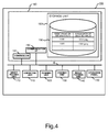
- Fig. 4 is a figure illustrating an example of the configuration of the control apparatus 180 according to the embodiment. It should be noted that functional units and apparatuses possessed by the image erasing apparatus 100 are connected via an internal bus IB and the like, and can input and output data with each other.
- the control apparatus 180 includes the controller 191, a communication interface (communication I/F) 192 and the storage unit 193.
- a CPU Central Processing Unit
- ROM Read Only Memory
- RAM Random Access Memory
- the communication I/F 192 is an interface connected to an external device.
- the communication I/F 192 communicates with an external apparatus, for example, a server, wirelessly or via a wire.
- the communication I/F 192 may include a USB connection unit connected to a connection terminal of USB standard, a parallel interface, and the like.
- the storage unit 193 stores the identification information 3, the image data of the second image 4, threshold value of the heating temperature of the erasing unit 130 or the image forming unit 140, and information such as an activation request signal.
- the storage unit 193 is a nonvolatile memory such as an HDD (Hard Disc Drive), an SSD (Solid State Drive), an EEPROM (Electrically Erasable and Programmable Read-Only Memory), and a flash memory. It should be noted that the storage unit 193 may not be the one that is embedded in the control apparatus 180 and may be an external type nonvolatile storage unit.
- the storage unit 193 includes an image storage area 190.
- the image storage area 190 associates and stores the identification information 3 and the image data of the second image 4.
- the controller 191 obtains, from the image storage area 190, the image data of the second image 4 corresponding to the obtained identification information 3.
- the controller 191 uses the image forming unit 140 to erase the first image 2 of the sheet S, and thereafter, controls the image erasing apparatus 100 so as to print the second image 4 onto the sheet S based on the obtained image data of the second image 4.
- this image storage area 190 may be in a server outside of the image erasing apparatus 100. In this case, the controller 191 accesses the image storage area 190 in the external server via the communication I/F 192.
- the image erasing apparatus 100 as described above executes image forming operation as illustrated in Fig. 5 based on a program set in advance.
- the erasing unit 130 is considered to have attained a temperature at which the image of the sheet S can be erased in accordance with the control of the controller 191.
- the controller 191 controls the sheet feeding unit 110.
- the sheet feeding unit 110 is controlled by the controller 191, so that the sheet S that has been fed is fed in the inside of the main body of the image erasing apparatus 100.
- the controller 191 controls the roller R1 of the conveying unit 115.
- the conveying unit 115 uses the roller R1 controlled by the controller 191 to convey the sheet S into the reading unit 120.
- the controller 191 controls the reading unit 120.
- the reading unit 120 is controlled by the controller 191, so that the reading unit 120 scans the sheet S, and reads the identification information 3.
- the reading unit 120 transmits the read identification information 3 to the control apparatus 180.
- the controller 191 temporarily stores the identification information 3 into a predetermined temporary storage area of the storage unit 193. Further, after the identification information 3 is temporarily stored, the controller 191 controls the conveying unit 115 so that the conveying unit 115 conveys the sheet S to the erasing unit 130.
- the controller 191 controls heating of the pair of rollers with a heater so that the pair of rollers of the erasing unit 130 attain a predetermined temperature or more. Then, the sheet S that has been conveyed is heated by the pair of rollers that are kept at a predetermined temperature or more with the heater. The toner of the first image 2 formed on the sheet S is heated to a decolorization temperature with the pair of rollers. The first image 2 formed on the sheet S is heated to the decolorization temperature so that the first image 2 formed on the sheet S is erased.
- the controller 191 reads the identification information 3 from the temporary storage area of the storage unit 193. Further, the controller 191 searches the image storage area 190 to find the identification information 3 that is read from the temporary storage area. As a result of this search, in a case where the image storage area 190 stores the identification information 3 matching the read identification information 3, the controller 191 obtains, from the image storage area 190, the image data of the second image 4 corresponding to this identification information 3.
- the controller 191 controls the image forming unit 140.
- the image forming unit 140 is controlled by the controller 191, so that the image forming unit 140 forms the second image 4 (final image) on the sheet S based on the image data of the second image 4 obtained in ACT 104.
- the controller 191 controls the conveying unit 115.
- the conveying unit 115 is controlled by the controller 191, so that the conveying unit 115 discharges the sheet S having the second image 4 formed thereon to the sheet discharge unit 170.
- the image erasing apparatus 100 reads the identification information 3 formed on the sheet S, and thereafter, erases the original first image 2 formed on the sheet S.
- the image erasing apparatus 100 forms the final image including the second image 4 onto the sheet S from which the first image 2 has been erased based on the image data of the second image 4 associated with the read identification information 3. Therefore, a new sheet is not required in a case where information different from the information described on the predetermined sheet S is required to be presented to the user. Therefore, according to the present embodiment, the cost of the sheet can be suppressed.
- the image erasing apparatus 100 forms, on the sheet S, the second image 4 in a region where the first image 2 has been erased.
- the sheet S it is not necessary to allocate a region for forming the second image 4 in addition to the region where the first image 2 is formed. More specifically, on the sheet S, it is stuffiest to have a region for forming only the first image 2. Therefore, in a case where information different from the information described on the predetermined sheet S is required to be presented to the user by using the sheet S, it is not necessary to use a sheet S having a large size. Therefore, the user can carry the sheet S without pain.
- the image erasing apparatus 100 may have a notification unit which notifies an occurrence of an error to the user in a case where an error occurs in acquisition of the image data of the second image 4 and formation of the second image 4.
- the notification unit notifies an occurrence of an error to the user.
- the notification unit may notify an error by turning on or blinking a display lamp (not shown) provided in the image erasing apparatus 100.
- the notification unit may notify an error by outputting an audio message or buzzer sound from an audio device (not shown) provided in the image erasing apparatus 100.
- the audio device may alternately generate an audio message and a buzzer sound.
- the audio device is a buzzer or a speaker.
- the notification unit may notify an error by outputting an error message to the display unit of the operation panel 150.
- the image erasing apparatus 100 may have a user authentication unit for authenticating the user.
- the user authentication unit carries out the individual authentication of the user based on the individual authentication information of the user read by the image erasing apparatus 100. For example, the user authentication unit carries out the individual authentication by comparing and collating the individual authentication information about the user with the authentication information stored in a database, not shown. In a case where the read individual authentication information matches the authentication information stored in the storage unit, not shown, the user authentication unit determines that the individual authentication is successfully completed. In a case where the individual authentication performed with the user authentication unit is successful, the image erasing apparatus 100 starts reading the identification information 3 of the sheet S.
- the user authentication unit is a face authentication unit, a biometric authentication unit, or a card reader.
- the face authentication unit reads a feature of the face of the user as individual authentication information.
- the biometric authentication unit reads a biometric feature of a palm, a finger, or the like of the user as individual authentication information.
- the card reader reads individual authentication information stored in an ID card and the like possessed by the user. Therefore, the image erasing apparatus 100 can perform identification to confirm that the user has legally purchased a ticket of an event of a concert, a live show, or the like. Therefore, according to the modification of the embodiment explained above, after the identification is completed, the ticket having the second image 4 formed thereon is discharged from the image erasing apparatus 100, and therefore, the image erasing apparatus 100 having a high degree of security can be provided.
- the image erasing apparatus 100 may form the second image 4 and new identification information on the sheet S.
- the image erasing apparatus 100 erases all the first image 2 (see Fig. 2 ) formed on the sheet S1, but the image erasing apparatus 100 according to the embodiment is not limited thereto.
- the image erasing apparatus 100 may erase a part of the first image 2 as illustrated in Fig. 2 formed on the sheet S.
- the image erasing apparatus 100 may erase, as a part of the first image 2, only the partial image 2a as illustrated in Fig. 2 .
- the image erasing apparatus 100 may leave only the partial image 2b without erasing it.
- the image erasing apparatus 100 in association with the identification information 3, the image erasing apparatus 100 previously stores, as image data of the second image, image data of the partial image 4a as illustrated in Fig. 3 .
- the second image indicated by the image data stored in advance in association with the identification information 3 is different from the first image.
- the image erasing apparatus 100 forms, as the second image, only the image 4a onto the sheet S. In a case where only the image 2a is erased and only the image 4a is formed, the content of the final image of the second sheet S2 becomes the same as the final image 4 as illustrated in Fig. 3 .
- the image erasing apparatus 100 may erase, as a part of the first image 2, only the partial image 2b as illustrated in Fig. 2 .
- the image erasing apparatus 100 may leave only the partial image 2a without erasing it.
- the image erasing apparatus 100 in association with the identification information 3, stores in advance, as the image data of the second image, the image data of the partial image 4a and the partial image 4b.
- the partial image 4b is the same as the partial image 2b of the first image 2.
- the second image indicated by the image data stored in advance in association with the identification information 3 and the first image include the same image.
- only the same partial image (partial image 2b) as the second image (partial image 4b) indicated by the image data stored in advance in association with the identification information 3 is erased.
- the image erasing apparatus 100 forms the partial image 4a and the partial image 4b (the partial image 2) on the sheet S after the partial image 2b has been erased.
- the content of the final image on the second sheet S2 does not become the same as the final image 4 as illustrated in Fig. 3 .
- the final image of the second sheet S2 includes not only the partial image 4a and partial image 4b but also the partial image 2a that is left without being erased.
- the image to be erased may be a part of the first image 2 (the partial image 2a or the partial image 2b), or all of the first image 2 (the partial image 2a and the partial image 2b).
- the image data of the second image stored in advance in association with the identification information is the image data of the final image 4.
- the second image indicated by the image data stored in advance in association with the identification information is the same image as the final image.
- the heating unit of the erasing unit 130 is preferably a thermal head instead of a heater.
- the sheet S is a ticket used in an event and the like has been explained as an example, but the embodiment is not limited thereto.
- the sheet S may be a lottery ticket or a card for a game.
- the image erasing apparatus 100 determines whether the identification information 3 formed on the sheet S is, for example, information indicating a winning ticket or not.
- the identification information 3 formed on the sheet S is a picture, characters, or a number.
- the image erasing apparatus 100 erases a first image, and forms a second image indicating a winning ticket on the sheet S.
- the erasing unit 130 may also serve as the fixing unit of the image forming unit 140. More specifically, the erasing unit 130 may heat and pressurize the sheet S having the second image 4 formed thereon to fix the second image onto the sheet S. In this case, the image erasing apparatus 100 is provided with a duplex path for switching back, into the erasing unit 130, the sheet S having the second image transferred thereon by the image forming unit 140.
- the processing for erasing the color of the toner of the image with heat has been explained as an example of erasing processing, but the erasing processing according to the present embodiment is not limited to the processing for erasing the color of the toner with heat.
- the erasing processing may be processing for erasing an image on a sheet by emitting light, or may be processing for releasing toner by submerging a sheet into a chemical agent.
- the erasing processing is intended to make the image invisible on the sheet or to remove toner in order to make the sheet reusable.
- the image erasing apparatus 100 reads the identification information 3 formed on the sheet S, and thereafter erase the first image 2 formed on the sheet S.
- the image erasing apparatus 100 forms the second image 4 associated with the read identification information 3 onto the sheet S from which the first image 2 has been erased. Therefore, in a case where information different from the information described on the predetermined sheet S is required to be presented to the user, it is not necessary to use a new sheet. Therefore, the cost of the sheet can be suppressed.
- control apparatus 180 can also be achieved by a computer.
- a program for realizing the function of the control apparatus 180 is recorded in a computer readable recording medium.
- the program recorded in this recording medium is read by a computer system.
- the computer system may achieve the functions of the control apparatus 180 by executing the program.
- the "computer system” referred to herein is considered to include an OS and hardware such as peripheral devices.
- the "computer readable recording medium” means a storage apparatus such as a portable medium, e.g., a flexible disk, a magneto-optical disk, a ROM, a CD-ROM, and the like, and a hard disk provided in a computer system.
- the "computer readable recording medium” may include those dynamically holding a program for a short period of time such as a communication line for transmitting a program via a communication circuit such as a network such as the Internet and a telephone line. Further, the “computer readable recording medium” may include those holding a program for a certain period of time such as a volatile memory inside of a computer system serving as a server or a client in a case where the program is transmitted via a communication circuit.
- the program may be those for achieving some of the functions explained above. Further, the program may be those that can achieve the above functions in combination with a program already recorded in the computer system.
Landscapes
- Engineering & Computer Science (AREA)
- General Engineering & Computer Science (AREA)
- Physics & Mathematics (AREA)
- General Physics & Mathematics (AREA)
- Theoretical Computer Science (AREA)
- Multimedia (AREA)
- Signal Processing (AREA)
- Cleaning In Electrography (AREA)
- Accessory Devices And Overall Control Thereof (AREA)
- Control Or Security For Electrophotography (AREA)
Abstract
Description
- Embodiments described herein relate generally to an apparatus.
- In recent years, there is a method to issue a reserved-seat ticket having a seat number printed thereon on the day of the event in order to prevent resale of a ticket of an event and the like. In this method, a user brings a reserved-seat voucher having individual information described thereon (for example, his or her full name and the like) and the user's identification card to the event site. In a case where an administrator of the event determines that the individual information on the reserved-seat voucher and the user's identification card match each other, a reserved-seat ticket is issued to the user. In this method, it is necessary to issue as many reserved-seat vouchers and reserved-seat tickets as the number of users. Therefore, depending on the number of users, the cost of the tickers would be enormous. Such problem is not limited to the tickets, and is a common problem that occurs when multiple types of sheets having information formed thereon are issued to the user.
-
-
Fig. 1 is a figure illustrating an example of a schematic configuration of an image erasing apparatus according to an embodiment. -
Fig. 2 is a figure illustrating an example of a schematic configuration of a first sheet S1 according to the embodiment. -
Fig. 3 is a figure illustrating an example of a schematic configuration of a second sheet S2 according to the embodiment. -
Fig. 4 is a block diagram illustrating an example of a configuration of acontrol apparatus 180 of an image erasing apparatus according to the embodiment. -
Fig. 5 is a flowchart illustrating processing of an image erasing apparatus according to the embodiment. - According to an embodiment, a reading unit, an erasing unit, an image forming unit, and a controller are provided. The reading unit reads identification information formed on a sheet conveyed. The erasing unit is provided at a downstream side with respect to the reading unit in a conveying direction of the sheet. The erasing unit erases a part or all of a first image formed on the sheet. The image forming unit is provided at a downstream side with respect to the erasing unit in the conveying direction of the sheet. The image forming unit forms an image on the sheet from which the erasing unit has erased the first image. The controller obtains image data corresponding to the identification information that is read by the reading unit. The controller controls the image forming unit so that a second image indicated by the obtained image data is formed on the sheet from which the first image has been erased.
- Preferably, the controller controls the reading unit to read identification information formed on the sheet conveyed.
- Preferably, the image erasing apparatus further includes a user authentication unit carrying out individual authentication based on individual authentication information about a user.
- Preferably, when the user authentication unit authenticates an individual, the controller controls the reading unit so as to read identification information formed on the sheet conveyed.
- Preferably, the controller controls the erasing unit so as to erase the first image formed on the sheet after the reading unit reads the identification information.
- Preferably, the image erasing apparatus further includes a storage unit storing in advance the image data of the second image in association with the identification information.
- Preferably, the controller obtains, from the storage unit, image data corresponding to the identification information that is read by the reading unit.
- Preferably, the image erasing apparatus further includes a notification unit notifying that an error has occurred when the image data associated with the identification information that is read by the reading unit is not stored in the storage unit.
- Preferably, image data corresponding to the identification information is image data indicating the second image partially identical to the first image.
- Preferably, the controller controls the erasing unit so as to erase only a part of an image identical to the second image indicated by the image data corresponding to the identification information in the first image formed on the sheet.
- Preferably, the controller controls the image forming unit so as to form the second image on the sheet from which the erasing has been completed.
- Preferably, the controller controls the erasing unit to erase all of the first image formed on the sheet, and
the controller controls the image forming unit so as to form the second image on the sheet from which the erasing has been completed. - Preferably, the image data corresponding to the identification information is image data indicating the second image different from the first image.
- Preferably, the controller controls the erasing unit so as to erase a part of the first image formed on the sheet.
- Preferably, the controller controls the image forming unit so as to form the second image on the sheet from which the erasing has been completed.
- The present invention further relates to an image erasing method comprising: reading identification information formed on a sheet conveyed; erasing a part or all of a first image formed on the sheet after reading the identification information; obtaining image data corresponding to the identification information that has been read; and forming second image, which is based on the obtained image data, onto the sheet from which the first image has been erased.
- Hereinafter, further, an image erasing apparatus according to an embodiment will be explained, as nonlimiting examples, with reference to drawings. In the drawings, the same reference numerals denote the same or similar portions.
-
Fig. 1 is a figure illustrating an example of a schematic configuration of animage erasing apparatus 100 according to the embodiment. Theimage erasing apparatus 100 according to the embodiment readsunique identification information 3 formed on a sheet S, and thereafter, erases an originalfirst image 2 formed on the sheet S. Theimage erasing apparatus 100 forms a second image, which is associated with theread identification information 3, onto the sheet S from which thefirst image 2 has been erased. For example, the sheet S is a paper medium on which an image (character, picture, figure, and the like) can be formed. In the present embodiment, a case where the sheet S is a ticket used in an event and the like will be explained for example. In the following explanation, a sheet S having a first image 2 (seeFig. 2 ) and identification information 3 (seeFig. 2 ) formed thereon may be referred to as a first sheet S1. A sheet S having afinal image 4 including the second image (seeFig. 3 ) formed therein may be referred to as a second sheet S2. The first sheet S1 and the second sheet S2 are the same sheets S, and the difference therebetween lies in the images formed on the sheets S. The first sheet S1 is changed into the second sheet S2 by changing the content of the image of the sheet S (description content) by using theimage erasing apparatus 100 according to the embodiment. It should be noted that thefirst image 2 of the first sheet S1 may be formed by an apparatus different from theimage erasing apparatus 100, or may be formed by theimage erasing apparatus 100. In the present embodiment, for example, erasing processing erasing a formed image by using a color agent that can be decolorized with heat will be explained as an example of erasing processing. - The
image erasing apparatus 100 according to the present embodiment applies decolorization processing for erasing the color of the image by applying heat of a predetermined temperature (which will be hereinafter referred to as a decolorization temperature or a target temperature) or more to the first sheet S1 having an image formed thereon with a color-erasable color agent, i.e., a color-erasable toner, a color-erasable ink, or the like. The color-erasable color agent includes a color reaction chemical compound, a developing agent, and an erasing agent. An example of a color reaction chemical compound includes leuco dye. An example of a developing agent includes phenols. When the erasing agent is heated, the erasing agent includes a substance that is compatible with the color reaction chemical compound but does not have compatibility with the developing agent. The color-erasable color agent develops color due to interaction between the color reaction chemical compound and the developing agent, and when heated to a decolorization temperature or higher, the interaction between the color reaction chemical compound and the developing agent is eliminated, so that the color-erasable color agent is decolorized. -
Fig. 2 is a figure illustrating an example of the first sheet S1 according to the embodiment. As illustrated inFig. 2 , the first sheet S1 includes afirst image 2 and anidentification information 3. Thefirst image 2 is an image formed with a color-erasable color agent. For example, thefirst image 2 is an image including information related to reserved-seat voucher for a ticket of an event and the like. More specifically, for example, thefirst image 2 includes an image of a character string "XXX site in Tokyo" as information about the location of the event. Further, thefirst image 2 includes an image of a character string "Month, day, 2015, gate opens at 15:00, event starts at 16:00, all seats reserved, 7300 Japanese Yen" as information about a date and time and the like. Further, thefirst image 2 includes an image of a character string "reserved-seat voucher" as information indicating that the first sheet S1 is a reserved-seat voucher. In the present embodiment, when the first sheet S1 is put into theimage erasing apparatus 100, the entirefirst image 2 is erased by theimage erasing apparatus 100. It should be noted that the image to be erased is not limited to the entirefirst image 2. As explained later, a part of thefirst image 2 may be erased by theimage erasing apparatus 100. In the present embodiment, thefinal image 4 and the second image are the same image. Therefore, in the following explanation about the present embodiment, the second image may be referred to as asecond image 4. It should be noted that thefinal image 4 and the second image may be different images as explained later. Theidentification information 3 is identification information indicating a unique identifier allocated to each sheet S. For example, theidentification information 3 is identification information identifying the sheet S or the user of the sheet S. Theidentification information 3 is formed on the sheet S as an image of a QR code (registered trademark), a two-dimensional code, or the like. Theidentification information 3 may be an image formed with a color-erasable color agent, or may be an image formed with a decolorization-impossible color agent. -
Fig. 3 is a figure illustrating an example of a second sheet S2 according to the embodiment. As illustrated inFig. 3 , the second sheet S2 includes the final image 4 (second image 4) andidentification information 3. The image data of thesecond image 4 is associated with theidentification information 3, and is stored in advance in animage storage area 190 of astorage unit 193 explained later. In other words, thestorage unit 193 explained later previously stores the image data of thesecond image 4 and theidentification information 3 associated with the image data. Thefirst image 2 on the first sheet S1 is erased by theimage erasing apparatus 100 and thereafter thesecond image 4 is formed on the sheet S by theimage erasing apparatus 100. Thesecond image 4 may be an image formed with a color-erasable color agent, or may be an image formed with a decolorization-impossible color agent. For example, thesecond image 4 is an image including information about the reserved-seat ticket for the ticket of the event and the like. More specifically, for example, thesecond image 4 includes the image of the character string "XXX site in Tokyo" as the information about the location of the event. Furthermore, thesecond image 4 includes the image of the character string "Month, day, 2015, gate opens at 15:00, event starts at 16:00, all seats reserved, 7300 Japanese Yen" as the information about the date and time and the like. Still more, thesecond image 4 includes the image of the character string "reserved-seat ticket" as information indicating that the second sheet S2 is a reserved-seat ticket. Still more, thesecond image 4 includes an image of a character string "South stand, first floor, F row, seat 30, Mr./Ms. xxx" as information about the location of the seat and the individual name. In the present embodiment, a case where theidentification information 3 is not erased by theimage erasing apparatus 100 will be explained, but the present embodiment is not limited thereto. For example, theidentification information 3 may be formed with a color-erasable color agent, and may be erased at the same time as when thefirst image 2 is erased. In this case, theimage erasing apparatus 100 reads theidentification information 3, and thereafter, carries out the erasing processing of thefirst image 2 and theidentification information 3. It should be noted that thefirst image 2 and thesecond image 4 may be completely different images, or may be images at least a portion of which is different. In the present embodiment, as illustrated inFig. 2 , thefirst image 2 includes apartial image 2a and apartial image 2b. As illustrated inFig. 3 , thesecond image 4 includes apartial image 4a and apartial image 4b. Thepartial image 2a and thepartial image 4a are images different from each other. Thepartial image 2b and thepartial image 4b are images different from each other. More specifically, thefirst image 2 and thesecond image 4 are partially different images. In other words, thefirst image 2 and thesecond image 4 are partially same images. - Back to
Fig. 1 , the configuration of theimage erasing apparatus 100 will be explained. Theimage erasing apparatus 100 includes asheet feeding unit 110, a conveyingunit 115, areading unit 120, an erasingunit 130, animage forming unit 140, anoperation panel 150, asheet discharge unit 170, and acontrol apparatus 180. - The
sheet feeding unit 110 feeds the sheet S having thefirst image 2 and theidentification information 3 formed thereon into the inside of theimage erasing apparatus 100. Thesheet feeding unit 110 includes feeding ports, pickup rollers, and the like with which the sheet S is fed. For example, the sheet S having thefirst image 2 and theidentification information 3 formed thereon is fed by the user into thesheet feeding unit 110. It should be noted that thesheet feeding unit 110 may have a tray on which the sheet S is placed. In this case, the sheet S having thefirst image 2 and theidentification information 3 formed thereon is placed on the tray by the user. - The conveying
unit 115 includes rollers R1 to R5 and a conveying path D for conveying the sheet S. The roller R1 is, for example, a pair of a driving roller and a driven roller. Each of the rollers R2 to R5 has the same configuration as the roller R1. - In the present embodiment, the sheet S is conveyed from the
sheet feeding unit 110 to thesheet discharge unit 170, and accordingly, the side of thesheet feeding unit 110 will be referred to as an upstream side in the conveying direction of the sheet S, and the side of thesheet discharge unit 170 will be referred to as a downstream side in the conveying direction of the sheet S. - Then, the sheet S fed by the
sheet feeding unit 110 is conveyed by the conveyingunit 115 to thereading unit 120 provided at the downstream side with respect to thesheet feeding unit 110. - The
reading unit 120 includes an optical scanning system. The optical scanning system includes imaging devices such as a CCD (Charge Coupled Devices) or a CIS (Contact Image Sensor). For example, the scanning optical system includes multiple imaging devices. The imaging devices are arranged in one-dimensional or two-dimensional array forms. Thereading unit 120 scans the sheet S fed from thesheet feeding unit 110 via the roller R1, and reads theidentification information 3 of the sheet S. Thereading unit 120 outputs the readidentification information 3 to thecontrol apparatus 180 based on a command of acontroller 191 explained later. The readidentification information 3 is stored to thestorage unit 193 explained later. - The sheet S from which the
identification information 3 is read by thereading unit 120 is conveyed by the conveyingunit 115 to the erasingunit 130 provided at the downstream side with respect to thereading unit 120. The erasingunit 130 includes a pair of rollers and a heater serving as a heating source. For example, the heater is provided in at least one of the pair of rollers. Then, the pair of rollers is heated by the heater. The erasingunit 130 heats thefirst image 2 of the sheet S to a decolorization temperature (target temperature) via the pair of rollers heated by the heater. Thefirst image 2 explained above is formed using the color-erasable toner with heating. The erasingunit 130 decolorizes the color-erasable toner of thefirst image 2 by heating thefirst image 2 of the sheet S. Although not shown, a temperature sensor is provided in proximity to the pair of rollers. The temperature sensor measures the temperature of the pair of rollers, and transmits a measurement result to thecontrol apparatus 180 explained later. It should be noted that the heating source may be a heater and the like using an IH (Induction Heating) technique. - The
image forming unit 140 is provide at the downstream side with respect to the erasingunit 130. Theimage forming unit 140 forms thesecond image 4 onto the sheet S, which is fed from the erasingunit 130 via the roller R2, based on the image data of thesecond image 4. The image data of thesecond image 4 is image data associated with theidentification information 3 formed on the sheet S. Theimage forming unit 140 includes a well-known printer and a well-known fixing unit. The printer forms thesecond image 4 on, for example, an image carrier in accordance with the image data of thesecond image 4 transmitted from thecontrol apparatus 180, and transfers thesecond image 4 from the image carrier to the sheet S. Then, the fixing unit applies a predetermined temperature and pressure to the sheet S and fixes thesecond image 4, which is transferred to the sheet S, onto the sheet S. At this occasion, thesecond image 4 formed by the printer may be a color image or a monochrome image. The toner used to form thesecond image 4 may be an erasable toner or a non-erasable toner. - The
sheet discharge unit 170 is a discharge port of the sheet S having thesecond image 4 formed thereon. The sheet S having thesecond image 4 formed thereon is retrieved by the user from thesheet discharge unit 170. As described above, when the user feeds the sheet S into thesheet feeding unit 110, theimage erasing apparatus 100 reads theidentification information 3 formed on the sheet S that has been fed. Then, theimage erasing apparatus 100 erases thefirst image 2 formed on the sheet S. Theimage erasing apparatus 100 forms thesecond image 4 corresponding to the readidentification information 3 onto the sheet S from which thefirst image 2 has been erased. Theimage erasing apparatus 100 discharges the sheet S having thesecond image 4 formed thereon to thesheet discharge unit 170. Therefore, the identical sheet S can be changed from a status in which thefirst image 2 is formed into a status in which thesecond image 4 corresponding to theidentification information 3 is formed. - The
operation panel 150 generates an activation request signal in accordance with user's operation. The activation request signal is a signal indicating a content of processing of reading, decolorization, image forming, and the like. For example, theoperation panel 150 has a display unit and an operation unit. The display unit and operation unit is a touch panel type liquid crystal display. It should be noted that the display unit and the operation unit may be separate apparatuses. The operation unit may not be a touch panel type and may be a push type button, a dial type button, or the like. - Hereinafter, a configuration of the
control apparatus 180 according to the embodiment will be explained in details with reference toFig. 4. Fig. 4 is a figure illustrating an example of the configuration of thecontrol apparatus 180 according to the embodiment. It should be noted that functional units and apparatuses possessed by theimage erasing apparatus 100 are connected via an internal bus IB and the like, and can input and output data with each other. - The
control apparatus 180 includes thecontroller 191, a communication interface (communication I/F) 192 and thestorage unit 193. - In the
controller 191, a CPU (Central Processing Unit) includes a ROM (Read Only Memory) and a RAM (Random Access Memory). Thecontroller 191 controls each of the communication I/F 192 and thestorage unit 193, thesheet feeding unit 110, the conveyingunit 115, thereading unit 120, the erasingunit 130, theimage forming unit 140, and theoperation panel 150. - The communication I/
F 192 is an interface connected to an external device. For example, the communication I/F 192 communicates with an external apparatus, for example, a server, wirelessly or via a wire. The communication I/F 192 may include a USB connection unit connected to a connection terminal of USB standard, a parallel interface, and the like. - The
storage unit 193 stores theidentification information 3, the image data of thesecond image 4, threshold value of the heating temperature of the erasingunit 130 or theimage forming unit 140, and information such as an activation request signal. For example, thestorage unit 193 is a nonvolatile memory such as an HDD (Hard Disc Drive), an SSD (Solid State Drive), an EEPROM (Electrically Erasable and Programmable Read-Only Memory), and a flash memory. It should be noted that thestorage unit 193 may not be the one that is embedded in thecontrol apparatus 180 and may be an external type nonvolatile storage unit. - The
storage unit 193 includes animage storage area 190. Theimage storage area 190 associates and stores theidentification information 3 and the image data of thesecond image 4. When thereading unit 120 reads theidentification information 3, thecontroller 191 obtains, from theimage storage area 190, the image data of thesecond image 4 corresponding to the obtainedidentification information 3. Thecontroller 191 uses theimage forming unit 140 to erase thefirst image 2 of the sheet S, and thereafter, controls theimage erasing apparatus 100 so as to print thesecond image 4 onto the sheet S based on the obtained image data of thesecond image 4. It should be noted that thisimage storage area 190 may be in a server outside of theimage erasing apparatus 100. In this case, thecontroller 191 accesses theimage storage area 190 in the external server via the communication I/F 192. - The
image erasing apparatus 100 as described above executes image forming operation as illustrated inFig. 5 based on a program set in advance. When the sheet S is fed, the erasingunit 130 is considered to have attained a temperature at which the image of the sheet S can be erased in accordance with the control of thecontroller 191. - As illustrated in
Fig. 5 , first, inACT 101, thecontroller 191 controls thesheet feeding unit 110. Thesheet feeding unit 110 is controlled by thecontroller 191, so that the sheet S that has been fed is fed in the inside of the main body of theimage erasing apparatus 100. Further, thecontroller 191 controls the roller R1 of the conveyingunit 115. The conveyingunit 115 uses the roller R1 controlled by thecontroller 191 to convey the sheet S into thereading unit 120. - In
ACT 102, thecontroller 191 controls thereading unit 120. Thereading unit 120 is controlled by thecontroller 191, so that thereading unit 120 scans the sheet S, and reads theidentification information 3. Thereading unit 120 transmits the readidentification information 3 to thecontrol apparatus 180. Thecontroller 191 temporarily stores theidentification information 3 into a predetermined temporary storage area of thestorage unit 193. Further, after theidentification information 3 is temporarily stored, thecontroller 191 controls the conveyingunit 115 so that the conveyingunit 115 conveys the sheet S to the erasingunit 130. - In
ACT 103, thecontroller 191 controls heating of the pair of rollers with a heater so that the pair of rollers of the erasingunit 130 attain a predetermined temperature or more. Then, the sheet S that has been conveyed is heated by the pair of rollers that are kept at a predetermined temperature or more with the heater. The toner of thefirst image 2 formed on the sheet S is heated to a decolorization temperature with the pair of rollers. Thefirst image 2 formed on the sheet S is heated to the decolorization temperature so that thefirst image 2 formed on the sheet S is erased. - In
ACT 104, thecontroller 191 reads theidentification information 3 from the temporary storage area of thestorage unit 193. Further, thecontroller 191 searches theimage storage area 190 to find theidentification information 3 that is read from the temporary storage area. As a result of this search, in a case where theimage storage area 190 stores theidentification information 3 matching the readidentification information 3, thecontroller 191 obtains, from theimage storage area 190, the image data of thesecond image 4 corresponding to thisidentification information 3. - In
ACT 105, thecontroller 191 controls theimage forming unit 140. Theimage forming unit 140 is controlled by thecontroller 191, so that theimage forming unit 140 forms the second image 4 (final image) on the sheet S based on the image data of thesecond image 4 obtained inACT 104. - In
ACT 106, thecontroller 191 controls the conveyingunit 115. The conveyingunit 115 is controlled by thecontroller 191, so that the conveyingunit 115 discharges the sheet S having thesecond image 4 formed thereon to thesheet discharge unit 170. - As explained above, the
image erasing apparatus 100 reads theidentification information 3 formed on the sheet S, and thereafter, erases the originalfirst image 2 formed on the sheet S. Theimage erasing apparatus 100 forms the final image including thesecond image 4 onto the sheet S from which thefirst image 2 has been erased based on the image data of thesecond image 4 associated with the readidentification information 3. Therefore, a new sheet is not required in a case where information different from the information described on the predetermined sheet S is required to be presented to the user. Therefore, according to the present embodiment, the cost of the sheet can be suppressed. Theimage erasing apparatus 100 forms, on the sheet S, thesecond image 4 in a region where thefirst image 2 has been erased. Therefore, on the sheet S, it is not necessary to allocate a region for forming thesecond image 4 in addition to the region where thefirst image 2 is formed. More specifically, on the sheet S, it is stuffiest to have a region for forming only thefirst image 2. Therefore, in a case where information different from the information described on the predetermined sheet S is required to be presented to the user by using the sheet S, it is not necessary to use a sheet S having a large size. Therefore, the user can carry the sheet S without pain. - Hereinafter, a modification of the embodiment will be explained.
- The
image erasing apparatus 100 may have a notification unit which notifies an occurrence of an error to the user in a case where an error occurs in acquisition of the image data of thesecond image 4 and formation of thesecond image 4. For example, in a case where thecontroller 191 cannot obtain the image data of thesecond image 4 corresponding to theidentification information 3 from theimage storage area 190, the notification unit notifies an occurrence of an error to the user. Alternatively, in a case where the image data of thesecond image 4 corresponding to theidentification information 3 does not exist in theimage storage area 190, the notification unit notifies an occurrence of an error to the user. For example, the notification unit may notify an error by turning on or blinking a display lamp (not shown) provided in theimage erasing apparatus 100. The notification unit may notify an error by outputting an audio message or buzzer sound from an audio device (not shown) provided in theimage erasing apparatus 100. The audio device may alternately generate an audio message and a buzzer sound. For example, the audio device is a buzzer or a speaker. The notification unit may notify an error by outputting an error message to the display unit of theoperation panel 150. - The
image erasing apparatus 100 may have a user authentication unit for authenticating the user. The user authentication unit carries out the individual authentication of the user based on the individual authentication information of the user read by theimage erasing apparatus 100. For example, the user authentication unit carries out the individual authentication by comparing and collating the individual authentication information about the user with the authentication information stored in a database, not shown. In a case where the read individual authentication information matches the authentication information stored in the storage unit, not shown, the user authentication unit determines that the individual authentication is successfully completed. In a case where the individual authentication performed with the user authentication unit is successful, theimage erasing apparatus 100 starts reading theidentification information 3 of the sheet S. For example, the user authentication unit is a face authentication unit, a biometric authentication unit, or a card reader. The face authentication unit reads a feature of the face of the user as individual authentication information. The biometric authentication unit reads a biometric feature of a palm, a finger, or the like of the user as individual authentication information. The card reader reads individual authentication information stored in an ID card and the like possessed by the user. Therefore, theimage erasing apparatus 100 can perform identification to confirm that the user has legally purchased a ticket of an event of a concert, a live show, or the like. Therefore, according to the modification of the embodiment explained above, after the identification is completed, the ticket having thesecond image 4 formed thereon is discharged from theimage erasing apparatus 100, and therefore, theimage erasing apparatus 100 having a high degree of security can be provided. - In a case where the
image erasing apparatus 100 erases thefirst image 2 as well as theidentification information 3, theimage erasing apparatus 100 may form thesecond image 4 and new identification information on the sheet S. - In the above explanation, the
image erasing apparatus 100 erases all the first image 2 (seeFig. 2 ) formed on the sheet S1, but theimage erasing apparatus 100 according to the embodiment is not limited thereto. For example, theimage erasing apparatus 100 may erase a part of thefirst image 2 as illustrated inFig. 2 formed on the sheet S. For example, theimage erasing apparatus 100 may erase, as a part of thefirst image 2, only thepartial image 2a as illustrated inFig. 2 . In other words, theimage erasing apparatus 100 may leave only thepartial image 2b without erasing it. In this case, in association with theidentification information 3, theimage erasing apparatus 100 previously stores, as image data of the second image, image data of thepartial image 4a as illustrated inFig. 3 . In other words, the second image indicated by the image data stored in advance in association with theidentification information 3 is different from the first image. Further, after thepartial image 2a has been erased, theimage erasing apparatus 100 forms, as the second image, only theimage 4a onto the sheet S. In a case where only theimage 2a is erased and only theimage 4a is formed, the content of the final image of the second sheet S2 becomes the same as thefinal image 4 as illustrated inFig. 3 . For example, theimage erasing apparatus 100 may erase, as a part of thefirst image 2, only thepartial image 2b as illustrated inFig. 2 . In other words, theimage erasing apparatus 100 may leave only thepartial image 2a without erasing it. In this case, in association with theidentification information 3, theimage erasing apparatus 100 stores in advance, as the image data of the second image, the image data of thepartial image 4a and thepartial image 4b. As described above, thepartial image 4b is the same as thepartial image 2b of thefirst image 2. In other words, the second image indicated by the image data stored in advance in association with theidentification information 3 and the first image include the same image. Further, in other words, in thefirst image 2 formed on the sheet, only the same partial image (partial image 2b) as the second image (partial image 4b) indicated by the image data stored in advance in association with theidentification information 3 is erased. - Further, the
image erasing apparatus 100 forms thepartial image 4a and thepartial image 4b (the partial image 2) on the sheet S after thepartial image 2b has been erased. However, in a case where thepartial image 2b of thefirst image 2 is erased, and thepartial image 4a and thepartial image 4b (thepartial image 2b) are formed, the content of the final image on the second sheet S2 does not become the same as thefinal image 4 as illustrated inFig. 3 . More specifically, the final image of the second sheet S2 includes not only thepartial image 4a andpartial image 4b but also thepartial image 2a that is left without being erased. As described above, the image to be erased may be a part of the first image 2 (thepartial image 2a or thepartial image 2b), or all of the first image 2 (thepartial image 2a and thepartial image 2b). In a case where the image to be erased is all of thefirst image 2, the image data of the second image stored in advance in association with the identification information is the image data of thefinal image 4. In other words, the second image indicated by the image data stored in advance in association with the identification information is the same image as the final image. In contrast, in a case where the image to be erased is a part of thefirst image 2, the second image indicated by the image data stored in advance in association with the identification information is not the same image as the final image as described above. In a case where a part of thefirst image 2 is erased as described above, the heating unit of the erasingunit 130 is preferably a thermal head instead of a heater. - In the embodiment explained above, a case where the sheet S is a ticket used in an event and the like has been explained as an example, but the embodiment is not limited thereto. For example, the sheet S may be a lottery ticket or a card for a game. In that case, the
image erasing apparatus 100 determines whether theidentification information 3 formed on the sheet S is, for example, information indicating a winning ticket or not. For example, theidentification information 3 formed on the sheet S is a picture, characters, or a number. In a case where the readidentification information 3 is information indicating a winning ticket, theimage erasing apparatus 100 erases a first image, and forms a second image indicating a winning ticket on the sheet S. - In the
image erasing apparatus 100, the erasingunit 130 may also serve as the fixing unit of theimage forming unit 140. More specifically, the erasingunit 130 may heat and pressurize the sheet S having thesecond image 4 formed thereon to fix the second image onto the sheet S. In this case, theimage erasing apparatus 100 is provided with a duplex path for switching back, into the erasingunit 130, the sheet S having the second image transferred thereon by theimage forming unit 140. - In the present embodiment, the processing for erasing the color of the toner of the image with heat has been explained as an example of erasing processing, but the erasing processing according to the present embodiment is not limited to the processing for erasing the color of the toner with heat. For example, the erasing processing may be processing for erasing an image on a sheet by emitting light, or may be processing for releasing toner by submerging a sheet into a chemical agent. The erasing processing is intended to make the image invisible on the sheet or to remove toner in order to make the sheet reusable.
- The
image erasing apparatus 100 according to at least one embodiment explained above reads theidentification information 3 formed on the sheet S, and thereafter erase thefirst image 2 formed on the sheet S. Theimage erasing apparatus 100 forms thesecond image 4 associated with the readidentification information 3 onto the sheet S from which thefirst image 2 has been erased. Therefore, in a case where information different from the information described on the predetermined sheet S is required to be presented to the user, it is not necessary to use a new sheet. Therefore, the cost of the sheet can be suppressed. - The functions of the
control apparatus 180 according to the embodiment explained above can also be achieved by a computer. In that case, for example, a program for realizing the function of thecontrol apparatus 180 is recorded in a computer readable recording medium. The program recorded in this recording medium is read by a computer system. The computer system may achieve the functions of thecontrol apparatus 180 by executing the program. The "computer system" referred to herein is considered to include an OS and hardware such as peripheral devices. The "computer readable recording medium" means a storage apparatus such as a portable medium, e.g., a flexible disk, a magneto-optical disk, a ROM, a CD-ROM, and the like, and a hard disk provided in a computer system. Further, the "computer readable recording medium" may include those dynamically holding a program for a short period of time such as a communication line for transmitting a program via a communication circuit such as a network such as the Internet and a telephone line. Further, the "computer readable recording medium" may include those holding a program for a certain period of time such as a volatile memory inside of a computer system serving as a server or a client in a case where the program is transmitted via a communication circuit. The program may be those for achieving some of the functions explained above. Further, the program may be those that can achieve the above functions in combination with a program already recorded in the computer system. - While certain embodiments have been described, these embodiments have been presented by way of example only, and are not intended to limit the scope of the inventions. Indeed, the novel embodiments described herein may be embodied in a variety of other forms; furthermore, various omissions, substitutions and changes in the form of the embodiments described herein may be made without departing from the framework of the inventions. The accompanying claims and their equivalents are intended to cover such forms or modifications as would fall within the scope of the inventions.
Claims (12)
- An image erasing apparatus comprising:a reading unit which reads identification information formed on a sheet conveyed;an erasing unit, provided at a downstream side with respect to the reading unit in a conveying direction of the sheet, which erases a part or all of a first image formed on the sheet;an image forming unit, provided at a downstream side with respect to the erasing unit in the conveying direction of the sheet, which forms an image, which replaces the first image that has been erased, onto the sheet after the erasing unit finishes erasing; anda controller which obtains image data corresponding to the identification information that is read by the reading unit, and controls the image forming unit so as to form a second image, which is indicated by the obtained image data, onto the sheet from which the first image has been erased.
- The image erasing apparatus according to claim 1, wherein the controller controls the reading unit to read identification information formed on the sheet conveyed.
- The image erasing apparatus according to claim 2, wherein
the image erasing apparatus further includes a user authentication unit carrying out individual authentication based on individual authentication information about a user, and
when the user authentication unit authenticates an individual, the controller controls the reading unit so as to read identification information formed on the sheet conveyed. - The image erasing apparatus according to any one of claims 1 to 3, wherein the controller controls the erasing unit so as to erase the first image formed on the sheet after the reading unit reads the identification information.
- The image erasing apparatus according to any one of claims 1 to 4, wherein the image erasing apparatus further includes a storage unit storing in advance the image data of the second image in association with the identification information.
- The image erasing apparatus according to claim 5, wherein the controller obtains, from the storage unit, image data corresponding to the identification information that is read by the reading unit.
- The image erasing apparatus according to claim 6, wherein the image erasing apparatus further includes a notification unit notifying that an error has occurred when the image data associated with the identification information that is read by the reading unit is not stored in the storage unit.
- The image erasing apparatus according to any one of claims 1 to 7, wherein image data corresponding to the identification information is image data indicating the second image partially identical to the first image.
- The image erasing apparatus according to claim 8, wherein
the controller controls the erasing unit so as to erase only a part of an image identical to the second image indicated by the image data corresponding to the identification information in the first image formed on the sheet, and
the controller controls the image forming unit so as to form the second image on the sheet from which the erasing has been completed. - The image erasing apparatus according to claim 8, wherein
the controller controls the erasing unit to erase all of the first image formed on the sheet, and
the controller controls the image forming unit so as to form the second image on the sheet from which the erasing has been completed. - The image erasing apparatus according to any one of claims 1 to 10, wherein
the image data corresponding to the identification information is image data indicating the second image different from the first image,
the controller controls the erasing unit so as to erase a part of the first image formed on the sheet, and
the controller controls the image forming unit so as to form the second image on the sheet from which the erasing has been completed. - An image erasing method comprising:reading identification information formed on a sheet conveyed;erasing a part or all of a first image formed on the sheet after reading the identification information;obtaining image data corresponding to the identification information that has been read; andforming second image, which is based on the obtained image data, onto the sheet from which the first image has been erased.
Applications Claiming Priority (1)
| Application Number | Priority Date | Filing Date | Title |
|---|---|---|---|
| JP2015140480A JP6637261B2 (en) | 2015-07-14 | 2015-07-14 | Image erasing device, image erasing method and program |
Publications (3)
| Publication Number | Publication Date |
|---|---|
| EP3118006A2 true EP3118006A2 (en) | 2017-01-18 |
| EP3118006A3 EP3118006A3 (en) | 2017-03-01 |
| EP3118006B1 EP3118006B1 (en) | 2019-01-02 |
Family
ID=56740791
Family Applications (1)
| Application Number | Title | Priority Date | Filing Date |
|---|---|---|---|
| EP16178065.5A Active EP3118006B1 (en) | 2015-07-14 | 2016-07-05 | Image erasing apparatus and image erasing method |
Country Status (4)
| Country | Link |
|---|---|
| US (2) | US10245871B2 (en) |
| EP (1) | EP3118006B1 (en) |
| JP (1) | JP6637261B2 (en) |
| CN (2) | CN110154548B (en) |
Families Citing this family (3)
| Publication number | Priority date | Publication date | Assignee | Title |
|---|---|---|---|---|
| JP6637261B2 (en) * | 2015-07-14 | 2020-01-29 | 株式会社東芝 | Image erasing device, image erasing method and program |
| JP6979282B2 (en) | 2017-04-21 | 2021-12-08 | 株式会社東芝 | Image forming device |
| JP6951156B2 (en) * | 2017-09-01 | 2021-10-20 | 株式会社東芝 | Image decolorizer |
Family Cites Families (37)
| Publication number | Priority date | Publication date | Assignee | Title |
|---|---|---|---|---|
| JPH058508A (en) * | 1991-07-04 | 1993-01-19 | Toshiba Corp | Recording medium processing device |
| US6236831B1 (en) * | 1999-06-29 | 2001-05-22 | Xerox Corporation | Method and apparatus of recycling office paper |
| JP4523752B2 (en) * | 2001-05-21 | 2010-08-11 | 株式会社リコー | Recording / erasing device |
| US20050057633A1 (en) * | 2003-09-02 | 2005-03-17 | Eric Meyerhofer | Rewritable card printer for a gaming machine |
| US7213992B2 (en) * | 2003-09-02 | 2007-05-08 | Futurelogic, Inc. | Rewritable card printer |
| US7192208B2 (en) * | 2003-09-02 | 2007-03-20 | Futurelogic, Inc. | Rewritable card printer |
| JP2005238619A (en) * | 2004-02-26 | 2005-09-08 | Matsushita Electric Ind Co Ltd | Image forming apparatus |
| US7382483B2 (en) * | 2004-03-18 | 2008-06-03 | Oki Data Corporation | Image forming apparatus and image forming system |
| JP2006181807A (en) * | 2004-12-27 | 2006-07-13 | Canon Inc | Image forming apparatus |
| JP2008254314A (en) * | 2007-04-04 | 2008-10-23 | Konica Minolta Business Technologies Inc | Image forming apparatus, image forming method, and image forming program |
| JP2009262543A (en) * | 2008-04-03 | 2009-11-12 | Seiko Epson Corp | Fluid ejection head and fluid ejection device |
| JP5091201B2 (en) * | 2008-11-07 | 2012-12-05 | 株式会社東芝 | Image erasing apparatus, image erasing method, and image forming apparatus |
| US8538317B2 (en) | 2008-11-07 | 2013-09-17 | Kabushiki Kaisha Toshiba | Image elimination apparatus, image eliminating method and image forming apparatus |
| EP2247091B1 (en) * | 2009-04-27 | 2019-04-17 | Kabushiki Kaisha Toshiba | Image forming apparatus, image forming method, and computer-readable recording medium having image forming program recorded therein |
| US8717618B2 (en) * | 2010-03-09 | 2014-05-06 | Kabushiki Kaisha Toshiba | Decoloring device, method of determining decoloring success or failure and computer-readable recording medium recording decoloring success or failure determining program |
| CN102200747B (en) * | 2010-03-24 | 2015-08-05 | 株式会社东芝 | Erasing device |
| US8542373B2 (en) * | 2010-06-29 | 2013-09-24 | Kabushiki Kaisha Toshiba | Image processing apparatus and sheet diverting method |
| US20120038941A1 (en) * | 2010-08-10 | 2012-02-16 | Toshiba Tec Kabushiki Kaisha | Image forming apparatus, information processing apparatus, image forming system, and image forming method |
| JP5655552B2 (en) | 2010-12-24 | 2015-01-21 | 株式会社リコー | Image processing device |
| US8730544B2 (en) * | 2011-04-07 | 2014-05-20 | Kabushiki Kaisha Toshiba | Decolorizing device, sheet decolorizing method, and recording medium for recording decolorizing process program |
| CN102809914B (en) | 2011-06-02 | 2015-12-02 | 株式会社东芝 | Image decolorization device and image decolorization method |
| JP5832174B2 (en) | 2011-07-11 | 2015-12-16 | 株式会社東芝 | Document management system, erasing apparatus, and document management method |
| US9001384B2 (en) * | 2011-09-19 | 2015-04-07 | Kabushiki Kaisha Toshiba | Mark forming apparatus, image forming apparatus, and mark forming method |
| US8717633B2 (en) * | 2011-09-20 | 2014-05-06 | Kabushiki Kaisha Toshiba | Printed image erasing system |
| JP5537626B2 (en) * | 2012-09-06 | 2014-07-02 | 株式会社東芝 | Image forming apparatus and image forming system |
| JP5715166B2 (en) * | 2013-01-08 | 2015-05-07 | 株式会社東芝 | Erasing device, erasing method of erasing device, and image forming apparatus |
| JP5863680B2 (en) * | 2013-01-08 | 2016-02-17 | 株式会社東芝 | Erasing device, erasing method of erasing device, and image forming apparatus |
| JP5781551B2 (en) * | 2013-01-09 | 2015-09-24 | 株式会社東芝 | Image forming apparatus and image forming system including the same |
| JP5768068B2 (en) * | 2013-01-18 | 2015-08-26 | 株式会社東芝 | Image erasing device |
| US8810855B1 (en) * | 2013-01-30 | 2014-08-19 | Hewlett-Packard Development Company, L.P. | Erasable printouts including erasable features |
| JP5859992B2 (en) * | 2013-01-31 | 2016-02-16 | 株式会社東芝 | Image forming apparatus |
| JP2014184713A (en) * | 2013-02-25 | 2014-10-02 | Ricoh Co Ltd | Writing device, writing system, and writing method |
| JP6037989B2 (en) * | 2013-09-30 | 2016-12-07 | 京セラドキュメントソリューションズ株式会社 | Admission ticketing device and image forming device |
| US9124818B2 (en) * | 2013-11-01 | 2015-09-01 | Kabushiki Kaisha Toshiba | Image erasing apparatus and method for processing image on sheet |
| JP5785645B2 (en) * | 2014-08-25 | 2015-09-30 | 株式会社東芝 | Erase device |
| JP2016182725A (en) * | 2015-03-26 | 2016-10-20 | セイコーエプソン株式会社 | Printing apparatus and ink heating method in printing apparatus |
| JP6637261B2 (en) * | 2015-07-14 | 2020-01-29 | 株式会社東芝 | Image erasing device, image erasing method and program |
-
2015
- 2015-07-14 JP JP2015140480A patent/JP6637261B2/en not_active Expired - Fee Related
-
2016
- 2016-05-31 US US15/168,610 patent/US10245871B2/en active Active
- 2016-06-21 CN CN201910488335.5A patent/CN110154548B/en not_active Expired - Fee Related
- 2016-06-21 CN CN201610452952.6A patent/CN106355557B/en not_active Expired - Fee Related
- 2016-07-05 EP EP16178065.5A patent/EP3118006B1/en active Active
-
2019
- 2019-02-15 US US16/277,915 patent/US10703124B2/en active Active
Non-Patent Citations (1)
| Title |
|---|
| None |
Also Published As
| Publication number | Publication date |
|---|---|
| CN110154548B (en) | 2021-07-20 |
| US20190184730A1 (en) | 2019-06-20 |
| CN110154548A (en) | 2019-08-23 |
| EP3118006B1 (en) | 2019-01-02 |
| US10703124B2 (en) | 2020-07-07 |
| EP3118006A3 (en) | 2017-03-01 |
| JP6637261B2 (en) | 2020-01-29 |
| CN106355557B (en) | 2019-05-17 |
| CN106355557A (en) | 2017-01-25 |
| US20170015128A1 (en) | 2017-01-19 |
| JP2017021276A (en) | 2017-01-26 |
| US10245871B2 (en) | 2019-04-02 |
Similar Documents
| Publication | Publication Date | Title |
|---|---|---|
| US9473674B2 (en) | Data migration system and data migration method | |
| US9582228B2 (en) | Document administration system and document administration method | |
| US10703124B2 (en) | Image erasing apparatus and image erasing method | |
| US8866862B2 (en) | Image forming apparatus | |
| JP4422168B2 (en) | Image processing device | |
| JP2025062041A (en) | IMAGE PROCESSING APPARATUS, IMAGE PROCESSING SYSTEM, AND AUTHENTICATION METHOD | |
| CN105407244B (en) | Decolorizing ink image detection device and detection method | |
| JP6582588B2 (en) | Image forming apparatus | |
| US20140193184A1 (en) | Decolorization processing method and decolorizing device | |
| JP6425615B2 (en) | Printing device | |
| JP2009282811A (en) | Personal information registration device and method thereof, and image forming apparatus | |
| EP3301514B1 (en) | Decoloring device, image processing system, and decoloring method | |
| JP2008187269A (en) | Printer and printer control method | |
| US11714585B2 (en) | Image forming apparatus configured to perform authentication to enable an operation for an authorized user | |
| JP6950671B2 (en) | Shared printer system, processing method | |
| US10935914B2 (en) | Image processing apparatus and image processing method | |
| CN120455603A (en) | Image forming apparatus, information processing method, and computer program product | |
| JP2024176934A (en) | ID card issuing system and ID card issuing method | |
| JP2020072326A (en) | Information processing unit | |
| CN107870533A (en) | Contradistinction system, replacement part and image processing apparatus |
Legal Events
| Date | Code | Title | Description |
|---|---|---|---|
| PUAI | Public reference made under article 153(3) epc to a published international application that has entered the european phase |
Free format text: ORIGINAL CODE: 0009012 |
|
| STAA | Information on the status of an ep patent application or granted ep patent |
Free format text: STATUS: THE APPLICATION HAS BEEN PUBLISHED |
|
| AK | Designated contracting states |
Kind code of ref document: A2 Designated state(s): AL AT BE BG CH CY CZ DE DK EE ES FI FR GB GR HR HU IE IS IT LI LT LU LV MC MK MT NL NO PL PT RO RS SE SI SK SM TR |
|
| AX | Request for extension of the european patent |
Extension state: BA ME |
|
| PUAL | Search report despatched |
Free format text: ORIGINAL CODE: 0009013 |
|
| AK | Designated contracting states |
Kind code of ref document: A3 Designated state(s): AL AT BE BG CH CY CZ DE DK EE ES FI FR GB GR HR HU IE IS IT LI LT LU LV MC MK MT NL NO PL PT RO RS SE SI SK SM TR |
|
| AX | Request for extension of the european patent |
Extension state: BA ME |
|
| RIC1 | Information provided on ipc code assigned before grant |
Ipc: B41J 2/32 20060101AFI20170124BHEP |
|
| STAA | Information on the status of an ep patent application or granted ep patent |
Free format text: STATUS: REQUEST FOR EXAMINATION WAS MADE |
|
| 17P | Request for examination filed |
Effective date: 20170901 |
|
| RBV | Designated contracting states (corrected) |
Designated state(s): AL AT BE BG CH CY CZ DE DK EE ES FI FR GB GR HR HU IE IS IT LI LT LU LV MC MK MT NL NO PL PT RO RS SE SI SK SM TR |
|
| GRAP | Despatch of communication of intention to grant a patent |
Free format text: ORIGINAL CODE: EPIDOSNIGR1 |
|
| STAA | Information on the status of an ep patent application or granted ep patent |
Free format text: STATUS: GRANT OF PATENT IS INTENDED |
|
| INTG | Intention to grant announced |
Effective date: 20180717 |
|
| GRAS | Grant fee paid |
Free format text: ORIGINAL CODE: EPIDOSNIGR3 |
|
| GRAA | (expected) grant |
Free format text: ORIGINAL CODE: 0009210 |
|
| STAA | Information on the status of an ep patent application or granted ep patent |
Free format text: STATUS: THE PATENT HAS BEEN GRANTED |
|
| RAP1 | Party data changed (applicant data changed or rights of an application transferred) |
Owner name: KABUSHIKI KAISHA TOSHIBA Owner name: TOSHIBA TEC KABUSHIKI KAISHA |
|
| AK | Designated contracting states |
Kind code of ref document: B1 Designated state(s): AL AT BE BG CH CY CZ DE DK EE ES FI FR GB GR HR HU IE IS IT LI LT LU LV MC MK MT NL NO PL PT RO RS SE SI SK SM TR |
|
| REG | Reference to a national code |
Ref country code: GB Ref legal event code: FG4D |
|
| REG | Reference to a national code |
Ref country code: CH Ref legal event code: EP Ref country code: AT Ref legal event code: REF Ref document number: 1083861 Country of ref document: AT Kind code of ref document: T Effective date: 20190115 |
|
| REG | Reference to a national code |
Ref country code: IE Ref legal event code: FG4D |
|
| REG | Reference to a national code |
Ref country code: DE Ref legal event code: R096 Ref document number: 602016008874 Country of ref document: DE |
|
| REG | Reference to a national code |
Ref country code: NL Ref legal event code: MP Effective date: 20190102 |
|
| REG | Reference to a national code |
Ref country code: LT Ref legal event code: MG4D |
|
| REG | Reference to a national code |
Ref country code: AT Ref legal event code: MK05 Ref document number: 1083861 Country of ref document: AT Kind code of ref document: T Effective date: 20190102 |
|
| PG25 | Lapsed in a contracting state [announced via postgrant information from national office to epo] |
Ref country code: NL Free format text: LAPSE BECAUSE OF FAILURE TO SUBMIT A TRANSLATION OF THE DESCRIPTION OR TO PAY THE FEE WITHIN THE PRESCRIBED TIME-LIMIT Effective date: 20190102 |
|
| PG25 | Lapsed in a contracting state [announced via postgrant information from national office to epo] |
Ref country code: FI Free format text: LAPSE BECAUSE OF FAILURE TO SUBMIT A TRANSLATION OF THE DESCRIPTION OR TO PAY THE FEE WITHIN THE PRESCRIBED TIME-LIMIT Effective date: 20190102 Ref country code: NO Free format text: LAPSE BECAUSE OF FAILURE TO SUBMIT A TRANSLATION OF THE DESCRIPTION OR TO PAY THE FEE WITHIN THE PRESCRIBED TIME-LIMIT Effective date: 20190402 Ref country code: SE Free format text: LAPSE BECAUSE OF FAILURE TO SUBMIT A TRANSLATION OF THE DESCRIPTION OR TO PAY THE FEE WITHIN THE PRESCRIBED TIME-LIMIT Effective date: 20190102 Ref country code: PT Free format text: LAPSE BECAUSE OF FAILURE TO SUBMIT A TRANSLATION OF THE DESCRIPTION OR TO PAY THE FEE WITHIN THE PRESCRIBED TIME-LIMIT Effective date: 20190502 Ref country code: PL Free format text: LAPSE BECAUSE OF FAILURE TO SUBMIT A TRANSLATION OF THE DESCRIPTION OR TO PAY THE FEE WITHIN THE PRESCRIBED TIME-LIMIT Effective date: 20190102 Ref country code: LT Free format text: LAPSE BECAUSE OF FAILURE TO SUBMIT A TRANSLATION OF THE DESCRIPTION OR TO PAY THE FEE WITHIN THE PRESCRIBED TIME-LIMIT Effective date: 20190102 Ref country code: ES Free format text: LAPSE BECAUSE OF FAILURE TO SUBMIT A TRANSLATION OF THE DESCRIPTION OR TO PAY THE FEE WITHIN THE PRESCRIBED TIME-LIMIT Effective date: 20190102 |
|
| PG25 | Lapsed in a contracting state [announced via postgrant information from national office to epo] |
Ref country code: RS Free format text: LAPSE BECAUSE OF FAILURE TO SUBMIT A TRANSLATION OF THE DESCRIPTION OR TO PAY THE FEE WITHIN THE PRESCRIBED TIME-LIMIT Effective date: 20190102 Ref country code: HR Free format text: LAPSE BECAUSE OF FAILURE TO SUBMIT A TRANSLATION OF THE DESCRIPTION OR TO PAY THE FEE WITHIN THE PRESCRIBED TIME-LIMIT Effective date: 20190102 Ref country code: GR Free format text: LAPSE BECAUSE OF FAILURE TO SUBMIT A TRANSLATION OF THE DESCRIPTION OR TO PAY THE FEE WITHIN THE PRESCRIBED TIME-LIMIT Effective date: 20190403 Ref country code: LV Free format text: LAPSE BECAUSE OF FAILURE TO SUBMIT A TRANSLATION OF THE DESCRIPTION OR TO PAY THE FEE WITHIN THE PRESCRIBED TIME-LIMIT Effective date: 20190102 Ref country code: IS Free format text: LAPSE BECAUSE OF FAILURE TO SUBMIT A TRANSLATION OF THE DESCRIPTION OR TO PAY THE FEE WITHIN THE PRESCRIBED TIME-LIMIT Effective date: 20190502 Ref country code: BG Free format text: LAPSE BECAUSE OF FAILURE TO SUBMIT A TRANSLATION OF THE DESCRIPTION OR TO PAY THE FEE WITHIN THE PRESCRIBED TIME-LIMIT Effective date: 20190402 |
|
| REG | Reference to a national code |
Ref country code: DE Ref legal event code: R097 Ref document number: 602016008874 Country of ref document: DE |
|
| PG25 | Lapsed in a contracting state [announced via postgrant information from national office to epo] |
Ref country code: SK Free format text: LAPSE BECAUSE OF FAILURE TO SUBMIT A TRANSLATION OF THE DESCRIPTION OR TO PAY THE FEE WITHIN THE PRESCRIBED TIME-LIMIT Effective date: 20190102 Ref country code: RO Free format text: LAPSE BECAUSE OF FAILURE TO SUBMIT A TRANSLATION OF THE DESCRIPTION OR TO PAY THE FEE WITHIN THE PRESCRIBED TIME-LIMIT Effective date: 20190102 Ref country code: DK Free format text: LAPSE BECAUSE OF FAILURE TO SUBMIT A TRANSLATION OF THE DESCRIPTION OR TO PAY THE FEE WITHIN THE PRESCRIBED TIME-LIMIT Effective date: 20190102 Ref country code: AT Free format text: LAPSE BECAUSE OF FAILURE TO SUBMIT A TRANSLATION OF THE DESCRIPTION OR TO PAY THE FEE WITHIN THE PRESCRIBED TIME-LIMIT Effective date: 20190102 Ref country code: EE Free format text: LAPSE BECAUSE OF FAILURE TO SUBMIT A TRANSLATION OF THE DESCRIPTION OR TO PAY THE FEE WITHIN THE PRESCRIBED TIME-LIMIT Effective date: 20190102 Ref country code: IT Free format text: LAPSE BECAUSE OF FAILURE TO SUBMIT A TRANSLATION OF THE DESCRIPTION OR TO PAY THE FEE WITHIN THE PRESCRIBED TIME-LIMIT Effective date: 20190102 Ref country code: AL Free format text: LAPSE BECAUSE OF FAILURE TO SUBMIT A TRANSLATION OF THE DESCRIPTION OR TO PAY THE FEE WITHIN THE PRESCRIBED TIME-LIMIT Effective date: 20190102 Ref country code: CZ Free format text: LAPSE BECAUSE OF FAILURE TO SUBMIT A TRANSLATION OF THE DESCRIPTION OR TO PAY THE FEE WITHIN THE PRESCRIBED TIME-LIMIT Effective date: 20190102 |
|
| PLBE | No opposition filed within time limit |
Free format text: ORIGINAL CODE: 0009261 |
|
| STAA | Information on the status of an ep patent application or granted ep patent |
Free format text: STATUS: NO OPPOSITION FILED WITHIN TIME LIMIT |
|
| PG25 | Lapsed in a contracting state [announced via postgrant information from national office to epo] |
Ref country code: SM Free format text: LAPSE BECAUSE OF FAILURE TO SUBMIT A TRANSLATION OF THE DESCRIPTION OR TO PAY THE FEE WITHIN THE PRESCRIBED TIME-LIMIT Effective date: 20190102 |
|
| 26N | No opposition filed |
Effective date: 20191003 |
|
| PG25 | Lapsed in a contracting state [announced via postgrant information from national office to epo] |
Ref country code: MC Free format text: LAPSE BECAUSE OF FAILURE TO SUBMIT A TRANSLATION OF THE DESCRIPTION OR TO PAY THE FEE WITHIN THE PRESCRIBED TIME-LIMIT Effective date: 20190102 Ref country code: SI Free format text: LAPSE BECAUSE OF FAILURE TO SUBMIT A TRANSLATION OF THE DESCRIPTION OR TO PAY THE FEE WITHIN THE PRESCRIBED TIME-LIMIT Effective date: 20190102 |
|
| REG | Reference to a national code |
Ref country code: CH Ref legal event code: PL |
|
| PG25 | Lapsed in a contracting state [announced via postgrant information from national office to epo] |
Ref country code: TR Free format text: LAPSE BECAUSE OF FAILURE TO SUBMIT A TRANSLATION OF THE DESCRIPTION OR TO PAY THE FEE WITHIN THE PRESCRIBED TIME-LIMIT Effective date: 20190102 |
|
| REG | Reference to a national code |
Ref country code: BE Ref legal event code: MM Effective date: 20190731 |
|
| PG25 | Lapsed in a contracting state [announced via postgrant information from national office to epo] |
Ref country code: CH Free format text: LAPSE BECAUSE OF NON-PAYMENT OF DUE FEES Effective date: 20190731 Ref country code: BE Free format text: LAPSE BECAUSE OF NON-PAYMENT OF DUE FEES Effective date: 20190731 Ref country code: LI Free format text: LAPSE BECAUSE OF NON-PAYMENT OF DUE FEES Effective date: 20190731 Ref country code: LU Free format text: LAPSE BECAUSE OF NON-PAYMENT OF DUE FEES Effective date: 20190705 |
|
| PG25 | Lapsed in a contracting state [announced via postgrant information from national office to epo] |
Ref country code: IE Free format text: LAPSE BECAUSE OF NON-PAYMENT OF DUE FEES Effective date: 20190705 |
|
| PG25 | Lapsed in a contracting state [announced via postgrant information from national office to epo] |
Ref country code: CY Free format text: LAPSE BECAUSE OF FAILURE TO SUBMIT A TRANSLATION OF THE DESCRIPTION OR TO PAY THE FEE WITHIN THE PRESCRIBED TIME-LIMIT Effective date: 20190102 |
|
| PG25 | Lapsed in a contracting state [announced via postgrant information from national office to epo] |
Ref country code: HU Free format text: LAPSE BECAUSE OF FAILURE TO SUBMIT A TRANSLATION OF THE DESCRIPTION OR TO PAY THE FEE WITHIN THE PRESCRIBED TIME-LIMIT; INVALID AB INITIO Effective date: 20160705 Ref country code: MT Free format text: LAPSE BECAUSE OF FAILURE TO SUBMIT A TRANSLATION OF THE DESCRIPTION OR TO PAY THE FEE WITHIN THE PRESCRIBED TIME-LIMIT Effective date: 20190102 |
|
| PG25 | Lapsed in a contracting state [announced via postgrant information from national office to epo] |
Ref country code: MK Free format text: LAPSE BECAUSE OF FAILURE TO SUBMIT A TRANSLATION OF THE DESCRIPTION OR TO PAY THE FEE WITHIN THE PRESCRIBED TIME-LIMIT Effective date: 20190102 |
|
| PGFP | Annual fee paid to national office [announced via postgrant information from national office to epo] |
Ref country code: DE Payment date: 20250528 Year of fee payment: 10 |
|
| PGFP | Annual fee paid to national office [announced via postgrant information from national office to epo] |
Ref country code: GB Payment date: 20260526 Year of fee payment: 11 |
|
| PGFP | Annual fee paid to national office [announced via postgrant information from national office to epo] |
Ref country code: FR Payment date: 20260521 Year of fee payment: 11 |