EP3117572B1 - Method of handling data packets through a state transition table and apparatus using the same - Google Patents
Method of handling data packets through a state transition table and apparatus using the same Download PDFInfo
- Publication number
- EP3117572B1 EP3117572B1 EP15714646.5A EP15714646A EP3117572B1 EP 3117572 B1 EP3117572 B1 EP 3117572B1 EP 15714646 A EP15714646 A EP 15714646A EP 3117572 B1 EP3117572 B1 EP 3117572B1
- Authority
- EP
- European Patent Office
- Prior art keywords
- state
- data
- data packets
- controller
- key
- Prior art date
- Legal status (The legal status is an assumption and is not a legal conclusion. Google has not performed a legal analysis and makes no representation as to the accuracy of the status listed.)
- Active
Links
Images


Classifications
-
- H—ELECTRICITY
- H04—ELECTRIC COMMUNICATION TECHNIQUE
- H04L—TRANSMISSION OF DIGITAL INFORMATION, e.g. TELEGRAPHIC COMMUNICATION
- H04L45/00—Routing or path finding of packets in data switching networks
- H04L45/56—Routing software
-
- H—ELECTRICITY
- H04—ELECTRIC COMMUNICATION TECHNIQUE
- H04L—TRANSMISSION OF DIGITAL INFORMATION, e.g. TELEGRAPHIC COMMUNICATION
- H04L45/00—Routing or path finding of packets in data switching networks
- H04L45/64—Routing or path finding of packets in data switching networks using an overlay routing layer
Definitions
- the present invention relates to an apparatus for handling data packets (for example IP packets, Ethernet packets, Ethernet frames, ).
- data packets for example IP packets, Ethernet packets, Ethernet frames, .
- the present invention is advantageously applied in those network switching apparatuses generally called “switches” and concentrates on how to forward data packets between the their input/output ports.
- switch may refer to an apparatus operating at Layer 2 or Layer 3 or Layer 4 of the OSI model; in the past, the word “switch” was limited to an apparatus operating at Layer 2 and the word “router” was limited to an apparatus operating at Layer 3.
- OpenFlow emerged very recently, i.e. in 2008, as an attempt to change this situation. OpenFlow's breakthrough was the identification of a vendor-agnostic programming abstraction for configuring the forwarding behavior of network switching apparatus. Via the OpenFlow Application Programming Interface, in short “API”, network administrators can remotely reconfigure at runtime forwarding tables, probe for flow statistics, and redirect packets not matching any local flow entry towards a network controller for further analysis/processing and for taking relevant decisions; in essence "program” the network from a central control point, clearly separated from the forwarding level.
- API OpenFlow Application Programming Interface
- OpenFlow Software Defined Networking, in short “SDN”.
- SDN Software Defined Networking
- OpenFlow turned to be immediately deployable, thanks to its pragmatic balance between open network programmability and real world vendors' and deployers' needs.
- L2/L3 forwarding, firewall, NAT, etc. the authors of Open Flow proposed an abstract model of a programmable flow table which was amenable to high-performance and low-cost implementations; capable of supporting a broad range of research; and consistent with vendors' need for closed platforms.
- the device programmer can broadly specify a flow via an header matching rule, associate forwarding/processing actions to the matching packets, and access bytes/packet statistics associated to the specified flow.
- the present Inventors wanted to follow the OpenFlow approach (avoiding “middle-boxes” and “virtualization”), i.e. network management control should be (logically) centralized; in other words, they wanted to keep the control plane and the data plane separate according to the spirit of SDN.
- dumbness in the data forwarding plane appears to be a by-product of the limited capability of the OpenFlow data plane API - Application Programming Interface, rather than an actual design choice or an SDN postulate.
- OpenFlow a major shortcoming of OpenFlow is its inability to permit the programmer to deploy states inside the forwarding apparatus.
- an effective solution should have come along with two attributes: (1) be amenable to high speed implementation, (2) not violate the vendor-agnostic principle which has driven the OpenFlow invention, and which has fostered SDN; in essence, an effective solution should be a concrete and pragmatic "abstraction", rather than a theoretical approach.
- the present inventors proposes of a viable abstraction to formally describe a desired statefull processing of flows inside the network forwarding apparatus, without requiring the apparatus to be open source or to expose its internal design.
- Such abstraction relies on Finite State Machines, in short "FSM”, in particular eXtended Finite State Machines, in short "XFSM”.
- flow states is not limited to the functionality of the apparatus, i.e. its packets handling capabilities, but it takes into account the API - Application Programming Interface.
- extending the OpenFlow abstraction through the use of FSM is not disruptive, i.e. it is in line with traditional OpenFlow, and therefore it would be relatively easy to be introduced into existing networks and used by current network operators.
- XFSMs have already been proposed in the field of network apparatuses; anyway, this was done for a completely different application, i.e. in order to convey a desired medium access control operation into a wireless interface card; therefore, the old application and the new application are not related and comparable.
- US 2006/221930 A1 discusses distributing packets across available output paths within a network.
- a distribution key is extracted from each packet and is hashed to generate a hash value.
- An output path for each packet is selected by using all N bits of the hash value to query a distribution table having at least 2 indications of the output paths available for that packet.
- the present invention relates more specifically to a (network forwarding) apparatus having a plurality of input/output ports for receiving and transmitting data packets, and comprising a data packets handling circuitry arranged to forward data packets between the input/output ports and an internal apparatus controller arranged to control said data packet handling circuitry; the apparatus has a control port for communication between the internal apparatus controller and an external network controller, and includes the features set out in appended claim 1.
- the data packets may be for example IP packets, Ethernet packets, Ethernet frames, ... ; it is not to be excluded that such apparatus would be arranged to handle different kinds of data packets.
- the apparatus may operate at Layer 2 or Layer 3 or Layer 4 of the OSI model; it is not to be excluded that such apparatus would be arranged to operate different layers.
- the control port is a port dedicated to the communication with the external network controller or may be any of the input/output ports; in the second case, control information from/to the external network controller are transported, at least partially, by the network transporting data packets.
- the apparatus stores multiple tables for implementing multiple (different) finite state machines in order to carry out multiple (different) handling strategies in parallel and/or in series - particularly in this case, it is likely that the apparatus comprises internal queues for storing data packets between a handling strategy and the following handling strategy and that data packets are forwarded from an input/output port to and internal queue or from one internal queue to another internal queue or from one internal queue to an input/output port. This possibility, is not to be confused with multiple instances of the same finite state machine.
- a network forwarding apparatus has to handle a plurality of incoming data packets flows according to the same strategy and each flow may be in a different state; this is implemented "conceptually" through a plurality of instances of the same finite state machine.
- the architecture of the apparatus controller is not specified; it is only important that it is able to receive a table from the external network controller and interpret it as a state transition table of a finite state machine; this means that the above-defined solution is hardware independent.
- Receiving a table may mean: receiving the definition of the table structure and its data content, or receiving only its data content and the table structure is already known to both the external controller and the internal controller.
- a stateless processing may be considered a statefull processing based on only one state.
- At least one state transition table used by the apparatus corresponds to the combination of a state table and a flow table
- the apparatus controller is arranged to store the state table and the flow table
- the apparatus controller is arranged to receive the flow table through the control port
- the apparatus controller is arranged to receive the state table through the control port.
- the heart of the finite state machine is the flow table and needs to be received from the external controller before the apparatus starts handling data packets accordingly.
- the data content of the state table may be completely built by the internal controller or, alternatively, some data content may be received from the external controller before the apparatus starts handling data packets according to the corresponding flow table. It is important to consider that the structure of the state table and the structure of the flow table are linked to each other as they constitute a state transition table.
- the state table comprises a key column and a state column
- the apparatus controller is arranged to determine through the state table state data based on data in incoming data packets
- the flow table comprises a state column, an event column, an action column and an update column
- the apparatus controller is arranged to determine through the flow table action information and update information based on information on events occurring at the input/output ports and on state data determined through the state table, the action information relating to forwarding actions to be performed on incoming data packets, the update information relating to row updates to be performed on data in the state table.
- the typical forwarding actions are: drop a data packet, flood a data packet to all the ports of the apparatus (this is done for example in case of broadcast traffic or in case that the correct forwarding path is not known to the apparatus) and forward the data packet to one port of the apparatus (this is done for example in case of unicast traffic) or more ports (this is done for example in case of multicast traffic) of the apparatus; other actions are not to be excluded for example those already typical in Open Flow and Open Flow apparatuses such as "header-rewrite", "rate-limit", ....
- Updating the state table during operation of the apparatus means updating the current state of the finite state machine, precisely the current state of an instance of the finite state machine.
- each cell of the tables in particular each cell of the flow, table, may store one or more piece of information; this is particularly true for the action information and the update information; in fact, one or more forwarding actions may be provided and/or one or more updating actions may be provided. It may be possible that the forwarding actions and/or the updating actions be subject to conditions specified in the cells of the flow table.
- the apparatus controller is arranged to use at least one state transition table for handling separately distinct incoming data packets flows through corresponding distinct instances of finite state machine, and the apparatus controller is arranged to handle distinct incoming data packets flows independently or dependently from each other through relations between instances of finite state machine.
- an event and packet relating to a first incoming data packets flow may trigger a state transition in the instance of finite state machine relating to the first flow or in the instance of finite state machine relating to a second flow; it is also possible that an event and packet may trigger multiple state transitions. This means that there may be a relation between instances of finite state machines.
- update information relates to the same instance of finite state machine or to a different instance of finite state machine. This is a way to implement the above-mentioned relation.
- the apparatus controller is arranged to implement at least one key extraction function.
- the apparatus controller is arranged to apply a first key extraction function to data in incoming data packets for the purpose of querying the state table.
- the apparatus controller is arranged to apply a second key extraction function to data in incoming data packets for the purpose of updating the state table.
- the apparatus controller is arranged to receive one or two key extraction rules through the control port to be used for the key extraction function or functions.
- a method of handling data packets in an apparatus having a plurality of input/output ports for receiving and transmitting data packets is also disclosed herein.
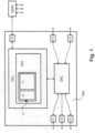
- the network forwarding apparatus SW of the embodiment of Fig. 1 that may be called a "switch”, has five input/output ports P1, P2, P3, P4, P5 for receiving and transmitting IP packets, and comprises two basic building blocks: an IP packets handling circuitry DPL, a so-called “data plane”, and an internal apparatus controller CPL, a so-called “control plane”; circuitry DPL is arranged to forward IP packets between the input/output ports P1, P2, P3, P4, P5; the internal controller CPL is arranged to control circuitry DPL.
- an IP packets handling circuitry DPL a so-called "data plane”
- an internal apparatus controller CPL a so-called "control plane”
- circuitry DPL is arranged to forward IP packets between the input/output ports P1, P2, P3, P4, P5
- the internal controller CPL is arranged to control circuitry DPL.
- Apparatus SW has also a control port PC for communication between the internal apparatus controller CPL and an external network controller NWC; external controller NWC is arranged to control not only apparatus SW, but also many other similar network apparatuses.
- Controller CPL comprises a memory MEM that is designed to store at least one state transition table TT to be used by the controller CPL for controlling the forwarding of IP packets by circuitry DPL; controller CPL is arranged to use the state transition table TT for implementing at least one finite state machine FSM and for handling separately distinct incoming IP packets flows through corresponding distinct instances of finite state machine. From the theoretical point of view, the transition table TT might be considered part of the "data plane"; in this case, the controller CPL would manage the transition table TT as an external component.
- state transition table TT corresponds to the combination of a state table ST and a flow table FT.
- Apparatus internal controller CPL is arranged to receive transition table TT through the control port PC from the network external controller NWC; in particular, it receives flow table FT with full data content and state table ST with some initial data content; during operation of apparatus SW, data content is built and partially added and partially replaced to the initial data content of state table ST.
- Fig. 2 shows the state table ST and the flow table FT;
- the state table FT comprises a key column KC and a state column SC;
- the flow table FT comprises a state column SC, an event column EC, an action column AC and an update column UC.
- Fig. 2 shows also a first key extraction function KE1 that uses first key information (corresponding to a first key extraction rule) for key extraction, and a second key extraction function KE2 that uses second key information (corresponding to a second key extraction rule) for key extraction.
- first key extraction function KE1 that uses first key information (corresponding to a first key extraction rule) for key extraction
- second key extraction function KE2 that uses second key information (corresponding to a second key extraction rule) for key extraction.
- data relating to the tables ST and FT and the functions KE1 and KE2, if used, are received from the network external controller NWC during configuration of the apparatus SW.
- Event information EI is provided by the data plane DPL to the control plane CPL for each IP packet received by the apparatus SW; typically, event information EI consists in the packet header of the received IP packet and the port number Pi of the i/o port where the IP packet has been received.
- Action information AI is provided by the control plane CPL to the data plane DPL for each IP packet received by the apparatus SW; typically, action information AI consists in the packet header of the received IP packet and the port number Pj of the i/o port where the IP packet has to be forwarded and then, typically, transmitted.
- the first key extraction function KE1 extracts key data K1 from the packet header. Key data K1 are used to query the state table ST.
- the result of the state table query is state data SD.
- State data SD and event information EI are used to query flow table.
- event information EI is used for the query, but any combination of switch port number, source MAC address, destination MAC address, source IP address, destination IP address, source TCP port, destination TCP port, and even Wireless LAN ID, IP protocol, Ethernet type.
- Matching for the purpose of querying the flow table FT is based on the state column SC (in relation to the stated data) and the event column EC (in relation to the event information).
- the result of flow table query is update information UI and action information Al.
- the second key extraction function KE2 extracts key data K2 from the packet header.
- Key data K2 and event information EI are used to update the state table ST.
- the processing shown by the flow chart of Fig. 3 refers to the element shown in Fig. 2 ; it has a start S30 and a stop S39, and comprises the following steps: S31 : receiving the flow table FT (structure and full data) at control port PC from network controller NWC (configuration of apparatus SW), S32 : receiving the state table ST (structure and some data) at control port PC from network controller NWC (configuration from apparatus SW), S33 : receiving an IP packet at a first one port Pi of the plurality of input/output ports P1, P2, P3, P4, P5, S34 : determining state data SD based on data in the IP packets by looking into the state the table ST, S35 : determining action information AI and update information UI based on information on an event corresponding to step S33 and on the state data SD determined at step S34 by looking into the flow table FT, S36 : forwarding the IP packet to no input/output ports or to at least a second one port Pj of the plurality of input/output ports
- step S33 The processing shown by the flow chart of Fig. 3 is repeated from step S33 to S38 for any new IP packets received by input/output ports P1, P2, P3, P4, P5 of apparatus SW.
- Steps S31 and S32 may be repeated in case of reconfiguration of apparatus SW by network controller NWC.
- Fig. 4 relates to the opening of a data link between nodes of a network if such opening is subject to a preliminary "port knocking" phase.
- a source node may send data to a destination node only through TCP port #22 and the preliminary "port knocking" sequence corresponds to #5123, #6234, #7345, #8456.
- the preliminary "port knocking" sequence corresponds to #5123, #6234, #7345, #8456.
- TCP destination port #5123
- TCPdport #6234
- TCPdport #7345
- TCPdport #8456
- IP packets flows are identified by the IP address of the source node.
- this example considers only the opening of a data link between nodes of a network and does not consider the subsequent closing of the data link.
- Fig. 4A The state diagram of the procedure of this example is shown in Fig. 4A ; it comprises five states labeled: "STATE-0”, “STATE-1", “STATE-2”, “STATE-3”, “STATE-4"; "STATE-0” is considered the “DEFAULT” state (the data link is closed) and “STATE-4" is considered the “OPEN” state (the data link is open).
- Fig. 4B shows a flow table FT that is used for implementing the procedure of this example according to the present invention; such flow table is stored into the control plane CPL of the apparatus SW during configuration of the apparatus SW by the network controller NWC.
- Fig. 4C shows a state table ST that is used for implementing the procedure of this example according to the present invention as it is at the beginning, i.e. just after configuration of the apparatus SW by the network controller NWC; according to this example, such state table is stored into the control plane CPL of the apparatus SW during configuration of the apparatus SW by the network controller NWC.
- an IP packet is received at an i/o port of the apparatus SW; this is an event, i.e. the first event.
- Event information EI is provided by the data plane DPL to the control plane CPL; event information EI consists in the packet header of the received IP packet and the port number Pi of the i/o port where the IP packet has been received.
- Key data K1 are extracted from the packet header based on first key information and used to query the state table ST; in this example, the first key information specifies that key data to be extracted from the header of the received IP correspond to IPsrc (i.e. "source IP address").
- the key data K1 of the currently handled IP packet is "1.10.100.1".
- the state table ST contains, for example and as shown in Fig. 4C , only the following row: KC SC * STATE-0 wherein "*" is symbol of data that match with any key data.
- the state table ST is scanned from top to bottom in order to find the first row that matches with the key data extracted from the just received IP packet.
- the result of the query i.e. state data SD, is "STATE-0" as there is only one row and as "*" matches with "1.10.100.1".
- State data SD are used to query the flow table FT.
- Event data ED are extracted from the event information EI and are used to query the flow table FT; in this example, the event data ED is the TCPdport (i.e. "TCP destination port") in the header of the received IP packet.
- TCPdport i.e. "TCP destination port
- the flow table FT is queried through the state data SD and the event data ED, i.e. it is scanned from top to bottom in order to find the first row that matches with the state data SD and the event data ED.
- the TCPdport in the currently handled IP packet is different from 5123, i.e. ED is different from 5123, a match occurs only with the last row of the flow table FT.
- the result of the query the action information AI is "drop" and the update information UI is "STATE-0".
- the received IP packet is dropped.
- the state table ST is updated.
- key data K2 are extracted from the packet header based on second key information; in this example, the second key information specifies that key data to be extracted from the header of the received IP correspond to IPsrc (i.e. "source IP address"); it is to be noted that, according to this example, the first key information and the second key information coincide and therefore the key data K1 and key data K2 are identical. In this case, the key data K2 of the currently handled IP packet is "1.10.100.1".
- TCPdport in the currently handled IP packet is equal to 5123, i.e. ED is equal to 5123, a match occurs with the first row of the flow table FT.
- the result of the query the action information AI is "drop” and the update information UI is "STATE-1".
- the received IP packet is dropped.
- the state table ST is updated.
- key data K2 are extracted from the packet header based on second key information; in this example, the second key information specifies that key data to be extracted from the header of the received IP correspond to IPsrc (i.e. "source IP address"); it is to be noted that, according to this example, the first key information and the second key information coincide and therefore the key data K1 and key data K2 are identical. In this case, the key data K2 of the currently handled IP packet is "1.10.100.1".
- the action information AI is "drop” and the update information UI is "STATE-2".
- the received IP packet is dropped.
- the state table ST is updated.
- the key data K2 are extracted from the packet header based on the second key information; in this case, the key data K2 of the currently handled IP packet is "1.10.100.1".
- the state table ST may be, for example as below.
- KC SC 1.10.100.1 STATE-2 data link from node 1.10.100.1 is on the way to be opened 1.10.100.2
- STATE-0 data link from node 1.10.100.2 is closed 1.10.200.5
- STATE-0 data link from node 1.10.200.5 is closed 1.20.500.8
- STATE-0 data link from node 1.20.500.8 is closed 1.10.100.3
- STATE-4 data link from node 1.10.100.3 is open * STATE-0
- the received IP packet is forwarded.
- the example that will described in the following with the aid of Fig. 5 relates to the forwarding of Ethernet frames by the switch SW based on MAC address of the destination node of the incoming Ethernet frames.
- the switch SW In order to carry out a good performance, the switch SW must decide, for each of the received Ethernet frames, to which of its five i/o ports P1, P2, P, P4, P5 the Ethernet frame, i.e. the handled data packet, is to be forwarded and then transmitted based on the MAC address of the destination node of the packets; therefore, according to this example, Ethernet frames flows are identified by the destination MAC address.
- the state diagram of the procedure of this example comprises six states labeled: "STATE-0”, “STATE-1”, “STATE-2”, “STATE-3”, “STATE-4", “STATE-5"; "STATE-0” is considered the “DEFAULT” state and corresponds to the state when the switch SW does not know the correct/best port for the forwarding action; "STATE-1” corresponds to the state when the correct/best port for the forwarding action is port P1; etc. ; the action “flood” means forwarding the received Ethernet frames to all the i/o ports of the switch SW.
- Fig. 5A shows a flow table FT that is used for implementing the procedure of this example according to the present invention; such flow table is stored into the control plane CPL of the apparatus SW during configuration of the apparatus SW by the network controller NWC.
- Fig. 5B shows a state table ST that is used for implementing the procedure of this example according to the present invention as it is at the beginning, i.e. just after configuration of the apparatus SW by the network controller NWC; according to this example, such state table is stored into the control plane CPL of the apparatus SW during configuration of the apparatus SW by the network controller NWC.
- the table of Fig. 5B means that the switch SW has no knowledge of the population and topology of the network.
- an IP packet is received at an i/o port of the apparatus SW; this is an event, i.e. the first event.
- Event information EI is provided by the data plane DPL to the control plane CPL; event information EI consists in the packet header of the received Ethernet frame and the port number Pi of the i/o port where the Ethernet frame has been received.
- Key data K1 are extracted from the packet header based on first key information and used to query the state table ST; in this example, the first key information specifies that key data to be extracted from the header of the received Ethernet frame correspond to MACdst (i.e. "destination MAC address").
- the key data K1 of the currently handled Ethernet frame is Address_003.
- the state table ST contains, for example and as shown in Fig. 5B , only the following row: KC SC * STATE-0 wherein "*" is symbol of data that match with any key data.
- the state table ST is scanned from top to bottom in order to find the first row that matches with the key data extracted from the just received IP packet.
- the result of the query i.e. state data SD, is "STATE-0" as there is only one row and as "*" matches with Address_1.
- State data SD are used to query the flow table FT.
- Event data ED are extracted from the event information EI and are used to query the flow table FT; in this example, the event data ED is the port # where the currently handled Ethernet frame has been received, for example port P2.
- the flow table FT is queried through the state data SD and the event data ED, i.e. it is scanned from top to bottom in order to find the first row that matches with the state data SD and the event data ED.
- the action information AI is "flood" and the update information UI is "STATE-2".
- the received Ethernet frame is flooded, i.e. forwarded to all the i/o ports of the switch SW.
- the state table ST is updated.
- key data K2 are extracted from the packet header based on second key information; in this example, the second key information specifies that key data to be extracted from the header of the received Ethernet frame correspond to MACsrc (i.e. "source MAC address"); it is to be noted that, according to this example, the first key information is different from the second key information coincide. In this case, the key data K2 of the currently handled Ethernet frame is Address_008.
- Key data K1 are extracted from the packet header based on first key information.
- the extracted key data K1 is Address_008.
- the state table ST is queried. i.e. the state table ST is scanned from top to bottom in order to find the first row that matches with the key data extracted from the just received Ethernet frame.
- State data SD are used to query the flow table FT.
- Event data ED are extracted from the event information EI; in this case, the event data ED is port P3.
- the flow table FT is queried through the state data SD and the event data ED, i.e. it is scanned from top to bottom in order to find the first row that matches with the state data SD and the event data ED.
- the action information AI is "forward(P2)" and the update information UI is "STATE-3".
- the received Ethernet frame is forwarded to port P2 of the switch SW.
- the state table ST is updated.
- key data K2 are extracted from the packet header based on second key information; in this example, the second key information specifies that key data to be extracted from the header of the received Ethernet frame correspond to MACsrc (i.e. "source MAC address"). In this case, the key data K2 of the currently handled IP packet is Address_005.
- KC SC Address_005 STATE-3 node with MAC address Address_005 may be reached from port P3 Address_008 STATE-2 node with MAC address Address_008 may be reached from port P2 * STATE-0
- the dependence between the handling of Ethernet frames flows is due to the relation between the instances of finite state machine; in fact, an instance of finite state machine causes changes in other instances of finite state machine, in particular updates in the rows of the state table ST relating to other instances of finite state machine.
- tables ST and FT are scanned from top to bottom in order to find a match; anyway, it is to be understood that the matching priority may be determined in different ways (see for example OpenFlow).
Landscapes
- Engineering & Computer Science (AREA)
- Computer Networks & Wireless Communication (AREA)
- Signal Processing (AREA)
- Data Exchanges In Wide-Area Networks (AREA)
Description
- The present invention relates to an apparatus for handling data packets (for example IP packets, Ethernet packets, Ethernet frames, ...).
- In particular, the present invention is advantageously applied in those network switching apparatuses generally called "switches" and concentrates on how to forward data packets between the their input/output ports. Nowadays, the word "switch" may refer to an apparatus operating at
Layer 2 orLayer 3 orLayer 4 of the OSI model; in the past, the word "switch" was limited to an apparatus operating atLayer 2 and the word "router" was limited to an apparatus operating atLayer 3. - Just a few years ago it was normal to configure network apparatuses using proprietary interfaces, differing across vendors, apparatus types (switches, routers, firewalls, load balancers, etc.), and even different firmware releases for a same apparatus. Managing heterogeneous multivendor networks of non-marginal scale was (and still is) extremely difficult, and required (and still requires) a huge expertise.
- "OpenFlow" emerged very recently, i.e. in 2008, as an attempt to change this situation. OpenFlow's breakthrough was the identification of a vendor-agnostic programming abstraction for configuring the forwarding behavior of network switching apparatus. Via the OpenFlow Application Programming Interface, in short "API", network administrators can remotely reconfigure at runtime forwarding tables, probe for flow statistics, and redirect packets not matching any local flow entry towards a network controller for further analysis/processing and for taking relevant decisions; in essence "program" the network from a central control point, clearly separated from the forwarding level.
- Today, such vision is called Software Defined Networking, in short "SDN". OpenFlow turned to be immediately deployable, thanks to its pragmatic balance between open network programmability and real world vendors' and deployers' needs. Starting from the recognition that several different network devices implement somewhat similar flow tables for a broad range of networking functionalities (L2/L3 forwarding, firewall, NAT, etc.), the authors of Open Flow proposed an abstract model of a programmable flow table which was amenable to high-performance and low-cost implementations; capable of supporting a broad range of research; and consistent with vendors' need for closed platforms.
- Via the Open Flow "match/action" abstraction, the device programmer can broadly specify a flow via an header matching rule, associate forwarding/processing actions to the matching packets, and access bytes/packet statistics associated to the specified flow.
- Almost six years have now passed since the Open Flow inception, and the latest Open Flow standard, now at version 1.4, appears way more complex than the initial elegant and simple concept. To fit the real world needs, a huge number of extension (not only the initially foreseen functional ones, such as supplementary actions or more flexible header matching, but also structural ones such as action bundles, multiple pipelined tables, synchronized tables, and many more) were promoted in the course of the standardization process. And new extensions are currently under discussion for the next OpenFlow version.
- All this hectic work was not accompanied by any substantial rethinking in the original programmatic abstraction (besides the abandoned Google OpenFlow 2.0 proposal, considered too ambitious and futuristic), so as to properly capture the emerging extensions, simplify their handling, and prevent the emergence of brittle, platform-specific, implementations which may ultimately threaten the original vendor-independency goal of the OpenFlow inventors.
- Even if an OpenFlow apparatus may now be rich of functionalities and primitives, it remains completely "dumb", with all the "smartness" placed at the central network controller side.
- From the article "Simpler Network Configurationwith State-based Network Policies" by H. Kim et al. of the Georgia Institute of Technlogy, College of Computing SCS technical report, there is know a solution based on OpenFlow; according to this solution, the network forwarding apparatuses (see switches in
Figure 1 ) are traditional Open Flow switches, i.e. "dumb", and all the "smartness" is placed inside a central network controller called "PyResonance controller" (see upper part ofFigure 1 and corresponding explanation in paragraph 2.1). The network forwarding apparatuses (that may be called simply "apparatuses") according to this solution comprises, as always, an internal data packets handling circuitry and an internal apparatus controller. The "smartness" is implemented inside the central network controller using a programming abstraction based on traditional Finite State Machines, in short "FSM". - Recently and despite OpenFlow's data plane programmability, the need to use advanced packet handling for important network services has lead to the proliferation of many types of specialized "middle-boxes". The extension of programmability and exibility features to these advanced network functions is a crucial aspect, and a recent trend is that of virtualizing them in data centers on general purpose hardware platforms and to make them programmable and configurable using SDN approaches.
- The present Inventors wanted to follow the OpenFlow approach (avoiding "middle-boxes" and "virtualization"), i.e. network management control should be (logically) centralized; in other words, they wanted to keep the control plane and the data plane separate according to the spirit of SDN.
- However the present Inventors posit that several statefull tasks, just involving local states inside single links/switches are unnecessarily centralized according to OpenFlow and not deployed to the local apparatuses. As a result, the explicit involvement of the controller for any statefull processing and for any update of the match/action rules, is problematic. In the best case, this leads to extra signaling load and processing delay, and calls for a capillary distributed implementation of the "logically" centralized controller. In the worst case, the very slow control plane operation a priori prevents the support of network control algorithms which require prompt, real time, reconfiguration in the data plane forwarding behavior.
- In essence, dumbness in the data forwarding plane appears to be a by-product of the limited capability of the OpenFlow data plane API - Application Programming Interface, rather than an actual design choice or an SDN postulate.
- Therefore, the present Inventors thought of a better data plane API - Application Programming Interface which would permit to program some level of smartness directly inside the forwarding apparatuses.
- The present Inventors thought that a major shortcoming of OpenFlow is its inability to permit the programmer to deploy states inside the forwarding apparatus.
- However, adding states to OpenFlow was considered not sufficient: the programmer should be entitled to formally specify how states should be handled, and this specification should be executed inside the apparatus with no further interaction with the controller.
- Furthermore, they considered that an effective solution should have come along with two attributes: (1) be amenable to high speed implementation, (2) not violate the vendor-agnostic principle which has driven the OpenFlow invention, and which has fostered SDN; in essence, an effective solution should be a concrete and pragmatic "abstraction", rather than a theoretical approach.
- The present inventors proposes of a viable abstraction to formally describe a desired statefull processing of flows inside the network forwarding apparatus, without requiring the apparatus to be open source or to expose its internal design. Such abstraction relies on Finite State Machines, in short "FSM", in particular eXtended Finite State Machines, in short "XFSM".
- Extending the OpenFlow abstraction through the use of FSM, in particular XFSM, allows to offload on high performance switches a pretty large set of functions reducing the need to rely on controllers and middle-boxes.
- According to the present invention, inclusion of flow states is not limited to the functionality of the apparatus, i.e. its packets handling capabilities, but it takes into account the API - Application Programming Interface.
- Advantageously, extending the OpenFlow abstraction through the use of FSM is not disruptive, i.e. it is in line with traditional OpenFlow, and therefore it would be relatively easy to be introduced into existing networks and used by current network operators.
- The present Inventors are aware that XFSMs have already been proposed in the field of network apparatuses; anyway, this was done for a completely different application, i.e. in order to convey a desired medium access control operation into a wireless interface card; therefore, the old application and the new application are not related and comparable.
- From document
US2009/303990A1 it is known a network switch ASIC with off-chip interface for external routing logic. According to this solution, there 30 are both an internal routing logic and an external routing logic being independent between each other. independent between each other. -
US 2006/221930 A1 discusses distributing packets across available output paths within a network. A distribution key is extracted from each packet and is hashed to generate a hash value. An output path for each packet is selected by using all N bits of the hash value to query a distribution table having at least 2 indications of the output paths available for that packet. - The present invention is defined by the appended claims.
- The present invention relates more specifically to a (network forwarding) apparatus having a plurality of input/output ports for receiving and transmitting data packets, and comprising a data packets handling circuitry arranged to forward data packets between the input/output ports and an internal apparatus controller arranged to control said data packet handling circuitry; the apparatus has a control port for communication between the internal apparatus controller and an external network controller, and includes the features set out in appended
claim 1. - The data packets may be for example IP packets, Ethernet packets, Ethernet frames, ... ; it is not to be excluded that such apparatus would be arranged to handle different kinds of data packets.
- The apparatus may operate at
Layer 2 orLayer 3 orLayer 4 of the OSI model; it is not to be excluded that such apparatus would be arranged to operate different layers. - The control port is a port dedicated to the communication with the external network controller or may be any of the input/output ports; in the second case, control information from/to the external network controller are transported, at least partially, by the network transporting data packets.
- It is possible that the apparatus stores multiple tables for implementing multiple (different) finite state machines in order to carry out multiple (different) handling strategies in parallel and/or in series - particularly in this case, it is likely that the apparatus comprises internal queues for storing data packets between a handling strategy and the following handling strategy and that data packets are forwarded from an input/output port to and internal queue or from one internal queue to another internal queue or from one internal queue to an input/output port. This possibility, is not to be confused with multiple instances of the same finite state machine. In fact, in general, a network forwarding apparatus has to handle a plurality of incoming data packets flows according to the same strategy and each flow may be in a different state; this is implemented "conceptually" through a plurality of instances of the same finite state machine.
- In the above-defined solution, the architecture of the apparatus controller is not specified; it is only important that it is able to receive a table from the external network controller and interpret it as a state transition table of a finite state machine; this means that the above-defined solution is hardware independent. Receiving a table may mean: receiving the definition of the table structure and its data content, or receiving only its data content and the table structure is already known to both the external controller and the internal controller.
- It is to be noted that, even if such apparatus is able to carry out statefull processing of data packets flows, it is also able to carry out stateless processing of data packets flows (for example simple routing through a routing table); in fact, a stateless processing may be considered a statefull processing based on only one state.
- According to a claimed advantageous aspect, at least one state transition table used by the apparatus corresponds to the combination of a state table and a flow table, the apparatus controller is arranged to store the state table and the flow table, the apparatus controller is arranged to receive the flow table through the control port, and optionally the apparatus controller is arranged to receive the state table through the control port.
- According to a not claimed advantageous aspect, the heart of the finite state machine is the flow table and needs to be received from the external controller before the apparatus starts handling data packets accordingly. Depending on the implementation of this embodiment, the data content of the state table may be completely built by the internal controller or, alternatively, some data content may be received from the external controller before the apparatus starts handling data packets according to the corresponding flow table. It is important to consider that the structure of the state table and the structure of the flow table are linked to each other as they constitute a state transition table.
- According to another claimed advantageous aspect, the state table comprises a key column and a state column, and the apparatus controller is arranged to determine through the state table state data based on data in incoming data packets, and the flow table comprises a state column, an event column, an action column and an update column, and the apparatus controller is arranged to determine through the flow table action information and update information based on information on events occurring at the input/output ports and on state data determined through the state table, the action information relating to forwarding actions to be performed on incoming data packets, the update information relating to row updates to be performed on data in the state table.
- The typical forwarding actions are: drop a data packet, flood a data packet to all the ports of the apparatus (this is done for example in case of broadcast traffic or in case that the correct forwarding path is not known to the apparatus) and forward the data packet to one port of the apparatus (this is done for example in case of unicast traffic) or more ports (this is done for example in case of multicast traffic) of the apparatus; other actions are not to be excluded for example those already typical in Open Flow and Open Flow apparatuses such as "header-rewrite", "rate-limit", ....
- Updating the state table during operation of the apparatus means updating the current state of the finite state machine, precisely the current state of an instance of the finite state machine.
- It is to be noted that, in general, each cell of the tables, in particular each cell of the flow, table, may store one or more piece of information; this is particularly true for the action information and the update information; in fact, one or more forwarding actions may be provided and/or one or more updating actions may be provided. It may be possible that the forwarding actions and/or the updating actions be subject to conditions specified in the cells of the flow table.
- According to a preferred claimed embodiment, the apparatus controller is arranged to use at least one state transition table for handling separately distinct incoming data packets flows through corresponding distinct instances of finite state machine, and the apparatus controller is arranged to handle distinct incoming data packets flows independently or dependently from each other through relations between instances of finite state machine.
- According to a not claimed preferred embodiment, an event and packet relating to a first incoming data packets flow may trigger a state transition in the instance of finite state machine relating to the first flow or in the instance of finite state machine relating to a second flow; it is also possible that an event and packet may trigger multiple state transitions. This means that there may be a relation between instances of finite state machines.
- According to claimed preferred embodiment, update information relates to the same instance of finite state machine or to a different instance of finite state machine. This is a way to implement the above-mentioned relation.
- According to a claimed preferred embodiment, the apparatus controller is arranged to implement at least one key extraction function.
- According to a claimed preferred embodiment, the apparatus controller is arranged to apply a first key extraction function to data in incoming data packets for the purpose of querying the state table.
- According to a claimed preferred embodiment, the apparatus controller is arranged to apply a second key extraction function to data in incoming data packets for the purpose of updating the state table.
- According to a claimed preferred embodiment, the apparatus controller is arranged to receive one or two key extraction rules through the control port to be used for the key extraction function or functions.
- The optional features of the invention relating to key extraction will be clearer from the detailed description.
- A method of handling data packets in an apparatus having a plurality of input/output ports for receiving and transmitting data packets is also disclosed herein.
- The present invention will be described in the following with the aid of annexed drawings wherein:
-
Fig. 1 shows a simplified block diagram of an embodiment of an apparatus according to the present invention, -
Fig. 2 shows schematically the use of a state table and a flow table according to a method implemented by an apparatus according to the present invention, -
Fig. 3 shows a flow chart of an embodiment of a method implemented by an apparatus according to the present invention, -
Fig. 4 shows a state diagram and two tables relating to a first example of application and -
Fig. 5 shows two tables relating to a second example of application. - Such description and such drawings are not to be considered as limiting the present invention that is only defined by the annexed claims; in fact, it will clear to one skilled in the art that the embodiments described in the following may be subject to modifications and variants in their details, albeit within the scope of the invention as defiend by the appended set of claims.
- The network forwarding apparatus SW of the embodiment of
Fig. 1 , that may be called a "switch", has five input/output ports P1, P2, P3, P4, P5 for receiving and transmitting IP packets, and comprises two basic building blocks: an IP packets handling circuitry DPL, a so-called "data plane", and an internal apparatus controller CPL, a so-called "control plane"; circuitry DPL is arranged to forward IP packets between the input/output ports P1, P2, P3, P4, P5; the internal controller CPL is arranged to control circuitry DPL. Apparatus SW has also a control port PC for communication between the internal apparatus controller CPL and an external network controller NWC; external controller NWC is arranged to control not only apparatus SW, but also many other similar network apparatuses. Controller CPL comprises a memory MEM that is designed to store at least one state transition table TT to be used by the controller CPL for controlling the forwarding of IP packets by circuitry DPL; controller CPL is arranged to use the state transition table TT for implementing at least one finite state machine FSM and for handling separately distinct incoming IP packets flows through corresponding distinct instances of finite state machine. From the theoretical point of view, the transition table TT might be considered part of the "data plane"; in this case, the controller CPL would manage the transition table TT as an external component. - In the embodiment of
Fig. 1 , state transition table TT corresponds to the combination of a state table ST and a flow table FT. Apparatus internal controller CPL is arranged to receive transition table TT through the control port PC from the network external controller NWC; in particular, it receives flow table FT with full data content and state table ST with some initial data content; during operation of apparatus SW, data content is built and partially added and partially replaced to the initial data content of state table ST. -
Fig. 2 shows the state table ST and the flow table FT; the state table FT comprises a key column KC and a state column SC; the flow table FT comprises a state column SC, an event column EC, an action column AC and an update column UC. -
Fig. 2 shows also a first key extraction function KE1 that uses first key information (corresponding to a first key extraction rule) for key extraction, and a second key extraction function KE2 that uses second key information (corresponding to a second key extraction rule) for key extraction. - In general, data relating to the tables ST and FT and the functions KE1 and KE2, if used, are received from the network external controller NWC during configuration of the apparatus SW.
- Event information EI is provided by the data plane DPL to the control plane CPL for each IP packet received by the apparatus SW; typically, event information EI consists in the packet header of the received IP packet and the port number Pi of the i/o port where the IP packet has been received.
- Action information AI is provided by the control plane CPL to the data plane DPL for each IP packet received by the apparatus SW; typically, action information AI consists in the packet header of the received IP packet and the port number Pj of the i/o port where the IP packet has to be forwarded and then, typically, transmitted.
- The first key extraction function KE1 extracts key data K1 from the packet header. Key data K1 are used to query the state table ST.
- The result of the state table query is state data SD.
- State data SD and event information EI (the port number Pi, or selected data in the packet header, or port number Pi and selected data in the packet header) are used to query flow table. Usually, not the whole event information EI is used for the query, but any combination of switch port number, source MAC address, destination MAC address, source IP address, destination IP address, source TCP port, destination TCP port, and even Wireless LAN ID, IP protocol, Ethernet type. Matching for the purpose of querying the flow table FT is based on the state column SC (in relation to the stated data) and the event column EC (in relation to the event information).
- The result of flow table query is update information UI and action information Al. The second key extraction function KE2 extracts key data K2 from the packet header.
- Key data K2 and event information EI are used to update the state table ST.
- The processing shown by the flow chart of
Fig. 3 refers to the element shown inFig. 2 ; it has a start S30 and a stop S39, and comprises the following steps:S31 : receiving the flow table FT (structure and full data) at control port PC from network controller NWC (configuration of apparatus SW), S32 : receiving the state table ST (structure and some data) at control port PC from network controller NWC (configuration from apparatus SW), S33 : receiving an IP packet at a first one port Pi of the plurality of input/output ports P1, P2, P3, P4, P5, S34 : determining state data SD based on data in the IP packets by looking into the state the table ST, S35 : determining action information AI and update information UI based on information on an event corresponding to step S33 and on the state data SD determined at step S34 by looking into the flow table FT, S36 : forwarding the IP packet to no input/output ports or to at least a second one port Pj of the plurality of input/output ports P1, P2, P3, P4, P5 according to the action information AI determined at step S35, S37 : updating the state table ST according to the update information UI determined at step S35, S38 : transmitting the IP packet in accordance to the result of step S36. - The processing shown by the flow chart of
Fig. 3 is repeated from step S33 to S38 for any new IP packets received by input/output ports P1, P2, P3, P4, P5 of apparatus SW. - Steps S31 and S32 may be repeated in case of reconfiguration of apparatus SW by network controller NWC.
- The example that will described in the following with the aid of
Fig. 4 relates to the opening of a data link between nodes of a network if such opening is subject to a preliminary "port knocking" phase. - According to this example, a source node may send data to a destination node only through
TCP port # 22 and the preliminary "port knocking" sequence corresponds to #5123, #6234, #7345, #8456. In other words, if a first node wants to send data packets to another node, at first the first node must send an IP packet wherein TCPdport (i.e. "TCP destination port") = #5123, then the first node must send an IP packet wherein TCPdport = #6234, then the first node must send an IP packet wherein TCPdport = #7345, finally the first node must send an IP packet wherein TCPdport = #8456; afterwards, the first node may send IP packets carrying data to another node but specifying TCPdport = #22. - Therefore, according to this example, IP packets flows are identified by the IP address of the source node.
- For the sake of simplicity, this example considers only the opening of a data link between nodes of a network and does not consider the subsequent closing of the data link.
- The state diagram of the procedure of this example is shown in
Fig. 4A ; it comprises five states labeled: "STATE-0", "STATE-1", "STATE-2", "STATE-3", "STATE-4"; "STATE-0" is considered the "DEFAULT" state (the data link is closed) and "STATE-4" is considered the "OPEN" state (the data link is open). -
Fig. 4B shows a flow table FT that is used for implementing the procedure of this example according to the present invention; such flow table is stored into the control plane CPL of the apparatus SW during configuration of the apparatus SW by the network controller NWC. -
Fig. 4C shows a state table ST that is used for implementing the procedure of this example according to the present invention as it is at the beginning, i.e. just after configuration of the apparatus SW by the network controller NWC; according to this example, such state table is stored into the control plane CPL of the apparatus SW during configuration of the apparatus SW by the network controller NWC. - At the beginning, an IP packet is received at an i/o port of the apparatus SW; this is an event, i.e. the first event.
- Event information EI is provided by the data plane DPL to the control plane CPL; event information EI consists in the packet header of the received IP packet and the port number Pi of the i/o port where the IP packet has been received.
- The activities described in the following occur within the control plane CPL.
- Key data K1 are extracted from the packet header based on first key information and used to query the state table ST; in this example, the first key information specifies that key data to be extracted from the header of the received IP correspond to IPsrc (i.e. "source IP address").
- For example, the key data K1 of the currently handled IP packet is "1.10.100.1". At the beginning, the state table ST contains, for example and as shown in
Fig. 4C , only the following row:KC SC * STATE-0 - The state table ST is scanned from top to bottom in order to find the first row that matches with the key data extracted from the just received IP packet. The result of the query, i.e. state data SD, is "STATE-0" as there is only one row and as "*" matches with "1.10.100.1".
- State data SD are used to query the flow table FT.
- Event data ED are extracted from the event information EI and are used to query the flow table FT; in this example, the event data ED is the TCPdport (i.e. "TCP destination port") in the header of the received IP packet.
- Thus the flow table FT is queried through the state data SD and the event data ED, i.e. it is scanned from top to bottom in order to find the first row that matches with the state data SD and the event data ED.
- At this point, data SD="STATE-0".
- If the TCPdport in the currently handled IP packet is different from 5123, i.e. ED is different from 5123, a match occurs only with the last row of the flow table FT. The result of the query, the action information AI is "drop" and the update information UI is "STATE-0".
- Based on the action information AI (that is provided by the control plane CPL to the data plane DPL), the received IP packet is dropped.
- Based on the update information UI the state table ST is updated.
- In order to carry out the updating, key data K2 are extracted from the packet header based on second key information; in this example, the second key information specifies that key data to be extracted from the header of the received IP correspond to IPsrc (i.e. "source IP address"); it is to be noted that, according to this example, the first key information and the second key information coincide and therefore the key data K1 and key data K2 are identical. In this case, the key data K2 of the currently handled IP packet is "1.10.100.1".
- At this stage a row is added to the state table ST using key data K2, i.e. "1.10.100.1", and update information UI, "STATE-0", see below.
KC SC 1.10.100.1 STATE-0 * STATE-0 - If the TCPdport in the currently handled IP packet is equal to 5123, i.e. ED is equal to 5123, a match occurs with the first row of the flow table FT. The result of the query, the action information AI is "drop" and the update information UI is "STATE-1".
- Based on the action information AI (that is provided by the control plane CPL to the data plane DPL), the received IP packet is dropped.
- Based on the update information UI the state table ST is updated.
- In order to carry out the updating, key data K2 are extracted from the packet header based on second key information; in this example, the second key information specifies that key data to be extracted from the header of the received IP correspond to IPsrc (i.e. "source IP address"); it is to be noted that, according to this example, the first key information and the second key information coincide and therefore the key data K1 and key data K2 are identical. In this case, the key data K2 of the currently handled IP packet is "1.10.100.1".
- At this stage a row is added to the state table ST using key data K2, i.e. "1.10.100.1", and update information UI, "STATE-1", see below.
KC SC 1.10.100.1 STATE-1 * STATE-0 - Considering now a further IP packet received, for example, from node "1.10.100.1" and wherein the TCPdport is equal to 6234.
- ED is equal to 6234 and a match occurs with the second row of the flow table FT. The result of the query, the action information AI is "drop" and the update information UI is "STATE-2".
- Based on the action information AI (that is provided by the control plane CPL to the data plane DPL), the received IP packet is dropped.
- Based on the update information UI the state table ST is updated.
- In order to carry out the updating, the key data K2 are extracted from the packet header based on the second key information; in this case, the key data K2 of the currently handled IP packet is "1.10.100.1".
- At this stage a row is updated to the state table ST using key data K2, i.e. "1.10.100.1", and update information UI, "STATE-2", see below, as there is already a row in state table ST wherein the key data in the key column KC is equal to the key data extracted from the handled IP packet.
KC SC 1.10.100.1 STATE-2 * STATE-0 - At this point other received IP packets are handled in the same way as described above.
- After handling a certain number of received IP packets, the state table ST may be, for example as below.
KC SC 1.10.100.1 STATE-2 data link from node 1.10.100.1 is on the way to be opened 1.10.100.2 STATE-0 data link from node 1.10.100.2 is closed 1.10.200.5 STATE-0 data link from node 1.10.200.5 is closed 1.20.500.8 STATE-0 data link from node 1.20.500.8 is closed 1.10.100.3 STATE-4 data link from node 1.10.100.3 is open * STATE-0 - Till now, five IP packets flows have been handled with: one from node 1.10.100.1, one from node 1.10.100.2, one from node 1.10.100.3, one from node 1.10.200.5, and one from node 1.20.500.8.
- It is apparent that each IP packets flow is dealt with independently. In practice, through the combination of the state table ST and the flow table FT a plurality of distinct instances of finite state machine is implemented; in particular, the heart of the finite state machine is the flow table while the state table allows to have a plurality of instances.
- Considering now a further IP packet received, for example, from node "1.10.100.3".
- If the TCPdport in this IP packet is equal to 22, i.e. ED is equal to 22, a match occurs with the fifth row of the flow table FT. The result of the query, the action information AI is "toward" and the update information UI is "STATE-4".
- Based on the action information AI (that is provided by the control plane CPL to the data plane DPL), the received IP packet is forwarded.
- Based on the update information UI the state table ST should be updated. Anyway, there is already a row wherein the key is "1.10.100.3" and the state is "STATE-4"; therefore, there is nothing to add or update.
- The handling of further IP packets follow in the same way as described above. According to the above description, tables ST and FT are scanned from top to bottom in order to find a match; anyway, it is to be understood that the matching priority may be determined in different ways (see for example Open Flow).
- The example that will described in the following with the aid of
Fig. 5 relates to the forwarding of Ethernet frames by the switch SW based on MAC address of the destination node of the incoming Ethernet frames. - In order to carry out a good performance, the switch SW must decide, for each of the received Ethernet frames, to which of its five i/o ports P1, P2, P, P4, P5 the Ethernet frame, i.e. the handled data packet, is to be forwarded and then transmitted based on the MAC address of the destination node of the packets; therefore, according to this example, Ethernet frames flows are identified by the destination MAC address.
- The state diagram of the procedure of this example comprises six states labeled: "STATE-0", "STATE-1", "STATE-2", "STATE-3", "STATE-4", "STATE-5"; "STATE-0" is considered the "DEFAULT" state and corresponds to the state when the switch SW does not know the correct/best port for the forwarding action; "STATE-1" corresponds to the state when the correct/best port for the forwarding action is port P1; etc. ; the action "flood" means forwarding the received Ethernet frames to all the i/o ports of the switch SW.
-
Fig. 5A shows a flow table FT that is used for implementing the procedure of this example according to the present invention; such flow table is stored into the control plane CPL of the apparatus SW during configuration of the apparatus SW by the network controller NWC. -
Fig. 5B shows a state table ST that is used for implementing the procedure of this example according to the present invention as it is at the beginning, i.e. just after configuration of the apparatus SW by the network controller NWC; according to this example, such state table is stored into the control plane CPL of the apparatus SW during configuration of the apparatus SW by the network controller NWC. The table ofFig. 5B means that the switch SW has no knowledge of the population and topology of the network. - At the beginning, an IP packet is received at an i/o port of the apparatus SW; this is an event, i.e. the first event.
- Event information EI is provided by the data plane DPL to the control plane CPL; event information EI consists in the packet header of the received Ethernet frame and the port number Pi of the i/o port where the Ethernet frame has been received.
- The activities described in the following occur within the control plane CPL.
- Key data K1 are extracted from the packet header based on first key information and used to query the state table ST; in this example, the first key information specifies that key data to be extracted from the header of the received Ethernet frame correspond to MACdst (i.e. "destination MAC address").
- For example, the key data K1 of the currently handled Ethernet frame is Address_003.
- At the beginning, the state table ST contains, for example and as shown in
Fig. 5B , only the following row:KC SC * STATE-0 - The state table ST is scanned from top to bottom in order to find the first row that matches with the key data extracted from the just received IP packet. The result of the query, i.e. state data SD, is "STATE-0" as there is only one row and as "*" matches with Address_1.
- State data SD are used to query the flow table FT.
- Event data ED are extracted from the event information EI and are used to query the flow table FT; in this example, the event data ED is the port # where the currently handled Ethernet frame has been received, for example port P2.
- Thus the flow table FT is queried through the state data SD and the event data ED, i.e. it is scanned from top to bottom in order to find the first row that matches with the state data SD and the event data ED.
- A match occurs with the seventh row of the flow table FT.
- The result of the query, the action information AI is "flood" and the update information UI is "STATE-2".
- Based on the action information AI (that is provided by the control plane CPL to the data plane DPL), the received Ethernet frame is flooded, i.e. forwarded to all the i/o ports of the switch SW.
- Based on the update information UI the state table ST is updated.
- In order to carry out the updating, key data K2 are extracted from the packet header based on second key information; in this example, the second key information specifies that key data to be extracted from the header of the received Ethernet frame correspond to MACsrc (i.e. "source MAC address"); it is to be noted that, according to this example, the first key information is different from the second key information coincide. In this case, the key data K2 of the currently handled Ethernet frame is Address_008.
- At this stage a row is added to the state table ST using key data K2, i.e. Address_008, and update information UI, "STATE-2", see below.
KC SC Address_008 STATE-2 * STATE-0 - We assume now that an IP packet is received at port P3 coming from a node having MAC address equal to Address_005 and directed to a node having MAC address equal to Address_008.
- Key data K1 are extracted from the packet header based on first key information. The extracted key data K1 is Address_008.
- The state table ST is queried. i.e. the state table ST is scanned from top to bottom in order to find the first row that matches with the key data extracted from the just received Ethernet frame.
- The result of the query, i.e. state data SD, is "STATE-2".
- State data SD are used to query the flow table FT.
- Event data ED are extracted from the event information EI; in this case, the event data ED is port P3.
- Thus the flow table FT is queried through the state data SD and the event data ED, i.e. it is scanned from top to bottom in order to find the first row that matches with the state data SD and the event data ED.
- The result of the query, the action information AI is "forward(P2)" and the update information UI is "STATE-3".
- Based on the action information AI (that is provided by the control plane CPL to the data plane DPL), the received Ethernet frame is forwarded to port P2 of the switch SW.
- Based on the update information UI the state table ST is updated.
- In order to carry out the updating, key data K2 are extracted from the packet header based on second key information; in this example, the second key information specifies that key data to be extracted from the header of the received Ethernet frame correspond to MACsrc (i.e. "source MAC address"). In this case, the key data K2 of the currently handled IP packet is Address_005.
- At this stage a row is added to the state table ST using key data K2, i.e. Address_005, and update information UI, "STATE-3", see below.
KC SC Address_005 STATE-3 node with MAC address Address_005 may be reached from port P3 Address_008 STATE-2 node with MAC address Address_008 may be reached from port P2 * STATE-0 - The handling of further Ethernet frames follow in the same way as described above.
- Till now, two IP packets flows have been handled with: one from node with MAC address Address_005, and one from node with MAC address Address_008.
- It is apparent that each Ethernet frames flow is dealt with dependently due to the "MAC learning function". In practice, through the combination of the state table ST and the flow table FT a plurality of distinct instances of finite state machine is implemented; in particular, the heart of the finite state machine is the flow table while the state table allows to have a plurality of instances.
- The dependence between the handling of Ethernet frames flows is due to the relation between the instances of finite state machine; in fact, an instance of finite state machine causes changes in other instances of finite state machine, in particular updates in the rows of the state table ST relating to other instances of finite state machine.
- According to the above description, tables ST and FT are scanned from top to bottom in order to find a match; anyway, it is to be understood that the matching priority may be determined in different ways (see for example OpenFlow).
Claims (7)
- An apparatus having a plurality of input/output ports for receiving and transmitting data packets, and comprising:- a data packets handling circuitry arranged to forward data packets between the input/output ports, and- an internal apparatus controller arranged to control said data packet handling circuitry, the apparatus having a control port for communication between the internal apparatus controller and an external network controller,wherein the internal apparatus controller is further arranged to:- store at least one state transition table to be used for controlling the forwarding of data packets by the data packets handling circuitry,- use said at least one state transition table for implementing at least one finite state machine,- use said at least one state transition table for handling separately distinct incoming data packets flows through corresponding distinct instances of the at least one finite state machine,- receive said at least one state transition table through the control port,wherein said at least one state transition table corresponds to the combination of a state table and a flow table,wherein the state table comprises a key column and a state column, and the internal apparatus controller is further arranged to determine through the state table state data based on data in incoming data packets,
andwherein the flow table comprises a state column, an event column, an action column and an update column, and the internal apparatus controller is further arranged to determine through the flow table action information and update information based on information on events occurring at the input/output ports and on the state data determined through the state table, the action information relating to forwarding actions to be performed on the incoming data packets and the update information relating to row updates to be performed on the state data in the state table. - The apparatus according to claim 1,
wherein the internal apparatus controller is arranged to handle distinct incoming data packets flows independently or dependently from each other through relations between instances of finite state machine. - The apparatus according to claim 2,
wherein the update information relates to a same instance of finite state machine or to a different instance of finite state machine. - The apparatus according to any of the preceding claims,
wherein the internal apparatus controller is further arranged to implement at least one key extraction function. - The apparatus according to claim 4,
wherein the internal apparatus controller is further arranged to apply a first key extraction function to the data in the incoming data packets for the purpose of querying the state table. - The apparatus according to claim 4 or 5,
wherein the internal apparatus controller is further arranged to apply a second key extraction function to data in incoming data packets for the purpose of updating the state table. - The apparatus according to claim 4 or 5 or 6,
wherein the internal apparatus controller is further arranged to receive one or two key extraction rules through the control port to be used for the key extraction function or functions.
Applications Claiming Priority (2)
| Application Number | Priority Date | Filing Date | Title |
|---|---|---|---|
| ITCO20140005 | 2014-03-12 | ||
| PCT/IB2015/051725 WO2015136432A1 (en) | 2014-03-12 | 2015-03-10 | Method of handling data packets through a state transition table and apparatus using the same |
Publications (2)
| Publication Number | Publication Date |
|---|---|
| EP3117572A1 EP3117572A1 (en) | 2017-01-18 |
| EP3117572B1 true EP3117572B1 (en) | 2023-03-29 |
Family
ID=50733141
Family Applications (1)
| Application Number | Title | Priority Date | Filing Date |
|---|---|---|---|
| EP15714646.5A Active EP3117572B1 (en) | 2014-03-12 | 2015-03-10 | Method of handling data packets through a state transition table and apparatus using the same |
Country Status (3)
| Country | Link |
|---|---|
| US (1) | US10110489B2 (en) |
| EP (1) | EP3117572B1 (en) |
| WO (1) | WO2015136432A1 (en) |
Families Citing this family (7)
| Publication number | Priority date | Publication date | Assignee | Title |
|---|---|---|---|---|
| EP3369225B1 (en) * | 2016-03-31 | 2020-09-30 | NEC Corporation | Software-enhanced stateful switching architecture |
| ITUA20162301A1 (en) | 2016-04-05 | 2017-10-05 | Consorzio Naz Interuniversitario Per Le Telecomunicazioni | Method for handling data packets through a conditional status transition table and the device that uses it |
| US10164796B2 (en) * | 2016-04-19 | 2018-12-25 | Avago Technologies International Sales Pte. Limited | Flexible flow table with programmable state machine |
| US11252258B2 (en) * | 2018-09-27 | 2022-02-15 | Hewlett Packard Enterprise Development Lp | Device-aware dynamic protocol adaptation in a software-defined network |
| US11328222B1 (en) | 2019-05-10 | 2022-05-10 | Innovium, Inc. | Network switch with integrated gradient aggregation for distributed machine learning |
| US11099902B1 (en) | 2019-05-10 | 2021-08-24 | Innovium, Inc. | Parallelized ingress compute architecture for network switches in distributed artificial intelligence and other applications |
| US11057318B1 (en) | 2019-08-27 | 2021-07-06 | Innovium, Inc. | Distributed artificial intelligence extension modules for network switches |
Citations (2)
| Publication number | Priority date | Publication date | Assignee | Title |
|---|---|---|---|---|
| US20060221930A1 (en) * | 2005-04-05 | 2006-10-05 | Cisco Technology, Inc. | Distributing a stream of packets across available output paths within a network |
| US20090303990A1 (en) * | 2008-06-06 | 2009-12-10 | Emulex Design & Manufacturing Corporation | Off-Chip Interface for External Routing |
Family Cites Families (5)
| Publication number | Priority date | Publication date | Assignee | Title |
|---|---|---|---|---|
| US6115775A (en) * | 1996-09-12 | 2000-09-05 | Digital Equipment Corporation | Method and apparatus for performing interrupt frequency mitigation in a network node |
| US6526066B1 (en) * | 1998-07-16 | 2003-02-25 | Nortel Networks Limited | Apparatus for classifying a packet within a data stream in a computer network |
| US6636949B2 (en) * | 2000-06-10 | 2003-10-21 | Hewlett-Packard Development Company, L.P. | System for handling coherence protocol races in a scalable shared memory system based on chip multiprocessing |
| DE102007000534A1 (en) * | 2007-10-19 | 2009-04-23 | Hilti Aktiengesellschaft | percussion |
| US9246928B2 (en) * | 2011-05-02 | 2016-01-26 | International Business Machines Corporation | Compiling pattern contexts to scan lanes under instruction execution constraints |
-
2015
- 2015-03-10 WO PCT/IB2015/051725 patent/WO2015136432A1/en not_active Ceased
- 2015-03-10 US US15/124,779 patent/US10110489B2/en active Active
- 2015-03-10 EP EP15714646.5A patent/EP3117572B1/en active Active
Patent Citations (2)
| Publication number | Priority date | Publication date | Assignee | Title |
|---|---|---|---|---|
| US20060221930A1 (en) * | 2005-04-05 | 2006-10-05 | Cisco Technology, Inc. | Distributing a stream of packets across available output paths within a network |
| US20090303990A1 (en) * | 2008-06-06 | 2009-12-10 | Emulex Design & Manufacturing Corporation | Off-Chip Interface for External Routing |
Also Published As
| Publication number | Publication date |
|---|---|
| US10110489B2 (en) | 2018-10-23 |
| WO2015136432A1 (en) | 2015-09-17 |
| US20170317930A1 (en) | 2017-11-02 |
| EP3117572A1 (en) | 2017-01-18 |
Similar Documents
| Publication | Publication Date | Title |
|---|---|---|
| US10110489B2 (en) | Method of handling data packets through a state transition table and apparatus using the same | |
| CN104704779B (en) | Method and apparatus for accelerating the forwarding in software defined network | |
| US9736057B2 (en) | Forwarding packet fragments using L4-L7 headers without reassembly in a software-defined networking (SDN) system | |
| CN106489256B (en) | Service linking in a cloud environment using software defined networking | |
| TWI520527B (en) | Switching system, switch control method, and memory medium | |
| US8644149B2 (en) | Mechanism for packet forwarding using switch pools in flow-based, split-architecture networks | |
| US10148594B2 (en) | Application based conditional forwarding and load balancing in a software defined networking (SDN) architecture | |
| US9590898B2 (en) | Method and system to optimize packet exchange between the control and data plane in a software defined network | |
| CN114342342A (en) | Distributed service chaining across multiple clouds | |
| US9722922B2 (en) | Switch routing table utilizing software defined network (SDN) controller programmed route segregation and prioritization | |
| US20190286469A1 (en) | Methods and apparatus for enabling live virtual machine (vm) migration in software-defined networking networks | |
| CN104836753A (en) | Software-defined networking (SDN) data plane strip state exchange device, SDN exchange system and SDN data plane strip state forwarding and processing method | |
| US20150341267A1 (en) | Control apparatus, communication apparatus, communication system, switch control method, and program | |
| US11563698B2 (en) | Packet value based packet processing | |
| RU2586019C2 (en) | Control device, communication system, node control method and program | |
| US10708179B2 (en) | Method of handling data packets through a conditional state transition table and apparatus using the same | |
| US8675669B2 (en) | Policy homomorphic network extension | |
| WO2022254246A1 (en) | Method to prioritize and offload mobile edge cloud traffic in 5g | |
| US20130246652A1 (en) | Discover IPv4 Directly Connected Host Conversations Using ARP in Distributed Routing Platforms | |
| CN113316769A (en) | Method for using event priority based on rule feedback in network function virtualization | |
| US10892985B2 (en) | Method and system for performing state-aware software defined networking | |
| Krithika et al. | Efficient Packet Forwarding Using Static Routing in SDN | |
| WO2014142081A1 (en) | Transfer node, control device, communication system, packet processing method and program |
Legal Events
| Date | Code | Title | Description |
|---|---|---|---|
| STAA | Information on the status of an ep patent application or granted ep patent |
Free format text: STATUS: THE INTERNATIONAL PUBLICATION HAS BEEN MADE |
|
| PUAI | Public reference made under article 153(3) epc to a published international application that has entered the european phase |
Free format text: ORIGINAL CODE: 0009012 |
|
| STAA | Information on the status of an ep patent application or granted ep patent |
Free format text: STATUS: REQUEST FOR EXAMINATION WAS MADE |
|
| 17P | Request for examination filed |
Effective date: 20161010 |
|
| AK | Designated contracting states |
Kind code of ref document: A1 Designated state(s): AL AT BE BG CH CY CZ DE DK EE ES FI FR GB GR HR HU IE IS IT LI LT LU LV MC MK MT NL NO PL PT RO RS SE SI SK SM TR |
|
| AX | Request for extension of the european patent |
Extension state: BA ME |
|
| DAV | Request for validation of the european patent (deleted) | ||
| DAX | Request for extension of the european patent (deleted) | ||
| STAA | Information on the status of an ep patent application or granted ep patent |
Free format text: STATUS: EXAMINATION IS IN PROGRESS |
|
| 17Q | First examination report despatched |
Effective date: 20190215 |
|
| REG | Reference to a national code |
Ref country code: DE Ref legal event code: R079 Ref document number: 602015082955 Country of ref document: DE Free format text: PREVIOUS MAIN CLASS: H04L0012771000 Ipc: H04L0045000000 |
|
| GRAP | Despatch of communication of intention to grant a patent |
Free format text: ORIGINAL CODE: EPIDOSNIGR1 |
|
| STAA | Information on the status of an ep patent application or granted ep patent |
Free format text: STATUS: GRANT OF PATENT IS INTENDED |
|
| RIC1 | Information provided on ipc code assigned before grant |
Ipc: H04L 45/64 20220101ALI20221026BHEP Ipc: H04L 45/00 20220101AFI20221026BHEP |
|
| INTG | Intention to grant announced |
Effective date: 20221111 |
|
| GRAS | Grant fee paid |
Free format text: ORIGINAL CODE: EPIDOSNIGR3 |
|
| GRAA | (expected) grant |
Free format text: ORIGINAL CODE: 0009210 |
|
| STAA | Information on the status of an ep patent application or granted ep patent |
Free format text: STATUS: THE PATENT HAS BEEN GRANTED |
|
| AK | Designated contracting states |
Kind code of ref document: B1 Designated state(s): AL AT BE BG CH CY CZ DE DK EE ES FI FR GB GR HR HU IE IS IT LI LT LU LV MC MK MT NL NO PL PT RO RS SE SI SK SM TR |
|
| REG | Reference to a national code |
Ref country code: GB Ref legal event code: FG4D |
|
| REG | Reference to a national code |
Ref country code: CH Ref legal event code: EP |
|
| REG | Reference to a national code |
Ref country code: DE Ref legal event code: R096 Ref document number: 602015082955 Country of ref document: DE |
|
| REG | Reference to a national code |
Ref country code: AT Ref legal event code: REF Ref document number: 1557449 Country of ref document: AT Kind code of ref document: T Effective date: 20230415 |
|
| REG | Reference to a national code |
Ref country code: IE Ref legal event code: FG4D |
|
| REG | Reference to a national code |
Ref country code: LT Ref legal event code: MG9D |
|
| PG25 | Lapsed in a contracting state [announced via postgrant information from national office to epo] |
Ref country code: RS Free format text: LAPSE BECAUSE OF FAILURE TO SUBMIT A TRANSLATION OF THE DESCRIPTION OR TO PAY THE FEE WITHIN THE PRESCRIBED TIME-LIMIT Effective date: 20230329 Ref country code: NO Free format text: LAPSE BECAUSE OF FAILURE TO SUBMIT A TRANSLATION OF THE DESCRIPTION OR TO PAY THE FEE WITHIN THE PRESCRIBED TIME-LIMIT Effective date: 20230629 Ref country code: LV Free format text: LAPSE BECAUSE OF FAILURE TO SUBMIT A TRANSLATION OF THE DESCRIPTION OR TO PAY THE FEE WITHIN THE PRESCRIBED TIME-LIMIT Effective date: 20230329 Ref country code: LT Free format text: LAPSE BECAUSE OF FAILURE TO SUBMIT A TRANSLATION OF THE DESCRIPTION OR TO PAY THE FEE WITHIN THE PRESCRIBED TIME-LIMIT Effective date: 20230329 Ref country code: HR Free format text: LAPSE BECAUSE OF FAILURE TO SUBMIT A TRANSLATION OF THE DESCRIPTION OR TO PAY THE FEE WITHIN THE PRESCRIBED TIME-LIMIT Effective date: 20230329 |
|
| REG | Reference to a national code |
Ref country code: NL Ref legal event code: MP Effective date: 20230329 |
|
| REG | Reference to a national code |
Ref country code: AT Ref legal event code: MK05 Ref document number: 1557449 Country of ref document: AT Kind code of ref document: T Effective date: 20230329 |
|
| PG25 | Lapsed in a contracting state [announced via postgrant information from national office to epo] |
Ref country code: SE Free format text: LAPSE BECAUSE OF FAILURE TO SUBMIT A TRANSLATION OF THE DESCRIPTION OR TO PAY THE FEE WITHIN THE PRESCRIBED TIME-LIMIT Effective date: 20230329 Ref country code: NL Free format text: LAPSE BECAUSE OF FAILURE TO SUBMIT A TRANSLATION OF THE DESCRIPTION OR TO PAY THE FEE WITHIN THE PRESCRIBED TIME-LIMIT Effective date: 20230329 Ref country code: GR Free format text: LAPSE BECAUSE OF FAILURE TO SUBMIT A TRANSLATION OF THE DESCRIPTION OR TO PAY THE FEE WITHIN THE PRESCRIBED TIME-LIMIT Effective date: 20230630 Ref country code: FI Free format text: LAPSE BECAUSE OF FAILURE TO SUBMIT A TRANSLATION OF THE DESCRIPTION OR TO PAY THE FEE WITHIN THE PRESCRIBED TIME-LIMIT Effective date: 20230329 |
|
| PG25 | Lapsed in a contracting state [announced via postgrant information from national office to epo] |
Ref country code: SM Free format text: LAPSE BECAUSE OF FAILURE TO SUBMIT A TRANSLATION OF THE DESCRIPTION OR TO PAY THE FEE WITHIN THE PRESCRIBED TIME-LIMIT Effective date: 20230329 Ref country code: RO Free format text: LAPSE BECAUSE OF FAILURE TO SUBMIT A TRANSLATION OF THE DESCRIPTION OR TO PAY THE FEE WITHIN THE PRESCRIBED TIME-LIMIT Effective date: 20230329 Ref country code: PT Free format text: LAPSE BECAUSE OF FAILURE TO SUBMIT A TRANSLATION OF THE DESCRIPTION OR TO PAY THE FEE WITHIN THE PRESCRIBED TIME-LIMIT Effective date: 20230731 Ref country code: ES Free format text: LAPSE BECAUSE OF FAILURE TO SUBMIT A TRANSLATION OF THE DESCRIPTION OR TO PAY THE FEE WITHIN THE PRESCRIBED TIME-LIMIT Effective date: 20230329 Ref country code: EE Free format text: LAPSE BECAUSE OF FAILURE TO SUBMIT A TRANSLATION OF THE DESCRIPTION OR TO PAY THE FEE WITHIN THE PRESCRIBED TIME-LIMIT Effective date: 20230329 Ref country code: AT Free format text: LAPSE BECAUSE OF FAILURE TO SUBMIT A TRANSLATION OF THE DESCRIPTION OR TO PAY THE FEE WITHIN THE PRESCRIBED TIME-LIMIT Effective date: 20230329 |
|
| PG25 | Lapsed in a contracting state [announced via postgrant information from national office to epo] |
Ref country code: SK Free format text: LAPSE BECAUSE OF FAILURE TO SUBMIT A TRANSLATION OF THE DESCRIPTION OR TO PAY THE FEE WITHIN THE PRESCRIBED TIME-LIMIT Effective date: 20230329 Ref country code: PL Free format text: LAPSE BECAUSE OF FAILURE TO SUBMIT A TRANSLATION OF THE DESCRIPTION OR TO PAY THE FEE WITHIN THE PRESCRIBED TIME-LIMIT Effective date: 20230329 Ref country code: IS Free format text: LAPSE BECAUSE OF FAILURE TO SUBMIT A TRANSLATION OF THE DESCRIPTION OR TO PAY THE FEE WITHIN THE PRESCRIBED TIME-LIMIT Effective date: 20230729 |
|
| REG | Reference to a national code |
Ref country code: DE Ref legal event code: R097 Ref document number: 602015082955 Country of ref document: DE |
|
| PG25 | Lapsed in a contracting state [announced via postgrant information from national office to epo] |
Ref country code: DK Free format text: LAPSE BECAUSE OF FAILURE TO SUBMIT A TRANSLATION OF THE DESCRIPTION OR TO PAY THE FEE WITHIN THE PRESCRIBED TIME-LIMIT Effective date: 20230329 Ref country code: CZ Free format text: LAPSE BECAUSE OF FAILURE TO SUBMIT A TRANSLATION OF THE DESCRIPTION OR TO PAY THE FEE WITHIN THE PRESCRIBED TIME-LIMIT Effective date: 20230329 |
|
| PLBE | No opposition filed within time limit |
Free format text: ORIGINAL CODE: 0009261 |
|
| STAA | Information on the status of an ep patent application or granted ep patent |
Free format text: STATUS: NO OPPOSITION FILED WITHIN TIME LIMIT |
|
| 26N | No opposition filed |
Effective date: 20240103 |
|
| PG25 | Lapsed in a contracting state [announced via postgrant information from national office to epo] |
Ref country code: SI Free format text: LAPSE BECAUSE OF FAILURE TO SUBMIT A TRANSLATION OF THE DESCRIPTION OR TO PAY THE FEE WITHIN THE PRESCRIBED TIME-LIMIT Effective date: 20230329 |
|
| PG25 | Lapsed in a contracting state [announced via postgrant information from national office to epo] |
Ref country code: SI Free format text: LAPSE BECAUSE OF FAILURE TO SUBMIT A TRANSLATION OF THE DESCRIPTION OR TO PAY THE FEE WITHIN THE PRESCRIBED TIME-LIMIT Effective date: 20230329 |
|
| REG | Reference to a national code |
Ref country code: DE Ref legal event code: R119 Ref document number: 602015082955 Country of ref document: DE |
|
| REG | Reference to a national code |
Ref country code: CH Ref legal event code: PL |
|
| PG25 | Lapsed in a contracting state [announced via postgrant information from national office to epo] |
Ref country code: BG Free format text: LAPSE BECAUSE OF FAILURE TO SUBMIT A TRANSLATION OF THE DESCRIPTION OR TO PAY THE FEE WITHIN THE PRESCRIBED TIME-LIMIT Effective date: 20230329 |
|
| PG25 | Lapsed in a contracting state [announced via postgrant information from national office to epo] |
Ref country code: LU Free format text: LAPSE BECAUSE OF NON-PAYMENT OF DUE FEES Effective date: 20240310 |
|
| PG25 | Lapsed in a contracting state [announced via postgrant information from national office to epo] |
Ref country code: MC Free format text: LAPSE BECAUSE OF FAILURE TO SUBMIT A TRANSLATION OF THE DESCRIPTION OR TO PAY THE FEE WITHIN THE PRESCRIBED TIME-LIMIT Effective date: 20230329 |
|
| GBPC | Gb: european patent ceased through non-payment of renewal fee |
Effective date: 20240310 |
|
| PG25 | Lapsed in a contracting state [announced via postgrant information from national office to epo] |
Ref country code: MC Free format text: LAPSE BECAUSE OF FAILURE TO SUBMIT A TRANSLATION OF THE DESCRIPTION OR TO PAY THE FEE WITHIN THE PRESCRIBED TIME-LIMIT Effective date: 20230329 Ref country code: LU Free format text: LAPSE BECAUSE OF NON-PAYMENT OF DUE FEES Effective date: 20240310 Ref country code: BG Free format text: LAPSE BECAUSE OF FAILURE TO SUBMIT A TRANSLATION OF THE DESCRIPTION OR TO PAY THE FEE WITHIN THE PRESCRIBED TIME-LIMIT Effective date: 20230329 |
|
| REG | Reference to a national code |
Ref country code: BE Ref legal event code: MM Effective date: 20240331 |
|
| PG25 | Lapsed in a contracting state [announced via postgrant information from national office to epo] |
Ref country code: DE Free format text: LAPSE BECAUSE OF NON-PAYMENT OF DUE FEES Effective date: 20241001 |
|
| PG25 | Lapsed in a contracting state [announced via postgrant information from national office to epo] |
Ref country code: BE Free format text: LAPSE BECAUSE OF NON-PAYMENT OF DUE FEES Effective date: 20240331 |
|
| PG25 | Lapsed in a contracting state [announced via postgrant information from national office to epo] |
Ref country code: GB Free format text: LAPSE BECAUSE OF NON-PAYMENT OF DUE FEES Effective date: 20240310 |
|
| PG25 | Lapsed in a contracting state [announced via postgrant information from national office to epo] |
Ref country code: FR Free format text: LAPSE BECAUSE OF NON-PAYMENT OF DUE FEES Effective date: 20240331 |
|
| PG25 | Lapsed in a contracting state [announced via postgrant information from national office to epo] |
Ref country code: IE Free format text: LAPSE BECAUSE OF NON-PAYMENT OF DUE FEES Effective date: 20240310 |
|
| PG25 | Lapsed in a contracting state [announced via postgrant information from national office to epo] |
Ref country code: IE Free format text: LAPSE BECAUSE OF NON-PAYMENT OF DUE FEES Effective date: 20240310 Ref country code: GB Free format text: LAPSE BECAUSE OF NON-PAYMENT OF DUE FEES Effective date: 20240310 Ref country code: FR Free format text: LAPSE BECAUSE OF NON-PAYMENT OF DUE FEES Effective date: 20240331 Ref country code: DE Free format text: LAPSE BECAUSE OF NON-PAYMENT OF DUE FEES Effective date: 20241001 Ref country code: BE Free format text: LAPSE BECAUSE OF NON-PAYMENT OF DUE FEES Effective date: 20240331 Ref country code: CH Free format text: LAPSE BECAUSE OF NON-PAYMENT OF DUE FEES Effective date: 20240331 |
|
| PG25 | Lapsed in a contracting state [announced via postgrant information from national office to epo] |
Ref country code: CY Free format text: LAPSE BECAUSE OF FAILURE TO SUBMIT A TRANSLATION OF THE DESCRIPTION OR TO PAY THE FEE WITHIN THE PRESCRIBED TIME-LIMIT; INVALID AB INITIO Effective date: 20150310 |
|
| PG25 | Lapsed in a contracting state [announced via postgrant information from national office to epo] |
Ref country code: HU Free format text: LAPSE BECAUSE OF FAILURE TO SUBMIT A TRANSLATION OF THE DESCRIPTION OR TO PAY THE FEE WITHIN THE PRESCRIBED TIME-LIMIT; INVALID AB INITIO Effective date: 20150310 |
|
| PG25 | Lapsed in a contracting state [announced via postgrant information from national office to epo] |
Ref country code: TR Free format text: LAPSE BECAUSE OF FAILURE TO SUBMIT A TRANSLATION OF THE DESCRIPTION OR TO PAY THE FEE WITHIN THE PRESCRIBED TIME-LIMIT Effective date: 20230329 |
|
| PGFP | Annual fee paid to national office [announced via postgrant information from national office to epo] |
Ref country code: IT Payment date: 20260324 Year of fee payment: 12 |